1. Introduction
Composite materials, comprising a blend of at least two distinct substances to realize the joint benefit of both, first appeared in the middle of the twentieth century and are now one of the most popular research topics in modern technology. Their promising properties make them suitable for a wide range of industrial applications, including aerospace, automotive engineering, construction, sports, and biomedicine. These materials exhibit remarkable structural and mechanical properties, such as a high strength-to-weight ratio and resistance to chemicals, fire, corrosion, and wear, as well as being cost-effective in terms of their manufacture [
1]. Metal matrix composites (MMCs) consist of a matrix of metal or alloy reinforced with ceramic, metallic, or organic compounds to improve properties such as the specific strength, rigidity, elastic modulus, wear and corrosion resistance, and thermal conductivity. Aluminum, magnesium, titanium, copper, nickel, and iron are all examples of metals that can be used in the fabrication of MMCs. Aluminum and magnesium are two of the most commonly used metals in MMC production [
2,
3]. Aluminum-based MMCs, specifically based on Al6061, are utilized in aerospace machine and transportation applications due to their high strength-to-weight ratio, good wear and rust resistance, and good damping properties [
4,
5]. The lower density of Al6061 MMCs represents a major advantage over other industrial metals [
6].
The strength of aluminum matrix composites is increased further by reinforcing them with silicon carbide (SiC), aluminum oxide (Al2O3), titanium diboride (TiB2), and boron carbide (B4C), which are categorized as hard ceramic materials [
7]. This reinforcement tends to improve the properties of the base metal and provides greater strength and durability than the non-reinforced metal [
8]. Aluminum MMCs are prepared mostly by introducing SiC particulates into the pure aluminum base metal [
9,
10,
11].
The incorporation of aluminum-based MMCs into complex structures necessitates the development of specific joining processes that maintain the integrity of the materials in terms of multiple aspects of their microstructure. In the case of MMCs, one such joining method is welding. When applied to composites, the majority of conventional fusion-welding techniques for joining unreinforced aluminum alloys result in significant microstructural modifications [
12]. During the melting process, the reinforcement distribution and, in many cases, the reinforcement/matrix interface are usually altered. In the final instance, the reactivity between the two constituents may irreparably degrade the composite’s properties. In recent years, a great deal of research has been published proposing the use of solid-state bonding techniques such as diffusion bonding and friction welding [
13,
14] to solve these issues. However, the typical limitations of these procedures in terms of production capacity and equipment costs have made it necessary to reconsider the possibility of optimizing the aforementioned conventional welding techniques. Tungsten inert gas (TIG) is a conventional fusion-welding technique, exhibiting high-quality welds while using a non-consumable electrode. It produces a good spread on the weld zone due to its low melting point in comparison to other welding techniques [
15]. The TIG welding process is characterized by precise control and is free of splatter. Moreover, it is a slower process and is generally applicable to smaller sections.
Thus, SiC-particle-reinforced Al6061 composites were fabricated in this study, and the prepared composite samples were TIG-welded. The work aimed to optimize the welding parameters to better suit the mechanical properties of MMC samples in terms of tensile and impact strength. Furthermore, the effect of TIG welding on the microstructure of the prepared MMC samples in terms of grain size distribution, grain boundary nature, and misorientation was explored in depth.
2. Materials and Methods
Among the various manufacturing processes for discontinuous metal matrix composites, stir casting is widely regarded as a particularly promising and commercially viable option. Its benefits stem from its simplicity, flexibility, and suitability for large-scale production at a low cost [
14,
15]. Thus, the stir-casting method was used in the present work to fabricate the Al6061-SiC MMC. Al6061 alloy was pre-heated at 250 °C and later placed in a graphite crucible. The alloy was then melted at 700 °C. Continuous stirring was carried out at 100 rpm. Silicon carbide (SiC) reinforcement particles 25–30 µm in size were pre-heated at 500 °C and introduced (6 wt.%) to the vortex at a constant flow rate. Stirring was continued for 10 min until the uniform distribution of particles was obtained. A permanent cast-iron mold was cleaned with acetone to remove metal residue and other impurities. Graphite lubricant was applied to the mold’s interior surface to facilitate the smooth extraction of the casted specimen and generate a good surface finish. The mold was pre-heated to 260 °C before the MMC was poured in, preventing the sudden cooling of the molten metal, which may have otherwise clogged the channel. The workpiece was later machined and laterally butt-welded by creating a 45° groove angle. To produce the weld, the TIG technique with welding currents of 150, 170 and 200 A, generated using an alternating current (AC) source, was employed. The range and the levels of the welding current were selected based on pilot studies and suggestions from peers. A zirconated tungsten electrode was chosen for its compatibility with AC welding. Moreover, it is a preferred electrode for welding aluminum and magnesium composites [
16,
17,
18].
ER5356 (Al-5%Mg) was used as a filler material.
Table 1 shows the chemical composition of ER5356.
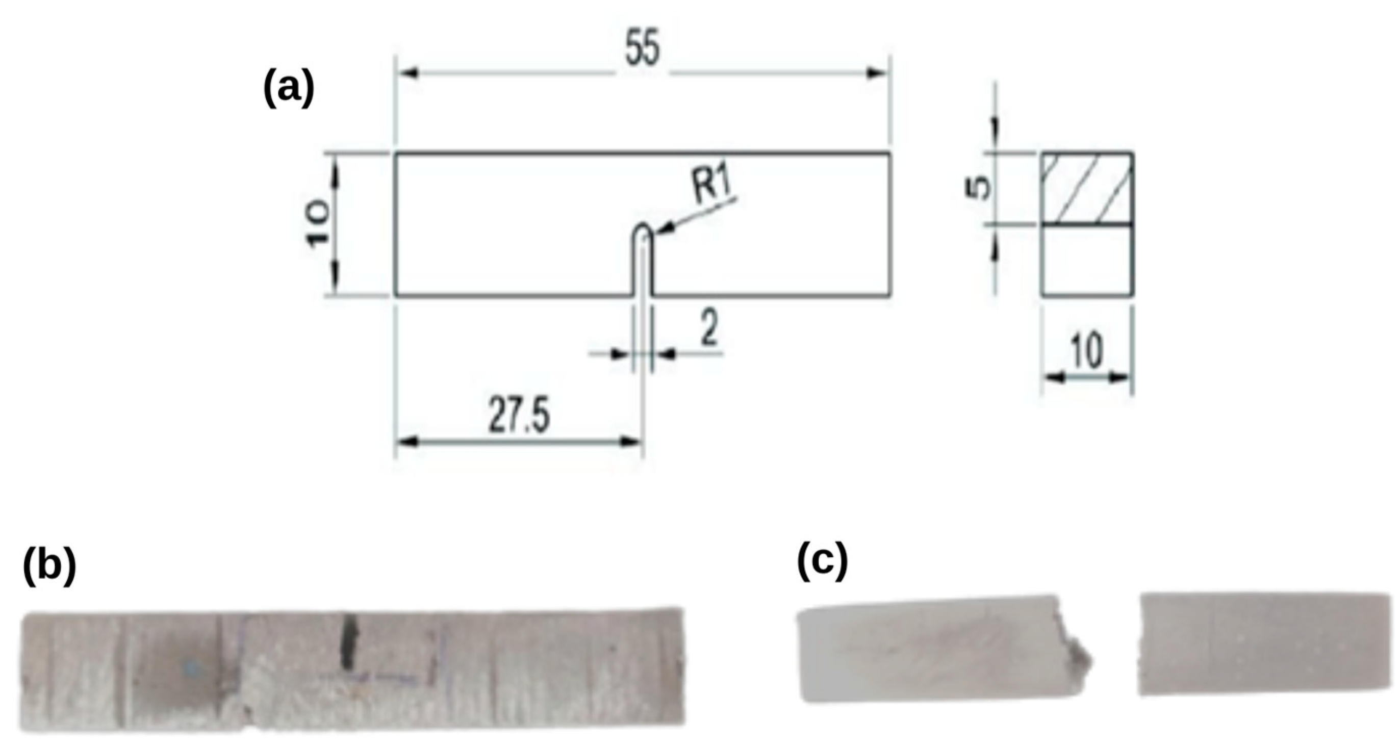
Final TIG-welded workpieces were machined using electrical-discharge machining to obtain the desired tensile and impact test specimens. An electronic tensometer was used to study the behavior of the prepared sample for the tensile test. While strictly following ASTM E8M standards for 120 × 20 mm tensile specimens, 4 tensile test specimens were prepared, with 3 being welded at 150, 170 and 200 A, and the last specimen being non-welded. These tensile specimens were later tested to find the ultimate tensile strength and percentage elongation.
Figure 1a shows ASTM E8M dimensioning, with (b) and (c) showing the condition of the specimen before and after.
The electronic tensometer was used to measure the tensile strength of the prepared standard tensile specimens. It provided the peak load and break load of every specimen and the peak and break displacement.
Figure 2a shows the Charpy specimen dimensions according to the IS 1499-1959 standard. After making a “U” notch on the prepared impact specimen, the Charpy impact test was carried out using the pendulum impact tester to determine the impact strength of the specimens.
Impact strength is a material characteristic, and metals with a high impact strength can absorb high shock and impact energies before fracture. A notched pendulum was used to sever the test specimen in this test. The energy absorbed by the specimen (in joules) was the impact strength. A total of 4 impact specimens were machined, which were TIG-welded at 150, 170 and 200 A and non-welded.
Figure 2b,c shows a Charpy specimen sample before and after fracture. The fractures were later analyzed using scanning electron microscopy (SEM) and energy-dispersive spectroscopy (EDS). The electronic tensometer used in this work was obtained from Kudale Instruments, model PC-2000, a horizontal tensile testing machine with a capacity of 20 KN. The impact-testing machine used was obtained from Fuel Instruments & Engineers, model IT-30, with a maximum load capacity of 300 J. SEM-EDS equipment was obtained from Zeiss; model EVO 15 was used for SEM-EDS analysis. EDS can generate digital mapping images, which are compositional maps of a sample. EDS maps are generally recorded with a silicon drift detector and may indicate the location of each element analyzed. The brightness of the maps is proportional to the intensity of the pixels in the sample. However, the present work did not employ the mapping techniques, and only simple analyses were carried out.
3. Results and Discussion
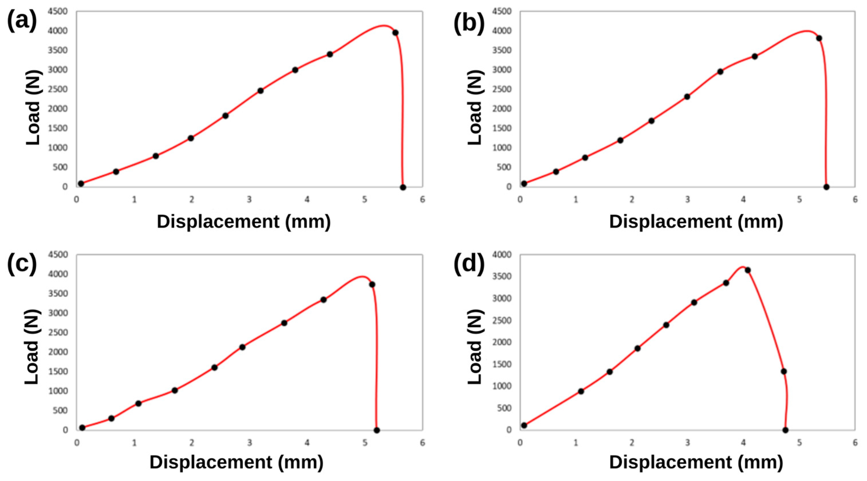
Figure 3 shows the peak load and elongation plot for each specimen welded with different welding parameters. It was observed that the non-welded tensile specimen had a lower peak load and percentage elongation as compared to the welded specimens. As the welding current increased, it was observed that the material was subjected to a higher temperature and a faster rate of cooling, which reduced its elastic nature, making the weld region brittle. The differences between the weld samples may have been caused by the inclusion of a weld filler material with substantial silicon, carbon, and magnesium contents, due to the strong interface that distributed and transmitted the load from the matrix to the reinforcement and exhibited a higher elastic modulus and strength in the welded specimens, since the welding current regulated the mechanical properties [
19].
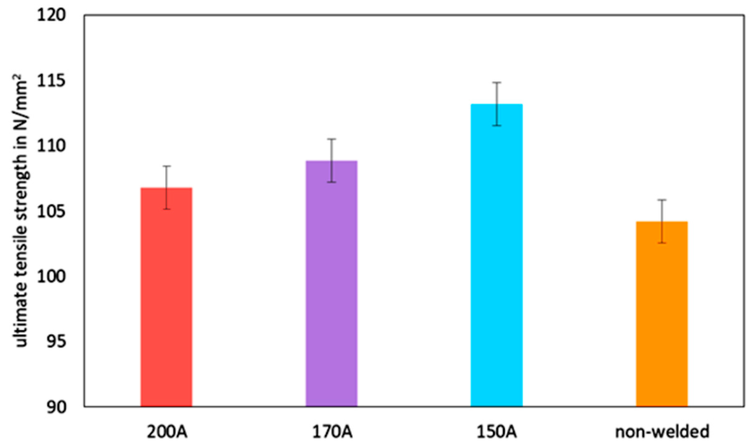
Figure 4 represents the UTS, showing an increase in tensile strength in the 150 A welded specimen that gradually decreased as the welding current increased.
This was because the current and voltage increased the arc length, which increased the heat generated at the weld zone; subsequently, this increase in heat caused the arc cone to spread at its base, resulting in a wider weld and deeper penetration [
20], which led to solidification cracking. The decrease in the UTS value may have been due to the brittle nature of the higher-current weld zone and the embrittlement of the reinforcement [
21]. An 8.27% improvement in the UTS was observed for specimens welded at 150 A. A 4.39% increase in the UTS was observed for 170 A, and a 2.4% increase in the UTS for specimens welded at 200 A. Increasing the weld current has a direct influence on the mechanical properties of reinforcement particles [
22]. The error bars for different UTS values (150, 170, 200 A, and non-welded) were plotted. The error bars represented a standard deviation and confidence interval of (108.25 ± 1.625), which was ±1.52% from the mean. This showed that there was no overlap between the data of the non-welded specimen and those of the TIG-welded specimens, and that the data obtained for the two specimens were unique.
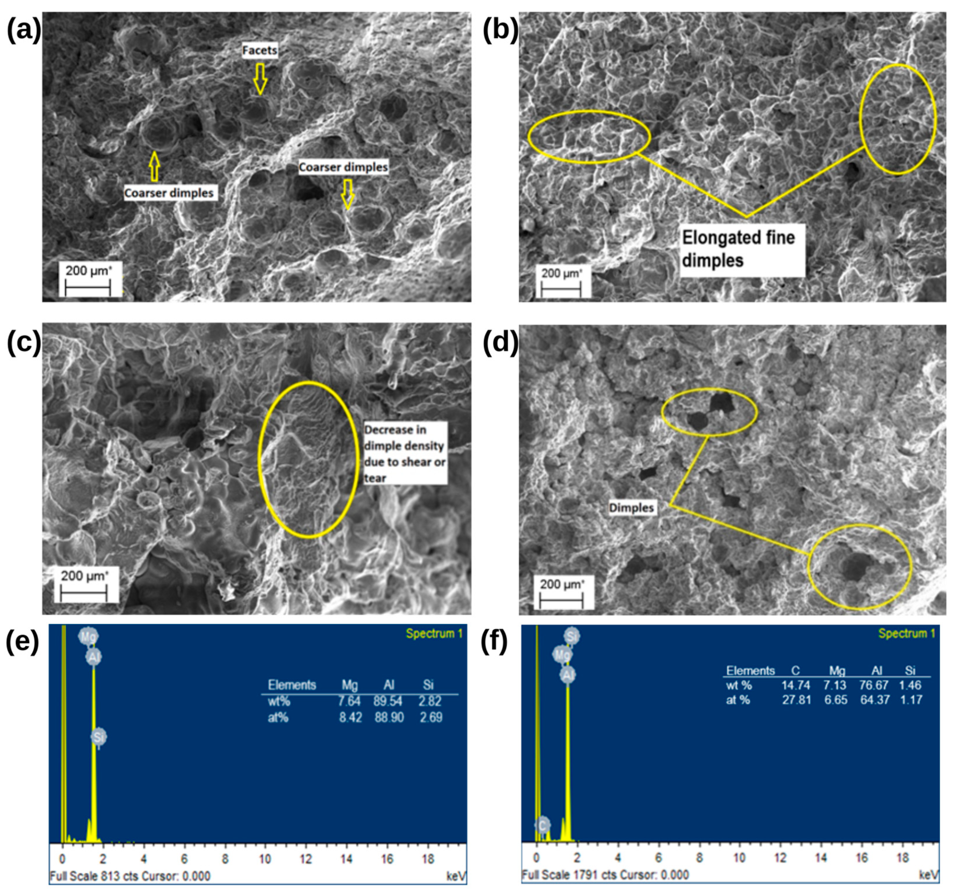
SEM tests followed the tensile testing to assess the fracture behaviors and interface bonding between the matrix and reinforcing components. Specimens were obtained from entire sections of the fractured surfaces and placed into the SEM apparatus to explore the microstructures of these surfaces. SEM pictures were acquired at 200 µm from the specimens’ shattered surfaces. Compared to the non-welded specimens from
Figure 5d, the welded specimens shown in 5a–c had greater dimple development on the shattered surface.
Figure 5a shows the presence of a dominant mixture of coarse and finer dimples, which reflected high tensile strength. As a result, it was observed that the specimen welded at 150 A had better ductility. The appearance of such a fractured surface is referred to as a dimple rupture. In
Figure 5b, the coarse dendritic structures and finer elongated dimples represent a ductile failure mode, but equiaxial dimples were greatly reduced.
Crack propagation was evident in the discontinuous river patterns along the ridges. Tiny gaps frequently start, develop, and combine during plastic deformation to generate ductile fractures. Normally, the interfaces between inclusions and second-phase particles are where voids first form. It is believed that the major mechanism of void nucleation is the dissociation of these points of contact. After the voids form, continuing plastic deformation increases their size and changes their shape, a process known as void growth [
23]. It was noted that the specimens welded at 170 A and 200 A had lower tensile strength and elasticity but higher hardness. This may have been due to the brittle nature of the weld due to shearing and a lack of a dimple array. In
Figure 5d, the non-welded sample shows signs of micro-voids. These micro-voids result in stable and unstable crack propagation [
24].
The EDS showed the composition of welded and non-welded specimens.
Figure 5f shows the EDS elemental composition of the weld zone and confirms the presence of SiC in the welded specimen, and
Figure 5e shows the elemental composition of the Al6061 alloy.
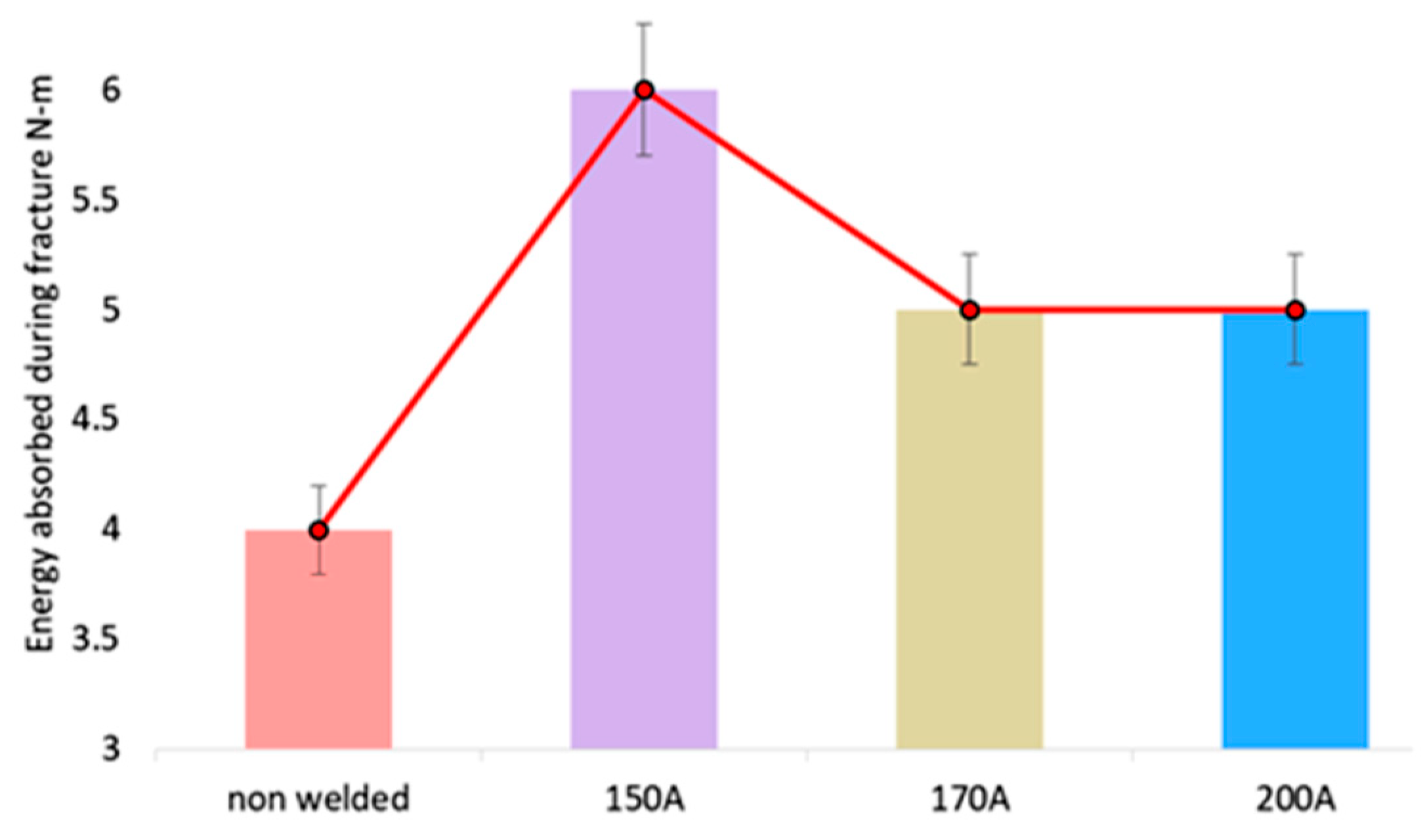
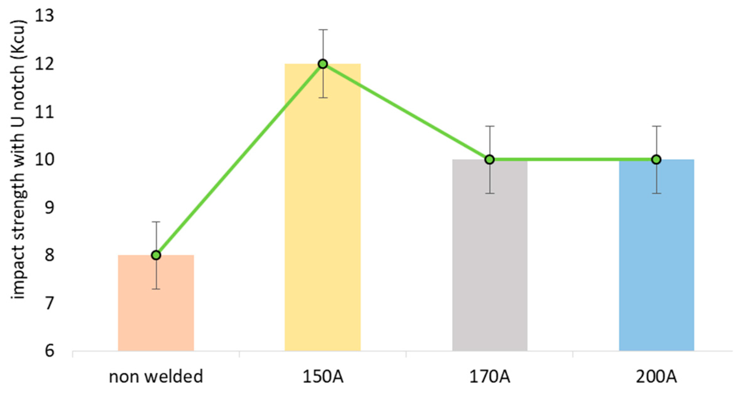
A conventional test piece with a “U” notch held and supported at both ends was fractured by a single strike from a swinging hammer with an impacting force of 300N-m. The impact test was performed for non-welded specimens and 150, 170 and 200 A TIG-welded specimens. It was established that the welded specimen had significantly higher impact strength than the non-welded specimen. A 40% increase in energy absorption was determined for the specimen welded at a current of 150 A. A 22.2% increase in impact strength was observed for the 170 A and 200 A specimens. The error bar plotted for the 150, 170, 200 A, and non-welded specimens represented a standard deviation and confidence level of 7.07% from the mean, as shown in
Figure 6 and
Figure 7.
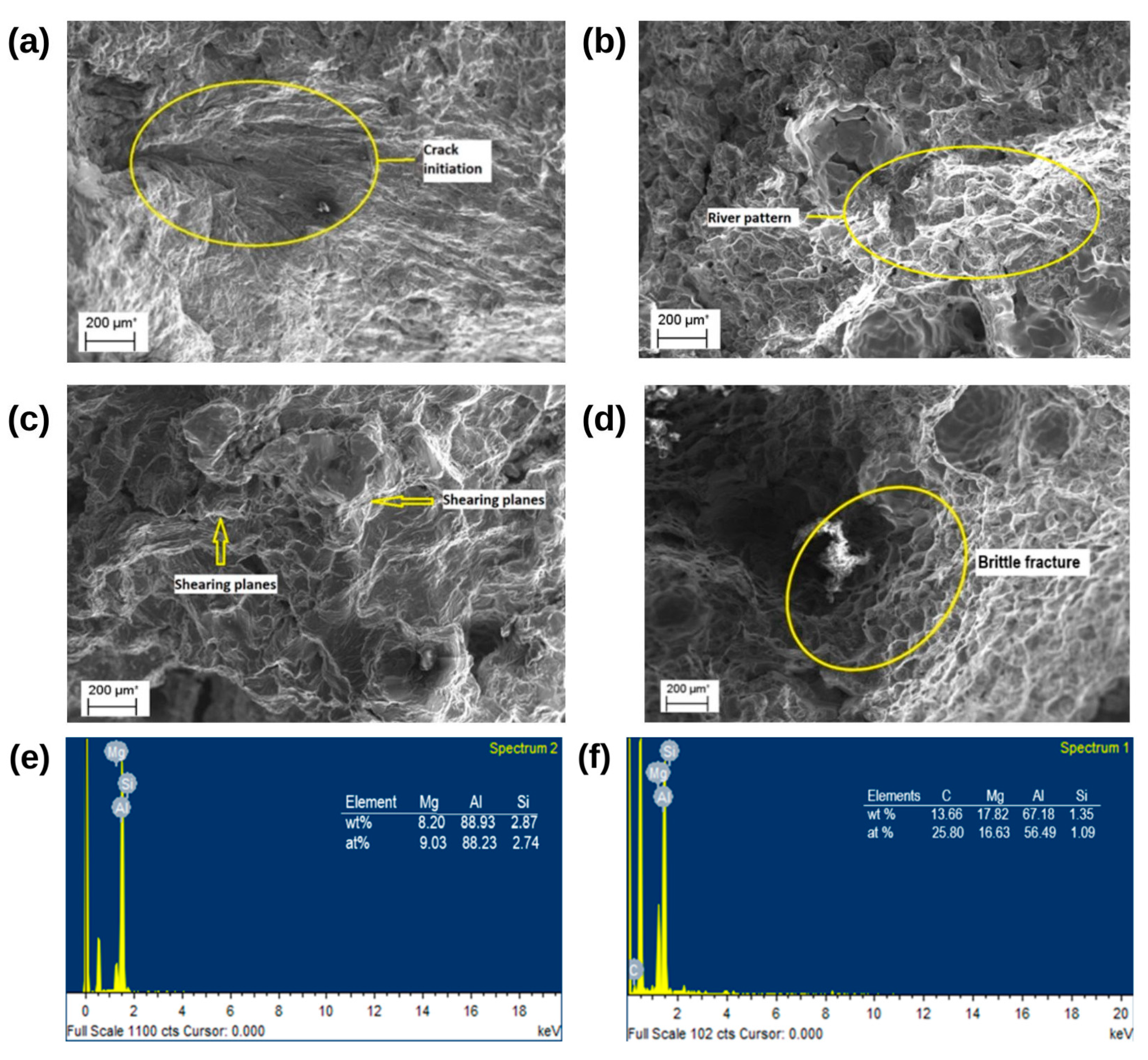
Intrusions start most micro-cracks. As a result, slip bands are crucial at the beginning of fatigue cracks [
25]. In
Figure 8a, the area of crack initiation in the material is located on the internal surface of the specimen, with the presence of surface ripples, known as “striations”. Ductile shallow striations can be observed on the fracture surface. Fatigue, SCG, and quick fracture are factors that can cause striations or lines to form on fracture surfaces. These are unique curved lines on a fracture surface and may be connected to crack progression through the material. After initiating at the grain boundaries, the cracks traveled along a slip band path. The authors of [
26] revealed that interactions between persistent slip bands and grain boundaries depended on intergranular fatigue cracking. Crack initiation is caused by porosity, oxide inclusions, and ductile deformation [
13]. Overall, the SEM images revealed striations on the welded specimen, with uniformly dispersed finer dimples being dominant compared to the non-welded specimens, which were ruptured and dominated by shallow dimples. Continuous river patterns were also observed on the non-welded specimen (
Figure 8b), which indicated brittleness. One can observe in
Figure 8b that the pattern originated along the diagonal path and propagated to the bottom of the image. The pattern initially consisted of several small steps that combined to form a number of major steps.
Figure 8c shows shearing planes, a ductile failure.
The localized strain concentration due to the sudden impact might have caused the formation of the shearing planes. Quasi-cleavage fracture was also noticed. As the ripping ridges grew, a quasi-cleavage stage characterized by brittle fracture developed. The alloy’s rise in the quasi-crystal phase caused the microstructure to be inhomogeneous, which in turn caused a stress concentration and cracking source initiation, leading to the specimen’s brittle fracture. The characteristics of both cleavage and plastic deformation led to the formation of quasi-cleavage fractures.
Figure 8d shows the brittle fracture.
This might have been caused by an increase in the solidification distance, which caused the melt to solidify more slowly and resulted in coarser, longer particles. However, this also has certain drawbacks, because there are more opportunities for large, elongated particles to crack [
27]. A transgranular fracture is a brittle fracture that propagates through the microstructure without abiding by the grain boundaries. When a transgranular brittle fracture surface is seen at a high magnification, microscopic river lines resembling the macroscopic river lines that may be seen on a brittle fracture point towards the direction of the fracture initiation point. The EDS assay revealed the composition of the welded and non-welded specimens.
Figure 8f shows the EDS elemental composition of the weld zone and confirms the presence of SiC in the welded impact specimen, and
Figure 8e shows the elemental composition of the Al6061 alloy.
4. Conclusions
In the present work, stir casting was performed using Al6061 containing 6 wt. % silicon carbide particles to prepare tensile and impact test specimens, which were TIG-welded at 150, 170, and 200 amps using an AC source and later subjected to testing, providing the following results. With an increase in the TIG welding current, the Al-SiC MMC showed a decrease in peak load and percentage elongation. The specimen welded with a current of 150 A showed an 8.27% increase in UTS.
According to the fracture analysis, coarser dimples were more prominent, which resulted in better ductility and greater strength. The specimens welded at currents of 170 A and 200 A showed a mixed (ductile and brittle) failure mode. Their UTS decreased by 4.39% and 2.4%, respectively. From this, it was understood that a higher welding current directly affected the mechanical and microstructural properties. Overall, the specimen welded at 150 A showed the most promising results.
It was established that the specimen welded at a current of 150 A had a significantly higher impact strength than those welded at 170 and 200 A. Compared to the non-welded impact specimens, the impact strength was increased by 40% for the 150 A specimen. Ductile striations and finer dimple formations were more dominant. The impact specimens welded at 170 and 200 A showed lower impact strength at 22.2%. The SEM images revealed shallow dimples, continuous river patterns, and shearing planes, resulting in a mixed mode of quasi-cleavage fracture.


 ,
, 
