Article

Micro-Scale Model of rCF/PA6 Spun Yarn Composite

Institute of Textile Machinery and High Performance Material Technology, Technische Universität Dresden, 01069 Dresden, Germany
*
Author to whom correspondence should be addressed.
J. Compos. Sci. 2023, 7(2), 66; https://doi.org/10.3390/jcs7020066
Submission received: 29 November 2022 / Revised: 6 January 2023 / Accepted: 3 February 2023 / Published: 6 February 2023
(This article belongs to the Special Issue Characterization and Modelling of Composites, Volume III)

Abstract

:
Recycling carbon fibers (rCF) for reuse is one approach to improve the sustainability of CFRP. However, until now, recycled carbon fiber plastics (rCFRP) had limited composite properties due to the microgeometry of the fibers, which made it difficult to use in load-bearing components. The production of hybrid yarns from rCF and PA6 fibers allows the fibers to be aligned. The geometric properties of the yarn and the individual fibers influence the mechanical properties of the composite. An approach for the modeling and simulation of hybrid yarns consisting of recycled carbon fibers and thermoplastic fibers is presented. The yarn unit cell geometry is modeled in the form of a stochastic fiber network. The fiber trajectory is modeled in form of helical curves using the idealized yarn model of Hearle et al. The variability in the fiber geometry (e.g., length) is included in form of statistical distributions. An additional compaction step ensures a realistic composite geometry. The created model is validated geometrically and by comparison with tensile tests of manufactured composites. With the validated model, multiple parameter studies investigating the influence of fiber and yarn geometry are carried out.

1. Introduction

Carbon fiber reinforced polymer composites (CFRP) are nowadays used in many weight-sensitive industries, e.g., aerospace and automotive. From a sustainable point of view, it is necessary to recycle end-of-life components or cutting waste and to reuse them with high quality for load-bearing components. Various methods have been developed for this purpose, but for the most part only materials with low mechanical properties can be produced for non-load-bearing components [1]. However, there are also approaches to produce high-performance materials from recycled carbon fibers (rCF).
Non-structural usage of rCF as nonwovens [2,3,4] or fiber-reinforced thermoplastic compounds produced by an injection molding process [5,6,7] were investigated. However, these materials have poor fiber orientation and low fiber volume content. The manufacturing of tape structures from rCF was investigated in order to provide pre-consolidated structures for thermoplastic composites [8,9,10]. Khurshid et al. [10] reached a tensile strength of UD composite of up to 1370 MPa with a rCF/PA tape. Main factors influencing tensile properties, in addition to CF length and fiber volume content, are the fineness of CF and PA and the process parameters for thermal fixation and consolidation of tapes.
Advantageous properties of rCF can be achieved with yarn spinning technologies, such as flyer spinning, friction spinning and wrap spinning [11,12]. In the carding process, the fibers are first aligned. The card web is then transformed into slivers, which are then spun to yarns. Blending with thermoplastic fibers such as PA6, PP and polyester is used to obtain hybrid yarns, since processing of pure CF is challenging. The main challenge is the preservation of high fiber length. Fiber damage occurs in the process steps, mainly during carding and drawing [13]. Hengstermann et al. have developed hybrid yarns from rCF and a thermoplastic fiber (PA6) [11,14]. They used a flyer machine to produce yarns. Tensile tests of unidirectional (UD) composites showed excellent properties with tensile strength up to 900 MPa at 50% fiber volume content [15]. Yarn twist and CF length have an influence on tensile properties. Hasan et al. [16] used friction spinning to produce core-sheath hybrid yarns from staple CF and PA6. They received tensile strength of more than 1000 MPa at fiber volume content of around 42%, which is close to the reference made of continuous CF. Goergen et al. [17] used rCF/PA6 staple fiber yarns to produce organic sheets, i.e., impregnated fiber-reinforced thermoplastic sheets. They applied core-spun yarns as the basis. Miyake and Imaeda [18] have modified the yarn manufacturing process to align discontinuous CF. The main sources of fiber damage are the carding and drawing process steps, which necessitates gentle processing of brittle CF.
To tackle the challenge of modeling of the strength of fiber-reinforced composites based on the properties of its components, different approaches have been taken. They are distinguishable into analytical, semi-analytical-numerical and numerical approaches and differ in the required input information as well as the grade of insight gained from the results.
Cox introduced the analytical shear-lag model to describe the mechanical behavior of composites containing short fibers [19] which has been universally applied and extended [20,21,22,23]. Shah [24] extended the Tsai-Hill composite laminate model [25] to predict the strength of composites made from unidirectional plant fiber yarns, while considering yarn properties like fiber length in form of a constant factor.
An alternative approach to predict the composite strength is the application of global load sharing (GLS) [26,27,28,29]. For the GLS approach, fibers with heterogeneous material properties are assumed, resulting in an inhomogeneous failure history. Thereby, the ability of adjacent fibers to take up the load of the failed fiber is decisive for the failure behavior. The GLS usually utilizes the Monte-Carlo approach to simulate a multitude of runs to predict the composite properties, and, so far, has only been used to model aligned composites. Discontinuous composites have been modeled only with fiber lengths up to 3 mm [29,30].
For the implementation of composite material models with more complex micromechanical geometries, the finite element method (FEM) is a suitable solution. By using unit cell models, which are created under the assumption that the composite is composed of an array of cells of equal geometry, the numerical cost can be limited. The unit cell approach has been used for short fiber reinforced composites with fiber lengths lower than 10 mm [31,32,33], as well as endless fiber reinforced composites [34,35]. Harper et al. [36] created discontinuous carbon fiber reinforced composites using fibers with a length up to 10 mm in a two dimensional FEM model. Fliegener et al. [37] modeled thermoplastic composites with glass fiber reinforcements including a length distribution of up to 50 mm. The final geometry was determined by a virtual compaction test of stacked up linear fibers with a defined fiber orientation distribution.
A promising approach for the modeling of composites with inclusions is the domain superposition technique (DST). It enables the coupling of inclusion (fiber) elements to host (matrix) elements with multi-point constraints, eliminating the need for a matching mesh in the interfaces of both partners. The approach has already been applied to simulate the properties of composites constraining beams [36,38,39,40,41,42], shells [43], and solids in a solid host mesh [44,45]. So far, the investigation of composite failure with DST has mainly been used in meso-mechanical models.
In summary, no approach for the modeling of long fiber reinforced composites with fiber lengths greater than 50 mm with complex fiber paths, such as in yarns, has been presented in the literature. Therefore, a method to generate near-micro-scale models for composites made of discontinuous rCF and PA6 matrix based on spun yarns is described in this paper.

2. Materials and Methods

2.1. Materials

As a basis for the composite manufacturing, multiple ring-spun hybrid yarns made from rCF and Polyamide 6 fibers were produced. The recycled carbon fibers were obtained from bobbin ends and cut into defined lengths of 100 and 80 mm. For the Polyamide fibers, staple fibers with a length of 80 mm (Barnet Europe, W. Barnet GmbH & Co. KG, Aachen, Germany) were chosen. The mechanical properties of the fibers were determined by filament tensile tests in accordance with DIN EN ISO 5079. All fiber tensile tests were performed using the FAVIMAT fiber tensile tester (Textechno Herbert Stein GmbH & Co. KG, Mönchengladbach, Germany). An overview of the fiber properties is provided in Table 1.
The fibers were processed in multiple steps similar to the one utilized in conventional yarn production consisting of a carding, drawing and spinning step. For each process step, special attention was paid to a gentle processing in order to reduce damaging and shortening of the brittle carbon fibers. More detailed descriptions of the production process and the chosen processing parameters are given elsewhere [46,47]. To investigate the influence between yarn twist and composite properties, the processing parameters during the spinning step were varied, creating yarns with a constant linear density of 1000 tex and a varying twist between 20 and 75 T/m.
In order to determine the properties of composites made from hybrid yarns, unidirectional (UD) plates (length × width × thickness = 250 × 25 × 2 mm3) were produced by wrapping on a wrapping frame (IWT Industrielle Wickeltechnik GmbH, Erlangen, Germany) and subsequent vacuum-assisted consolidation on a thermal press (P 300 PV, COLLIN Lab & Pilot Solutions GmbH, Maitenbeth, Germany). With these UD plates, tensile tests based on DIN EN ISO 527-5 were carried out. The fiber volume content was determined according to ASTM D 2734 by burning off the matrix from the composite specimens. An overview of the composite properties depending on yarn twist is given in Table 2.

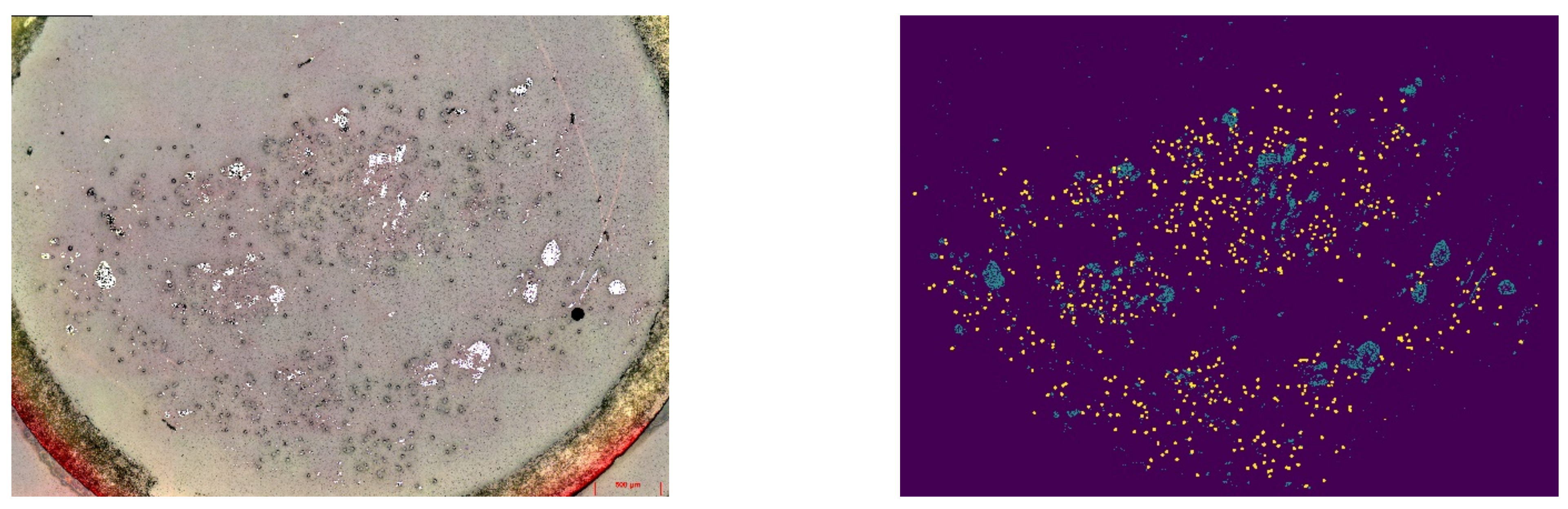
2.2. Filament Geometry

For the analysis of the filament geometry in the yarns and the composites, specimens were created by embedding the yarns and composites in an epoxy resin matrix and cured at ambient temperature. After polishing and cleaning of the specimens, cross-sectional images were taken on an optical microscope Axio Imager M1m (Carl Zeiss, Germany).
By using the software ImageJ, geometrical data such as fiber cross-section or yarn diameter are determined (Figure 1). The fiber length was determined using the fibrogram method based on the approach of Hengstermann et al. [48].

2.3. Micromechanical Yarn Modelling

To achieve a unit cell (UC) that closely replicates the composite geometry, a multi-step approach was chosen. Instead of generating the composite model directly, a yarn model was first generated, which was virtually compacted in the second step. In this way, the process parameters of the yarn production (e.g., fiber length, twist) could be easily integrated into the model. In the next sections, an overview of the main steps during the yarn creation, compaction and virtual composite simulation are provided.

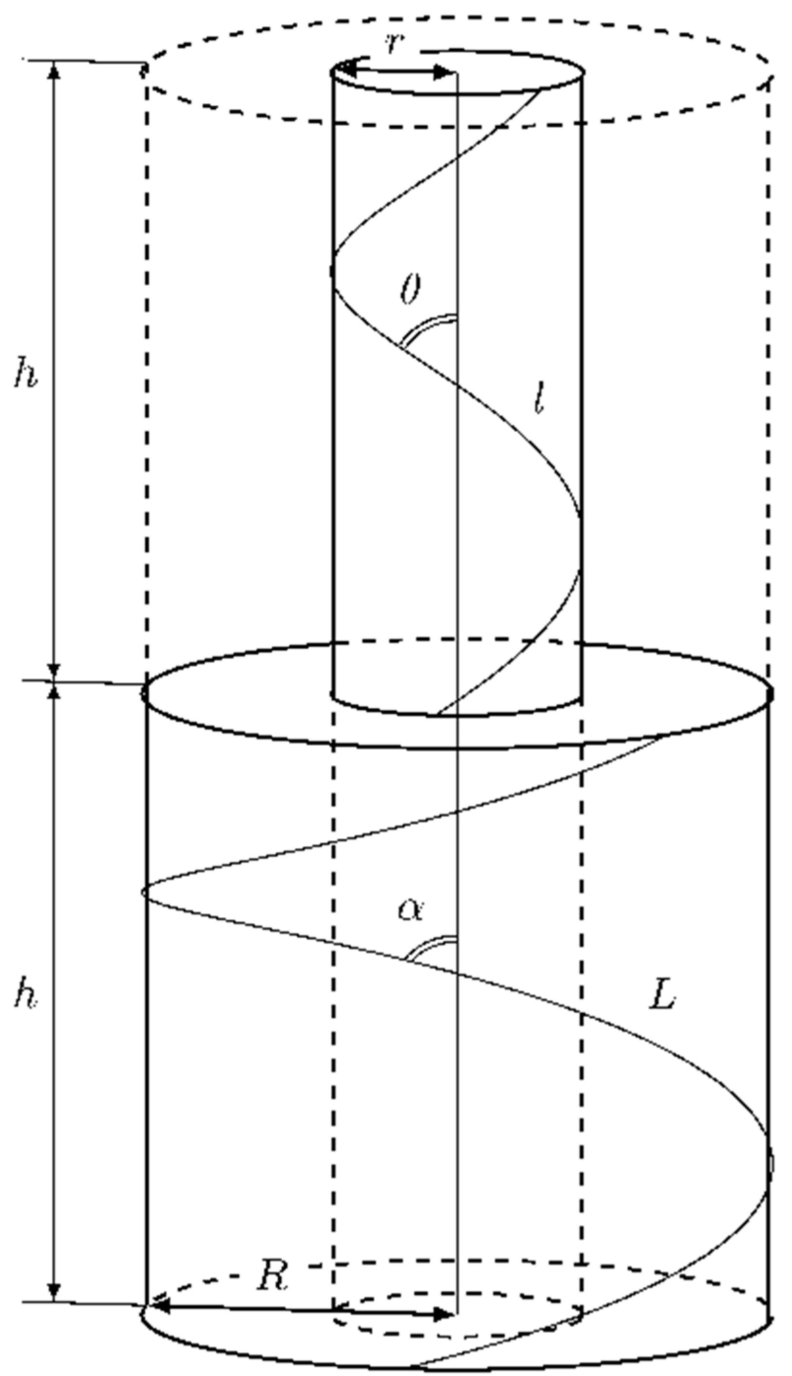
2.3.1. Geometrical Assumptions

In order to generate a realistic approximation of the yarn geometry, an algorithm to model the unit cell geometry was developed. An idealized approach based on the assumptions of Hearle et al. [49] was chosen for the geometric modeling of the hybrid yarns. The yarn cross section was assumed to be circular with a constant radius along the yarn axis. One yarn comprised a multitude of filaments of finite length. Each fiber was assumed to lie on a helical path. Fiber migration was neglected, i.e., distance between fiber and yarn axis was constant. In Figure 2, an idealization of the yarn geometry with two fibers of a varying distance between fiber and yarn axis ( r and R ) is provided. At a constant pitch h , the fiber angled to the yarn axis ( θ and α ) and, therefore, the fiber lengths ( l and L ) were only dependent on the distance between fiber and yarn axis.
The fiber trajectory was therefore described with r for the helix radius, h for the pitch and c for the offset by Equation (1). The pitch was the reciprocal of the twist T .
x t = r cos 2 π t r s i n 2 π t h t + c

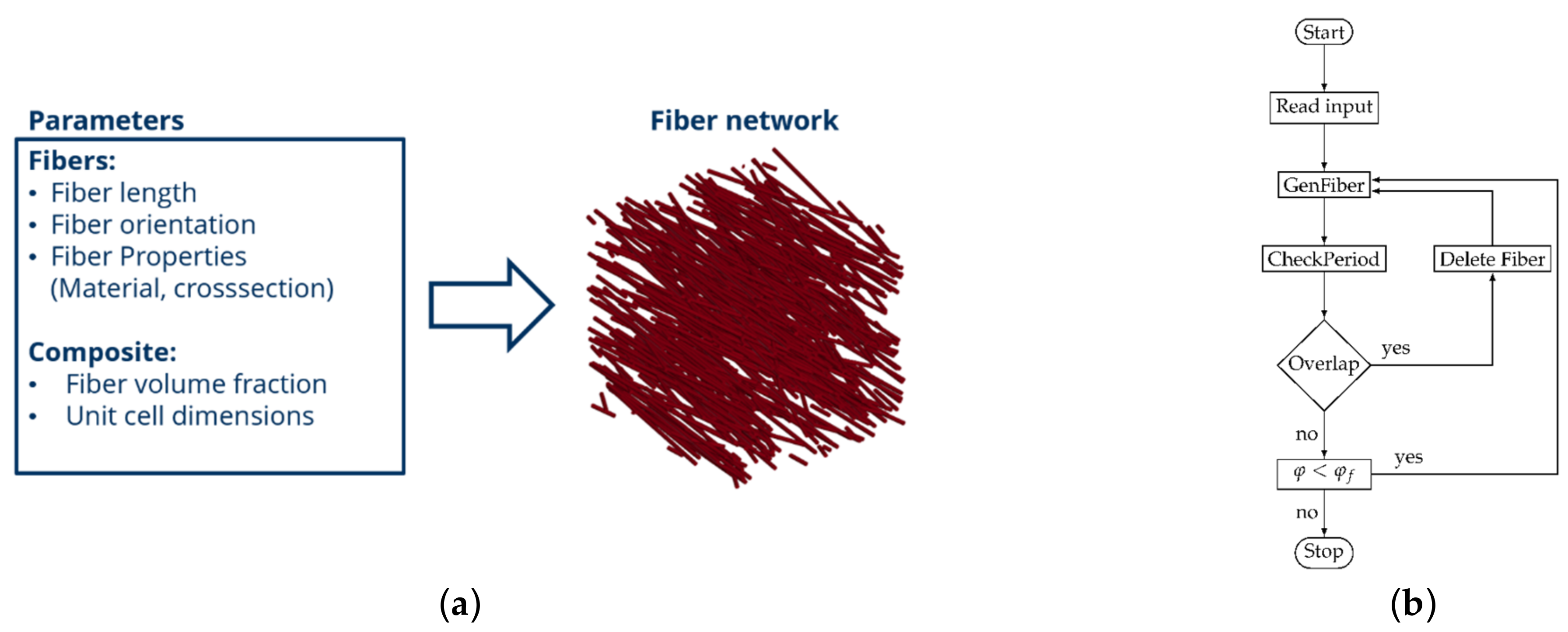
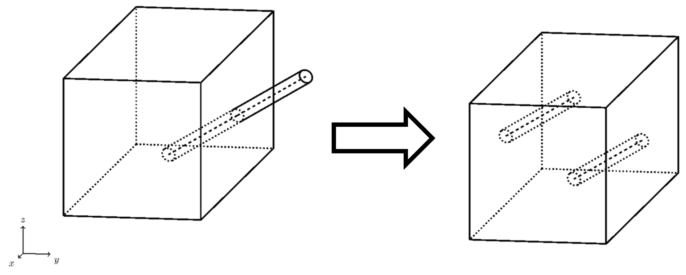
2.3.2. Geometric Modelling Approach

To determine the composite properties based on filament geometry, three-dimensional representative unit cell (RVE) models were created. Because of the multitude of parameters needed for the creation, a custom algorithm was developed to generate the yarn geometry. The main algorithm was based on the random sequential adsorption method approach [50]. Figure 3 provides an overview of the main processing steps for the unit cell generation.
After reading the input containing information on the unit cell volume, fiber geometry and packing fraction, the RVE geometry was created by iteratively adding fiber elements to the fiber network. The fiber elements were thereby discretized by one-dimensional elements. To create a fiber, first an initial random point in the RVE volume was chosen. The fiber path was modeled based on the previously described idealization as a helix curve, with the twist and fiber length provided by the user input. From the initial point, the radius and offset were derived.
After the fiber geometry was created and a check for periodicity was carried out. If the fiber intersected the boundaries of the UC volume, it was split into two. The out-of-bounds fiber was then translated to opposite boundary (Figure 4).
After the periodic testing, the fibers were tested for an overlap with the existing fiber network. The fiber trajectories were discretized by a chain of points. The distance between each created point was chosen to be equal of the fiber radius r f (see Figure 5).
The intersection between the fibers was tested with Equation (2). The parameter P n described all created points of the new fiber, P o described the existing points. The new fiber radii were provided by r f , the existing radii by r o . An additional parameter a r was included to assure a minimal distance between each fiber.
d f f = p n p o r f + r o + a r > 0 p n P n ; p o P O
If an intersection was found, the new fiber was discarded and a new fiber was created. If no intersections could be found, the new fiber was appended to the existing fiber network. By comparing the current fiber packing fraction φ to an initially defined packing fraction φ f , the described loop was provided with an exit condition. After reaching the final packing fraction, the fiber geometry, as well as information on the fiber cross section and material properties was outputted to a file for further use in simulations.
The described approach was implemented with python. By using the open-source library SciPy [51], the geometric parameters were provided in the form of statistical distributions, which enables the modeling of the stochastic nature of yarn geometry (see Figure 6).

2.3.3. Finite Element Modeling

Before carrying out simulations to determine the composite properties, the fiber network was subjected to compaction in an intermediate simulative step. Virtual compaction of the fiber geometry provided a realistic fiber geometry with the final fiber volume fraction in the composite material. Because of their high aspect ratio, the filaments in the modeled yarn geometry were approximated by one-dimensional beam element chains following the approach described in Döbrich et al. [39]. Based on Döbrich’s conclusions, to model the composite behavior, a near-microscale approach was sufficient. Therefore, to limit the numerical cost of the model, the fiber cross-sections was chosen to be bigger than the real measured one. For the upper limit, the accurate representation of the local randomness of the unit cells was chosen. An overview of the selected model parameters is shown in Table 3. The material behavior of the carbon fibers was modeled by a linear elastic material model with a stress-based failure condition. The Young’s modulus was selected based on Table 1. To model the matrix component, an eight-noded hexahedral mesh was chosen. Because of its nonlinear stress-strain-behavior, an elasto-plastic material model was used. The tensile curves of the single fiber tensile tests and the simulation result are compared in Figure 7.
The compaction process was modeled using an explicit simulation. The yarn geometry (yarn axis oriented parallel to the z-axis) was confined inside of six planar rigid walls located at the yarn dimensions. While fixing the walls at the y- and z-border, a velocity boundary condition was applied on both planes at the x-border towards each other. The compression was carried out until the final fiber volume fraction in the composite was achieved. To ensure the periodicity of the fiber geometry, periodic boundary conditions in × and y-direction were applied on the boundary nodes. In the z-direction, the fibers were fixed to the boundary. The fiber-fiber interactions were modeled with a segment-based penalty contact formulation.
The deformed fiber geometry was used for further composite simulations. To create the composite model, the previously described DST was applied. In the DST approach, the velocities and accelerations of beam and solid elements were constrained in each direction under the assumption of an ideal fiber-matrix interface. Figure 8 shows the approach.
For the comparison of the model performance with experimental composite properties, virtual mechanical tests in the yarn direction were carried out. At the model boundaries, periodic boundary conditions were applied. The model results were homogenized for comparison to experimental data under the assumption of small strains by volume averaging of the model stresses σ i j over the model volume V following Equation (3).
σ i j = 1 ν ν   σ i j d V    

3. Results and Discussion

3.1. Model Validation

Using the method described above, different unit cells of the yarn geometry were generated. The geometric yarn model was validated for a yarn with 30 twists/meter by comparing model images with microscopic images (see Figure 9).
Although the constituting yarn parameters (diameter, packing density, twist, surface angle) could be successfully represented in the model, deviations in the geometrical appearance remained. The influence of yarn hairiness, mainly caused by protruding fiber ends, had a large influence on the yarn appearance. The influence on the composite’s mechanical behavior was assumed to be limited and therefore neglected for the composite modeling. Therefore, a good agreement between modeled and determined yarn geometry was assumed.
By performing the compaction simulation, the yarn geometry was transferred into a realistic composite geometry. During compaction, the fiber geometries were aligned in the axial direction, which had a positive effect on the mechanical behavior in the UD composite. Figure 10 shows the result of the compaction simulation using a yarn with 30 t/m as an example. The shift of the nodes in the axial direction indicated a rearrangement of the fibers during compaction. The compacted model geometry was further geometrically validated by comparison with micrographs (Figure 11). A good agreement with the micrograph geometry was found.
The composite modeling and simulation were as described above. During the implicit simulation, premature terminations occurred. The reason for the premature termination was the rapid failure of several fiber clusters, which was also the cause of the failure of the composite in reality. Therefore, the premature termination of the simulation was chosen for the determination of the maximum strength.
The tensile behavior of the model showed a linear failure behavior similar to the test (Figure 12). During the composite simulation, stress peaks occurred near the fiber ends (Figure 13).

3.2. Parameter Study on Yarn Geometry

With the help of the validated model, parameter studies using five simulations per parameter value were carried out to investigate the influence of different geometrical parameters of the yarn on the composite behavior. For better clarity, the simulation results were normalized in the following figures.
In Figure 14, the yarn twist was varied between 5 and 80 t/m. A detrimental influence of yarn twist on the composite strength and modulus is shown. Yarn twist below 20 T/m resulted in a reduction in the composite properties. This was due to the compaction step. Because of the overall better fiber orientation, the influence of local variabilities on the composite properties increased, leading to a wider variance in the composite strength.
Further investigations were carried out on the influence of yarn packing (Figure 15). The variation of the packing density influenced the degree of compaction necessary to achieve the fiber volume content in the composite, and thereby the grade of disorientation of the fibers in the composite. This is of particular interest at low yarn twist, where the lack of self-compacting mechanisms of the yarn led to very low packing densities in the yarn. An improvement of the yarn packing fraction, even at low twist could have further improved the composite properties.
Figure 16 examines the influence of fiber length distribution on composite behavior. A variation of the shape parameter of the Weibull function for fiber length distribution influenced the standard deviation of this fiber length distribution (Figure 16 left), thus allowing fibers with lower lengths to occur. The scale parameter was changed accordingly, so that the expected value stayed constant, in accordance with the measured fiber length. The results showed no discernible influence of Weibull shape parameter on the composite properties.
So far, the model has not considered short fibers. However, it was shown to significantly affect composite properties [10]. In Figure 17, the influence of short fiber content (SFC) on the composite properties is investigated. Because the applied method of length determination was limited for short fibers (fiber length <12.7 mm), the applied distribution was skewed for longer fiber lengths. In the model, SFC of varying volume content were included, while ensuring a constant fiber volume content in the composite. The simulation results of the composite showed a decrease in strength with higher SFC, while the influence on the composite modulus was limited.

4. Conclusions

In this article, a method for modeling yarns made from recycled carbon fibers with varying fiber length and polyamide 6 was presented. The modeling approach applied the idealized assumptions of Hearle et al. for the creation of yarns consisting of a stochastically distributed fiber network. Validation was carried out on the basis of micrographs and tensile tests of the composite. Parameter studies were carried out with the validated models and the influence of different yarn parameters on the composite behavior was investigated. The developed approach thus provides a solid basis for the design of rCF hybrid yarns regarding the composite behavior.

Author Contributions

Conceptualization, T.G., A.A. and C.C.; methodology, T.G.L. and M.M.B.H.; software, T.G.L.; validation, T.G.L. and M.M.B.H.; formal analysis, T.G.L.; investigation, T.G.L. and M.M.B.H.; resources, T.G.L.; data curation, T.G.L.; writing—original draft preparation, T.G.L. and T.G.; writing—review and editing, T.G., M.M.B.H., A.A. and C.C.; visualization, T.G.L.; supervision, T.G., A.A. and C.C.; project administration, T.G., A.A. and C.C.; funding acquisition, T.G., A.A. and C.C. All authors have read and agreed to the published version of the manuscript.

Funding

Funded by the Deutsche Forschungsgemeinschaft (DFG, German Research Foundation)—407164652.

Data Availability Statement

Not applicable.

Conflicts of Interest

The authors declare no conflict of interest.

References

  1. May, D.; Goergen, C.; Friedrich, K. Multifunctionality of polymer composites based on recycled carbon fibers: A review. Adv. Ind. Eng. Polym. Res. 2021, 4, 70–81. [Google Scholar] [CrossRef]
  2. Wölling, J.; Schmieg, M.; Manis, F.; Drechsler, K. Nonwovens from recycled carbon fibres—Comparison of processing technologies. Procedia CIRP 2017, 66, 271–276. [Google Scholar] [CrossRef]
  3. Stegschuster, G.; Schlichter, S. Perspectives of web based composites from RCF material. IOP Conf. Ser. Mater. Sci. Eng. 2018, 406, 012022. [Google Scholar] [CrossRef]
  4. Wei, H.; Nagatsuka, W.; Lee, H.; Ohsawa, I.; Sumimoto, K.; Wan, Y.; Takahashi, J. Mechanical properties of carbon fiber paper reinforced thermoplastics using mixed discontinuous recycled carbon fibers. Adv. Compos. Mater. 2018, 27, 19–34. [Google Scholar] [CrossRef]
  5. Han, H.; Wang, X.; Wu, D. Mechanical properties, morphology and crystallization kinetic studies of bio-based thermoplastic composites of poly(butylene succinate) with recycled carbon fiber. J. Chem. Technol. Biotechnol. 2013, 88, 1200–1211. [Google Scholar] [CrossRef]
  6. Yan, G.; Wang, X.; Wu, D. Development of lightweight thermoplastic composites based on polycarbonate/acrylonitrile-butadiene-styrene copolymer alloys and recycled carbon fiber: Preparation, morphology, and properties. J. Appl. Polym. Sci. 2013, 129, 3502–3511. [Google Scholar] [CrossRef]
  7. Hirayama, D.; Saron, C.; Botelho, E.C.; Costa, M.L.; Ancelotti Junior, A.C. Polypropylene composites manufactured from recycled carbon fibers from aeronautic materials waste. Mater. Res. 2017, 20, 526–531. [Google Scholar] [CrossRef]
  8. Yu, H.; Potter, K.D.; Wisnom, M.R. A novel manufacturing method for aligned discontinuous fibre composites (High Performance-Discontinuous Fibre method). Compos. Part A Appl. Sci. Manuf. 2014, 65, 175–185. [Google Scholar] [CrossRef]
  9. Akonda, M.; Stefanova, M.; Potluri, P.; Shah, D. Mechanical properties of recycled carbon fibre/polyester thermoplastic tape composites. J. Compos. Mater. 2017, 51, 2655–2663. [Google Scholar] [CrossRef]
  10. Khurshid, M.F.; Hasan, M.M.B.; Abdkader, A.; Cherif, C. Processing of waste carbon and polyamide fibers for high performance thermoplastic composites: A novel manufacturing technology for unidirectional tapes structure. J. Ind. Text. 2022, 51, 7256S–7276S. [Google Scholar] [CrossRef]
  11. Khurshid, M.F.; Hengstermann, M.; Hasan, M.M.B.; Abdkader, A.; Cherif, C. Recent developments in the processing of waste carbon fibre for thermoplastic composites—A review. J. Compos. Mater. 2020, 54, 1925–1944. [Google Scholar] [CrossRef]
  12. Pakdel, E.; Kashi, S.; Varley, R.; Wang, X. Recent progress in recycling carbon fibre reinforced composites and dry carbon fibre wastes. Resour. Conserv. Recycl. 2021, 166, 105340. [Google Scholar] [CrossRef]
  13. Khurshid, M.F.; Abdkader, A.; Cherif, C. Processing of waste carbon and polyamide fibres for high-performance thermoplastic composites: Influence of carding parameters on fibre orientation, fibre length and sliver cohesion force. J. Text. Inst. 2020, 111, 1277–1287. [Google Scholar] [CrossRef]
  14. Hengstermann, M.; Raithel, N.; Abdkader, A.; Hasan, M.M.B.; Cherif, C. Development of new hybrid yarn construction from recycled carbon fibers for high performance composites. Part-I: Basic processing of hybrid carbon fiber/polyamide 6 yarn spinning from virgin carbon fiber staple fibers. Text. Res. J. 2016, 86, 1307–1317. [Google Scholar] [CrossRef]
  15. Hengstermann, M.; Hasan, M.M.B.; Abdkader, A.; Cherif, C. Development of a new hybrid yarn construction from recycled carbon fibers (rCF) for high-performance composites. Part-II: Influence of yarn parameters on tensile properties of composites. Text. Res. J. 2017, 87, 1655–1664. [Google Scholar] [CrossRef]
  16. Hasan, M.M.B.; Nitsche, S.; Abdkader, A.; Cherif, C. Carbon fibre reinforced thermoplastic composites developed from innovative hybrid yarn structures consisting of staple carbon fibres and polyamide 6 fibres. Compos. Sci. Technol. 2018, 167, 379–387. [Google Scholar] [CrossRef]
  17. Goergen, C.; Schommer, D.; Duhovic, M.; Mitschang, P. Deep drawing of organic sheets made of hybrid recycled carbon and thermoplastic polyamide 6 staple fiber yarns. J. Thermoplast. Compos. Mater. 2020, 33, 754–778. [Google Scholar] [CrossRef]
  18. Miyake, T.; Imaeda, S. A dry aligning method of discontinuous carbon fibers and improvement of mechanical properties of discontinuous fiber composites. Adv. Manuf. Polym. Compos. Sci. 2016, 2, 117–123. [Google Scholar] [CrossRef]
  19. Cox, H.L. The elasticity and strength of paper and other fibrous materials. Br. J. Appl. Phys. 1952, 3, 72–79. [Google Scholar] [CrossRef]
  20. Zhao, P.; Ji, S. Refinements of shear-lag model and its applications. Tectonophysics 1997, 279, 37–53. [Google Scholar] [CrossRef]
  21. Nairn, J.A. On the use of shear-lag methods for analysis of stress transfer in unidirectional composites. Mech. Mater. 1997, 26, 63–80. [Google Scholar] [CrossRef]
  22. Fukuda, H.; Chou, T.-W. An Advanced Shear-Lag Model Applicable to Discontinuous Fiber Composites. J. Compos. Mater. 1981, 15, 79–91. [Google Scholar] [CrossRef]
  23. Pan, N. Theoretical determination of the optimal fiber volume fraction and fiber-matrix property compatibility of short fiber composites. Polym. Compos. 1993, 14, 85–93. [Google Scholar] [CrossRef]
  24. Shah, D.U.; Schubel, P.J.; Clifford, M.J. Modelling the effect of yarn twist on the tensile strength of unidirectional plant fibre yarn composites. J. Compos. Mater. 2013, 47, 425–436. [Google Scholar] [CrossRef]
  25. Azzi, V.D.; Tsai, S.W. Anisotropic strength of composites. Exp. Mech. 1965, 5, 283–288. [Google Scholar] [CrossRef]
  26. Breite, C.; Melnikov, A.; Turon, A.; de Morais, A.; Otero, F.; Mesquita, F.; Costa, J.; Mayugo, J.; Guerrero, J.; Gorbatikh, L.; et al. Blind benchmarking of seven longitudinal tensile failure models for two virtual unidirectional composites. Compos. Sci. Technol. 2021, 202, 108555. [Google Scholar] [CrossRef]
  27. Breite, C.; Melnikov, A.; Turon, A.; de Morais, A.; Le Bourlot, C.; Maire, E.; Schöberl, E.; Otero, F.; Mesquita, F.; Sinclair, I.; et al. Detailed experimental validation and benchmarking of six models for longitudinal tensile failure of unidirectional composites. Compos. Struct. 2022, 279, 114828. [Google Scholar] [CrossRef]
  28. Tavares, R.P.; Otero, F.; Turon, A.; Camanho, P.P. Effective simulation of the mechanics of longitudinal tensile failure of unidirectional polymer composites. Int. J. Fract. 2017, 208, 269–285. [Google Scholar] [CrossRef]
  29. Henry, J.; Pimenta, S. Semi-analytical simulation of aligned discontinuous composites. Compos. Sci. Technol. 2017, 144, 230–244. [Google Scholar] [CrossRef]
  30. Henry, J.; Pimenta, S. Modelling hybrid effects on the stiffness of aligned discontinuous composites with hybrid fibre-types. Compos. Sci. Technol. 2017, 152, 275–289. [Google Scholar] [CrossRef]
  31. Bailakanavar, M.; Liu, Y.; Fish, J.; Zheng, Y. Automated modeling of random inclusion composites. Eng. Comput. 2014, 30, 609–625. [Google Scholar] [CrossRef]
  32. Breuer, K.; Stommel, M. RVE modelling of short fiber reinforced thermoplastics with discrete fiber orientation and fiber length distribution. SN Appl. Sci. 2020, 2, 91. [Google Scholar] [CrossRef]
  33. Okabe, T.; Sasayama, T.; Koyanagi, J. Micromechanical simulation of tensile failure of discontinuous fiber-reinforced polymer matrix composites using Spring Element Model. Compos. Part A Appl. Sci. Manuf. 2014, 56, 64–71. [Google Scholar] [CrossRef]
  34. Abbassi, F.; Gherissi, A.; Zghal, A.; Mistou, S.; Alexis, J. Micro-Scale Modeling of Carbon-Fiber Reinforced Thermoplastic Materials. Appl. Mech. Mater. 2011, 146, 1–11. [Google Scholar] [CrossRef]
  35. Wongsto, A.; Li, S. Micromechanical FE analysis of UD fibre-reinforced composites with fibres distributed at random over the transverse cross-section. Compos. Part A Appl. Sci. Manuf. 2005, 36, 1246–1266. [Google Scholar] [CrossRef]
  36. Harper, L.T.; Qian, C.; Turner, T.A.; Li, S.; Warrior, N.A. Representative volume elements for discontinuous carbon fibre composites—Part 1: Boundary conditions. Compos. Sci. Technol. 2012, 72, 225–234. [Google Scholar] [CrossRef]
  37. Fliegener, S.; Luke, M.; Gumbsch, P. 3D microstructure modeling of long fiber reinforced thermoplastics. Compos. Sci. Technol. 2014, 104, 136–145. [Google Scholar] [CrossRef]
  38. Chen, L.; Gu, B.; Zhou, J.; Tao, J. Study of the Effectiveness of the RVEs for Random Short Fiber Reinforced Elastomer Composites. Fibers Polym 2019, 20, 1467–1479. [Google Scholar] [CrossRef]
  39. Döbrich, O.; Gereke, T.; Cherif, C. Modeling the mechanical properties of textile-reinforced composites with a near micro-scale approach. Compos. Struct. 2016, 135, 1–7. [Google Scholar] [CrossRef]
  40. Yang, S.H.; Woo, K.S.; Kim, J.J.; Ahn, J.S. Finite Element Analysis of RC Beams by the Discrete Model and CBIS Model Using LS-DYNA. Adv. Civ. Eng. 2021, 2021, 8857491. [Google Scholar] [CrossRef]
  41. Moharrami, M.; Koutromanos, I. Finite element analysis of damage and failure of reinforced concrete members under earthquake loading. Earthq. Engng. Struct. Dyn. 2017, 46, 2811–2829. [Google Scholar] [CrossRef]
  42. Hayashi, S.; Dougherty, S.; Hiroi, S.; Atsushi, Y. J-Composites/Compression Molding—Introducing New Simulation System for FRP Composites. In Proceedings of the 16th International LS-DYNA® Users Conference, Virtual, 10–11 June 2020; p. 10. [Google Scholar]
  43. Hübner, M.; Staiger, E.; Küchler, K.; Gereke, T.; Cherif, C. Simulation of Patched Woven Fabric Composite Structures Under Tensile Load. Tekstilec 2016, 59, 175–181. [Google Scholar] [CrossRef]
  44. Jiang, W.-G. Implementation of domain superposition technique for the nonlinear analysis of composite materials. J. Compos. Mater. 2013, 47, 243–249. [Google Scholar] [CrossRef]
  45. Jiang, W.-G.; Hallett, S.R.; Wisnom, M.R. Development of Domain Superposition Technique for the Modelling of Woven Fabric Composites. In Mechanical Response of Composites; Oñate, E., Camanho, P.P., Dávila, C.G., Pinho, S.T., Remmers, J.J.C., Eds.; Springer: Dordrecht, The Netherlands, 2008; pp. 281–291. ISBN 978-1-4020-8583-3. [Google Scholar]
  46. Hasan, M.M.B.; Bachor, S.; Abdkader, A.; Cherif, C. Low Twist Hybrid Yarns from Long Recycled Carbon Fibres for High Performance Thermoplastic Composites. Mater. Sci. Forum 2022, 1063, 147–153. [Google Scholar] [CrossRef]
  47. Abdkader, A.; Hasan, M.M.B.; Bachor, S.; Cherif, C. Mechanical properties of composites manufactured from low twist hybrid yarns made of discontinuous carbon and polyamide 6 fibres. J. Thermoplast. Compos. Mater. 2022. online. [Google Scholar] [CrossRef]
  48. Hengstermann, M.; Kopelmann, K.; Nocke, A.; Abdkader, A.; Cherif, C. Development of a new hybrid yarn construction from recycled carbon fibres for high-performance composites: Part IV: Measurement of recycled carbon fibre length. J. Eng. Fibers Fabr. 2020, 15. [Google Scholar] [CrossRef]
  49. Hearle, J.W.S.; Grosberg, P.; Backer, S. Structural mechanics of fibers, yarns, and fabrics; Wiley-Interscience: New York, NY, USA, 1969; ISBN 978-0-471-36669-0. [Google Scholar]
  50. Feder, J. Random sequential adsorption. J. Theor. Biol. 1980, 87, 237–254. [Google Scholar] [CrossRef]
  51. Virtanen, P.; Gommers, R.; Oliphant, T.E.; Haberland, M.; Reddy, T.; Cournapeau, D.; Burovski, E.; Peterson, P.; Weckesser, W.; Bright, J.; et al. SciPy 1.0: Fundamental algorithms for scientific computing in Python. Nat. Methods 2020, 17, 261–272. [Google Scholar] [CrossRef] [Green Version]
Figure 1. Micrograph of yarn with 30 t/m (left), identified fibers (right; yellow-PA6; blue-rCF).
Jcs 07 00066 g001
Figure 2. Idealized helical trajectory (based on [49]).
Jcs 07 00066 g002
Figure 3. RVE model generation steps: (a) Modeling overview, (b) Process diagram.
Jcs 07 00066 g003
Figure 4. Enforcing periodicity of cylinder element by splitting and translation.
Jcs 07 00066 g004
Figure 5. Test of intersection between new (blue) and existing (red) fibers.
Jcs 07 00066 g005
Figure 6. Modeled geometries with varying parameters: (a) orientation (b) waviness (c) twist (d) length.
Jcs 07 00066 g006
Figure 7. Tensile curve of Polyamide 6 fibers.
Jcs 07 00066 g007
Figure 8. Applied approach for Fiber-Matrix-Coupling (a) Domain Superposition Technique [42] (b) Coupled composite model.
Jcs 07 00066 g008
Figure 9. Geometrical validation of yarn geometry (left: micrograph of hybrid yarn with 30 t/m, right: modeled geometry with 30 t/m).
Jcs 07 00066 g009
Figure 10. Compaction simulation.
Jcs 07 00066 g010
Figure 11. Geometric validation of virtually compressed geometry (left) with micrograph of UD-composite (right) (both images yarn with 30 t/m).
Jcs 07 00066 g011
Figure 12. Tensile stress-strain-curve (grey-experiments; red-simulation).
Jcs 07 00066 g012
Figure 13. Axial fiber stresses during composite simulation of a yarn with 30 T/m (matrix elements hidden for clearity).
Jcs 07 00066 g013
Figure 14. Parameter study of yarn twist influence on composite properties.
Jcs 07 00066 g014
Figure 15. Parameter study of yarn packing fraction influence on composite properties.
Jcs 07 00066 g015
Figure 16. Parameter study of fiber length influence on composite properties (left—probability density functions of Weibull distribution, right—influence of Weibull shape parameter on composite properties).
Jcs 07 00066 g016
Figure 17. Parameter study of short fiber content influence on composite properties.
Jcs 07 00066 g017
Table 1. Filament properties.
Characteristics rCFPA 6
Fiber Diameter [µm]5.6 ± 2.83.6 ± 0.1
Fiber Fineness [dtex]0.4 ± 0.120.8 ± 3.7
Fiber Strength [MPa]3360 ± 628537.4 ± 32
Fiber Young’s Modulus [GPa]227 ± 401.7 ± 0.1
Elongation at Break [%]1.7 ± 0.359.7 ± 4.4
Density [g/cm3]1.81.14
Table 2. Mechanical properties of UD composites from rCF-PA 6-hybrid yarns with varying twists [47].
Twist
[T/m]
Fiber Volume Content [%]Tensile Strength
[MPa]
Tensile Modulus
[GPa]
2057 ± 11453 ± 2794 ± 6
3054 ± 1 1364 ± 49 90 ± 5
5054 ± 11292 ± 5677 ± 4
7555 ± 21267 ± 4777 ± 5
Table 3. Finite element model properties.
PropertyValue
Fiber Diameter0.05 mm
Beam Element length 0.1 mm
Solid Element edge length0.25 mm
Disclaimer/Publisher’s Note: The statements, opinions and data contained in all publications are solely those of the individual author(s) and contributor(s) and not of MDPI and/or the editor(s). MDPI and/or the editor(s) disclaim responsibility for any injury to people or property resulting from any ideas, methods, instructions or products referred to in the content.

