
Additive Manufacturing of Lightweight Gypsum and Expanded Polystyrene Granulate Composite


Abstract
:1. Introduction
2. Materials and Methods
2.1. Materials
2.2. Mixture Compositions
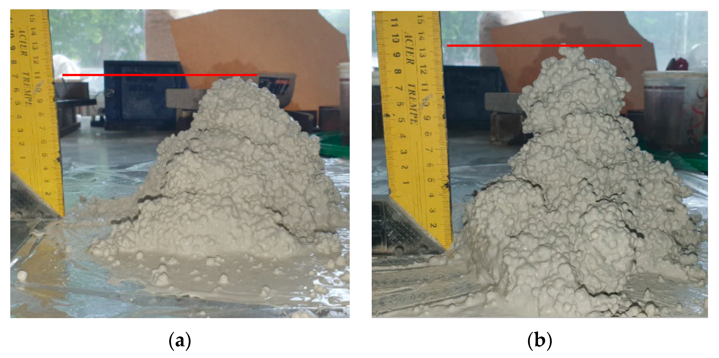
2.3. Evaluation of Material’s Suitability for 3D Printing
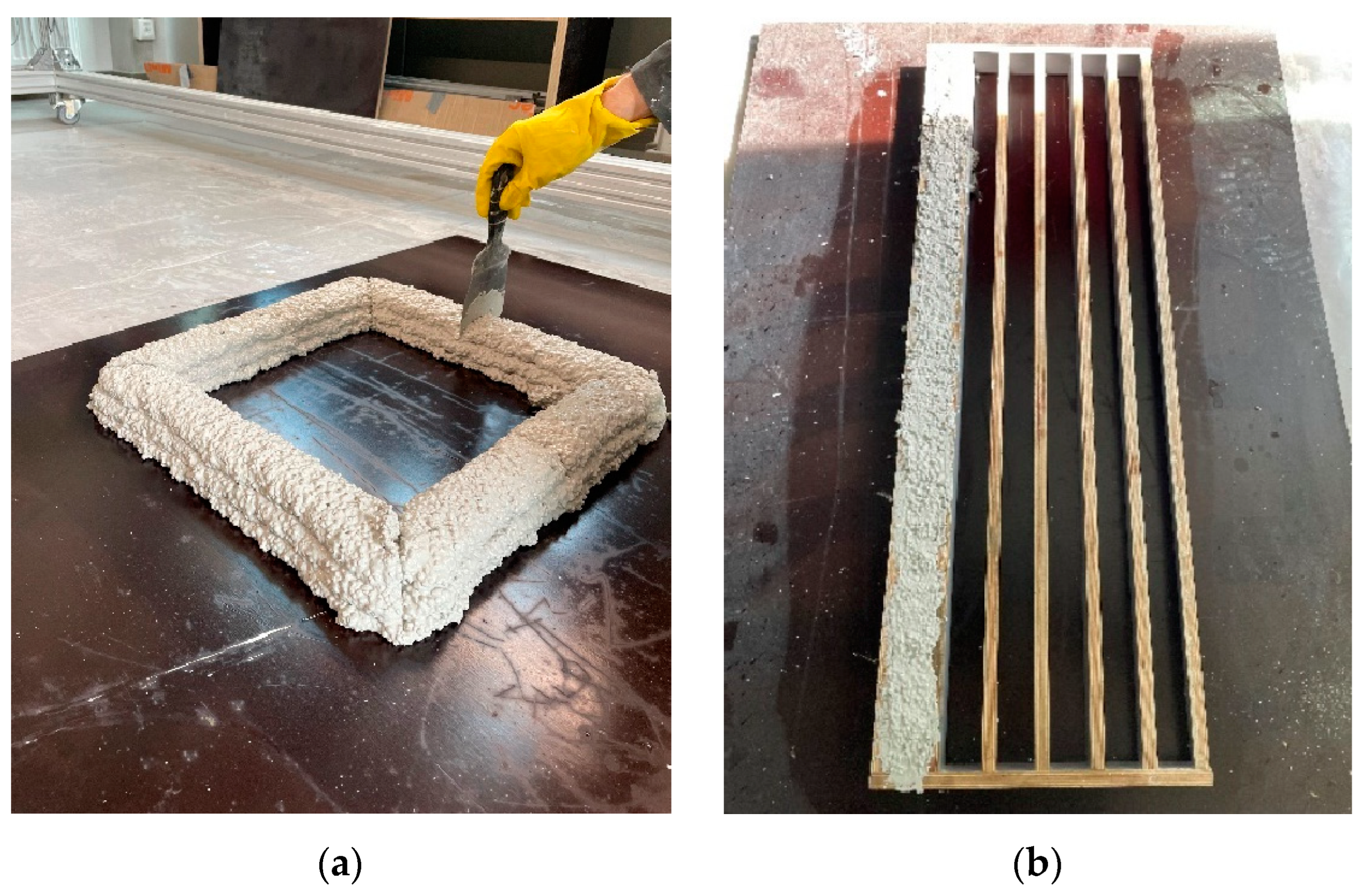
2.4. Mixing and 3D Printing
2.5. Sample Preparation
3. Results and Discussion
3.1. Fresh State Properties
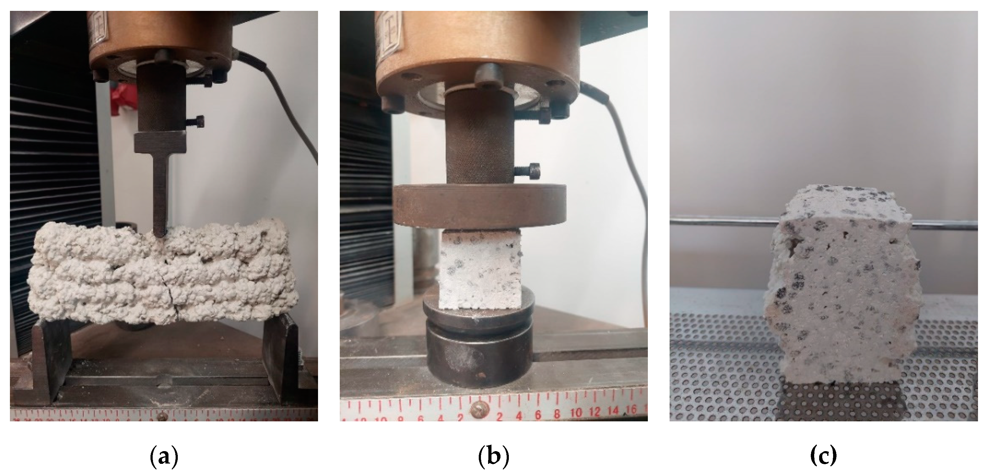
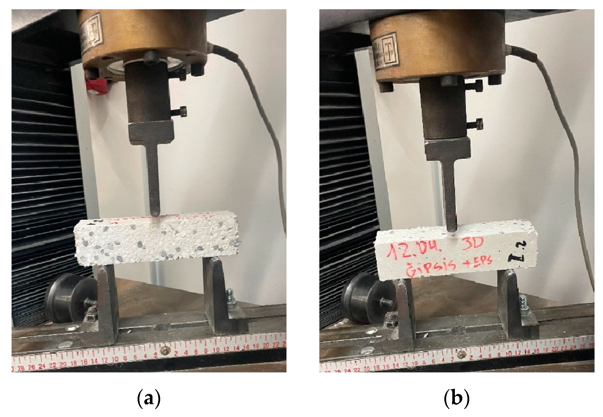
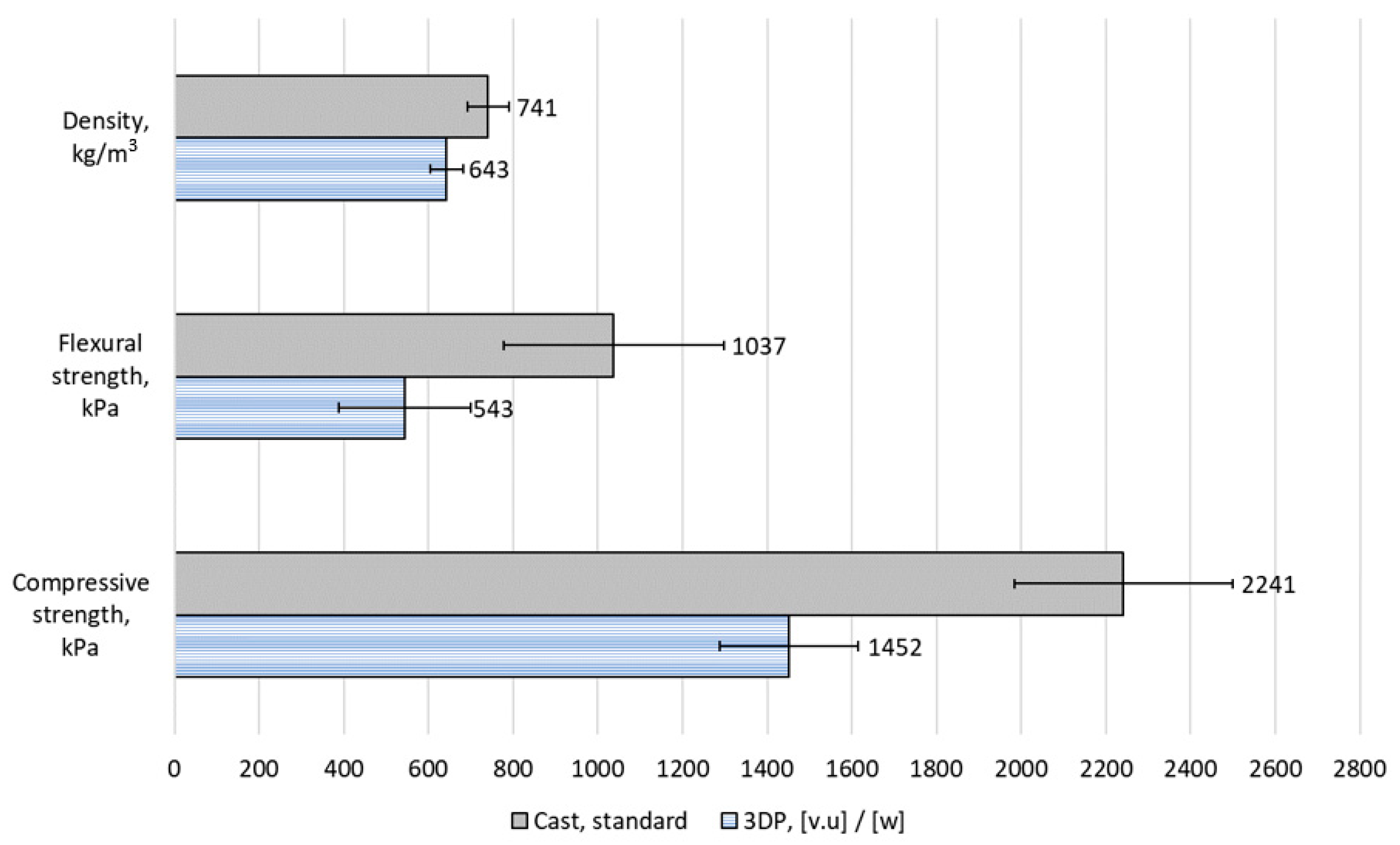
3.2. Mechanical Properties
3.3. Three-Dimensional Printing Buildability and Quality
4. Conclusions
Supplementary Materials
Author Contributions
Funding
Data Availability Statement
Conflicts of Interest
References
- Craveiro, F.; Nazarian, S.; Bartolo, H.; Bartolo, P.J.; Pinto Duarte, J. An Automated System for 3D Printing Functionally Graded Concrete-Based Materials. Addit. Manuf. 2020, 33, 101146. [Google Scholar] [CrossRef]
- Zhang, Y.; Zhang, Y.; She, W.; Yang, L.; Liu, G.; Yang, Y. Rheological and Harden Properties of the High-Thixotropy 3D Printing Concrete. Constr. Build. Mater. 2019, 201, 278–285. [Google Scholar] [CrossRef]
- Rahul, A.V.; Santhanam, M. Evaluating the Printability of Concretes Containing Lightweight Coarse Aggregates. Cem. Concr. Compos. 2020, 109, 103570. [Google Scholar] [CrossRef]
- Matthäus, C.; Back, D.; Weger, D.; Kränkel, T.; Scheydt, J.; Gehlen, C. Effect of Cement Type and Limestone Powder Content on Extrudability of Lightweight Concrete. In Proceedings of the Second RILEM International Conference on Concrete and Digital Fabrication: Digital Concrete 2020, online, 6–9 July 2020. [Google Scholar]
- Wang, L.; Jiang, H.; Li, Z.; Ma, G. Mechanical Behaviors of 3D Printed Lightweight Concrete Structure with Hollow Section. Arch. Civ. Mech. Eng. 2020, 20, 16. [Google Scholar] [CrossRef]
- Deng, Z.; Jia, Z.; Zhang, C.; Wang, Z.; Jia, L.; Ma, L.; Wang, X.; Zhang, Y. 3D Printing Lightweight Aggregate Concrete Prepared with Shell-Packing-Aggregate Method-Printability, Mechanical Properties and Pore Structure. J. Build. Eng. 2022, 62, 105404. [Google Scholar] [CrossRef]
- Mohammad, M.; Masad, E.; Seers, T.; Al-Ghamdi, S.G. High-Performance Light-Weight Concrete for 3D Printing. In Proceedings of the Second RILEM International Conference on Concrete and Digital Fabrication: Digital Concrete 2020, online, 6–9 July 2020; pp. 459–467. [Google Scholar]
- Cuevas, K.; Strzałkowski, J.; Kim, J.S.; Ehm, C.; Glotz, T.; Chougan, M.; Ghaffar, S.H.; Stephan, D.; Sikora, P. Towards Development of Sustainable Lightweight 3D Printed Wall Building Envelopes–Experimental and Numerical Studies. Case Stud. Constr. Mater. 2023, 18, e01945. [Google Scholar] [CrossRef]
- Charai, M.; Mghazli, M.O.; Channouf, S.; El hammouti, A.; Jagadesh, P.; Moga, L.; Mezrhab, A. Lightweight Waste-Based Gypsum Composites for Building Temperature and Moisture Control Using Coal Fly Ash and Plant Fibers. Constr. Build. Mater. 2023, 393, 132092. [Google Scholar] [CrossRef]
- Argalis, P.P.; Bumanis, G.; Bajare, D. Gypsum Composites with Modified Waste Expanded Polystyrene. J. Compos. Sci. 2023, 7, 203. [Google Scholar] [CrossRef]
- Bumanis, G.; Argalis, P.P.; Sahmenko, G.; Mironovs, D.; Rucevskis, S.; Korjakins, A.; Bajare, D. Thermal and Sound Insulation Properties of Recycled Expanded Polystyrene Granule and Gypsum Composites. Recycling 2023, 8, 19. [Google Scholar] [CrossRef]
- Doleželová, M.; Scheinherrová, L.; Krejsová, J.; Keppert, M.; Černý, R.; Vimmrová, A. Investigation of Gypsum Composites with Different Lightweight Fillers. Constr. Build. Mater. 2021, 297, 123791. [Google Scholar] [CrossRef]
- Çolak, A. Density and Strength Characteristics of Foamed Gypsum. Cem. Concr. Compos. 2000, 22, 193–200. [Google Scholar] [CrossRef]
- Gencel, O.; del Coz Diaz, J.J.; Sutcu, M.; Koksal, F.; Rabanal, F.P.Á.; Martínez-Barrera, G. A Novel Lightweight Gypsum Composite with Diatomite and Polypropylene Fibers. Constr. Build. Mater. 2016, 113, 732–740. [Google Scholar] [CrossRef]
- Balti, S.; Boudenne, A.; Dammak, L.; Hamdi, N. Mechanical and Thermophysical Characterization of Gypsum Composites Reinforced by Different Wastes for Green Building Applications. Constr. Build. Mater. 2023, 372, 130840. [Google Scholar] [CrossRef]
- Ding, X.; Wang, S.; Dai, R.; Chen, H.; Shan, Z. Hydrogel Beads Derived from Chrome Leather Scraps for the Preparation of Lightweight Gypsum. Environ. Technol. Innov. 2022, 25, 102224. [Google Scholar] [CrossRef]
- Bouzit, S.; Merli, F.; Sonebi, M.; Buratti, C.; Taha, M. Gypsum-Plasters Mixed with Polystyrene Balls for Building Insulation: Experimental Characterization and Energy Performance. Constr. Build. Mater. 2021, 283, 122625. [Google Scholar] [CrossRef]
- Bicer, A.; Kar, F. Thermal and Mechanical Properties of Gypsum Plaster Mixed with Expanded Polystyrene and Tragacanth. Therm. Sci. Eng. Prog. 2017, 1, 59–65. [Google Scholar] [CrossRef]
- San-Antonio-González, A.; Merino, M.D.R.; Arrebola, C.V.; Villoria-Sáez, P. Lightweight Material Made with Gypsum and EPS Waste with Enhanced Mechanical Strength. J. Mater. Civ. Eng. 2016, 28, 04015101. [Google Scholar] [CrossRef]
- Jin, Z.; Ma, B.; Su, Y.; Qi, H.; Lu, W.; Zhang, T. Preparation of Eco-Friendly Lightweight Gypsum: Use of Beta-Hemihydrate Phosphogypsum and Expanded Polystyrene Particles. Constr. Build. Mater. 2021, 297, 123837. [Google Scholar] [CrossRef]
- Spurina, E.; Sinka, M.; Ziemelis, K.; Vanags, A.; Bajare, D. The Effects of Air-Entraining Agent on Fresh and Hardened Properties of 3D Concrete. J. Compos. Sci. 2022, 6, 281. [Google Scholar] [CrossRef]
- Mechtcherine, V.; van Tittelboom, K.; Kazemian, A.; Kreiger, E.; Nematollahi, B.; Nerella, V.N.; Santhanam, M.; de Schutter, G.; Van Zijl, G.; Lowke, D.; et al. A Roadmap for Quality Control of Hardening and Hardened Printed Concrete. Cem. Concr. Res. 2022, 157, 106800. [Google Scholar] [CrossRef]
- Liu, X.; Li, Q.; Wang, L.; Wang, F.; Ma, G. Systematic Approach for Printability Evaluation and Mechanical Property Optimization of Spray-Based 3D Printed Mortar. Cem. Concr. Compos. 2022, 133, 104688. [Google Scholar] [CrossRef]
- Kloft, H.; Krauss, H.-W.; Hack, N.; Herrmann, E.; Neudecker, S.; Varady, P.A.; Lowke, D. Influence of Process Parameters on the Interlayer Bond Strength of Concrete Elements Additive Manufactured by Shotcrete 3D Printing (SC3DP). Cem. Concr. Res. 2020, 134, 106078. [Google Scholar] [CrossRef]
- Panda, B.; Chandra Paul, S.; Jen Tan, M. Anisotropic Mechanical Performance of 3D Printed Fiber Reinforced Sustainable Construction Material. Mater. Lett. 2017, 209, 146–149. [Google Scholar] [CrossRef]
- Sanjayan, J.G.; Nematollahi, B.; Xia, M.; Marchment, T. Effect of Surface Moisture on Inter-Layer Strength of 3D Printed Concrete. Constr. Build. Mater. 2018, 172, 468–475. [Google Scholar] [CrossRef]
- Nerella, V.N.; Hempel, S.; Mechtcherine, V. Effects of Layer-Interface Properties on Mechanical Performance of Concrete Elements Produced by Extrusion-Based 3D-Printing. Constr. Build. Mater. 2019, 205, 586–601. [Google Scholar] [CrossRef]
- Van Der Putten, J.; Deprez, M.; Cnudde, V.; De Schutter, G.; Van Tittelboom, K. Microstructural Characterization of 3D Printed Cementitious Materials. Materials 2019, 12, 2993. [Google Scholar] [CrossRef]
- Wang, C.; Chen, B.; Vo, T.L.; Rezania, M. Mechanical Anisotropy, Rheology and Carbon Footprint of 3D Printable Concrete: A Review. J. Build. Eng. 2023, 76, 107309. [Google Scholar] [CrossRef]
- Shakor, P.; Nejadi, S.; Paul, G. A Study into the Effect of Different Nozzles Shapes and Fibre-Reinforcement in 3D Printed Mortar. Materials 2019, 12, 1708. [Google Scholar] [CrossRef]
- Cwalina, C.D.; Harrison, K.J.; Wagner, N.J. Rheology of Cubic Particles Suspended in a Newtonian Fluid. Soft Matter 2016, 12, 4654–4665. [Google Scholar] [CrossRef]


| Mix | EPS | Baugips | Tap Water | Set Retarder | W/G |
|---|---|---|---|---|---|
| Ref-1 | 10 | 600 | 360 | - | 0.60 |
| Ref-2 | 10 | 600 | 300 | - | 0.50 |
| GR-1 | 10 | 600 | 300 | 0.1% (0.6 g) | 0.50 |
| GR-2 | 10 | 600 | 300 | 0.2% (1.2 g) | 0.50 |
| GR-4 | 10 | 600 | 300 | 0.4% (2.4 g) | 0.50 |
| Mix | Time Recorded, min | Obtained Shape | Obtained Shape after 15 Jolts | Spread Diameter, mm |
|---|---|---|---|---|
| Ref-1 | 5 |  |  | 190 |
| Ref-2 | 5 |  |  | 160 |
| GR-1 | 25 |  |  | 168 |
| GR-2 | 55 |  |  | 150 |
| GR-4 | 55 |  |  | 170 |
| Mix | EPS | Baugips | H2O | Setting Retarder | W/G | RH, % | Temperature, °C | Notes |
|---|---|---|---|---|---|---|---|---|
| GR-2 | 10 | 600 | 300 | 1.2 | 0.50 | 40 | 22 | 1 L mixed |
| GR-2b | 10 | 600 | 258 | 1.2 | 0.43 | 60 | 22 | 12 L mixed |
| GR-2c | 10 | 600 | 308 | 1.2 | 0.51 | 50 | 22 | 18 L mixed |
| Property | Time, min | Obtained Shape and Spread Diameter, mm |
|---|---|---|
| After lifting the cone | 0 | 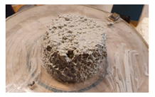 |
| After 15 jolts | 14 | 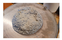 |
| After 25 jolts | 38 | 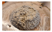 |
| Flow | 14 | 140 × 140 |
| 38 | 140 × 135 | |
| Initial setting time | - | 50 min |
| Fresh density | - | 950 kg/m3 |
| Density | Flexural Strength | Compressive Strength | ||||
|---|---|---|---|---|---|---|
| GR-2b W/G = 0.43 | GR-2c W/G = 0.51 | GR-2b W/G = 0.43 | GR-2c W/G = 0.51 | GR-2b W/G = 0.43 | GR-2c W/G = 0.51 | |
| Cast | 741 | 638 | 1037 | 1104 | 2241 | 1405 |
| 3DP [v.u]/[w] | 643 | 724 | 543 | 1175 | 1452 | 1365 |
Disclaimer/Publisher’s Note: The statements, opinions and data contained in all publications are solely those of the individual author(s) and contributor(s) and not of MDPI and/or the editor(s). MDPI and/or the editor(s) disclaim responsibility for any injury to people or property resulting from any ideas, methods, instructions or products referred to in the content. |
© 2023 by the authors. Licensee MDPI, Basel, Switzerland. This article is an open access article distributed under the terms and conditions of the Creative Commons Attribution (CC BY) license (https://creativecommons.org/licenses/by/4.0/).
Share and Cite
Bumanis, G.; Sapata, A.; Sinka, M.; Spurina, E.; Bajare, D. Additive Manufacturing of Lightweight Gypsum and Expanded Polystyrene Granulate Composite. J. Compos. Sci. 2023, 7, 425. https://doi.org/10.3390/jcs7100425
Bumanis G, Sapata A, Sinka M, Spurina E, Bajare D. Additive Manufacturing of Lightweight Gypsum and Expanded Polystyrene Granulate Composite. Journal of Composites Science. 2023; 7(10):425. https://doi.org/10.3390/jcs7100425
Chicago/Turabian StyleBumanis, Girts, Alise Sapata, Maris Sinka, Ella Spurina, and Diana Bajare. 2023. "Additive Manufacturing of Lightweight Gypsum and Expanded Polystyrene Granulate Composite" Journal of Composites Science 7, no. 10: 425. https://doi.org/10.3390/jcs7100425
APA StyleBumanis, G., Sapata, A., Sinka, M., Spurina, E., & Bajare, D. (2023). Additive Manufacturing of Lightweight Gypsum and Expanded Polystyrene Granulate Composite. Journal of Composites Science, 7(10), 425. https://doi.org/10.3390/jcs7100425