Article

Reinforced, Nailable Rubber Concrete with Strength and Withdrawal Properties Similar to Lumber

Department of Mechanical Engineering, University of South Florida, Tampa, FL 33620, USA
*
Author to whom correspondence should be addressed.
J. Compos. Sci. 2023, 7(10), 405; https://doi.org/10.3390/jcs7100405
Submission received: 2 September 2023 / Revised: 19 September 2023 / Accepted: 22 September 2023 / Published: 24 September 2023
(This article belongs to the Section Composites Manufacturing and Processing)

Abstract

:
The inclusion of rubber in concrete has been suggested and used in recent research. However, the reason for the inclusion of rubber into concrete is typically the need to offset the carbon footprint of concrete and other environmental concerns. The research presented here indicates that the inclusion of rubber into concrete allows for the concrete to accept fasteners and withstand withdrawal, or pullout, of the fasteners, similar to the function of wood. We refer to this as making the concrete “nailable”, in that the concrete can be nailed together either by hand or with tools designed to be used with wood. While other methods have been used to make concrete nailable, this method is novel as no known research exists indicating that there exists a rubber concrete mix that provides similar withdrawal strength as wood. Testing indicates that the concrete can be produced at a low cost due to the inclusion of the low-cost rubber infill with reinforcement wire. The result is a reinforced concrete with an allowable load that is 13% greater than in spruce and a withdrawal force up to 25% greater than the maximum in spruce. The intended function of this material is replacement of treated lumber. The proposed rubber concrete, which is a reinforced concrete, is anticipated to have a service life of 50–100 years, while treated lumber decks in the Southeastern United States have been surveyed to have an average life of only 10 years due to environmental degradation. This leads us to conclude that if a deck were to be constructed of this nailable rubber concrete, it would last approximately five times longer in a temperate environment, such as the Southeastern United States. This improvement can be provided at a relatively low cost while providing an alternative that both prevents the use of arsenic- and copper-containing compounds used in treated lumber and provides an additional recycling method for tires.

1. Introduction

Wood has been used throughout human history and pre-history for dwellings and other uses [1,2,3]. The relatively high strength-to-weight ratio [3,4], high stiffness [3], ease of access, and ease of workability [4] have all aided in it becoming a desirable building material.
However, wood rotting has been a continual issue in humid environments. In fact, very early humans had multiple ways of preventing wood from rotting, with some examples being ancient Egyptians using natural oils to preserve wood and ancient Greeks elevating wood from contacting the ground by placing lumber on supporting stones [5]. Preservation methods have improved over time to the present day and include the use of creosote, non-polar petrochemicals, and water-borne arsenicals, such as chromated copper arsenate (CCA) [6].
CCA-treated wood has been found to have detrimental effects on the environment due to leaching, primarily of arsenic contained within the treatment chemicals [7]. Treated lumber disposal is also a common issue in the treated wood industry. For example, in ref. [8], it is indicated that New Zealand has no effective means for the safe disposal of CCA-treated wood. This is likely an issue in many countries that do not have existing infrastructure and systems in place to dispose of CCA-treated wood. Significant efforts have been applied toward determination of life cycle assessments for lumber treatment alternatives from a health perspective [9,10]. However, CCA treatment is not the only method of treating wood against fungal and insect degradation; other treatments are possible, but these commonly contain copper-bearing chemicals, which can be damaging to aquatic environments [11].
Treated lumber, while superior to untreated lumber in exterior applications with exposure to weather, moisture, insects, fungus, etc., typically lasts for far fewer years than many other materials used for structures. For example, wood and even plastic decks typically last 10 years [12]. Saxe et al. [13] provides an excellent summary regarding the longevity of treated lumber in real-world applications. Saxe et al. concludes that Cooper [14] indicates the following: researchers determined that CCA-treated wood has a 50-year service life, which caused Saxe et al. to assume that a 25-year service life was appropriate. However, in ref. [15], it is asserted that when 527 decks were replaced based on years of service, it was determined that the average age of disposal in the Southeastern United States was only 9 years, with a standard deviation of 5 years. Ref. [16] surveyed 580 contractors in the Southeastern United States, and it was found that decks were demolished after 13 years, on average. Saxe et al. [13] suggests that an average deck life of 10 years is an appropriate assumption when discussing a deck constructed from CCA-treated wood.
However, by using a low-cost rubber concrete with steel reinforcement, the unique properties of wood may be approximated such that the concrete can be installed using fasteners designed for use in wood, which is a concept postulated and tested in this research. This may allow for a concrete that functions as a drop-in replacement for wood but with superior longevity in wet environments. For example, properly designed reinforced concrete structures can have a service life of 50 years and, if using corrosion-resistant steel, up to 100 years, even in harsh environments [17].
Rubber tires and their proper end-of-life use have been an ongoing global issue; this is often referred to as a crisis due in large part to the non-degradability of tires [18]. The large quantities of tires produced globally cause environmental hazards [19]. The current primary disposal methods for waste rubber are combustion as fuel, burying of the rubber in landfills, and regenerating the rubber to be reused as tires [20]. The addition of recycled rubber from tires to concrete mixes is a widely researched topic [21]. While rubber is known to weaken concrete due to lack of cohesion between the rubber and concrete, it can still exhibit mechanical strength comparable to more typical concretes at up to 20% rubber substitution for aggregate [22]. More recent articles, such as ref. [23], indicate that the strength of a rubber concrete mix can be improved through the addition of silica fume and fly ash replacing cement.
Recycled rubber tires have also found use as ground tire rubber applied to asphalts. This use of ground tire rubber may prove to be superior in certain climates, such as the wet and cold climates of Michigan [24,25,26].
The technology proposed in this paper suggests that two problems can be solved simultaneously regarding environmental issues; that is, an effective use of waste tires can be provided resulting in a structural element that can function as a replacement for treated lumber. This could address the global tire recycling problem and the release of arsenic and other chemicals from treated wood. Therefore, while most technologies focus on fixing a single environmental issue, this technology has the potential to address two issues simultaneously.
The terminology of a “nailable” concrete has been proposed before. For example, ref. [27] presents a patent for nailable concrete. Such concretes, however, functioned through the use of materials different from those proposed here. Ref. [27] indicates that a combination of exfoliated mica and vitrified clay work to provide concrete with nailability. Additionally, there exists a magazine article (ref. [28]) that indicates that nailability can be attained by the inclusion of sawdust into a concrete mix. Other mentions of “nailing” concrete can be found in refs. [29,30,31,32], which refer clearly to the use of rubber concrete for architectural applications, a notable distinction from what is proposed here.
The concept presented here is that a concrete can have both reduced nail insertion force and increased nail withdrawal, or pullout, strength through the inclusion of rubber into the concrete mix. While other nailable concretes do exist in earlier research, the use of a common, low-cost rubber is not previously known to have been possible as prior examples use mica, talc, or wood pulp.
To test these properties, the research presented here focuses on verifying that the strength of the developed concrete mix, which includes a high infill of crumb rubber, can be provided in such a way that it meets strength requirements that are comparable to wood. As wood construction commonly involves the use of mechanical fasteners, it is appropriate to test the most commonly used mechanical fasteners by physically inserting these fasteners into the concrete samples and withdrawing them, measuring the force required to withdraw the mechanical fastener.

2. Design Intention

This paper focuses on a unique concrete mix. The design intention for this mix is a material that can be produced at a low cost and comparable strength to wood-type materials while providing increased longevity and the same or similar fastening techniques. We feel this is necessary, as it provides a substantial advantage over alternative materials. There is a gap in materials that properly fill the niche of
  • Low cost compared to other wood alternatives.
  • Fast and known installation methods (similar to wood construction).
  • Increased longevity compared to wood.
  • Use of recycled infill to reduce carbon footprint of the material.
  • Material that is more resilient to ignition from fire compared to wood.
  • Material that readily accepts paint with minimal preparation.
  • Material that poses less environmental risk than treated wood.
Therefore, while the material itself may not have an obvious use case when compared to reinforced concretes, the material does have a use case when used as an alternative for treated lumber.
To clarify, by treated lumber we mean the regularly available material. Within the United States of America, there are various grades of treated lumber, with standards controlled by the American Wood Protection Association (AWPA), which typically feature chemicals applied to the wood to reduce damage due to fungal, insect, and other sources.

2.1. Design Methodology

While there are multiple potential reasons for the inclusion of rubber into a concrete, it was our goal to increase the friction of fasteners driven into the concrete while maintaining a lower driving force. As the addition of rubber to concrete often decreases the strength of the concrete mix, rubber is known to have a high frictional coefficient value when comparing the static friction of material.
For example, one potential equation for nail withdrawal (typically referred to as pullout within the concrete industry) strength in wood can be expressed as (see ref. [33])
F = μ π D L σ c + σ c ,
where μ is the frictional coefficient, D is the diameter of the nail, L is the fastener length within the material, σc‖ is the compressive strength parallel to the grain, σc is the compressive strength perpendicular to the grain, and F is the withdrawal strength.
For a concrete mix, we can assume that the compressive strength parallel and perpendicular to the grain is similar. This equation suggests that there is a direct relationship between the frictional coefficient between the steel of the nail and the wood that is directly proportional to the withdrawal (pullout) strength of the material.
Additionally, as mentioned in the introduction section, there is commonly a direct relationship between the percentage of included rubber and the reduction in strength of a concrete. While not directly proportional, it can be suggested that this increase in rubber content decreases compressive strength. This is key to developing a concrete mix that can have nails driven into it using minimal force.
The attempt to increase this frictional value resulted, in our study, in rubber concrete mixtures. The ideal situation is to decrease the force required to drive a nail while increasing the force required to remove the nail. Rubber concrete mixtures can be produced that fit these requirements, allowing the rubber concrete emulation of the properties of wood that allow its installment with quickly applied mechanical fasteners.

2.2. Practical Applications

The primary practical applications for the nailable rubber concrete typically involve end use in applications where the material can be used most effectively. Here are the key improvements this material provides from an application perspective:
  • Applications where exposure to water is possible.
  • Applications where exposure to biological damage (fungal, insect, etc.) is possible.
This would produce the following primary applications:
  • Exterior wood applications, such as decks, fences, walls, open structures, agricultural structures, etc.
  • Interior wood applications where exposure to water is possible, such as bathrooms, kitchens, and bottom or toe boards in stud wall construction methods.
It should be noted that, as this concrete has the potential for a workability similar to wood, the potential end uses can be considered to be nearly as ubiquitous as those of wood.

3. Materials and Methods

For the materials and methods section, we review the concrete mixture we are detailing in this study, the methods of manufacturing the samples (including the reinforcement), the apparatuses used for testing the bending moment and the pullout or withdrawal strength, and the ways in which we tested the nail insertion strength.

3.1. Concrete Mixture

This paper uses the concrete mix shown in Table 1. This is a single mix that was found, qualitatively, to function as intended. Superior mixes that increase or decrease certain properties are likely to exist that can be developed for specific applications. Therefore, it is expected that this research will lead to many other improved concrete mixes that utilize the inclusion of rubber to allow for nail withdrawal strength similar to that of wood.
The water-to-cement ratio was maintained at 30% on a mass ratio basis. This resulted in a clay-like texture. The sand used was Sakrete Multi-Purpose sand, a coarse construction sand, with 1% passing a 45 micron sieve and a soluble silica content of 1.8+/−0.3% [34]. Portland cement that was used was ordinary, type I/II Portland cement manufactured by Sakrete. The properties of this cement can be found in ASTM C150. Plasticizers and superplasticizers were not applied to the concrete mixes in this study.
By reviewing the mix shown in Table 1, it was found that this concrete contains high portions of Portland cement by mass. However, the volumetric ratios are much higher for the crumb rubber. To show this, Figure 1 below is provided. As the density of rubber is much lower than that of the other components, the resulting mixture volumetrically contains more crumb rubber than may be assumed.
The concrete mixtures tested contained no rock. Rock was excluded from the mixture as a coarse aggregate may interrupt the proper driving of fasteners in the material, causing the fastener to strike a large, hard component such as stone.
The crumb rubber used was recycled crumb rubber with a 5–10 mesh size. The rubber was soaked in water for at least 24 h prior to mixing into the concrete.
Due to the small sample size, concrete was mixed by hand in a small bucket until homogeneous. We mixed larger samples using a standard, drum-type concrete mixer, but those samples are not presented here.

3.2. Reinforced Concrete Sample Manufacturing

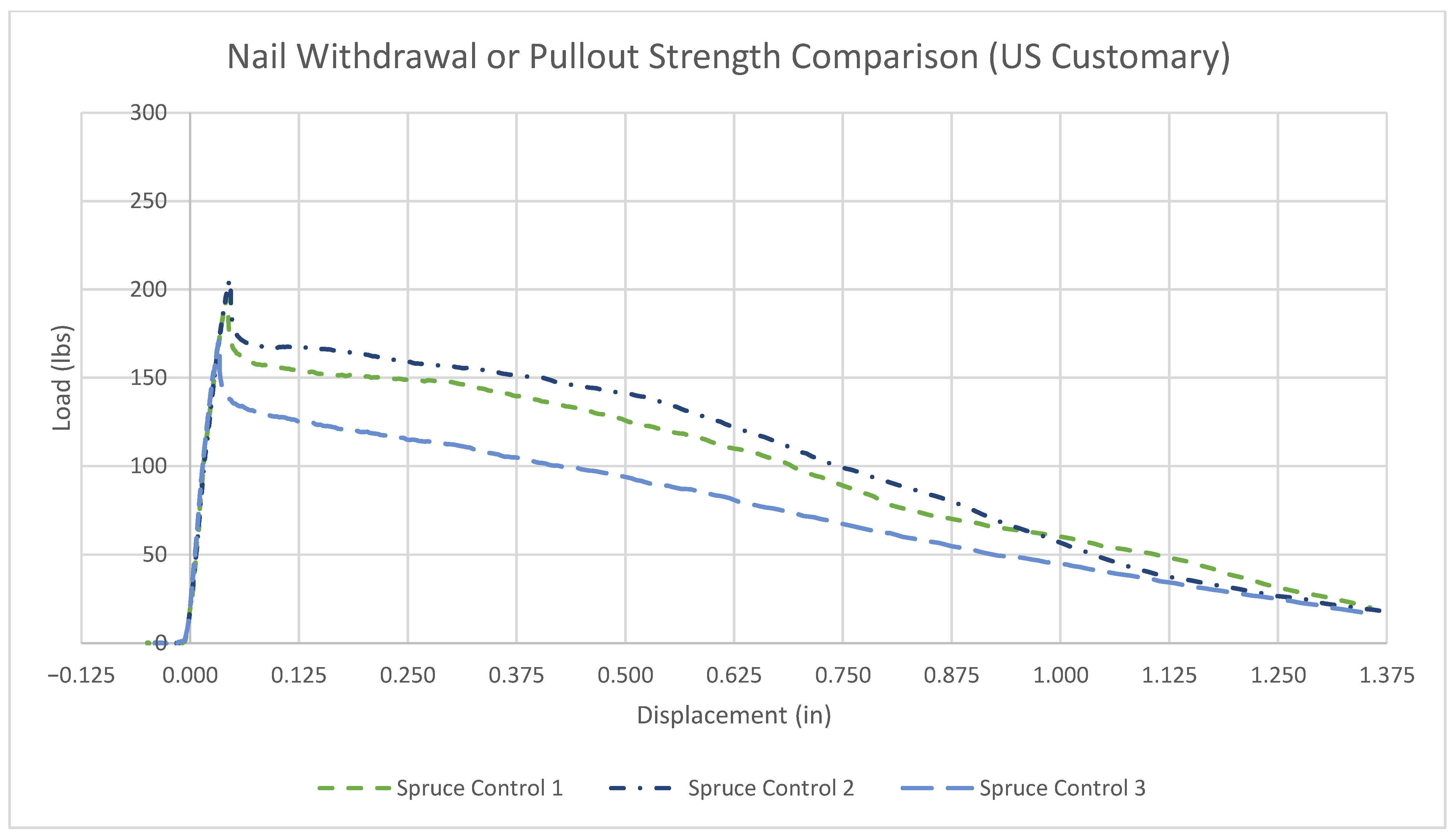
Samples were created and tested against a wood beam of the same exterior dimensions. The beams created for these tests had the following properties:
  • Beam width: 38.1 mm (1.50 inch),
  • Beam depth: 41.3 mm (1.63 inch),
  • Concrete cover: 3.2 mm (0.13 inch).
Reinforcement was spaced according to the necessary cover and beam dimensions. As such, and due to the relatively small size of the samples, smaller reinforcement had a larger effective spacing when measured between the centerlines of longitudinal reinforcement.
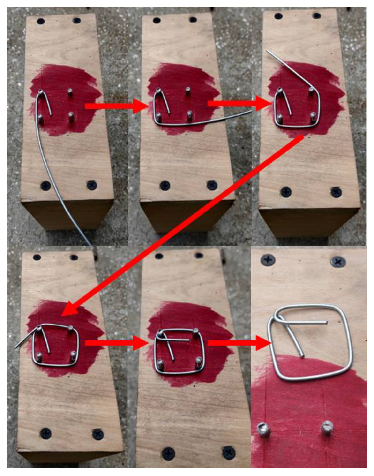
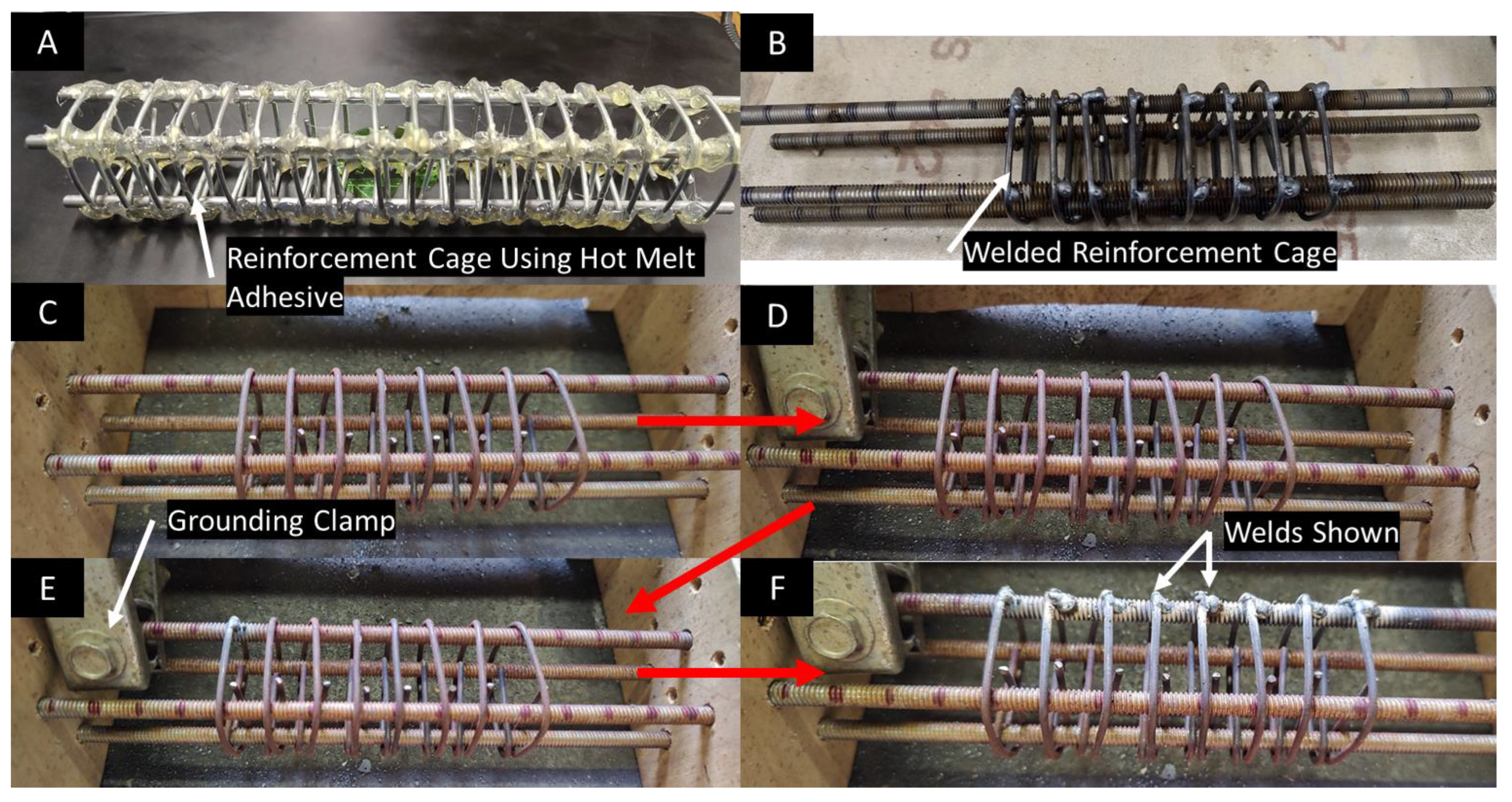
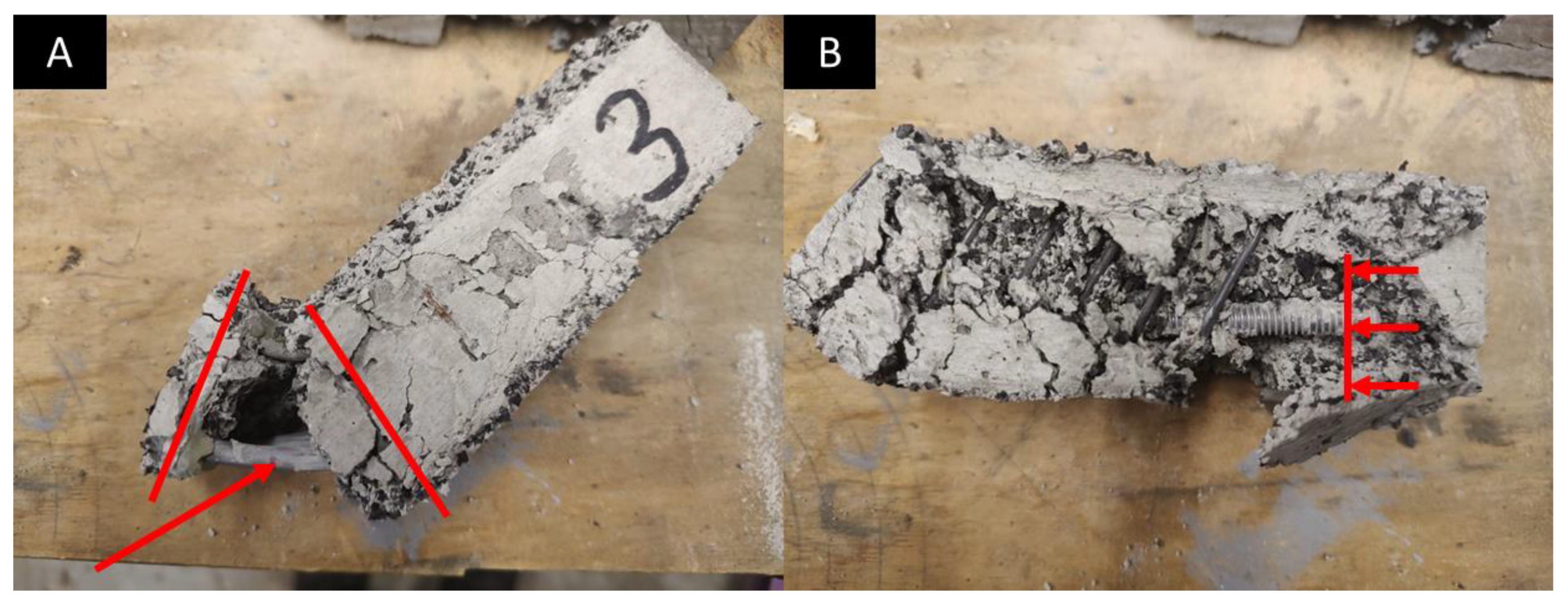
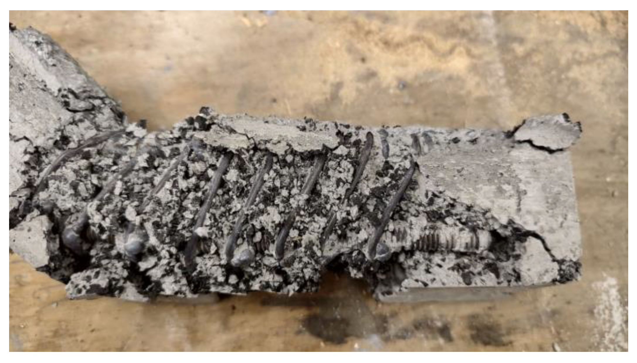
Different attempts were made to provide shear reinforcement for the concrete samples. Due to the small size of the samples, the method that was found to work most correctly was the use of small ties that were individually bent by hand and slid into place using a manufacturing jig. An example of the bending method is shown in Figure 2.
The shear reinforcement wire used was 2.0 mm (0.08 inches) in diameter and composed of low-carbon 1006–1008 steel with annealed heat treatment and a yield strength of 483 MPa (70,000 psi).
Several different reinforcement types and attachment methods were attempted. In some configurations, off-the-shelf hot melt adhesive (HMA) was used as an alternative to welding the wire reinforcement. Due to the small size of the reinforcement, some more common methods did not work. HMA was attempted due to the assumed low load conditions as the beams were intended to be low cost. As described later, welding of the shear reinforcement proved to be significantly superior from a bending moment strength perspective.
A cage connected using HMA is shown in Figure 3A, while a welded cage is shown in Figure 3B. Note that the process shown in Figure 3C–F must be repeated four times before the wire cage can be removed. After removal, the remaining shear reinforcement was installed and welded in the same way. The jig is necessary to guarantee alignment during the initial welding. A MIG welder was used to create the welded cages. The MIG welder used was an HYL MIG180Y welder. The welding wire was E71T-11, 0.030″ (0.76 mm) Gasless Flux Cored MIG Wire.
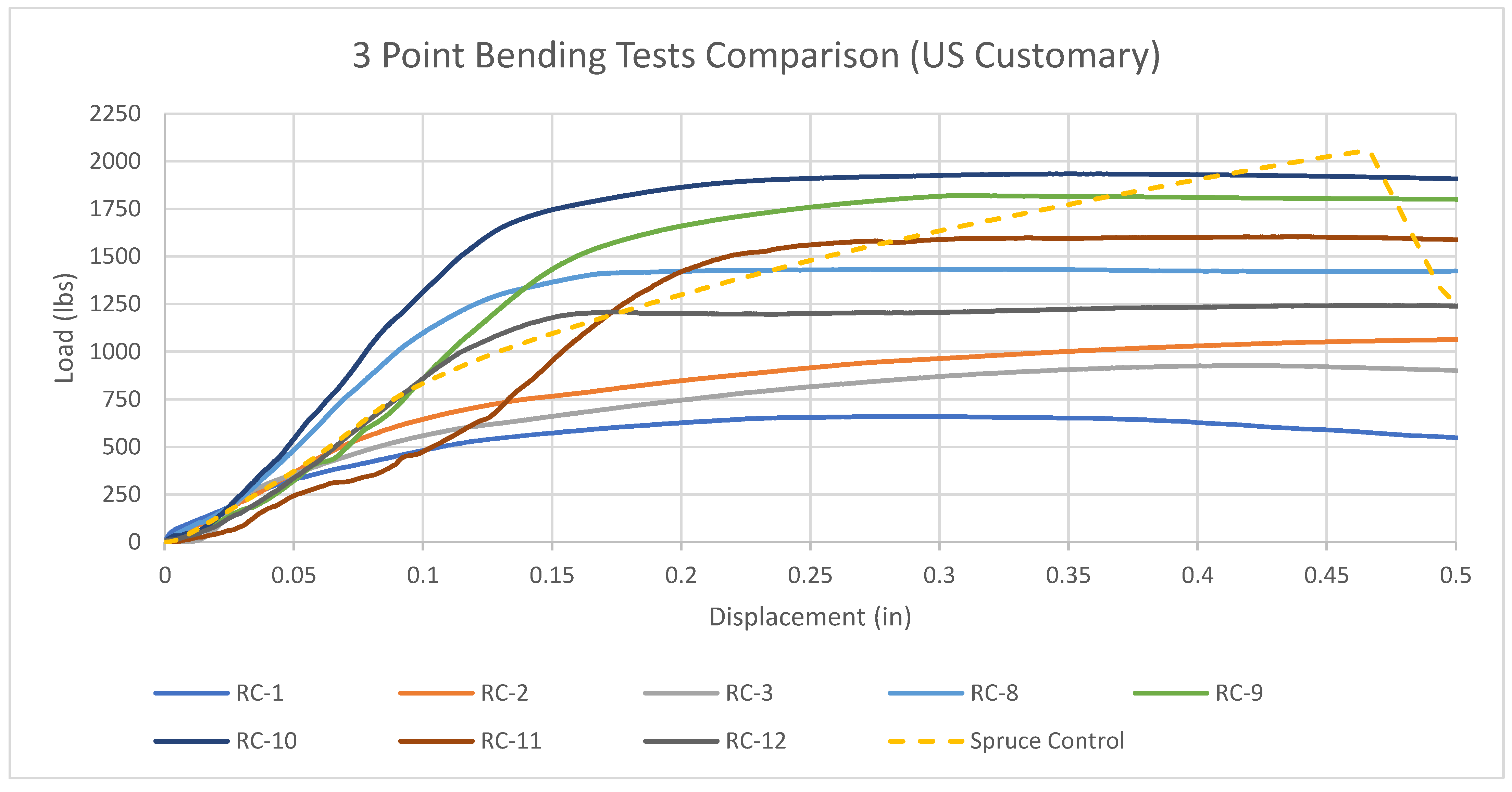
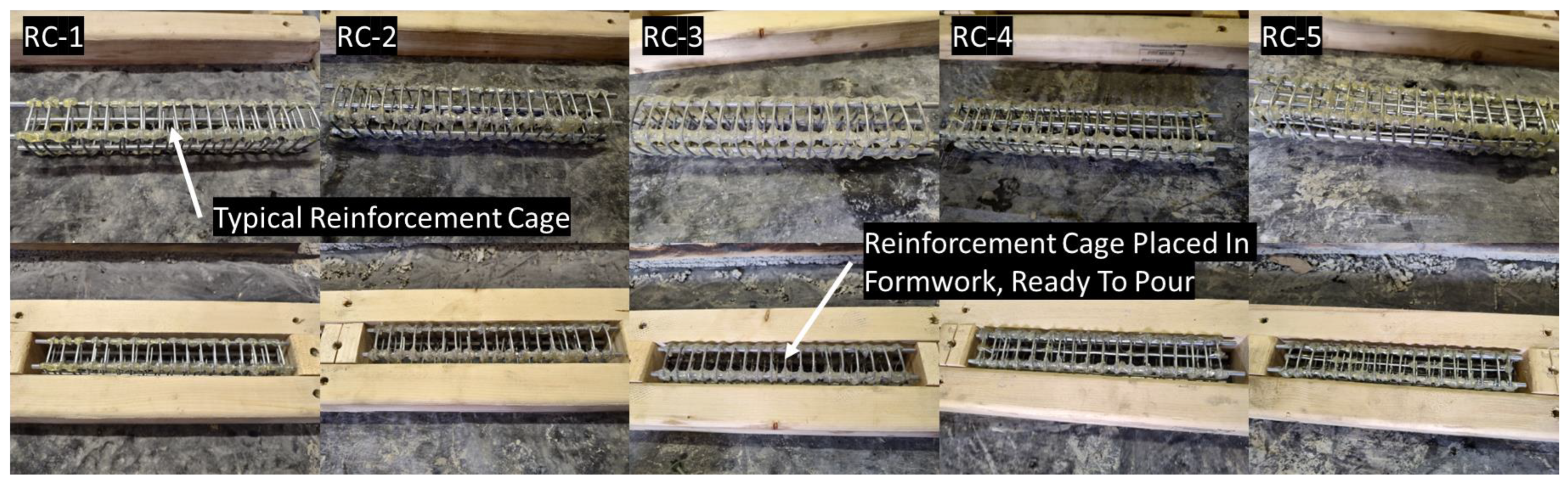
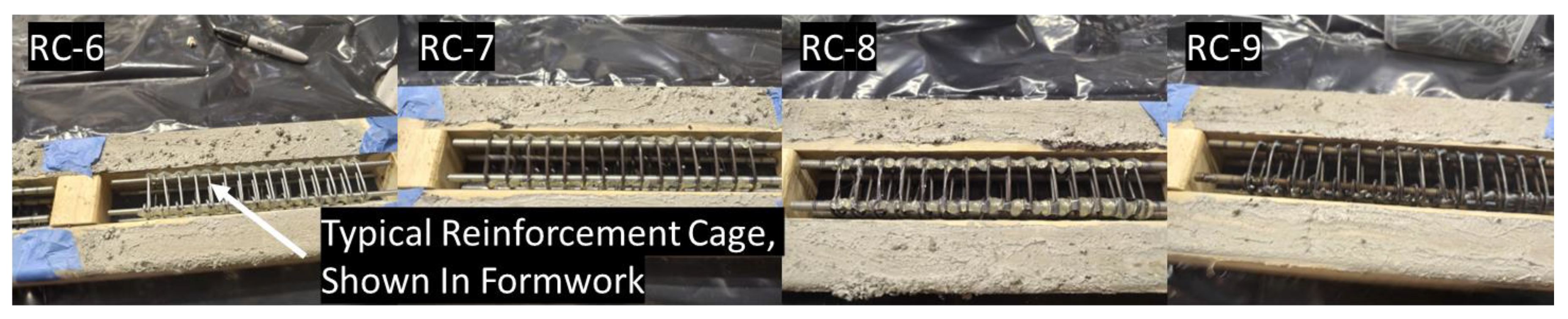
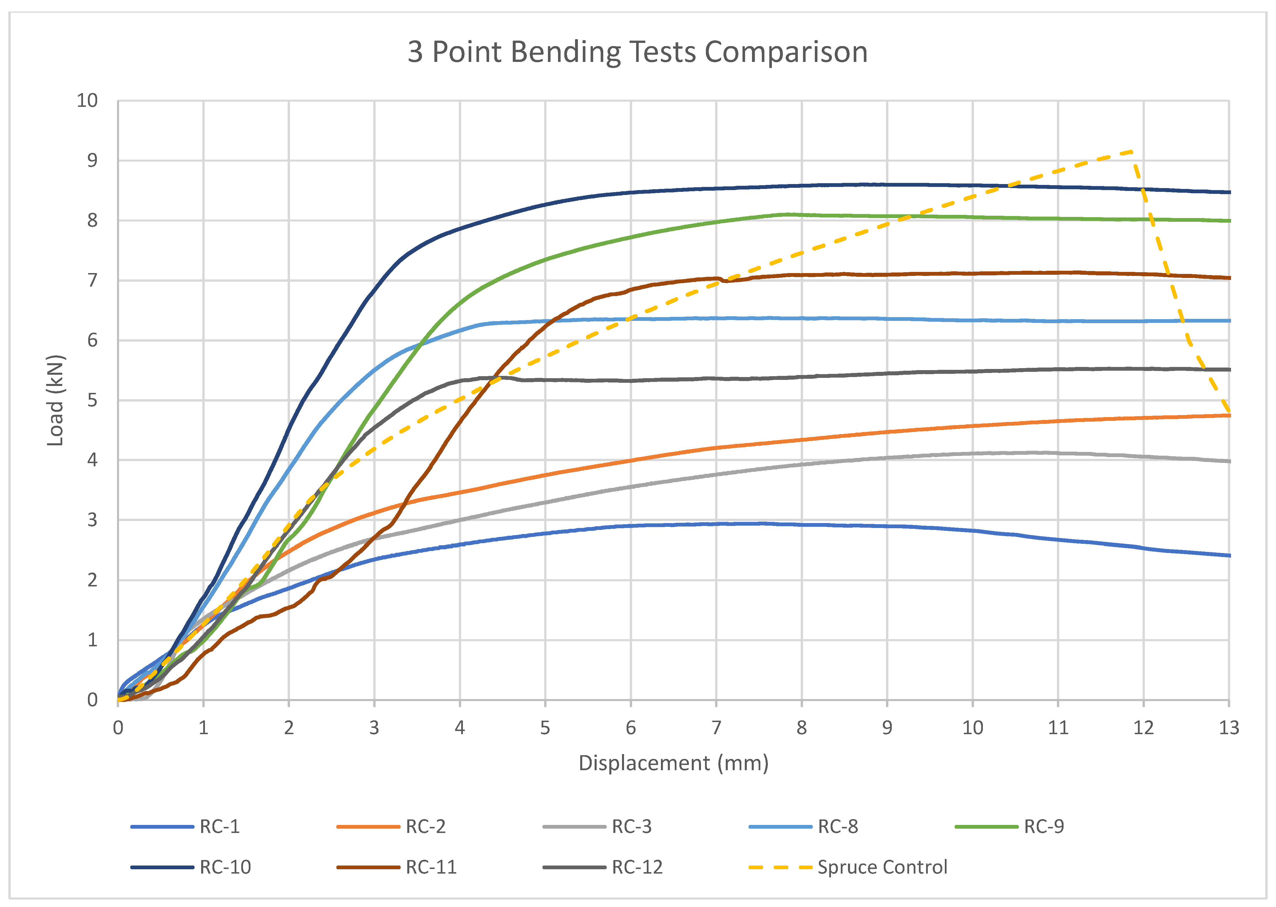
Beams are denoted as RC (nailable rubber concrete). Beams RC-1 through RC-5 are shown before casting in Figure 4 below. These beams were attached using HMA. Figure 5 shows beams RC-6 through RC-9.
The repeated process is shown in Figure 5, but this includes the beam with welded reinforcement, RC-9.
Due to the sample beams having many configurations, Table 2 shows the testing conditions of each beam.

3.3. Apparatuses

An MTS 858 Universal Testing Machine was used for all tests. The different components utilized while operating the machine are indicated in Table 3 below. This table includes model numbers and information regarding each component.
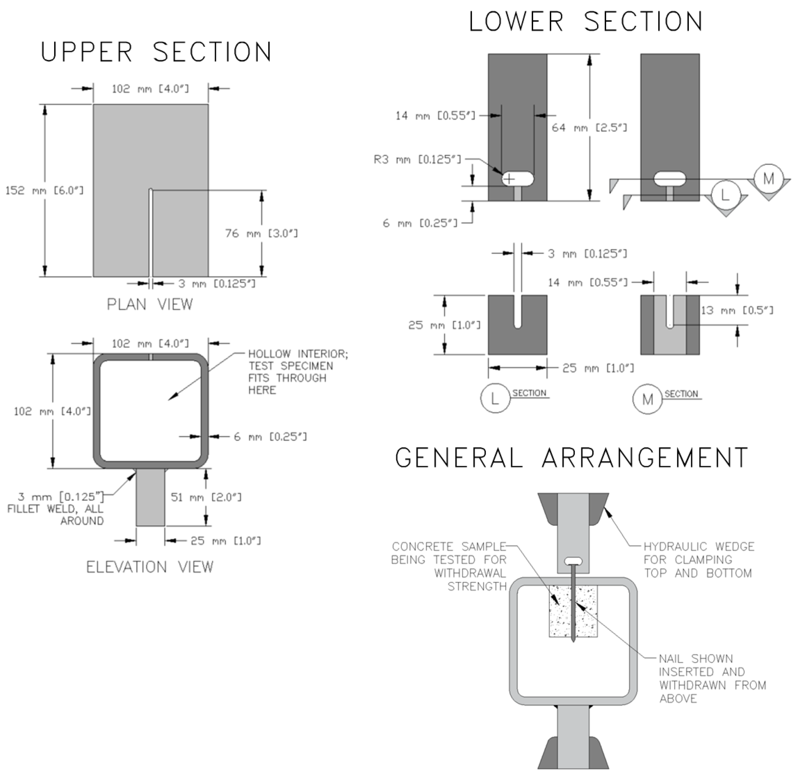
Due to the lack of accessibility to a nail withdrawal testing system, a testing apparatus had to be constructed for the pullout or withdrawal tests. Note that this apparatus is representative of devices typically used for conducting nail withdrawal tests according to ASTM D1037. Figure 6 shows detailed drawings on how the nail withdrawal apparatus was constructed.
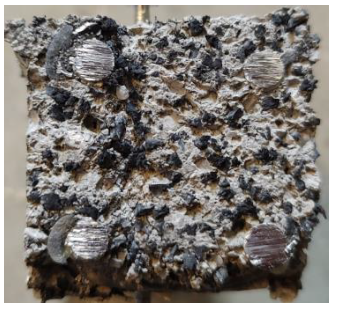
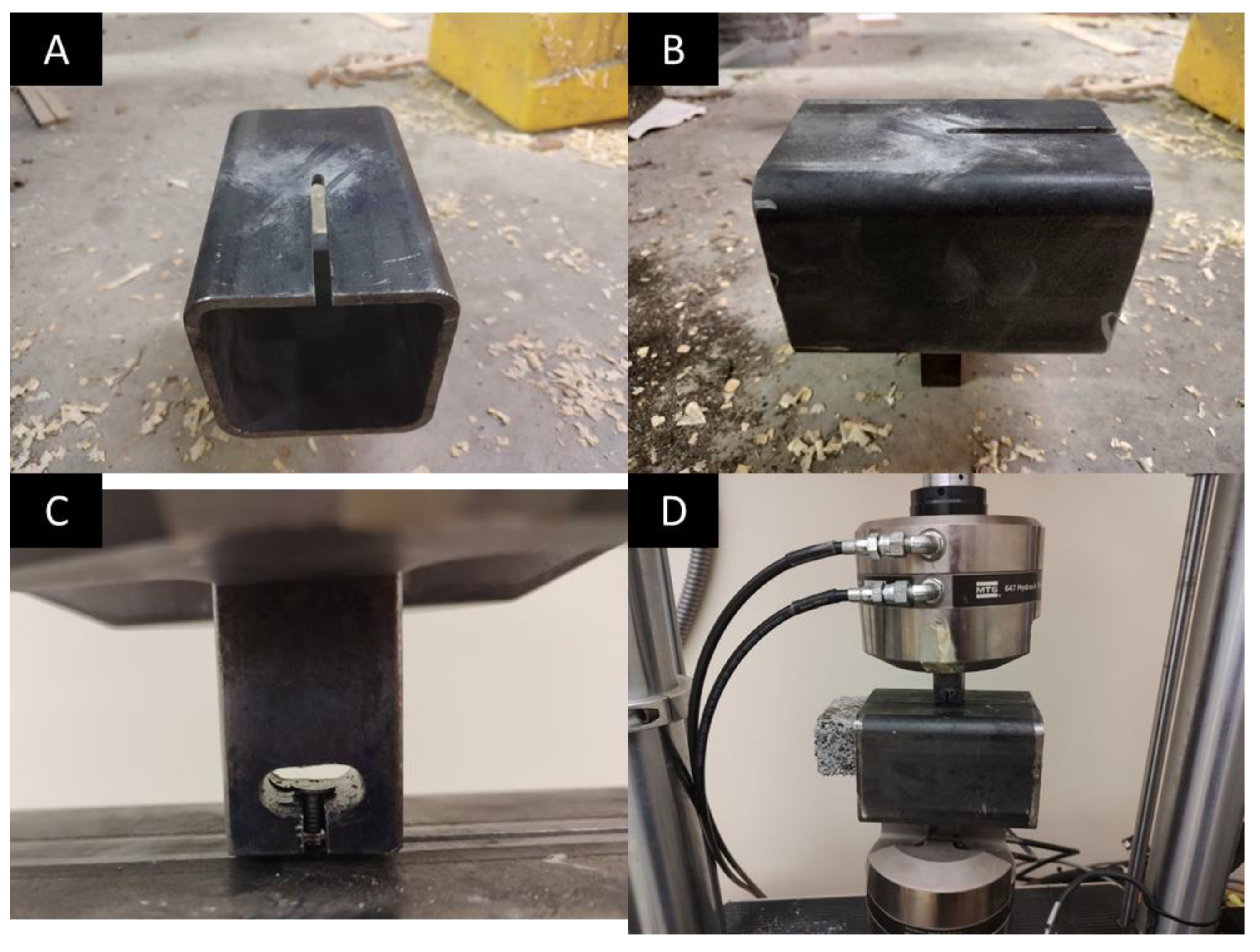
Figure 7A,B show the lower section of the withdrawal device. To simplify construction, a section of hollow, square, structural steel was purchased. The section shape was 102 mm × 102 mm × 6.3 mm (4 inches × 4 inches exterior dimensions with a 0.25-inch thickness). A 3 mm (0.125 inch) slot was milled into the shape, halfway through. A sample was placed inside the device with a nail protruding. The head was slipped into the device as shown in Figure 7C so that the MTS 858 could withdraw the fastener, as shown in Figure 7D.

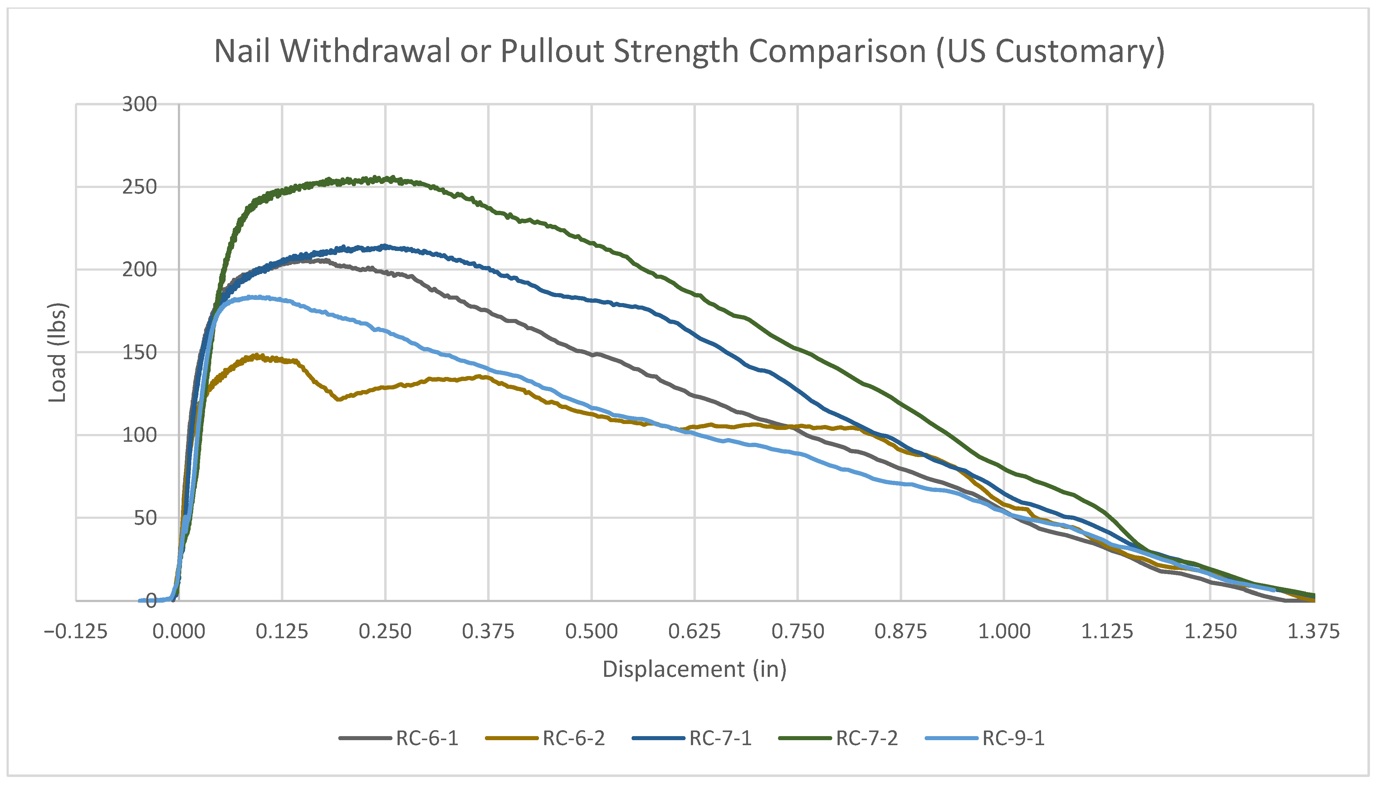
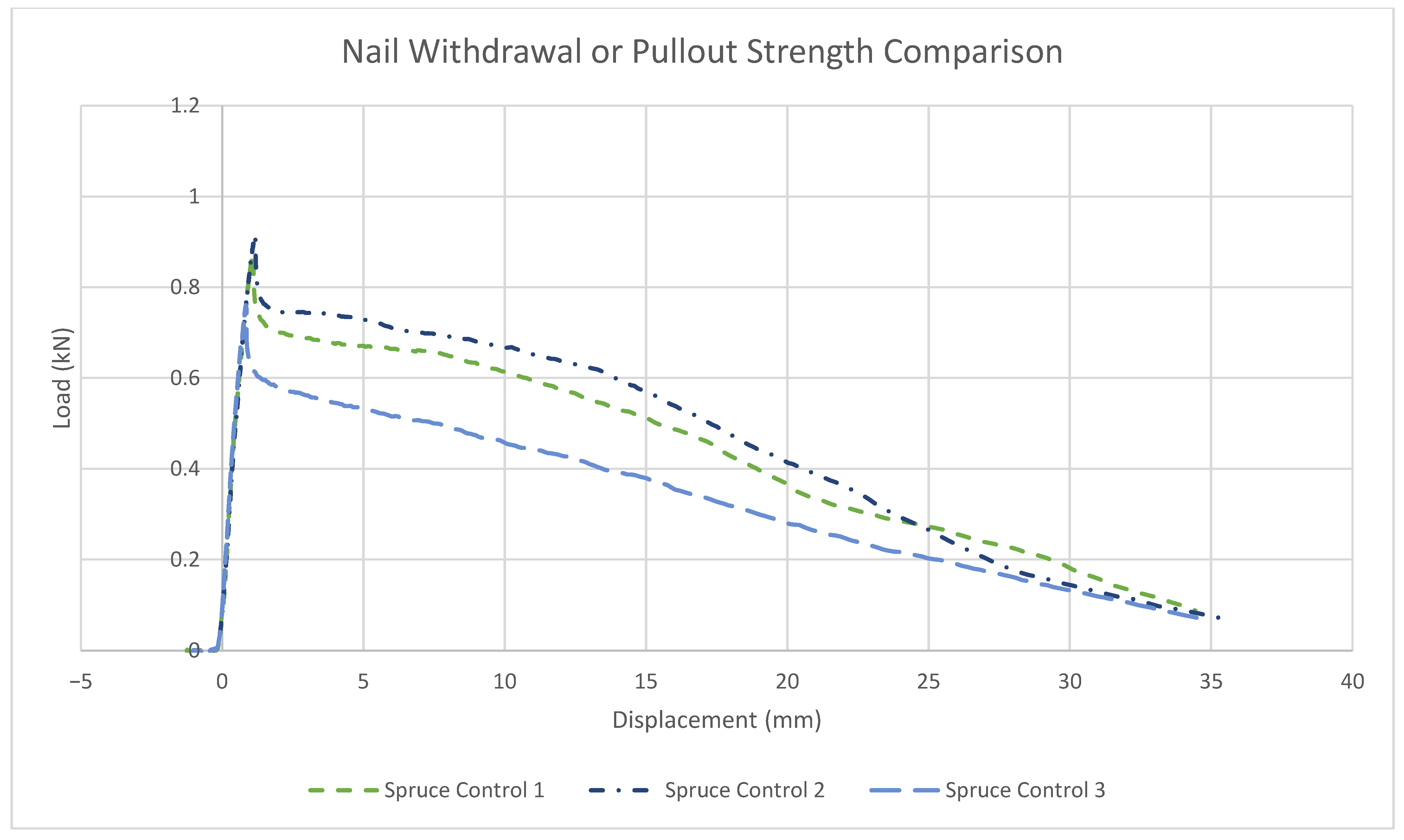
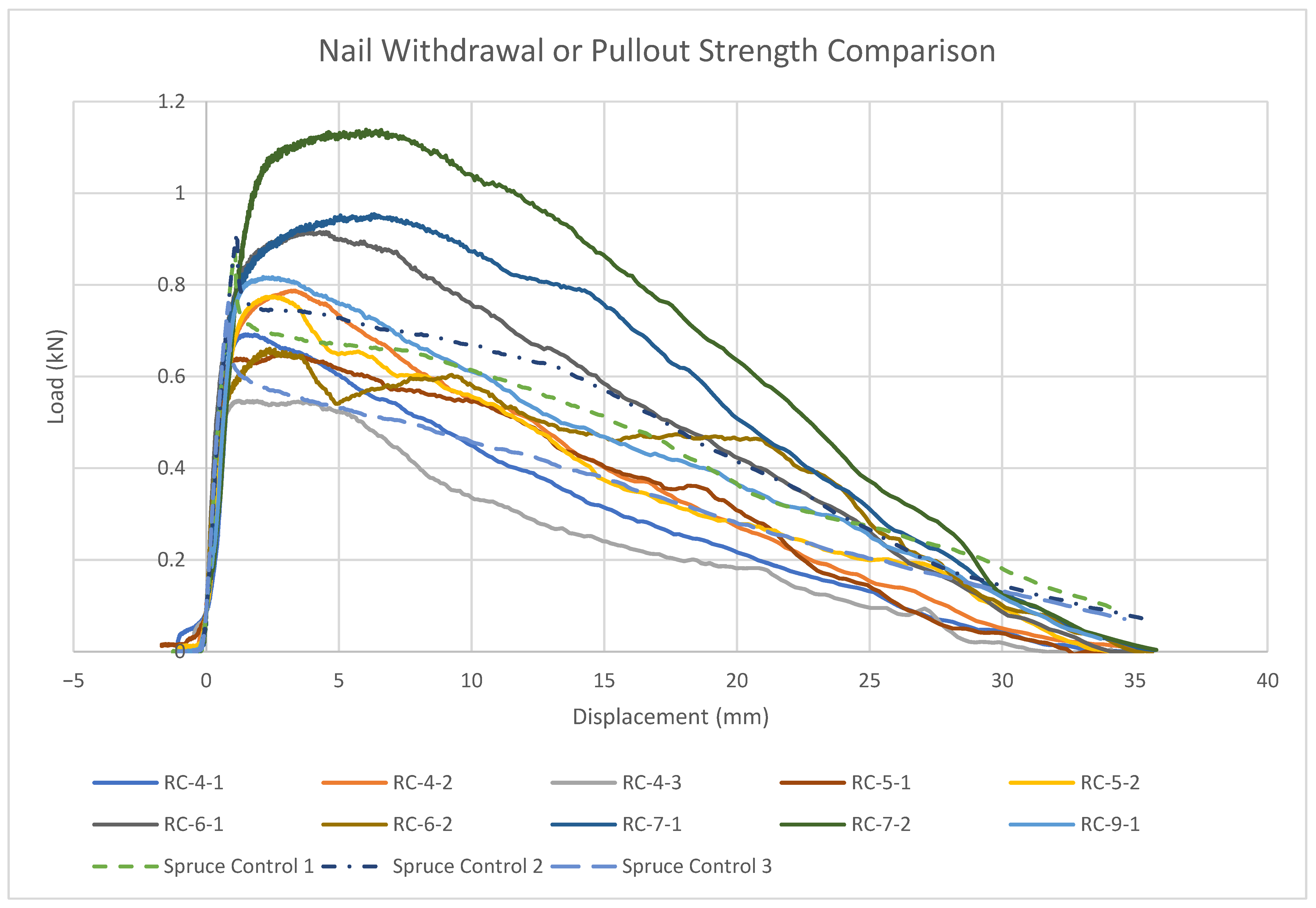
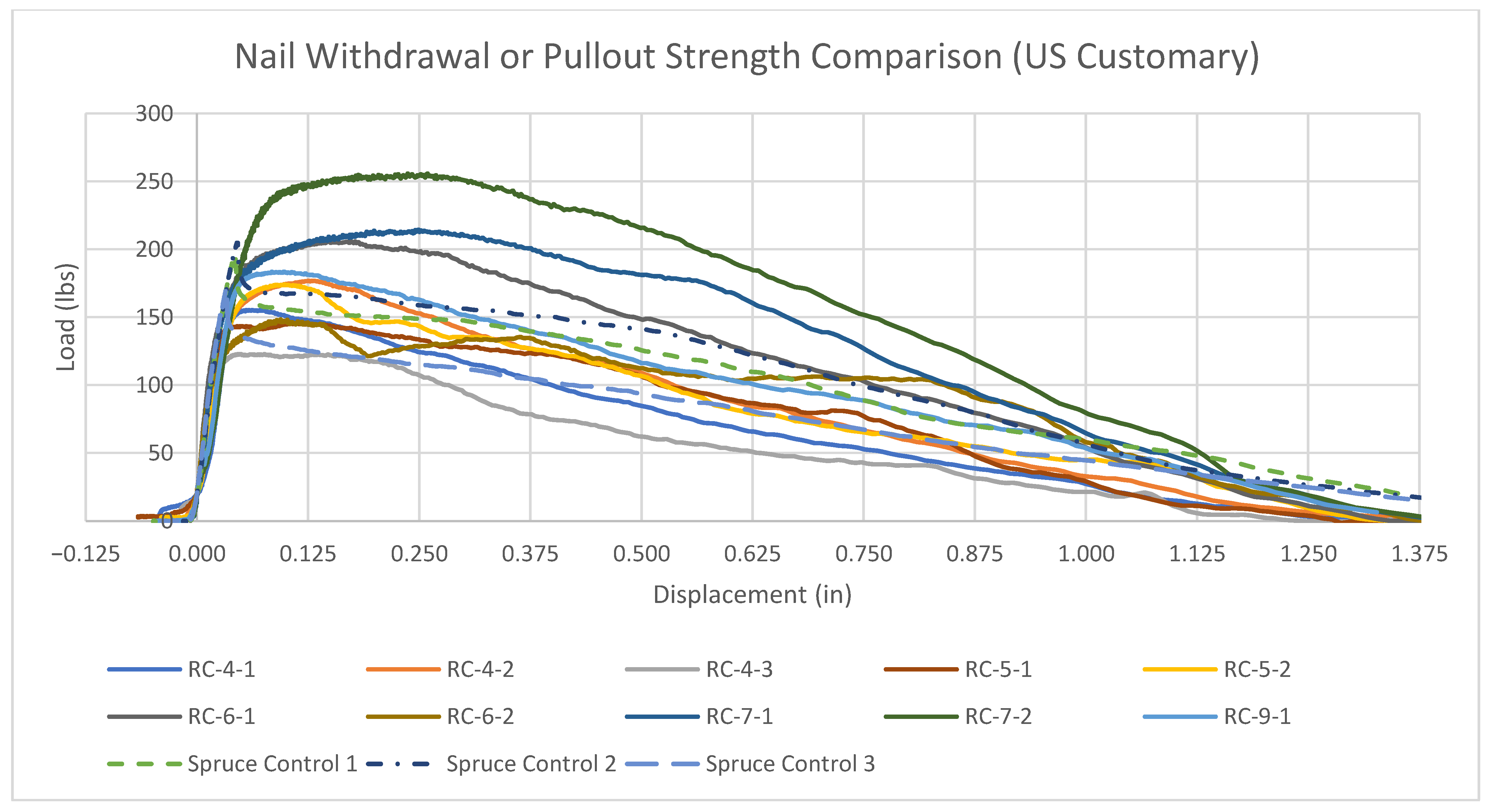
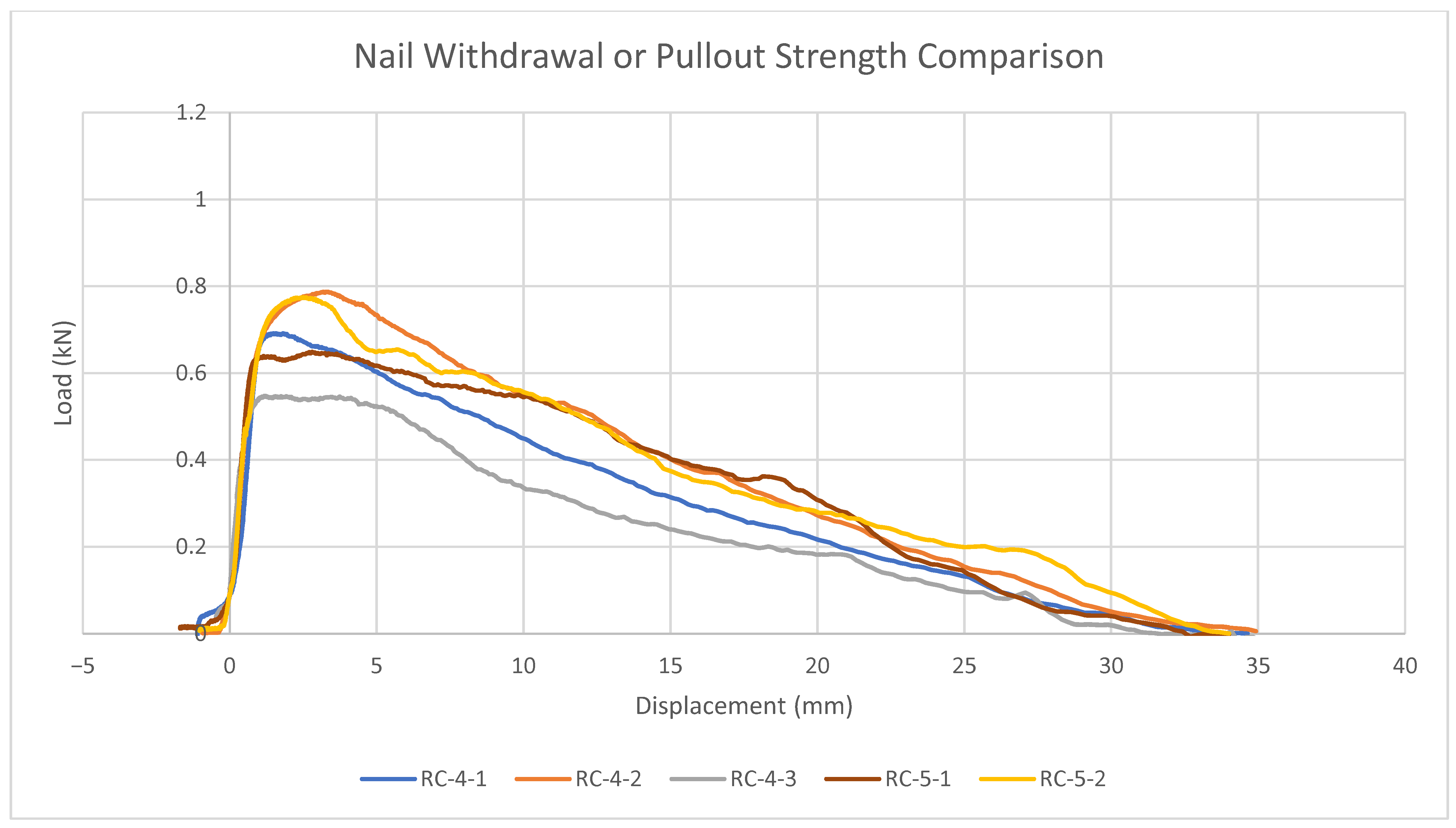
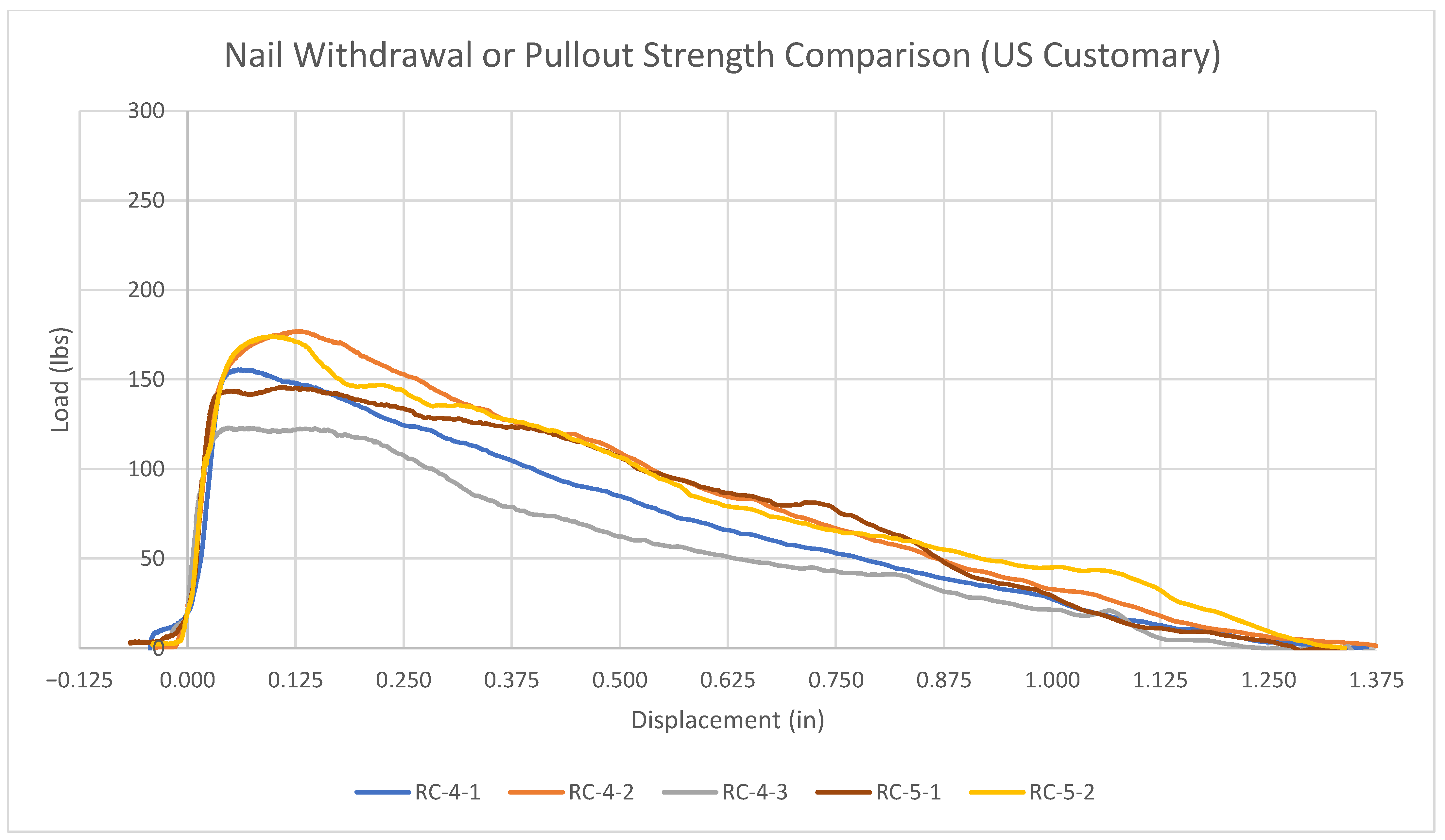
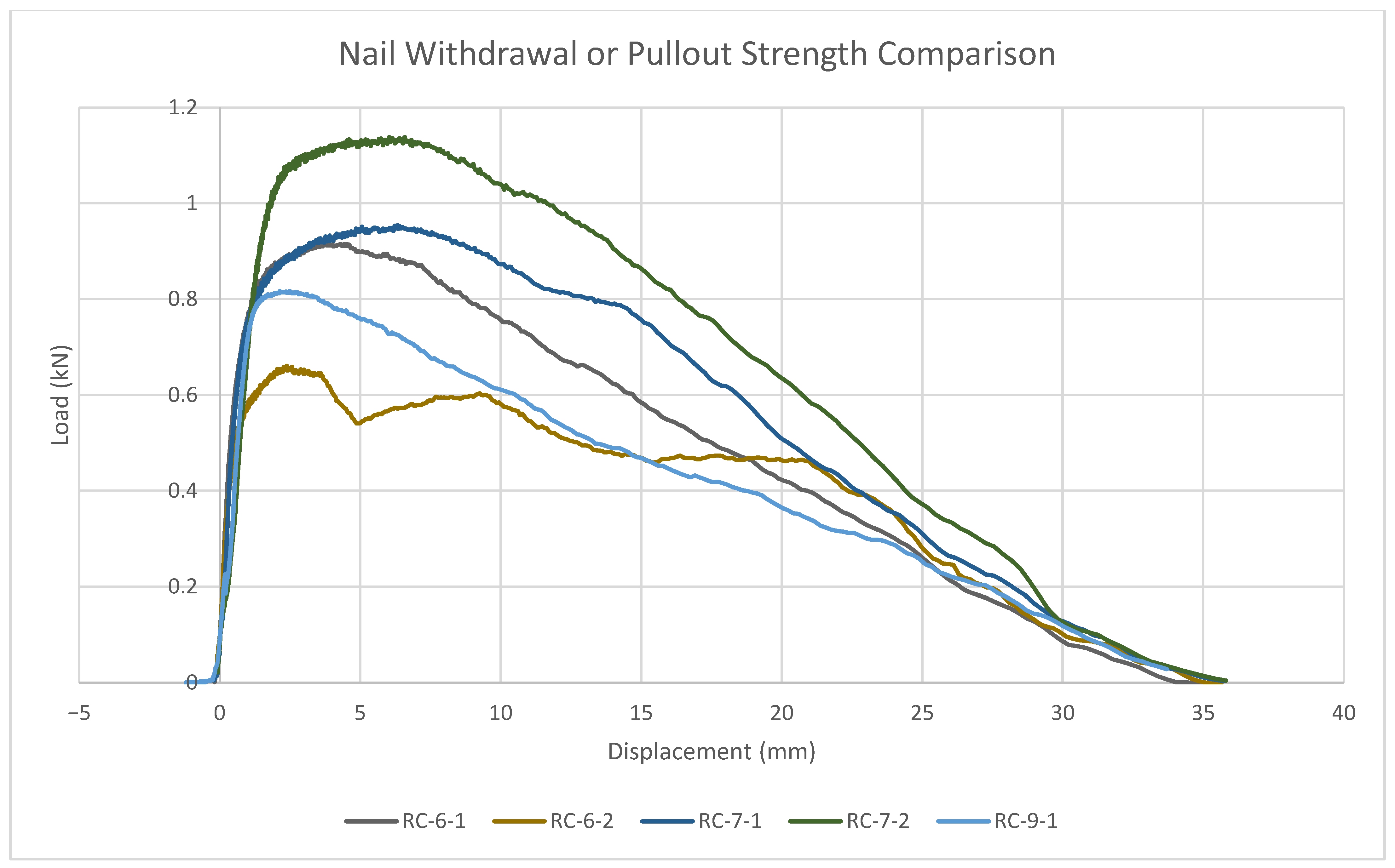
3.4. Pullout or Withdrawal Strength Methods

The nail withdrawal tests were conducted in a method similar to the testing method outlined by ASTM D1037. Due to the presence of available samples with dimensions smaller than the requirements of ASTM D1037, the dimensional requirements could not be met. However, the testing method was representative in that the nails included a standoff and tests were conducted on similarly sized samples of both concrete and wood.
The terminology used in this paper needs to be clarified regarding pullout or withdrawal strength. Throughout this paper, we refer to both terms. This stems from a difference in terminology used in the reinforced concrete and lumber industries. What we are specifically referring to is the ability of a material to resist the extraction of a fastener applied to said material. Within the reinforced concrete industry, the term used is often “pullout” strength, but within the lumber industry, the term used is “withdrawal” strength.
Because the material we are studying bridges a gap between the two industries, we use both terms as this research may be relevant to both groups.
While many fasteners can be used with wood, we tested smooth shank fasteners as these are the most commonly used type of nail. Many building codes allow for the use of smooth shank fasteners in most applications involving structural lumber.
The specific smooth shank fasteners tested were Metabo HPT 2–3/8″ × 0.113″ (60.3 mm length × 2.9 mm diameter) Plastic Strip, Full Round Head, Bright, Non-Coated, Smooth Shank.
The nails were driven using a Metabo Cordless Strip Nailer, though other fastener systems can be used, including pneumatic systems or a hammer. To drive the nail consistently to the same depth, the Metabo Cordless Strip Nailer was set to its minimum driving depth and a 12 mm thick strip of wood was held against the sample to produce the necessary minimum protrusion of approximately 20 mm.

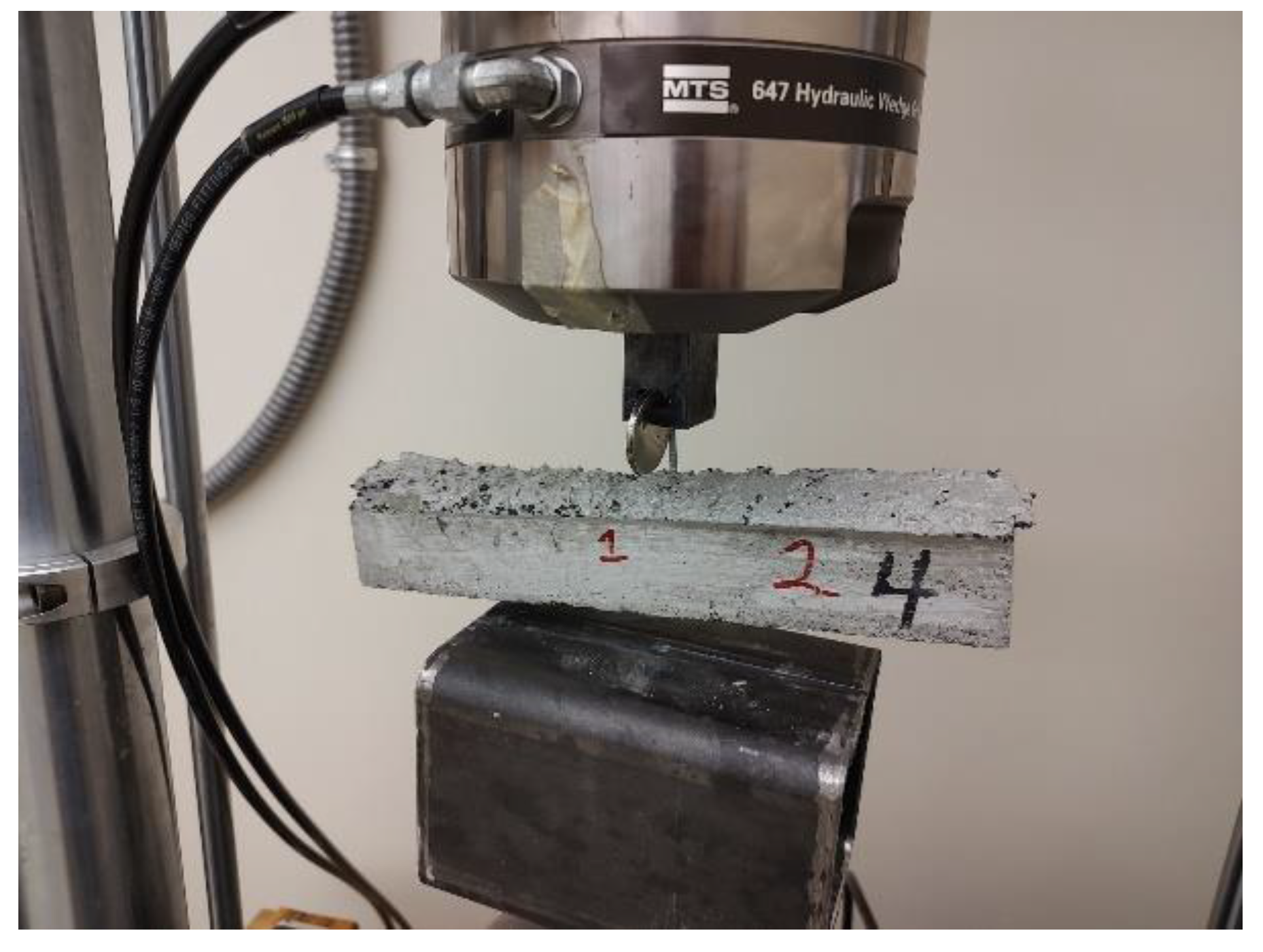
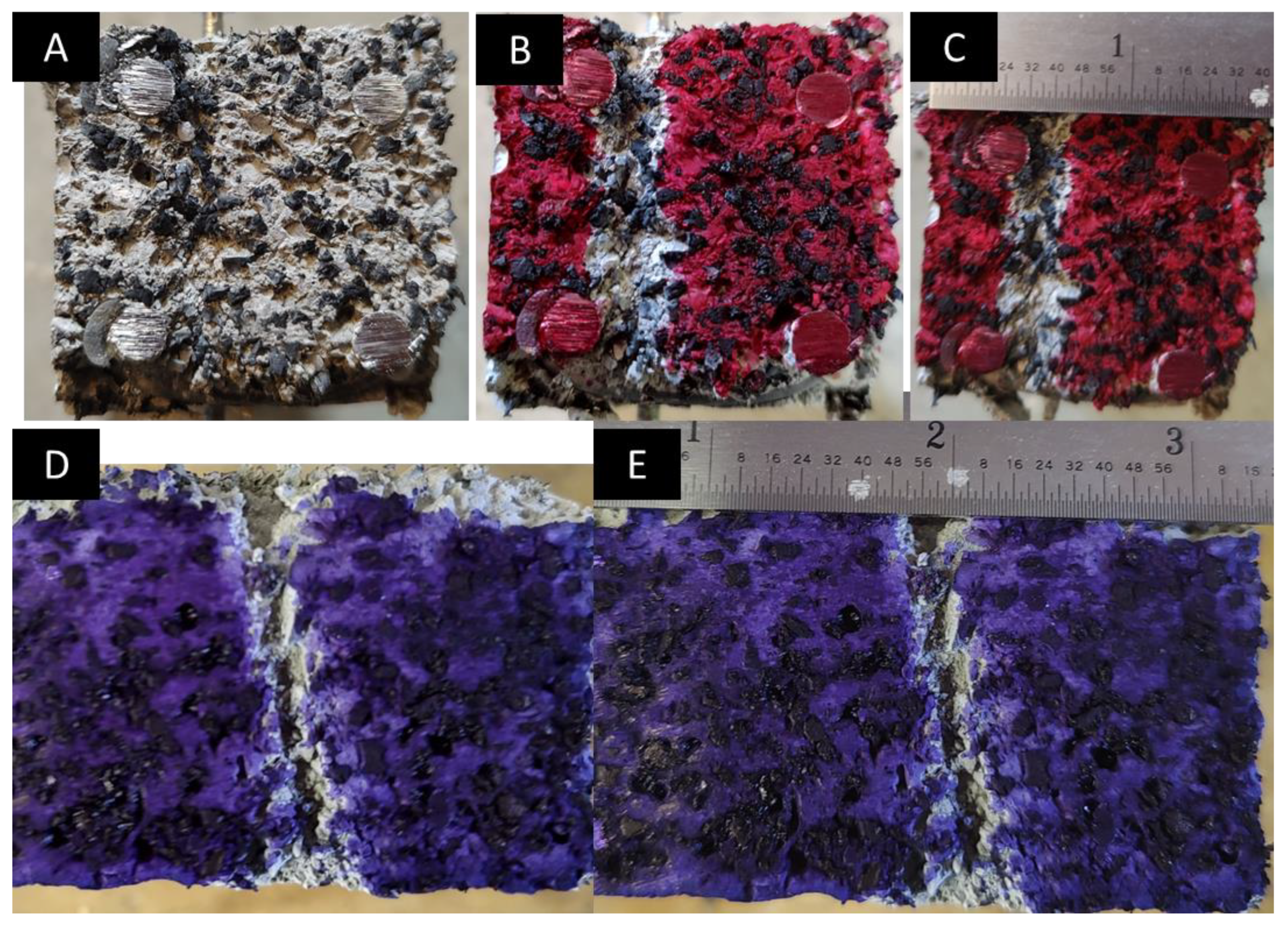
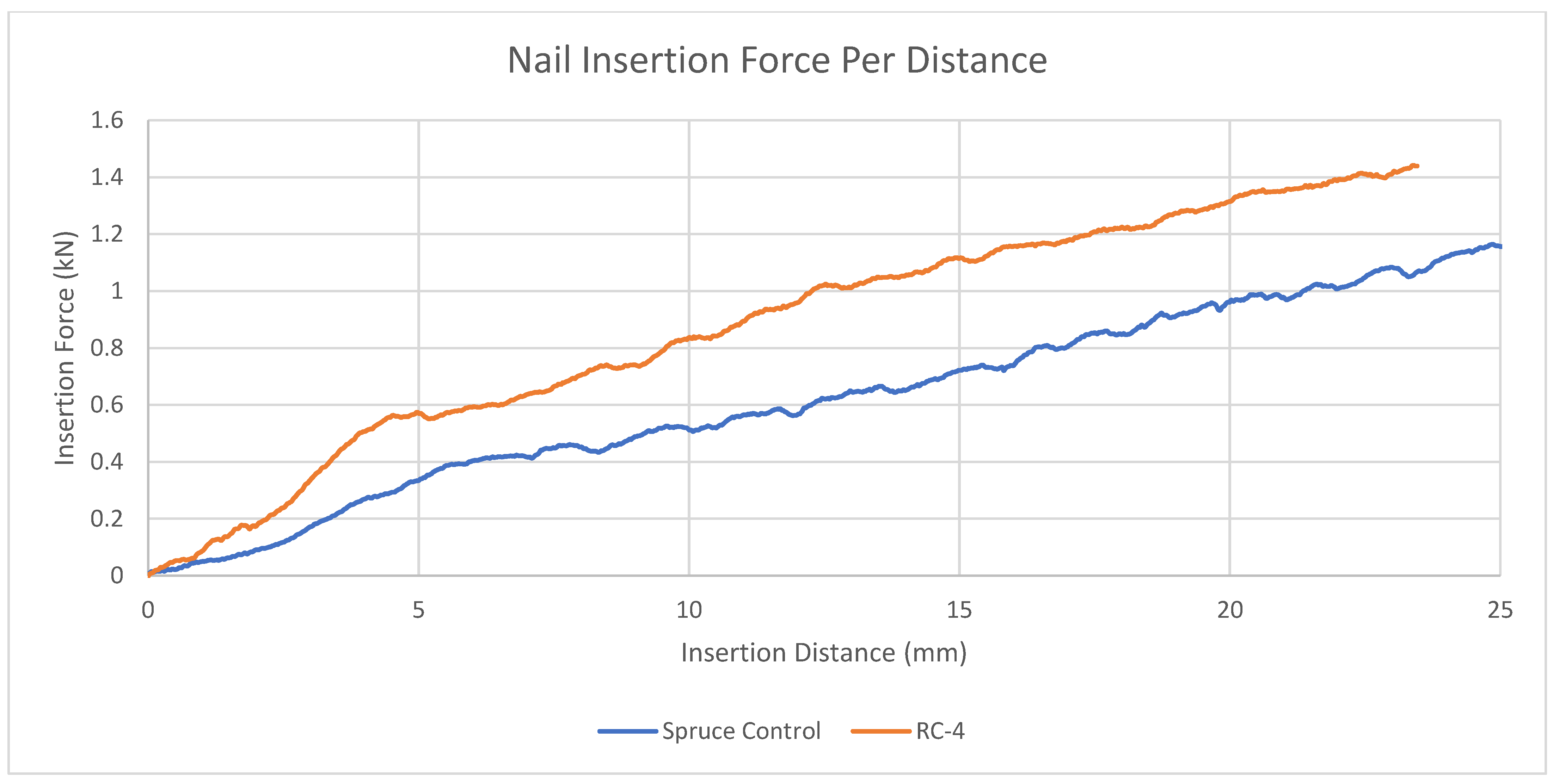
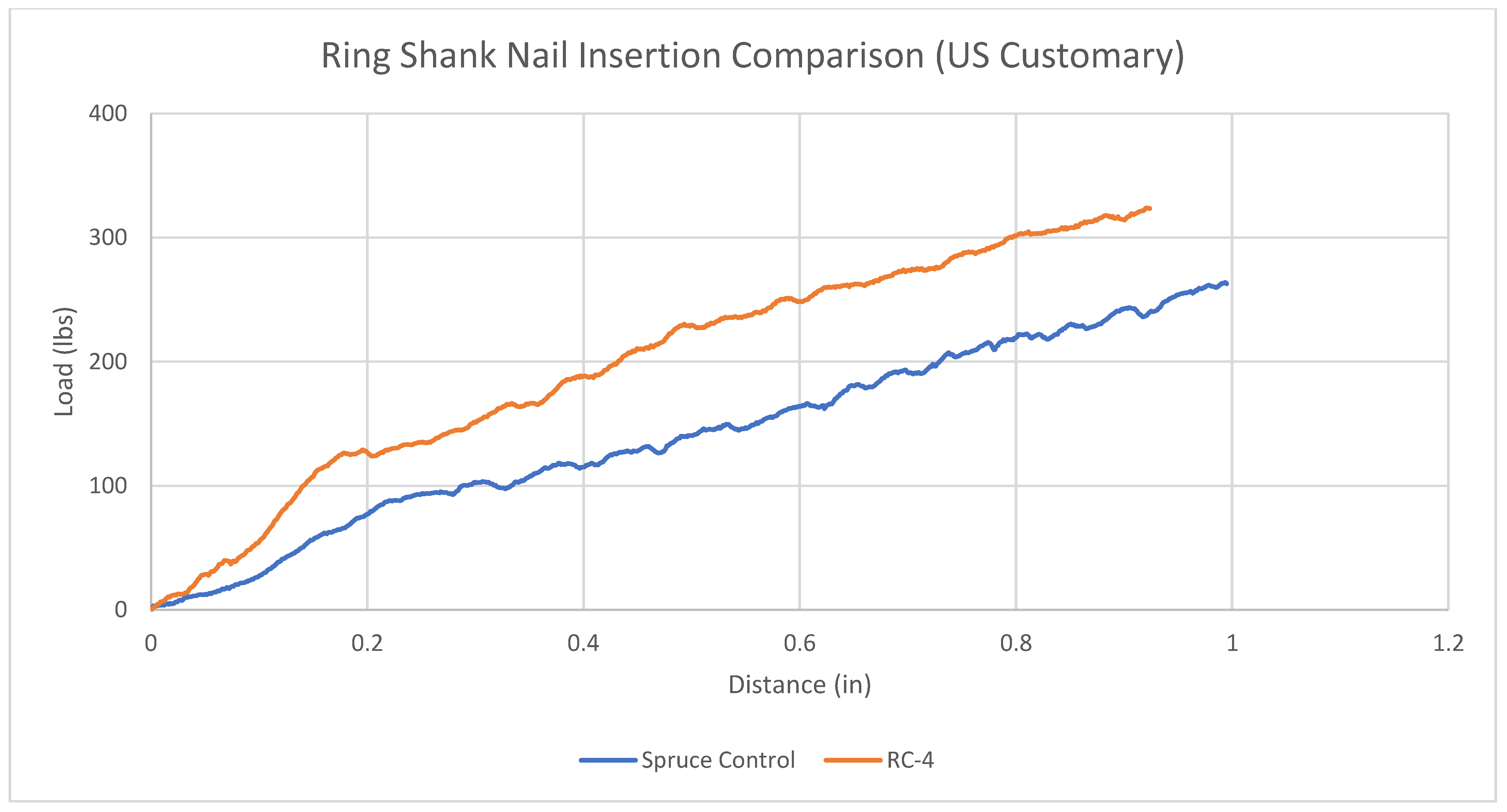
3.5. Nail Insertion Force Tests

Another concern is whether nails can be inserted into a material. This is a key feature of the nailable concrete concept; despite being composed of concrete, the material can be hammered by hand.
To test this concept, MTS 858 was again set up using the nail withdrawal fixture. A disk magnet was attached to the slot to discourage slipping of the nail. The device was run in compression mode to cause the nail to be inserted into the material instead of being withdrawn. The test setup can be seen in Figure 8 below.

4. Results and Analysis

As multiple mechanical properties are investigated simultaneously, it is more appropriate to review the results and analysis for each mechanical property tested separately.

4.1. Bending Moment

4.1.1. Bending Moment Test Results

The bending moment test results are shown in Figure 9 below. Note that there is a US Customary version of this figure in Appendix A, Figure A1. There are multiple points to mention regarding this figure. RC-1 through RC-3 were composed of smooth longitudinal reinforcement and were fixed using hot melt adhesive (HMA). This resulted in poor performance. RC-8 used HMA with threaded longitudinal reinforcement, which greatly improved performance. RC-9 used threaded longitudinal reinforcement and welded connections, which produced the greatest performance when not fully cured. RC-10 performed superiorly when compared to the anticipated allowable loads of the different materials. However, RC-11 and RC-12 suggest that, if the introduction of ridges into longitudinal wire requires threading, it may be more economical to simply use the wire without requiring the additional manufacturing step of threading.
Another interesting note from Figure 9 is that the RC-8, RC-9, and RC-10 beams tend to have a much lower deflection per load when compared to the wood control beams. This is described in more detail in Section 4.1.4.
Bending moment tests were performed iteratively as the results were progressively improved through improved manufacturing methods. As an example, see Figure 10, which shows the RC-3 and RC-8 beams (note that half of the beam was cut and re-used for withdrawal or pullout testing) after failure. RC-3 appeared to have prematurely failed due to the shear reinforcement sliding along the length of the longitudinal reinforcement. These are indicated by the red lines, which show the current location of the nearest shear reinforcement while the red arrow indicates the location of where a shear reinforcement tie was located at the time of manufacture. RC-8, shown in Figure 10B, included a shifting of the tensile longitudinal reinforcement during failure as it pulled away from the end of the beam.
Many ideas were pursued as a fix for the issues shown in Figure 10. These were successfully improved by the introduction of threaded reinforcement, but this alone was insufficient (Figure 10B). By also welding the reinforcement to the threaded rods, significant force was required to shift the reinforcement, as shown in Figure 11 below, even with a short cure time.
However, when looking at the strength comparison of RC-11 and RC-12, the strength of RC-11 was greater than RC-12, despite all conditions being similar except RC-12 having its reinforcement threaded. This means that, given the option of using threaded and smooth reinforcement, it may be superior to simply use smooth reinforcement, as threaded reinforcement will be both weaker and have a higher cost than smooth reinforcement. Threaded reinforcement will inherently have a greater cost as it is the same as the smooth wire but has been further processed by cutting threads. This is a distinction with reinforcement bar typical for concrete, which is deformed to have its shape instead of machined.

4.1.2. Bending Moment Analysis

To better understand how these beams perform, it is necessary to determine the strength of the beams anticipated by calculation. Here, we conservatively assume that the concrete contributes little to the strength and the strength of the beam can be assumed to be nearly that of the reinforcement.
The analysis calculations can be found in Appendix B. In this section, we calculate the estimated bending moment strength of the steel rods by assuming that the concrete only functions to allow the steel the function of a section.
This analysis results in an assumed bending moment strength of 313 kN mm (2700 lbs/in) when assuming 4.8 mm (3/16″) diameter steel rods.
It should be noted here that while the assumption that the concrete contributes little strength may seem overly conservative, in the following section, we indicate that this assumption is appropriate as an approximation.

4.1.3. Safety Factor Considerations

In Figure 9, we can see two obvious differences in the failure type of the RC and the spruce control. As the spruce control fails suddenly, this is suggested to be a brittle failure mode.
Conversely, the RC samples, regardless of the fastening method or the inclusion of threads on reinforcement, have a ductile failure mode due to the obvious strain hardening that occurs during failure.
For the sake of simplicity in explanation, to calculate the allowable loads, standard safety factors of 1.67 for ductile failure and 2.00 for brittle failure were assumed. This is equivalent to assuming, for comparison purposes, a strength reduction factor of 0.9 for ductile and 0.75 for brittle failure of materials when comparing beams.
Considering these factors, the allowable loads for the different samples vary according to what is shown in Table 4 below.
It should be noted that while RC-11 was threaded, and should therefore perform to a higher load, it performed more poorly when compared to RC-12. This means, however, that while the concrete theoretically performs superiorly when using a grooved longitudinal reinforcement, it may be preferential to incorporate a larger diameter rod due to the increased surface area.
Additionally, considering the results indicated in Table 4, the maximum bending moment calculated using the assumption that the concrete attributes little strength resulted in a bending moment strength of 313 kN mm. Looking at the table, this value is nearly the value of RC-9. This is appropriate as the concrete mix in RC-9 had insufficient time to cure, meaning that the concrete does contribute little to the strength of the section. Additionally, RC-9 uses a larger 6.4 mm threaded rod. However, a 6.4 mm threaded rod has a nearly 4.8 mm diameter at the unthreaded section as threaded rod diameters are referenced from the outside of the threaded rod.
Additionally, RC-10 has a greater maximum bending moment strength, meaning that the concrete does supply some strength in these sections. However, RC-11, which has sufficient concrete curing and unthreaded, 4.8 mm diameter rods, results in a lower bending moment strength. We assume that this reduction is due to the sliding of the reinforcement relative to the concrete.

4.1.4. Serviceability Considerations

As has been mentioned in previous sections, deflection or serviceability requirements often dictate design of structures, in particular wood structures. This is a function of the relative stiffness (resistance to deflection) with respect to the strength of the material.
Accordingly, the deflection of the different beams tested are compared in Table 5 below. This table includes columns that indicate that the deflection of the beams both at the equivalent wood-allowable load anticipated for the design and the individual allowable load for each beam. In general, the reinforced concrete beams have a greater resistance to deflection, due primarily to the inclusion of steel reinforcement.
RC-10 is the beam with the greatest bending moment strength. This beam resulted in a deflection that was 41% less than the wood equivalent. This suggests that certain designs using the concrete may actually allow for fewer concrete beams for a given structure, but this is highly dependent on the specific design. For example, the most lenient deflection criteria in the 2015 IBC (1604.3 Serviceability, Table 1604.3 Deflection Limits, ref. [35]) is L/120, which means all of the tested beams would be required to be loaded far below the allowable load.

4.2. Pullout or Withdrawal Strength

Prior to reviewing the test results, it is necessary to indicate the testing parameters from which the tests were conducted. These testing parameters are included in Table 6 below. Note that for any beam indicated here that is also included in Table 4, the bending moment tests occurred first. This means that the beams were tested after bending moment failure by cutting an intact section of the failed beam and nailing into that section.

4.2.1. Pullout or Withdrawal Strength Test Results

As previously mentioned, nail withdrawal was tested using smooth shank nails. The tests conducted are shown in Figure 12 below. There is a US Customary version of Figure 12 located in Appendix A, Figure A2. Note that in this figure, all the tests were aligned at approximately 0.08 kN. The misalignment resulted from the testing apparatus being misaligned at the onset of some tests.
When reviewing the beam properties (Table 2, page 8), it can be seen that RC-7, the beam with the greatest withdrawal (or pullout) strength, is a simplistic design, but it was not previously tested to bending moment failure. It is assumed that there is some degree of variability in withdrawal (or pullout) strength due to variability inherent to the insertion method of the fasteners (e.g., misalignment when nailing, nails striking a wire, etc.) or otherwise caused by testing the beam to bending moment failure beforehand.
As the graphs included in Figure 12 are difficult to interpret, Figure A3, Figure A4, Figure A5, Figure A6, Figure A7 and Figure A8 in the appendix contain subsets of each set of readings in both Metric and US Customary units.

4.2.2. Pullout or Withdrawal Analysis

To understand how the RC is performing, cavities were cut in the concrete from different tests. Examples of this can be seen in Figure 13 below. In these figures, two test results are shown for the smooth shank nail.
An analysis was performed to estimate the shear strength of the concrete at the interface. The interface was approximated as a simple cylinder with a diameter of 3.2 mm and a length of 41.3 mm. The load assumed was the maximum withdrawal load of 1.14 kN for the RC-7-2 test. The analysis is shown in Appendix B, Equations (A9) through (A12). The result of this analysis is that the shear strength of the concrete mix is approximately 2.77 MPa (401 psi).
Table 7 below is a summary of the test results for the nail withdrawal tests, which includes the shear stress analysis as well as the withdrawal load measured based on the embedment length.
Note that it is assumed that other fasteners likely have a similar failure stress as those expressed here, but the failure surface assumed may have a larger or smaller diameter than shown.

4.3. Nail Insertion Force Results and Analysis

It is necessary to test nail insertion to fulfill the concept or criteria of “nailability;” that is, we need to prove that this material could be nailed together as though it were wood and can be accomplished by hand.
The nail insertion force is shown in Figure 14 below. This figure is recreated in US Customary units in Appendix A, Figure A9. In this figure, the forces necessary to push a nail slowly into the concrete and the spruce sample (for comparison) are shown per distance. As the nail drives further into the materials, the frictional force increases. It should be noted that this is not directly comparable to driving a nail conventionally, as the loading speed here is over the course of 120 s.
The region of Figure 14 from 0 to 5 mm is important. The concrete sample is shown to have a greater rate of insertion force increase here. While this increase seems arbitrary, this is likely caused by a region of high Portland cement content and lower rubber inclusion. The material seems to automatically form a harder shell of Portland cement during casting. This may make setting nails difficult with this specific mixture (a negative, particularly if hammering by hand) but may lead to an automatically forming protective coating that may reduce wear at the cast surfaces of this concrete (a potential positive in many applications). This is somewhat speculative and should be investigated more thoroughly.
Table 8 is a brief summary of the results shown in Figure 14.
While this value of insertion force seems excessive, as there is a harder surface on the RC samples, it is likely that the nail insertion force maintains a consistent 0.35 kN increase; this means that as a nail is driven further, the percentage difference in insertion force decreases as the shell of stronger Portland cement becomes less significant. For example, if driven to a depth of 75 mm, the concrete would only require a 9.5% increase in driving force.

5. Discussion

As mentioned previously, this concrete mix, despite having less strength than traditional concretes, still provides key properties that allow it, when reinforced with steel wire, to provide a material with a similar strength to that of treated lumber in several key parameters. A summary of the bending moment tests is provided in Table 9 below, which highlights the best test results for the best design of the reinforcement.
Table 10 below is a summary of the withdrawal tests, comparing the averages and the maximum withdrawal strengths of the smooth shank nails tested. While the spruce control beam had a greater withdrawal strength average, the maximum withdrawal strength of the concrete was much higher. This could result from two possibilities: (1) the concrete mix has an inherently greater standard deviation that cannot be substantially improved, or (2) the concrete manufacturing process or the mix can be improved to attain the indicated maximum withdrawal strength more consistently.
The specific cause of the withdrawal strength difference for the concrete mixes between the average and maximum may be inconsequential in practical application. The slight difference in withdrawal strength can easily be overcome with an additional nail installed or the use of longer nails. The time required to install an additional nail or drive in a longer one is insignificant when comparing it to the installation speed of fasteners into traditional concrete mixtures.

Limitations

Limitations can occur in many ways within a study. Our notable limitations include the following aspects:
  • The samples tested are of reduced dimensions due to size limitations of the available testing apparatus.
  • Due to size limitations, reduced sample sizes were tested. This prevented us from following ASTM D1037. To avoid bias in the results, we tested both the wood control specimens and nailable rubber concrete with the same methods.
  • Compressive strength tests were not included. Due to the high rubber infill, this concrete begins to behave more like a foam. This results in a difficult-to-define compressive strength when comparing it directly to that of a typical concrete, as it is unknown whether it is preferential to indicate the compressive strength before or after densification as the rubber particles are crushed within the concrete.

6. Conclusions

The research presented here regarding a novel mix of rubber concrete that allows the concrete transformation into “nailable” provides the following conclusions:
  • Rubber concretes, when mixed in the correct proportions, can be developed to have withdrawal strengths similar to those of typical wood species used in construction. This allows withdrawal strengths of up to 25% greater than those of comparable wood samples.
  • The resulting nailable rubber concrete can be reinforced to remain economical while providing up to a 13% greater allowable load.
  • The nailable rubber concrete can also be manufactured economically to allow for a 41% reduction in deflection. This is a significant improvement, as one of the common issues in engineering design is minimizing deflection as opposed to strictly maximizing strength.
  • The nailable rubber concrete mix researched here requires only a slight increase in driving force, compared to the wood samples tested, in practical application. For example, driving to a depth of 75 mm requires only a 9.5% increase in driving force.
  • These benefits of the researched nailable rubber concrete can be attained while both providing an alternative to arsenic-bearing treated wood and a cost-effective use for recycled rubber tires.
  • This nailable rubber concrete is a reinforced concrete that is anticipated to last five times longer than treated wood alternatives within the Southeastern United States, as this concrete does not suffer from environmental degradation due to fungi, insects, etc. This further strengthens the economic argument regarding use of this material as a treated wood alternative.
Accordingly, we conclude that this nailable rubber concrete may be a superior alternative to treated lumber, especially when considering the environmental and economic benefits. We recommend this nailable rubber concrete for construction professionals and policymakers.

Future Work

The future aim for work in regard to this technology is to determine superior concrete mixes. As we only tested a single mix, though we have proven that this concept of a nailable rubber concrete is possible, future work will likely yield superior mixes that maximize the withdrawal strength while considering economical design.

7. Patents

A nonprovisional patent was filed on 14 March 2023 for the invention included in this research paper, with the current patent number US Patent Application No. 18/183,271, as the application has not been granted yet.

Author Contributions

Conceptualization, J.C.; methodology, J.C.; formal analysis, J.C.; investigation, J.C.; resources, J.C.; writing—original draft preparation, J.C.; writing—review and editing, R.G.; project administration, J.C. All authors have read and agreed to the published version of the manuscript.

Funding

This research received no external funding.

Data Availability Statement

The data presented in this study are available on request from the corresponding author. The data are not publicly available due to additional patent filings.

Conflicts of Interest

The University of South Florida applied for a nonprovisional patent with the United States Patent and Trademark Office regarding the glass reinforced composite column technology.

Appendix A

Appendix A includes additional figures recreated in US Customary units.
Figure A1. Figure 9 is recreated in US Customary units. These are the 3-point bending test results comparing the spruce control beam against the nailable rubber concrete beams of various designs. See Table 2 for information regarding the specific properties of each section.
Jcs 07 00405 g0a1
Figure A2. Figure 12 is recreated in US Customary units. This is the force developed as the nails are pulled from the various samples.
Jcs 07 00405 g0a2
Figure A3. Figure 12 is reduced to the samples shown, for clarification, and in Metric units.
Jcs 07 00405 g0a3
Figure A4. Figure 12 is reduced to the samples shown, for clarification, and in US Customary units.
Jcs 07 00405 g0a4
Figure A5. Figure 12 is reduced to the samples shown, for clarification, and in Metric units.
Jcs 07 00405 g0a5
Figure A6. Figure 12 is reduced to the samples shown, for clarification, and in US Customary.
Jcs 07 00405 g0a6
Figure A7. Figure 12 is reduced to the samples shown, for clarification, and in Metric units. Note that these are the control beams.
Jcs 07 00405 g0a7
Figure A8. Figure 12 is reduced to the samples shown, for clarification, and in US Customary units. Note that these are the control beams.
Jcs 07 00405 g0a8
Figure A9. Figure 13 is recreated in US Customary units. This is the force required to insert a nail into the different materials shown. Note the steeper incline for the RC sample from 0 to 0.2 inches.
Jcs 07 00405 g0a9

Appendix B

In Appendix B, we perform calculations to determine the strength of the steel associated with the tested concrete beams, assuming that the concrete provides little to no strength. (A1)–(A4) estimate the bending moment strength using SI units while (A5)–(A8) use US Customary units.
A r o d = π 4 d r o d 2 = π 4 ( 4.8   m m ) 2 = 18.1   m m 2 ,
d = h 2 · c o v e r = 41.3   m m 2 3.2   m m = 34.9   m m ,
I = n A r o d y 2 = n A r o d d 2 2 = 4 18.1   m m 2 34.9   m m 2 2 = 22,046   m m 4 ,
σ I C = M = ( 248   M P a ) 22,046   m m 4 34.9   m m 2 = 313   k N · m m ,
where Arod is the area of the longitudinal rods, individually, drod is the diameter of the longitudinal rods, d is the effective depth of the reinforcement of the section, h is the total depth of the beam, cover is the concrete cover thickness, I is the second geometric moment, y is the distance from the reinforcement to the neutral axis, c is the distance from the neutral axis to the reinforcement (which is the same as y in this example), M is the bending moment at the considered stress, and σ is the stress considered, which is the yield stress of the steel in this example.
The process is repeated using US Customary units:
A r o d = π 4 d r o d 2 = π 4 ( 0.1875 i n ) 2 = 0.028   i n 2 ,
d = h 2 · c o v e r = 1.625   i n 2 0.125   i n = 1.375   i n ,
I = n A r o d y 2 = n A r o d ( d 2 ) 2 = ( 4 ) ( 0.028   i n 2 ) 1.375   i n 2 2 = 0.052   i n 4 ,
σ I C = M = ( 36000   p s i ) ( 0.052   i n 4 ) 1.375   i n 2 = 2732   l b s · i n .
The following analysis is performed to estimate the shear strength of the concrete at the nail withdrawal (or pullout) interface. The interface is approximated as a simple cylinder with a diameter of 3.2 mm and a length of 41.3 mm. The load assumed is the maximum withdrawal load of 1.14 kN for the RC-7-2 test. The analysis is shown in Appendix B, Equations (A9) through (A12). The result of this analysis is that the shear strength of the concrete mix is approximately 2.77 MPa (401 psi):
S A c a v i t y = π d c a v i t y h e m b e d m e n t ,
τ w i t h d r a w a l ,   f a i l u r e = F w i t h d r a w a l ,   f a i l u r e S A c a v i t y ,
τ w i t h d r a w a l ,   f a i l u r e = F w i t h d r a w a l ,   f a i l u r e π d c a v i t y h e m b e d m e n t ,
τ w i t h d r a w a l ,   f a i l u r e = 1.14   k N π 3.2   m m 41.3   m m = 2.77   M P a ,
τ w i t h d r a w a l ,   f a i l u r e = 256   l b s π 0.125 1.625 = 401   p s i ,
where SAcavity is the surface area inside the section of the material after the nail is removed; dcavity is the diameter of the cavity created by the nail being extracted; hembedment is the depth of the hole inside the material; τwithdrawal,failure is the failure shear of the interface; and Fwithdrawal,failure is the failure load.

References

  1. Walsh-Korb, Z.; Avérous, L. Recent developments in the conservation of materials properties of historical wood. Prog. Mater. Sci. 2019, 102, 167–221. [Google Scholar] [CrossRef]
  2. Florian, M.-L.E. Scope and History of Archaeological Wood; ACS Publications; Royal British Columbia Museum: Victoria, BC, Canada, 1990. [Google Scholar]
  3. Ramage, M.H.; Burridge, H.; Busse-Wicher, M.; Fereday, G.; Reynolds, T.; Shah, D.U.; Wu, G.; Yu, L.; Fleming, P.; Densley-Tingley, D. The wood from the trees: The use of timber in construction. Renew. Sustain. Energy Rev. 2017, 68, 333–359. [Google Scholar] [CrossRef]
  4. Wimmers, G. Wood: A construction material for tall buildings. Nat. Rev. Mater. 2017, 2, 17051. [Google Scholar] [CrossRef]
  5. Nicholas, D.D. Wood Deterioration and Its Prevention by Preservative Treatments: Volume 1: Degradation and Protection of Wood; Syracuse University Press: Syracuse, NY, USA, 1973. [Google Scholar]
  6. Schultz, T.P.; Nicholas, D.D.; Preston, A.F. A brief review of the past, present and future of wood preservation. Pest Manag. Sci. Former. Pestic. Sci. 2007, 63, 784–788. [Google Scholar] [CrossRef]
  7. Morais, S.; Fonseca, H.M.; Oliveira, S.M.; Oliveira, H.; Gupta, V.K.; Sharma, B.; de Lourdes Pereira, M. Environmental and health hazards of chromated copper arsenate-treated wood: A review. Int. J. Environ. Res. Public Health 2021, 18, 5518. [Google Scholar] [CrossRef] [PubMed]
  8. Altaner, C. Preservative Treated Timber Products in New Zealand. Cellul. Chem. Technol. 2022, 56, 705–716. [Google Scholar] [CrossRef]
  9. Tsang, M.P.; Bates, M.E.; Madison, M.; Linkov, I. Benefits and risks of emerging technologies: Integrating life cycle assessment and decision analysis to assess lumber treatment alternatives. Environ. Sci. Technol. 2014, 48, 11543–11550. [Google Scholar] [CrossRef]
  10. Tsang, M.; Meyer, D.; Hawkins, T.; Ingwersen, W.; Sayre, P. Life cycle assessment for emerging materials: Case study of a garden bed constructed from lumber produced with three different copper treatments. Int. J. Life Cycle Assess. 2014, 19, 1345–1355. [Google Scholar] [CrossRef]
  11. Katz, S.A.; Salem, H. Chemistry and toxicology of building timbers pressure-treated with chromated copper arsenate: A review. J. Appl. Toxicol. Int. J. 2005, 25, 1–7. [Google Scholar] [CrossRef]
  12. Bolin, C.A.; Smith, S. Life cycle assessment of ACQ-treated lumber with comparison to wood plastic composite decking. J. Clean. Prod. 2011, 19, 620–629. [Google Scholar] [CrossRef]
  13. Saxe, J.K.; Wannamaker, E.J.; Conklin, S.W.; Shupe, T.F.; Beck, B.D. Evaluating landfill disposal of chromated copper arsenate (CCA) treated wood and potential effects on groundwater: Evidence from Florida. Chemosphere 2007, 66, 496–504. [Google Scholar] [CrossRef] [PubMed]
  14. Cooper, P.A. Disposal of treated wood removed from service: The issues. In Proceedings of the Environmental Considerations in the Use of Pressure-Treated Wood Products” Carolinas-Chesapeake Section of the Forest Products Society: Richmond, Richmond, VA, USA, 13 May 1993. [Google Scholar]
  15. McQueen, J.; Stevens, J. Disposal of CCA-treated wood. For. Prod. J. 1998, 48, 86. [Google Scholar]
  16. Alderman Jr, D.; Smith, R.; Araman, P. A profile of CCA-treated lumber removed from service in the southeastern United States decking market. For. Prod. J. 2003, 53, 38. [Google Scholar]
  17. Bertolini, L. Steel corrosion and service life of reinforced concrete structures. Struct. Infrastruct. Eng. 2008, 4, 123–137. [Google Scholar] [CrossRef]
  18. Chauhan, M.; Sood, H. Rubber Modified Concrete-A Green Approach For Sustainable Infrastructural Development. Int. Res. J. Eng. Technol. (IRJET) 2017, 4, 973–978. [Google Scholar]
  19. Siddika, A.; Al Mamun, M.A.; Alyousef, R.; Amran, Y.M.; Aslani, F.; Alabduljabbar, H. Properties and utilizations of waste tire rubber in concrete: A review. Constr. Build. Mater. 2019, 224, 711–731. [Google Scholar] [CrossRef]
  20. Fang, Y.; Zhan, M.; Wang, Y. The status of recycling of waste rubber. Mater. Des. 2001, 22, 123–128. [Google Scholar] [CrossRef]
  21. Roychand, R.; Gravina, R.J.; Zhuge, Y.; Ma, X.; Youssf, O.; Mills, J.E. A comprehensive review on the mechanical properties of waste tire rubber concrete. Constr. Build. Mater. 2020, 237, 117651. [Google Scholar] [CrossRef]
  22. Ahmad, J.; Zhou, Z.; Majdi, A.; Alqurashi, M.; Deifalla, A.F. Overview of Concrete Performance Made with Waste Rubber Tires: A Step toward Sustainable Concrete. Materials 2022, 15, 5518. [Google Scholar] [CrossRef]
  23. Akbar, M.; Hussain, Z.; Huali, P.; Imran, M.; Thomas, B.S. Impact of waste crumb rubber on concrete performance incorporating silica fume and fly ash to make a sustainable low carbon concrete. Struct. Eng. Mech. 2023, 85, 275–287. [Google Scholar]
  24. Jin, D.; Boateng, K.A.; Ge, D.; Che, T.; Yin, L.; Harrall, W.; You, Z. A case study of the comparison between rubberized and polymer modified asphalt on heavy traffic pavement in wet and freeze environment. Case Stud. Constr. Mater. 2023, 18, e01847. [Google Scholar] [CrossRef]
  25. Jin, D.; Ge, D.; Wang, J.; Malburg, L.; You, Z. Reconstruction of Asphalt Pavements with Crumb Rubber Modified Asphalt Mixture in Cold Region: Material Characterization, Construction, and Performance. Materials 2023, 16, 1874. [Google Scholar] [CrossRef]
  26. Jin, D.; Boateng, K.A.; Chen, S.; Xin, K.; You, Z. Comparison of Rubber Asphalt with Polymer Asphalt under Long-Term Aging Conditions in Michigan. Sustainability 2022, 14, 10987. [Google Scholar] [CrossRef]
  27. Lyle, C. Nailable Concrete. U.S. Patent U.S. Patent No. 2,542,992, 27 February 1951. [Google Scholar]
  28. The Aberdeen Group. Waste Materials in Concrete. Concrete Construction. Publication# C710372. 1971. Available online: https://www.concreteconstruction.net/how-to/materials/waste-materials-in-concrete_o (accessed on 2 September 2023).
  29. Siddique, R.; Naik, T.R. Properties of concrete containing scrap-tire rubber—An overview. Waste Manag. 2004, 24, 563–569. [Google Scholar] [CrossRef]
  30. Aliabdo, A.A.; Abd Elmoaty, M.; AbdElbaset, M.M. Utilization of waste rubber in non-structural applications. Constr. Build. Mater. 2015, 91, 195–207. [Google Scholar] [CrossRef]
  31. Topcu, I.B. The properties of rubberized concretes. Cem. Concr. Res. 1995, 25, 304–310. [Google Scholar] [CrossRef]
  32. Eldin, N.N.; Senouci, A.B. Rubber-tire particles as concrete aggregate. J. Mater. Civ. Eng. 1993, 5, 478–496. [Google Scholar] [CrossRef]
  33. Wang, Y.; Lee, S.-H. A theoretical model developed for predicting nail withdrawal load from wood by mechanics. Eur. J. Wood Wood Prod. 2018, 76, 973–978. [Google Scholar] [CrossRef]
  34. Stewart, J.; Moore, J. Chemical techniques of historic mortar analysis. Bull. Assoc. Preserv. Technol. 1982, 14, 11–16. [Google Scholar] [CrossRef]
  35. Code, U.B. International Building Code. Chapter 16 Structural Design. 1604.3 Serviceability, International Code Council, USA. 2015. Available online: https://codes.iccsafe.org/s/IBC2015/chapter-16-structural-design/IBC2015-Ch16-Sec1604.3 (accessed on 2 September 2023).
Figure 1. An example beam cross-section showing the recycled crumb rubber infill proportion. The high volumetric ratio of the crumb rubber can be seen.
Jcs 07 00405 g001
Figure 2. The method of bending small wire ties for the shear reinforcement for the test concrete beams.
Jcs 07 00405 g002
Figure 3. (A) An example of a wire cage manufactured with HMA as the fixture. (B) An example of a welded wire reinforcement cage after removal from the manufacturing jig. (CF) The red arrows indicate the progression of steps of placing the shear reinforcement, sliding it into place, connecting the grounding wire for welding, and welding the shear reinforcement into place.
Jcs 07 00405 g003
Figure 4. Beams RC-1 through RC-5 are shown before casting. Reinforcement cages, which are attached using hot melt adhesive, are shown out of the formwork as well as inside the formwork. The cages are approximately 248 mm (9.75 inches) long and the individual test beams after casting are 254 mm (10 inches) in length.
Jcs 07 00405 g004
Figure 5. Beams RC-6 through RC-9 are shown before casting. Beam RC-9, the only beam tested with welded fixture of the shear reinforcement, is the most significant sample tested to date.
Jcs 07 00405 g005
Figure 6. Details showing the dimensions of the withdrawal testing apparatus as well as a general arrangement detailing how the device fits within the hydraulic clamping wedges of the device.
Jcs 07 00405 g006
Figure 7. (A,B) The lower section of the nail withdrawal tester is shown. (C) The 3 mm (0.125″) nail withdrawal tester is shown with a nail in the holder while a sample is within the hollow structural steel. (D) The withdrawal testing device is shown with a sample inside. The sample is currently being suspended by the nail protruding into the pulling device above the hollow section below.
Jcs 07 00405 g007
Figure 8. The nail withdrawal or pullout test setup is run in reverse to measure the force required to insert a nail into the rubber concrete and the wood. The red numbers shown indicate testing locations while the black number 4 indicates RC-4.
Jcs 07 00405 g008
Figure 9. The RC-10 beam is tested and shown in comparison to the others. Note the substantial increase in strength. Note that this is for a simply supported beam loaded at its middle point with a 152 mm (6-inch) span. See Appendix A, Figure A1 for a US Customary version of this figure.
Jcs 07 00405 g009
Figure 10. Examples from two failed beams. (A) RC-3 is shown with the shear reinforcement dislocated from its original position, having shifted along the length of the longitudinal reinforcement due to improper attachment. The arrow is pointing to a location where the lower part of a shear reinforcement tie is supposed to be located. (B) The RC-8 beam is shown with the longitudinal reinforcement shifted forward, as indicated by the red arrows and lines.
Jcs 07 00405 g010
Figure 11. The failed RC-9 beam is shown.
Jcs 07 00405 g011
Figure 12. The smooth shank tests are shown for all samples with the data shifted for alignment. See Appendix A, Figure A2 for a US Customary version of this figure.
Jcs 07 00405 g012
Figure 13. The cavities from two smooth shank nail tests are shown in (A) through (E). In (B,C), a red dye was applied while a blue dye was used in (D,E). The dye helps to highlight the region from which the nail had to be pulled through to remove it from the concrete. It is assumed that the rubber at these interfaces works to increase the frictional force required to extract the nail. Note that the ruler shown is in US Customary units, but the cavity shown in both images is approximately 3.2 mm (0.125″).
Jcs 07 00405 g013
Figure 14. The nail insertion tests for the wood control beams and RC-4. Note the region from 0 to 5 mm in which the RC-4 beam has a greater rate of increase in insertion force. See Appendix A, Figure A3 for a US Customary version of this figure.
Jcs 07 00405 g014
Table 1. The concrete mixture used, shown as masses used to make the mixture.
Weight (kgs)
SandPortland CementCrumb RubberSum (kgs)
10.034.312.456.7
Table 2. The properties of each sample used for testing for the bending moment strength. Note that some beams may have been used for bending moment, withdrawal testing (see RC-6 and RC-7), or both. Note that all tested beams included a 2.0 mm (0.08 in) shear reinforcement wire diameter.
RC SampleCuring Time (Days)Attachment MethodLongitudinal Diameter, mm (in)Additional Notes
RC-15HMA4.8 (3/16)
RC-212HMA4.8 (3/16)
RC-328HMA4.8 (3/16)Sand blasted longitudinal reinforcement
RC-428HMA4.8 (3/16)(4) Extra longitudinal reinforcement, used only for withdrawal tests
RC-528HMA4.8 (3/16)(4) Extra longitudinal reinforcement, used only for withdrawal tests
RC-6N/AHMA4.8 (3/16)Used only for withdrawal tests
RC-7N/AHMA6.4 (1/4)Used only for withdrawal tests
RC-84HMA6.4 (1/4)Threaded longitudinal
RC-94Welded6.4 (1/4)Threaded longitudinal
RC-10>28Welded6.4 (1/4)Threaded longitudinal
RC-11>28Welded4.8 (3/16)
RC-12>28Welded4.8 (3/16)Threaded longitudinal
Table 3. The components utilized alongside the MTS 858 machine. The only additional component used is the apparatus detailed in Figure 6 and Figure 7 that was utilized for withdrawal testing.
ItemModelAdditional Information
Stroke Actuator359-XXMTS 3000 PSI 3.3 KIP 4″ Stroke Actuator
Wedge Set647.01BFlat/Serrated-Sawtooth 0.74–1.02 inch (18.9–25.9 mm)
Load Cell661.19F-0425 kN Maximum Load, Force Transducer Load Cell
Bend Fixture642.01A3-Point Bending Moment Fixture, 30 kN (6700 lbf) Force Limit
Table 4. The maximum and allowable loads are shown, as measured by the MTS 858 system using a 3-point bending fixture with a spacing of 152.4 mm (6″). The maximum and allowable bending moments are calculated. Values are shown in SI and US Customary units (in brackets). Bold indicates the best test case and wood control specimen values for easier comparison.
SampleMaximum Load, kN (lbs)Allowable Load, kN (lbs)Maximum Bending Moment, kN-mm (lbs/in)Allowable Bending Moment, kN-mm (lbs/in)
RC-13.16 (711)1.89 (426)121 (1067)72 (639)
RC-24.80 (1079)2.87 (646)183 (1618)109 (969)
RC-34.13 (928)2.47 (555)157 (1391)94 (833)
RC-86.46 (1453)3.87 (870)246 (2180)147 (1305)
RC-98.10 (1822)4.85 (1091)309 (2732)185 (1636)
RC-108.60 (1934)5.15 (1158)328 (2901)196 (1737)
RC-117.14 (1604)4.27 (961)272 (2406)163 (1441)
RC-125.53 (1243)3.31 (744)211 (1864)126 (1116)
Spruce Control9.15 (2057)4.57 (1029)349 (3086)174 (1543)
Table 5. The allowable loads are shown for reference. The deflections are shown assuming the allowable wood beam control allowable load as well as the best possible for each beam. Bold indicates the best test condition for the rubber concrete and the values for the wood control beam. SI units are shown alongside US Customary units (in brackets).
SampleAllowable Load, kN (lbs)Deflection at Allowable Load 4.57 kNDeflection at Allowable for Each Beam
mm (in)Lmm (in)L
RC-11.89 (426)N/AN/A2.05 (0.081)L/74
RC-22.87 (646)N/AN/A2.54 (0.100)L/60
RC-32.47 (555)N/AN/A2.51 (0.099)L/61
RC-83.87 (870)2.35 (0.092)L/652.01 (0.079)L/76
RC-94.85 (1091)2.86 (0.113)L/532.99 (0.118)L/51
RC-105.15 (1158)2.01 (0.079)L/762.23 (0.088)L/68
RC-114.27 (961)3.97 (0.156)L/383.83 (0.151)L/40
RC-123.31 (744)3.03 (0.119)L/502.26 (0.089)L/67
Spruce Control4.57 (1029)3.43 (0.135)L/443.43 (0.135)L/44
Table 6. The testing parameters of the different RC withdrawal samples.
RC SampleNumber of TestsCasting Date
(Day/Month/Year)
Testing Date
(Day/Month/Year)
Curing Time (Days)
RC-432/11/20227/12/202235
RC-522/11/20227/12/202235
RC-6210/11/20227/12/202227
RC-7210/11/20227/12/202227
RC-9110/11/20227/12/202227
Table 7. A summary table of the smooth shank nail withdrawal tests in which the withdrawal maximum load is expressed as both the total load and the load per length. The shear stresses calculated are also shown for each nail. We assume that for all samples, the cavity retains a 3.2 mm (0.125″) diameter. Also note that the assumed withdrawal length is 41.3 mm (1.625″), though some damage from nails protruding through the entire depth of the beams may have resulted during testing. Bold indicates the best test case and wood control specimen values for easier comparison.
Testing ConditionWithdrawal Maximum Load, kN (lbs)Withdrawal Maximum Load, N/mm (lbs/in)Maximum Shear Stress, MPa (psi)
RC-4-10.69 (155)16.7 (95)1.68 (243)
RC-4-20.79 (177)19.1 (109)1.92 (277)
RC-4-30.55 (123)13.3 (76)1.34 (193)
RC-5-10.65 (146)15.7 (90)1.58 (229)
RC-5-20.77 (174)18.7 (107)1.87 (273)
RC-6-10.92 (206)22.3 (127)2.23 (323)
RC-6-20.66 (149)16.0 (92)1.60 (233)
RC-7-10.96 (215)23.3 (132)2.33 (337)
RC-7-21.14 (256)27.6 (158)2.77 (401)
RC-9-10.82 (184)19.9 (113)1.99 (288)
RC Average0.80 (179)19.3 (110)1.93 (280)
Spruce Control-10.87 (196)21.1 (120)2.11 (307)
Spruce Control-20.91 (205)22.1 (126)2.21 (321)
Spruce Control-30.76 (171)18.4 (105)1.85 (268)
Spruce Average0.85 (190)20.5 (117)2.06 (299)
Table 8. The maximum forces from the graph shown in Figure 14 are shown. These reference values are taken at 20 mm for consistency.
Testing ConditionInsertion Force at 20 mm, kN (lbs)
RC-41.31 (294)
wood control 20.96 (216)
Table 9. A summary of the tests conducted for the bending moment strength.
SampleCuring Time (Days)Failure ModeMaximum Bending Moment, kN-mm (lbs/in)Allowable Bending Moment, kN-mm (lbs/in)Deflection at Allowable Load for Spruce
Mm (in)L/#
RC-94Ductile309 (2732)185 (1636)2.86 (0.113)L/53
RC-10>28Ductile328 (2901)196 (1737)2.01 (0.079)L/76
Spruce ControlN/ABrittle349 (3086)174 (1543)3.43 (0.135)L/44
Table 10. A summary of the tests conducted for the withdrawal strength.
StatisticWithdrawal Maximum Load, N/mmWithdrawal Maximum Load, lbs/in
Nailable Rubber Concrete
Average19.3110
Max (RC-7-2)27.6158
Spruce Control
Average20.5117
Max (Spruce Control-2)22.1126
Disclaimer/Publisher’s Note: The statements, opinions and data contained in all publications are solely those of the individual author(s) and contributor(s) and not of MDPI and/or the editor(s). MDPI and/or the editor(s) disclaim responsibility for any injury to people or property resulting from any ideas, methods, instructions or products referred to in the content.

