
Numerical Investigation of the Structural Behavior of an Innovative Offshore Floating Darrieus-Type Wind Turbines with Three-Stage Rotors

 ,
,  ,
, 
 ,
,
Abstract
1. Introduction
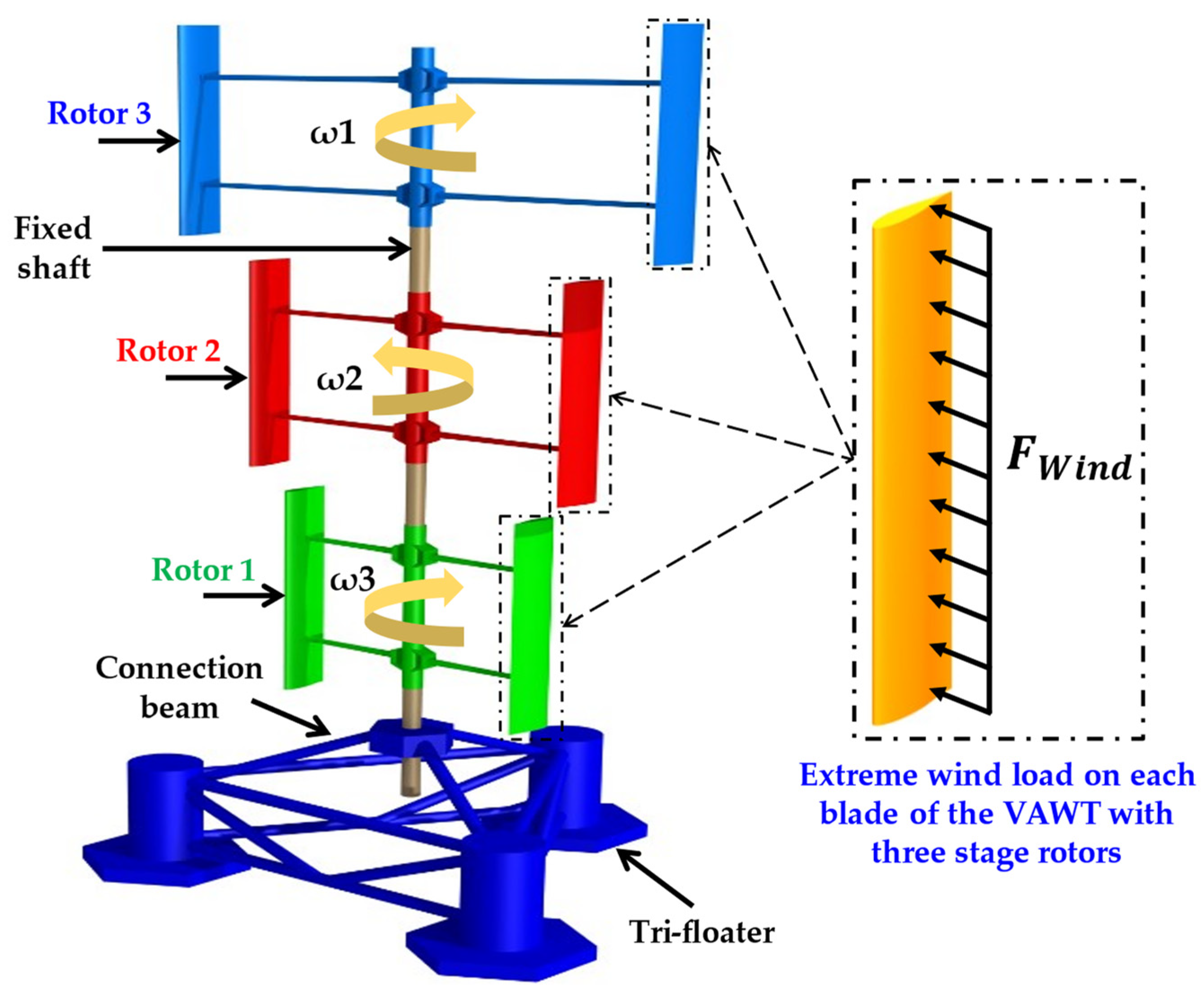
2. Floating Darrieus-Type Wind Turbine with Three-Stage Rotors
3. Materials and Methods
3.1. Abaqus Code
3.2. Validation of Abaqus Code
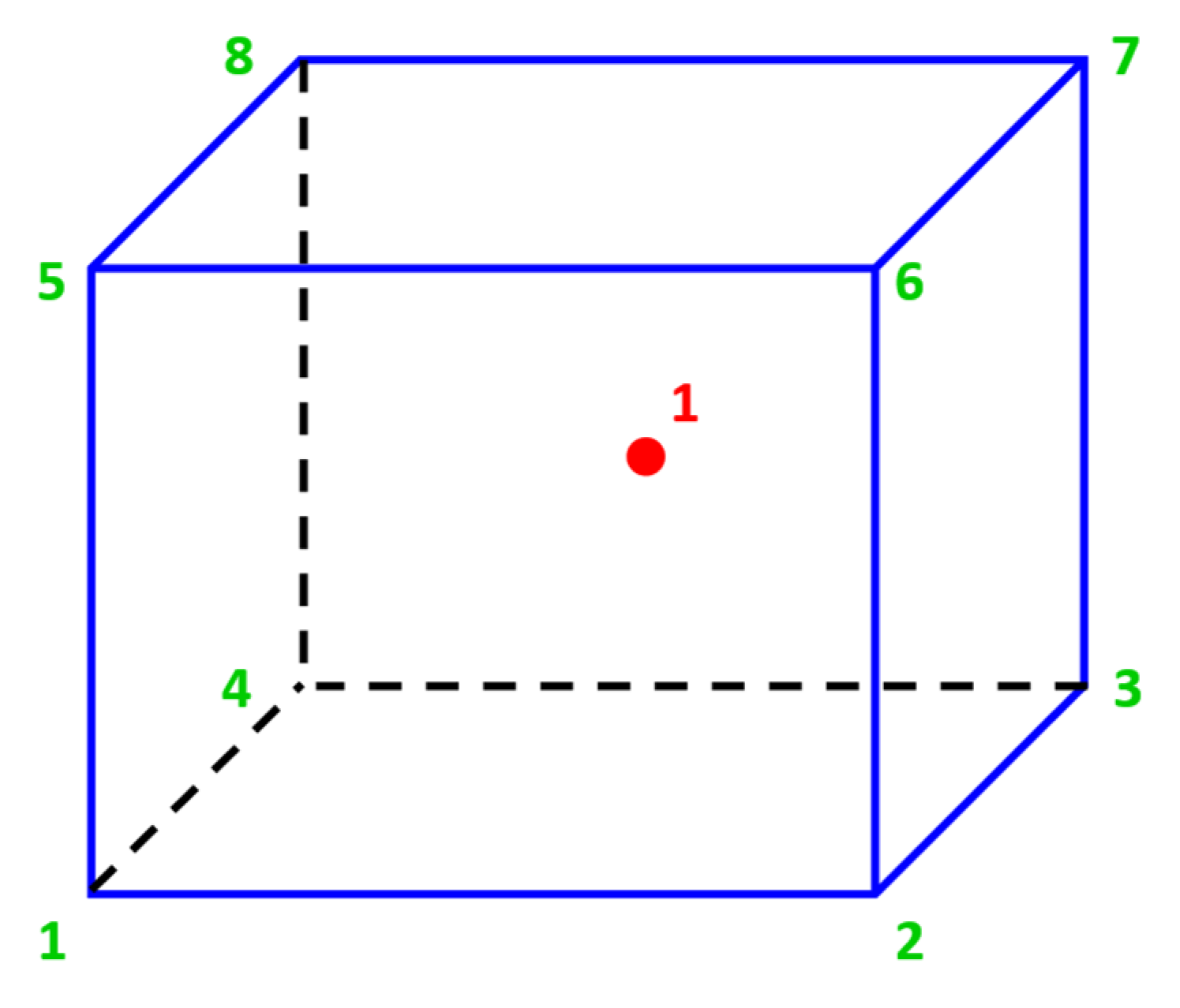
3.2.1. Selecting the Type of Mesh Element
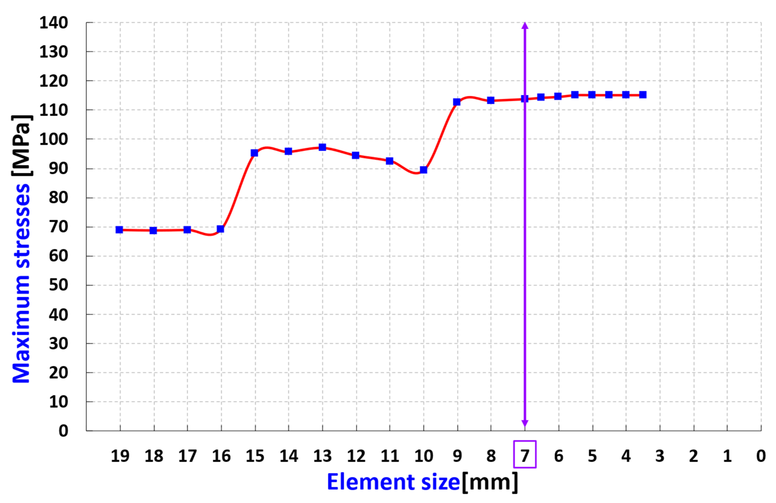
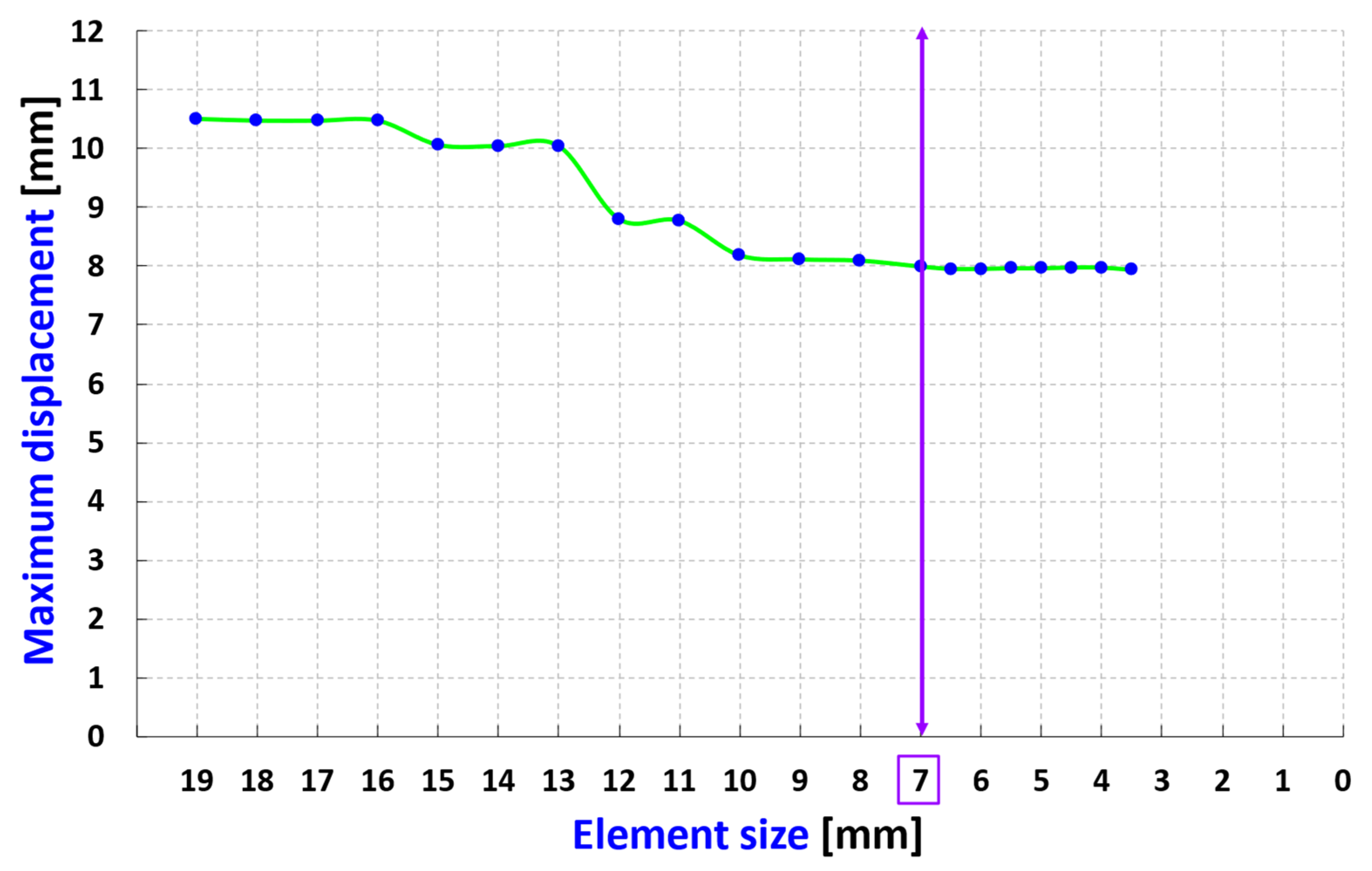
3.2.2. Mesh Convergence Study
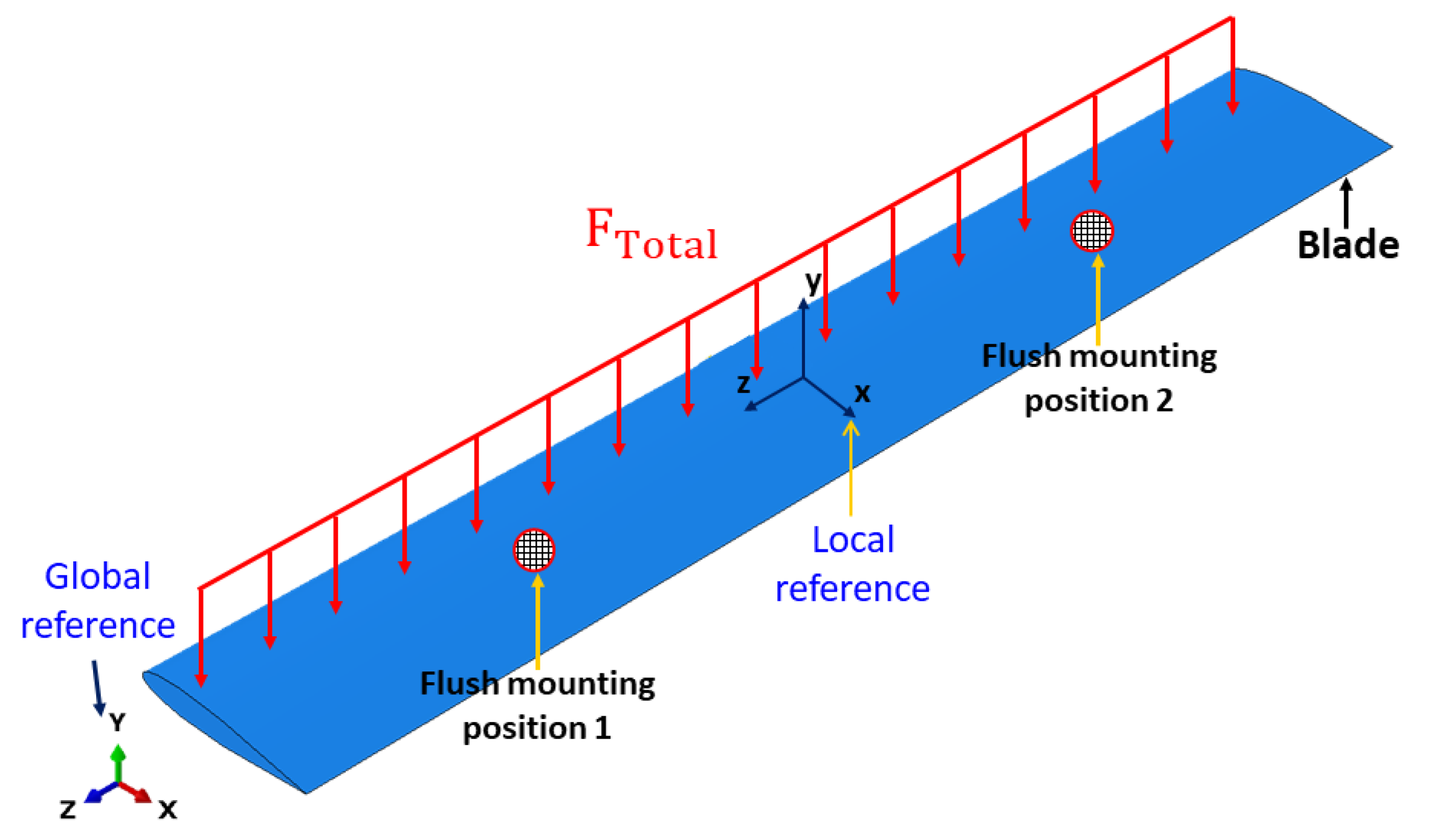
3.3. Geometry and Boundary Conditions
4. Case 1: Blade in Isotropic Material
4.1. Selection of the Appropriate Isotropic Material
4.2. Analytical Calculation of Centrifugal and Total Forces
4.3. Results and Discussion
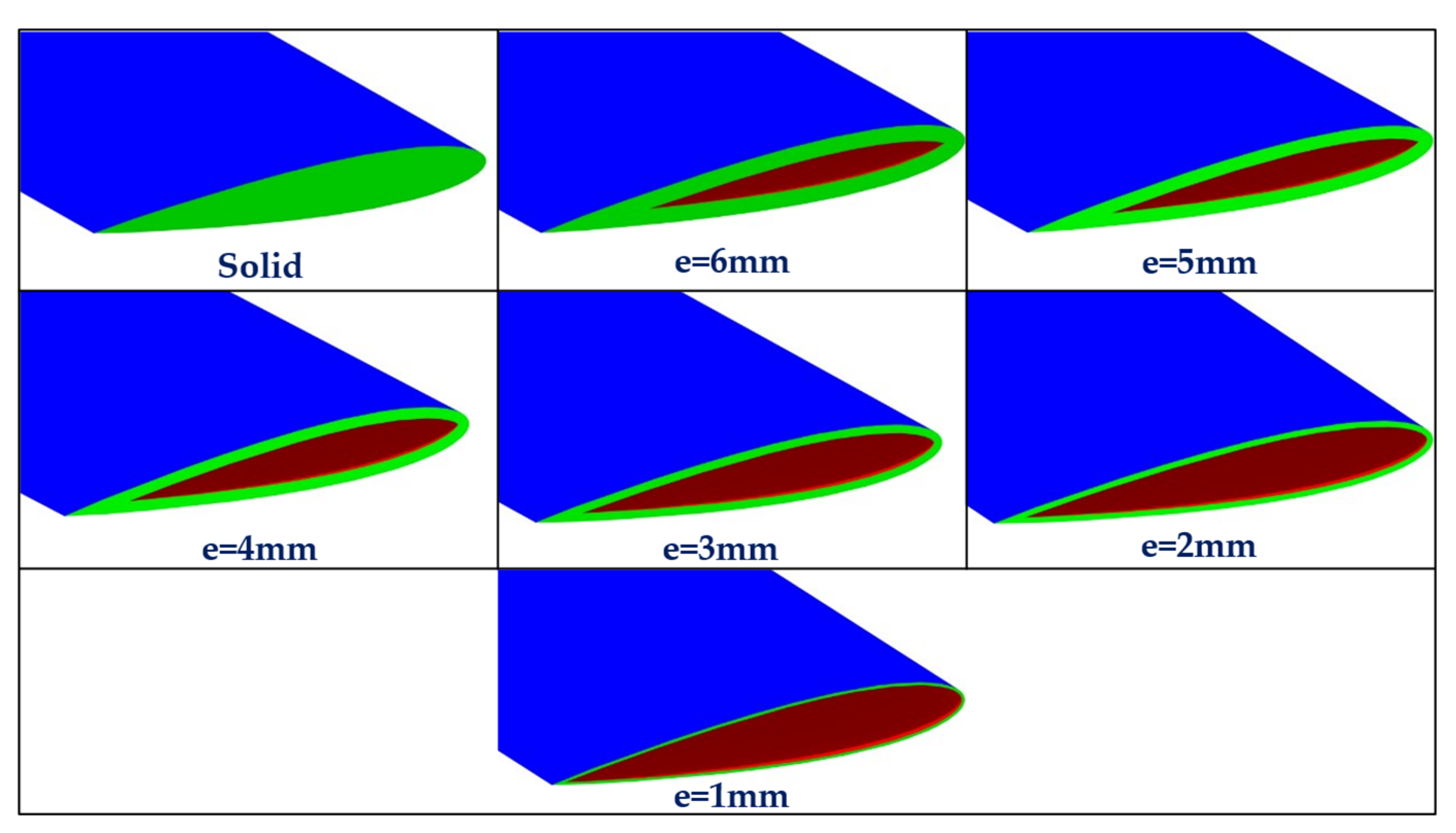
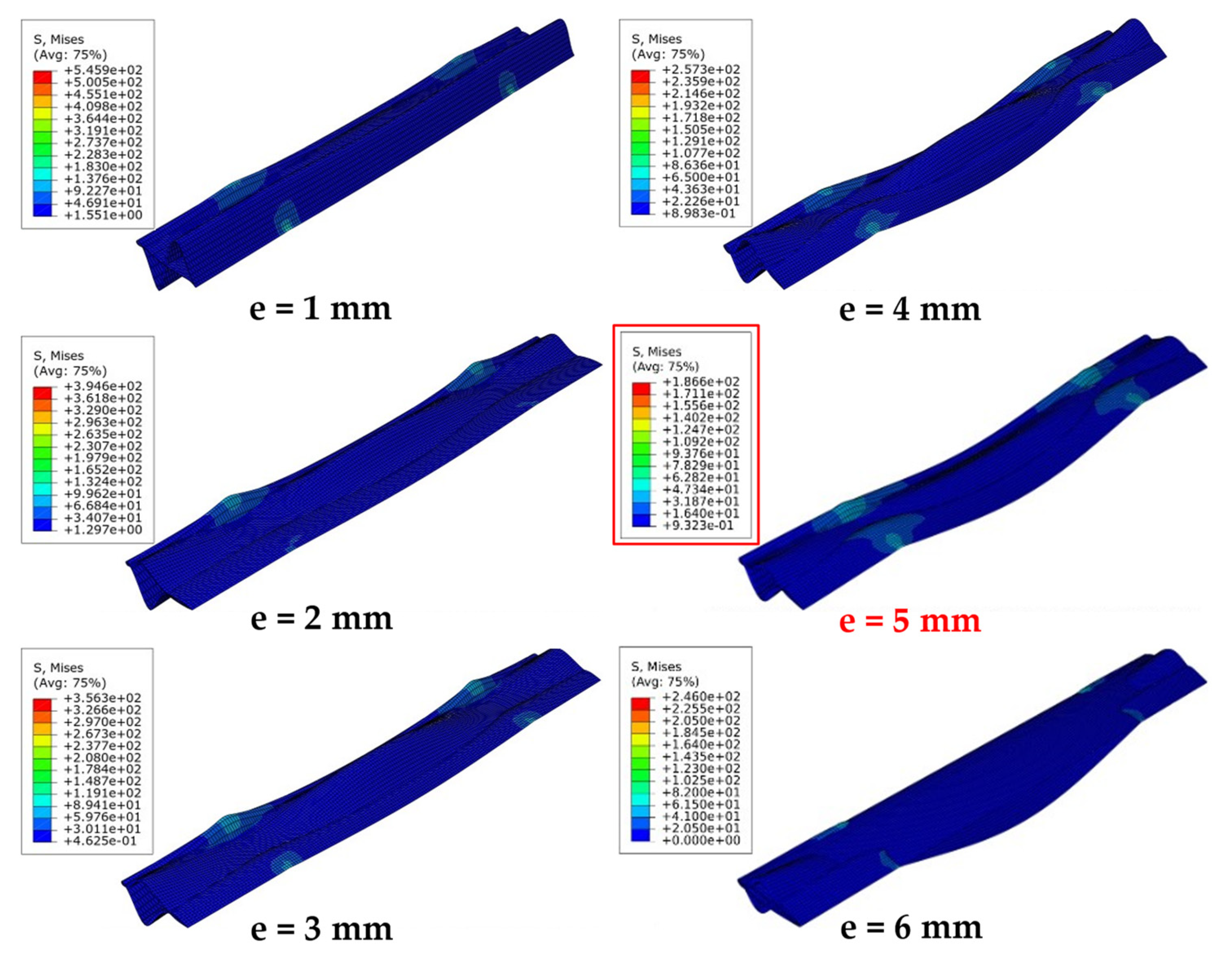
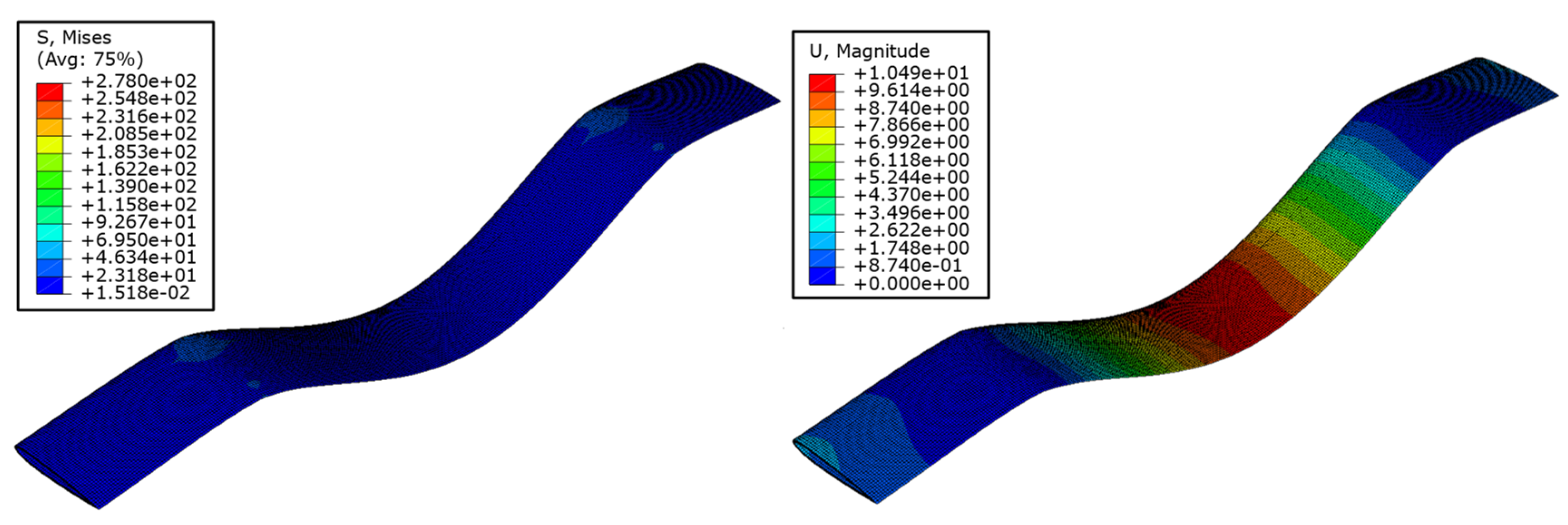
- When the cross-sections of these blades were modeled and analyzed, it was observed that the distortion of the blade shape occurs in the regions of maximum deformations, as shown in Figure 13.
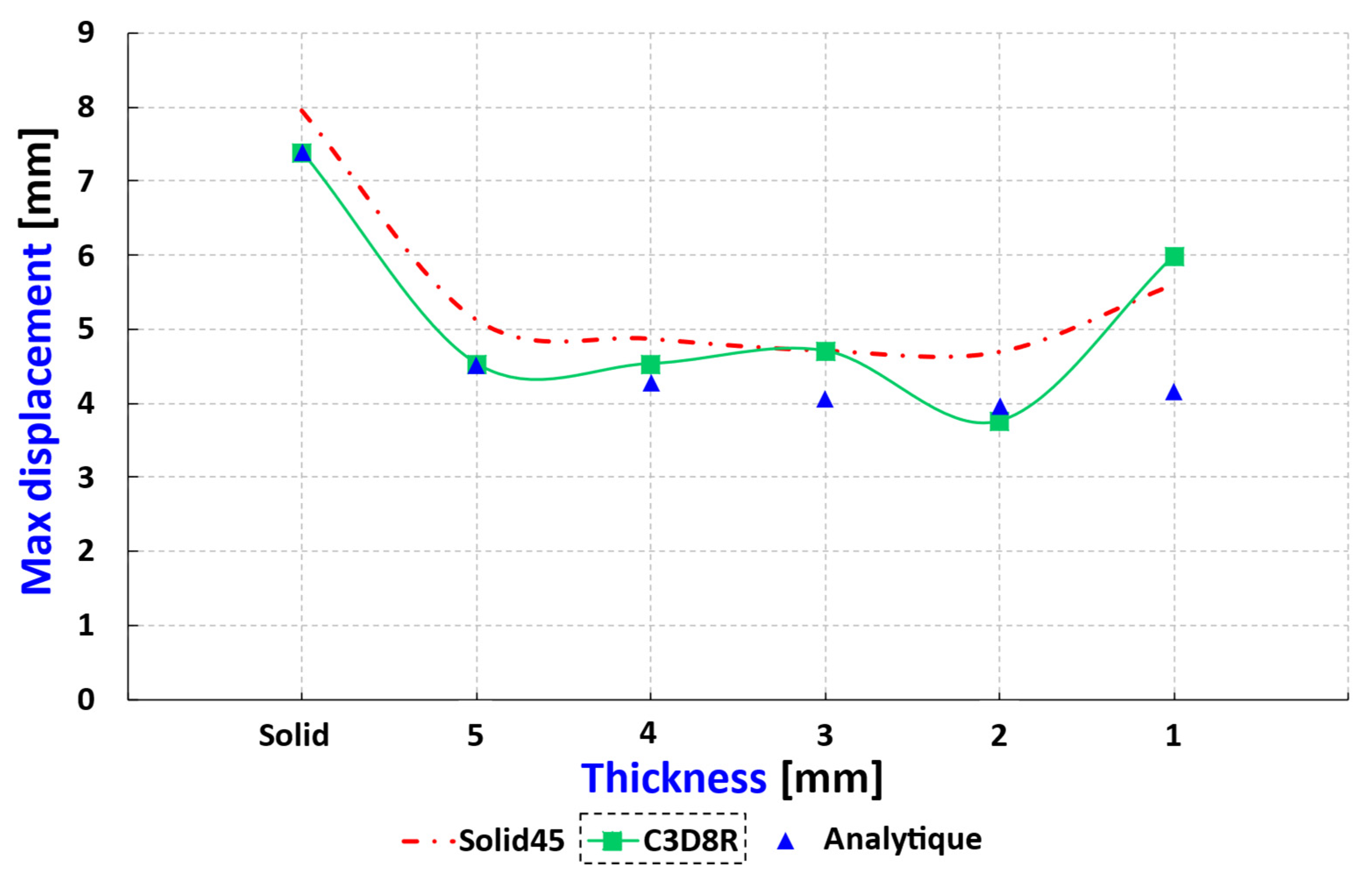
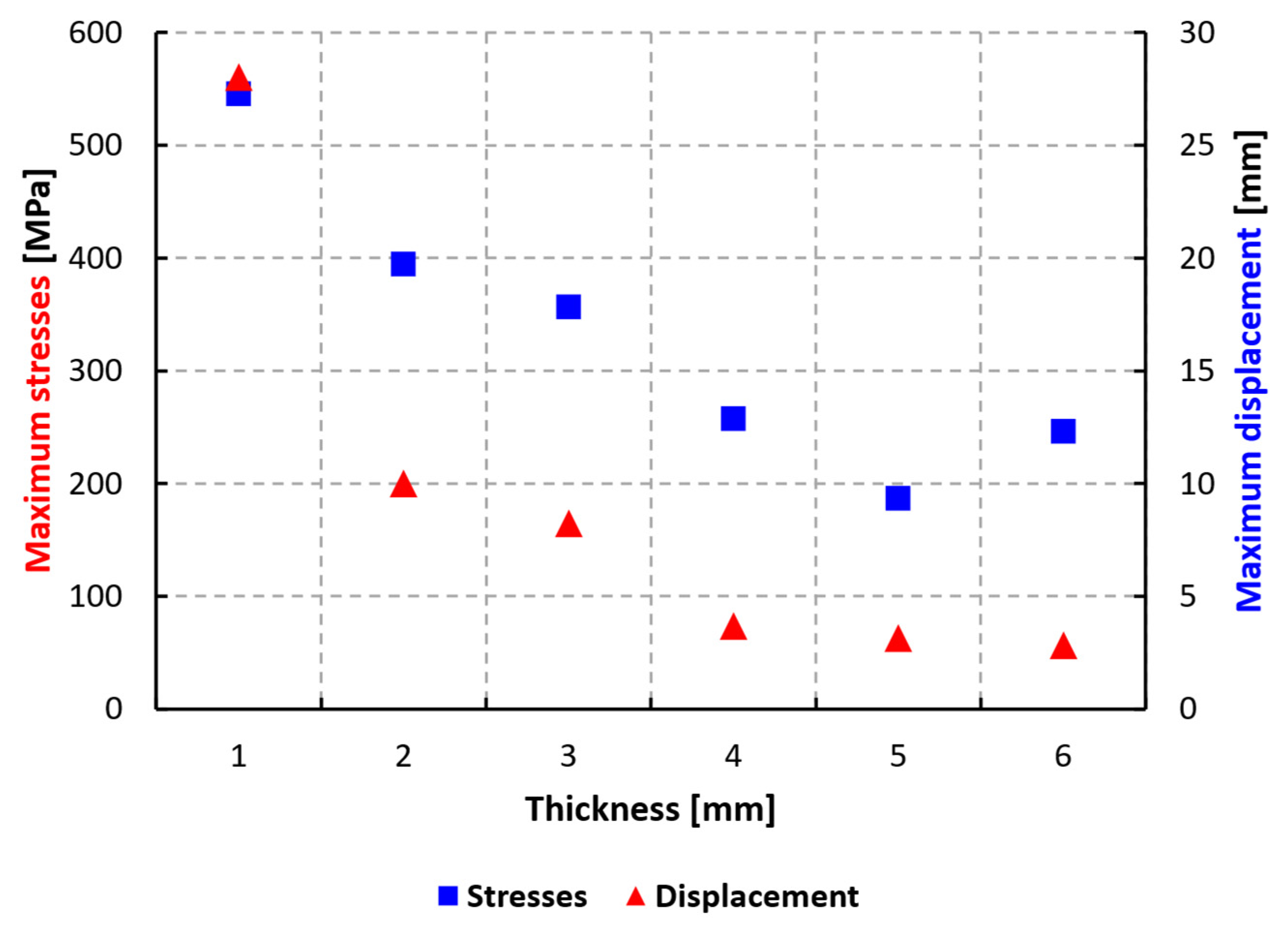
- The values of the maximum displacements and stresses suddenly increase from 4 to 1 mm thickness. This is due to the large deformation of the blade shape. The C3D8R element type gives a better approximation of the large deformation of the blade shape.
- The distortion of the blade shape decreases with increasing thickness.
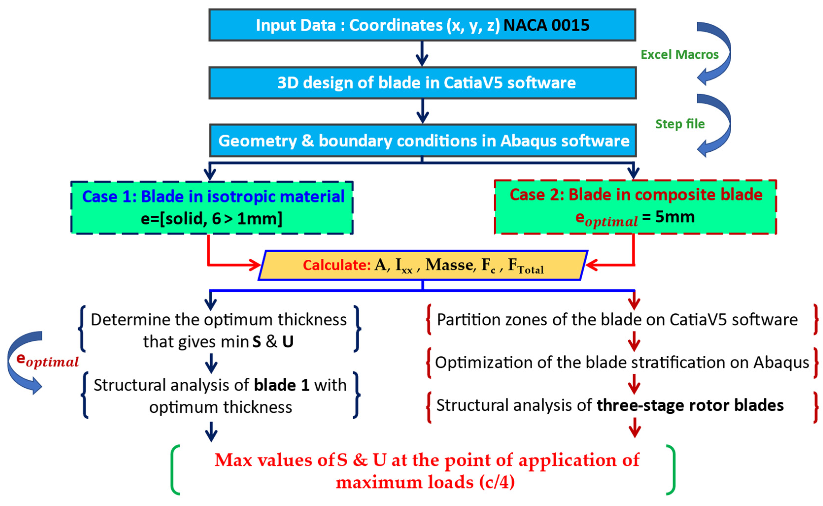
- The optimum value for the thickness of rotor blade 1 is 5 mm because this value considerably reduces the maximum stresses and displacements applied to the blade, as well as reducing their weight. In the case of using an orthotropic material, this optimal thickness value will be used.
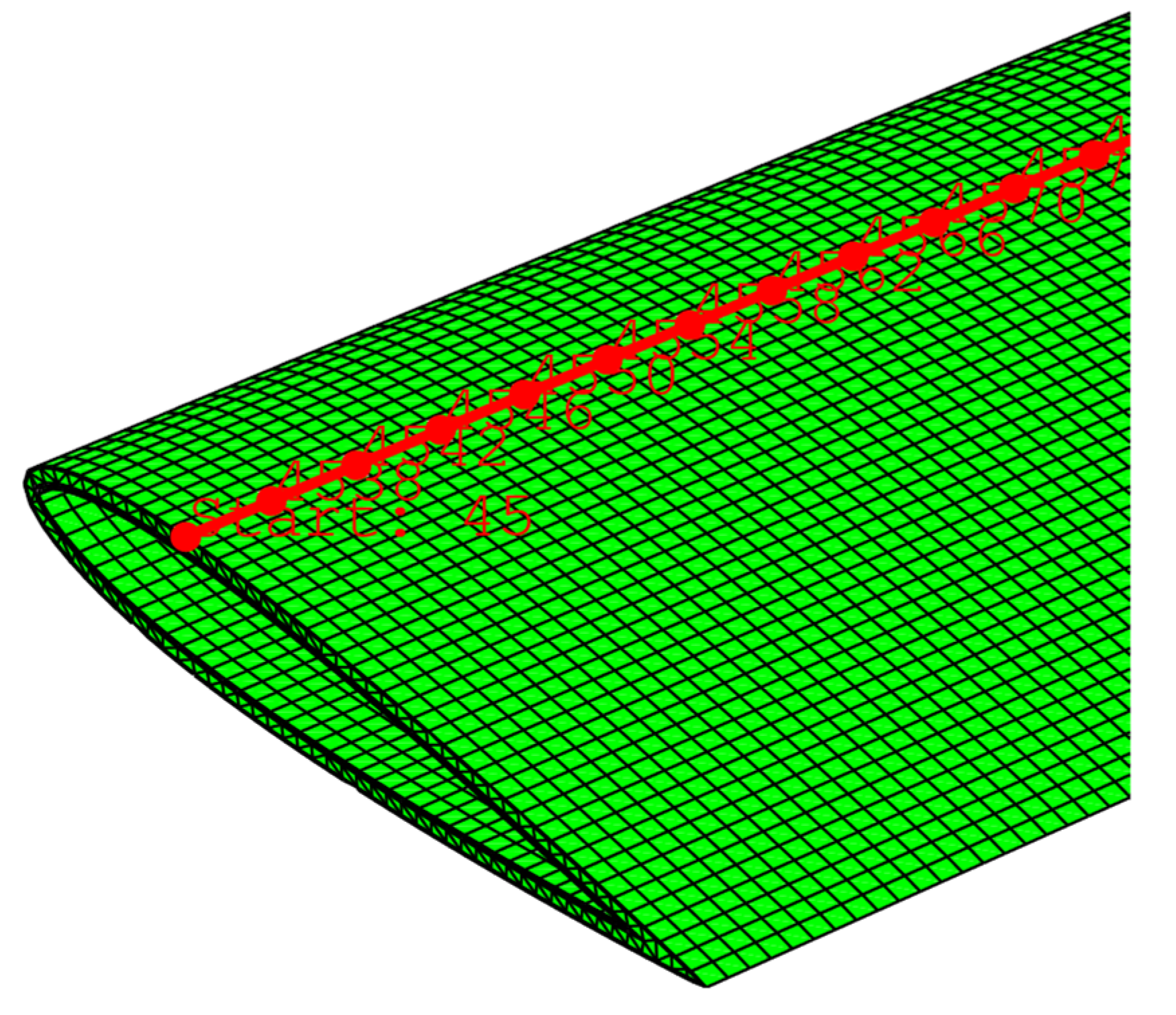
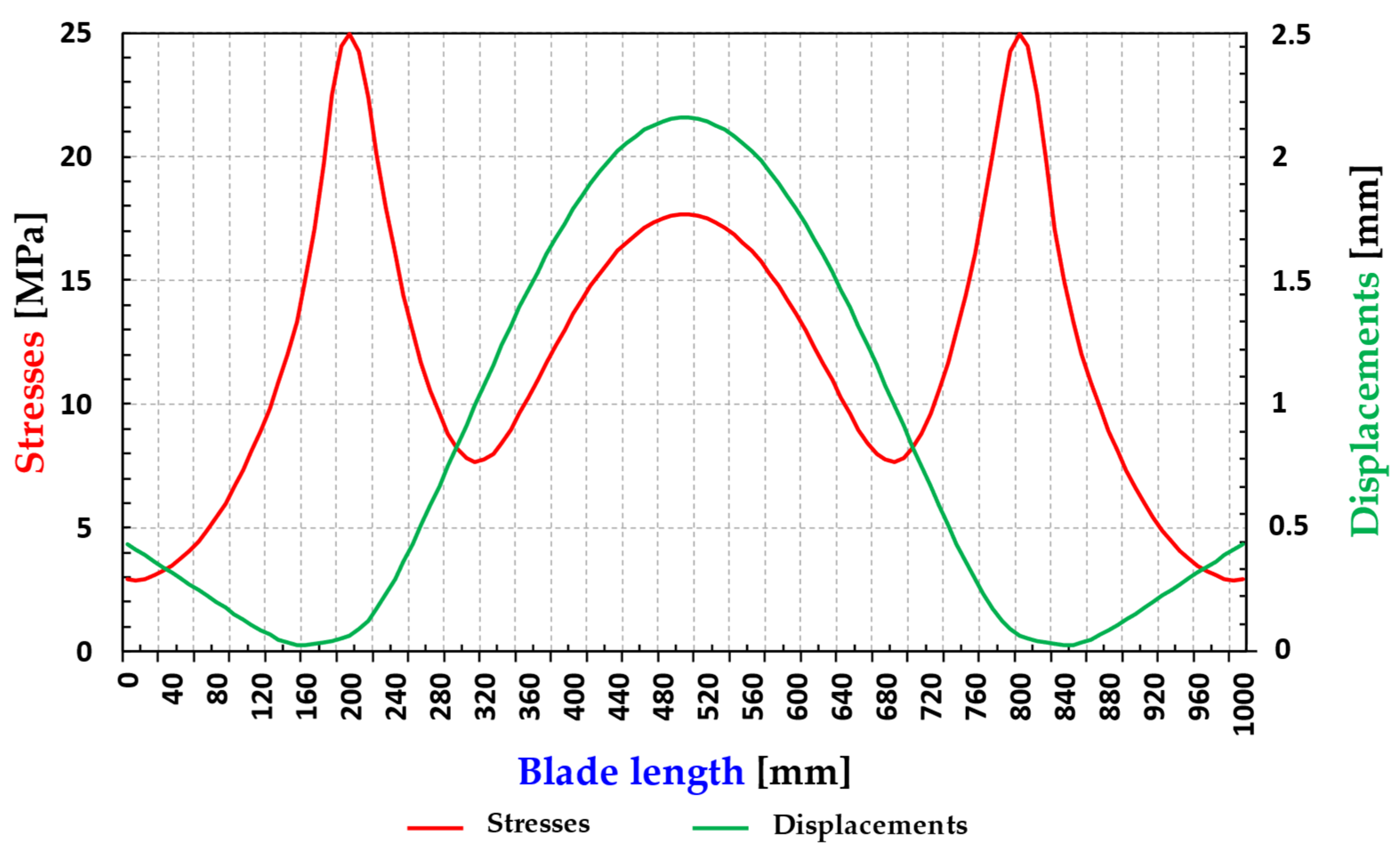
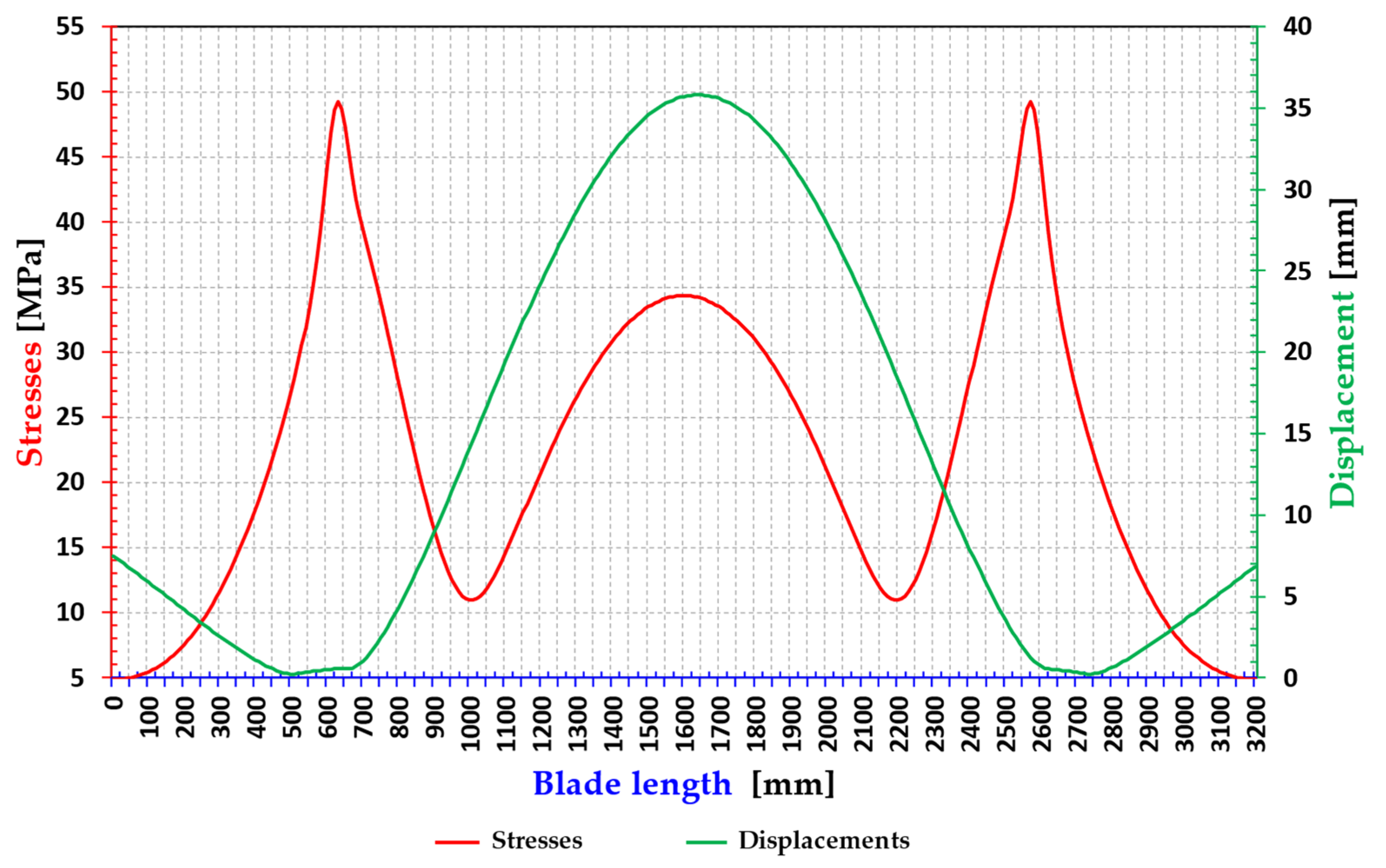
- A plot is considered by selecting all nodes along the quarter chord (see Figure 12).
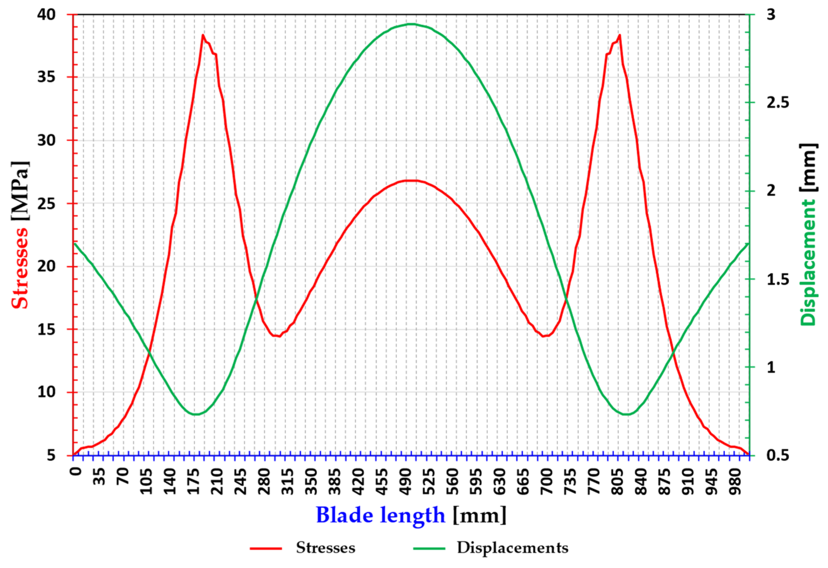
- As shown in Figure 14, the maximum values of the stress variation and displacements of rotor blade 1 of an optimum thickness of 5 mm are evaluated at the point of the application of maximum loads (c/4) along the length of the blade.
- The maximum stresses are located at positions 200 and 900 mm of the blade length; therefore, the maximum displacements are in the middle of the blade at the position of 625 mm.
- The yield strength of aluminum EN AW-2017 is in the range of 295 MPa (see Table 2) and according to Figure 11 of stress distribution, the Max stress is approximately 186.581 MPa, does not exceed the yield strength of the material, and thus the blade operates in the elastic range which allows it to withstand the extreme loads applied without suffering from cracking or breaking.
- The maximum displacement is approximately 3.150 mm, which is low compared to the dimension of the blade.
5. Case 2: Composite Blade
5.1. Selection of the Appropriate Composite Material
5.2. Comparative Study of Aluminum and Glass–Epoxy
5.3. Calculation of Centrifugal and Total Forces
5.4. Zones of Partition and Stratification of the Blade
5.5. Results
5.5.1. Optimization of Laminates
5.5.2. Stresses and Displacements of the Composite Blades of Three Rotors

| Rotor 1 | |||
| S | Smax (MPa) | Smin (MPa) | Unidirectional Resistance (MPa) |
| Sx | 6.35 | −1.707 | 1080 |
| Sy | −0.274 | −1.07 | 64 |
| Sz | 3.914 | −13.768 | - |
| Seq | 14.654 | 0.952 | - |
| Rotor 2 | |||
| S | Smax (MPa) | Smin (MPa) | Unidirectional Resistance (MPa) |
| Sx | −4.687 | −6.154 | 1080 |
| Sy | −3.431 | −4.555 | 64 |
| Sz | 26.665 | −23.224 | - |
| Seq | 33.496 | 10.122 | - |
| Rotor 3 | |||
| S | Smax (MPa) | Smin (MPa) | Unidirectional Resistance (MPa) |
| Sx | −0.8924 | −2.6029 | 1080 |
| Sy | 1.01719 | −1.5678 | 64 |
| Sz | 37.5321 | −35.4675 | - |
| Seq | 49.2314 | 4.899 | - |
5.6. Discussion of the Results
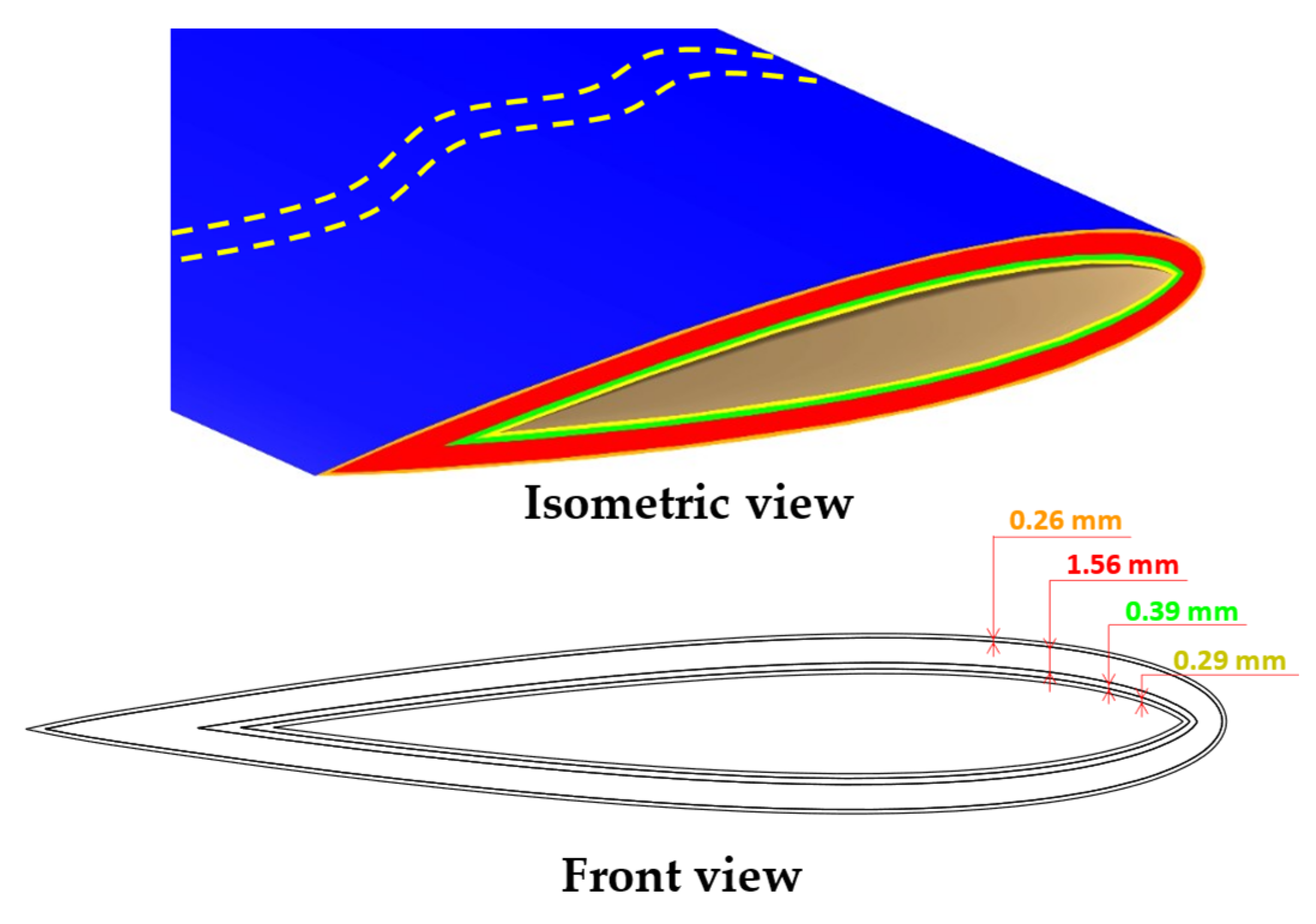
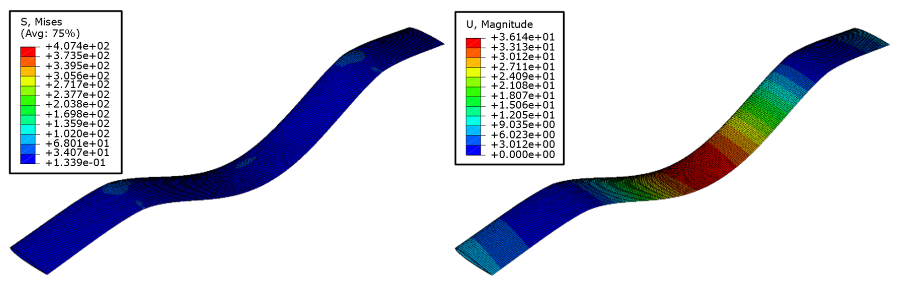
- In order to achieve a high strength-to-weight ratio for H-Darrieus-type floating wind turbine blades with three-stage rotors, they are modeled with a glass–epoxy composite material and different combinations of layers/ply orientations are analyzed. The appropriate combination of layers is found with an optimized number of layers in each direction and with varying thicknesses.
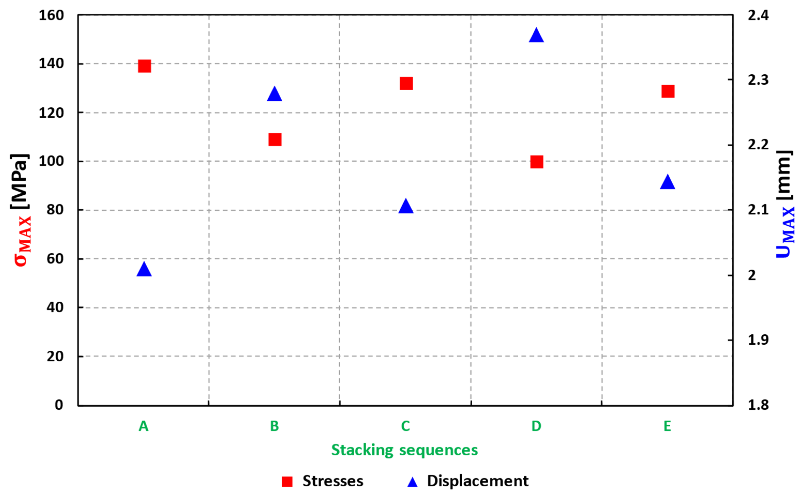
- Keeping more layers in 90-degree directions reduces the value of maximum stresses and displacements because the applied load is normal to the chord and span of the blade. Therefore, more layers in the 90-degree direction carry the load.
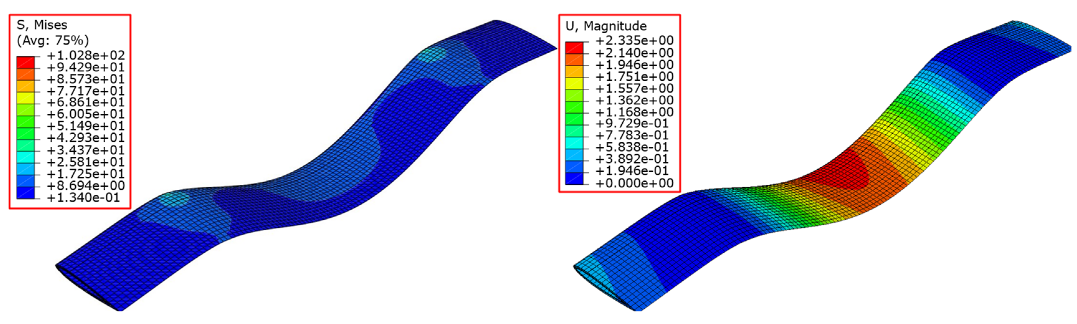
- The maximum values of stresses and displacements are evaluated at the location where the maximum loads are applied and compared to the unidirectional strength of the glass/epoxy.
- The complete model of the three-stage rotor H-Darrieus floating wind turbine rotor 1 composite blade with an appropriate stacking sequence has maximum stresses of 103.8 MPa and maximum displacements of 2335 mm which are lower than these values (186.581 MPa and 3150 mm) for the same 5 mm aluminum wall thickness blade. Then, we applied this same stacking sequence for the composite blades of rotors 2 and 3 of the H-Darrieus floating wind turbines with three rotor stages.
6. Conclusions
Author Contributions
Funding
Institutional Review Board Statement
Informed Consent Statement
Data Availability Statement
Conflicts of Interest
References
- Nachtane, M.; Tarfaoui, M.; Goda, I.; Rouway, M. A review on the technologies, design considerations and numerical models of tidal current turbines. Renew. Energy 2020, 157, 1274–1288. [Google Scholar] [CrossRef]
- Nachtane, M.; Tarfaoui, M.; Saifaoui, D.; El Moumen, A.; Hassoon, O.H.; Benyahia, H. Evaluation of durability of composite materials applied to renewable marine energy: Case of ducted tidal turbine. Energy Rep. 2018, 4, 31–40. [Google Scholar] [CrossRef]
- Rouway, M.; Nachtane, M.; Tarfaoui, M.; Chakhchaoui, N.; Omari, L.E.H.; Fraija, F.; Cherkaoui, O. Mechanical Properties of a Biocomposite Based on Carbon Nanotube and Graphene Nanoplatelet Reinforced Polymers: Analytical and Numerical Study. J. Compos. Sci. 2021, 5, 234. [Google Scholar] [CrossRef]
- Nachtane, M.; Tarfaoui, M.; Sassi, S.; El Moumen, A.; Saifaoui, D. An investigation of hygrothermal aging effects on high strain rate behaviour of adhesively bonded composite joints. Compos. Part B Eng. 2019, 172, 111–120. [Google Scholar] [CrossRef]
- Tarfaoui, M.; Nachtane, M.; Khadimallah, H.; Saifaoui, D. Simulation of Mechanical Behavior and Damage of a Large Composite Wind Turbine Blade under Critical Loads. Appl Compos. Mater. 2018, 25, 237–254. [Google Scholar] [CrossRef]
- Lagdani, O.; Tarfaoui, M.; Nachtane, M.; Trihi, M.; Laaouidi, H. A numerical investigation of the effects of ice accretion on the aerodynamic and structural behavior of offshore wind turbine blade. Wind Eng. 2021, 45, 1433–1446. [Google Scholar] [CrossRef]
- Shah, O.R.; Tarfaoui, M. The Identification of Structurally Sensitive Zones Subject to Failure in a Wind Turbine Blade Using Nodal Displacement Based Finite Element Sub-Modeling. Renew. Energy 2016, 87, 168–181. [Google Scholar] [CrossRef]
- Lagdani, O.; Tarfaoui, M.; Nachtane, M.; Trihi, M.; Laaouidi, H. Modal analysis of an iced offshore composite wind turbine blade. Wind Eng. 2021, 46, 134–149. [Google Scholar] [CrossRef]
- IEC IEC 61400-1:2019 IEC Webstore. Rural Electrification, Wind Power. Available online: https://webstore.iec.ch/publication/26423 (accessed on 19 March 2022).
- Fanucci, J.B.; Walter, R.E. Innovative Wind Machines: The Theoretical Performance of a Vertical-Axis Wind Turbine. In Proceedings of the Vertical-Axis Wind Turbine Technology Workshop, Albuquerque, NM, USA, 17 May 1976; Volume 3, pp. 61–95. [Google Scholar]
- Miliket, T.A.; Ageze, M.B.; Tigabu, M.T. Aerodynamic Performance Enhancement and Computational Methods for H-Darrieus Vertical Axis Wind Turbines: Review. Int. J. Green Energy 2022, 1–38. [Google Scholar] [CrossRef]
- Hand, B.; Kelly, G.; Cashman, A. Structural Analysis of an Offshore Vertical Axis Wind Turbine Composite Blade Experiencing an Extreme Wind Load. Mar. Struct. 2021, 75, 102858. [Google Scholar] [CrossRef]
- Rahman, M.; Whyte, O.; Ilie, M.; Soloiu, V.; Molina, G. Structural and Aerodynamic Characteristics Analysis of a Small V-Shaped Vertical Axis Wind Turbine Rotor. Int. J. Green Energy 2022, 19, 279–299. [Google Scholar] [CrossRef]
- Elhenawy, Y.; Fouad, Y.; Marouani, H.; Bassyouni, M. Performance Analysis of Reinforced Epoxy Functionalized Carbon Nanotubes Composites for Vertical Axis Wind Turbine Blade. Polymers 2021, 13, 422. [Google Scholar] [CrossRef] [PubMed]
- Tarfaoui, M.; Shah, O.R.; Nachtane, M. Design and optimization of composite offshore wind turbine blades. J. Energy Resour. Technol. 2019, 141, 051204. [Google Scholar] [CrossRef]
- Tarfaoui, M.; Khadimallah, H.; Imad, A.; Pradillon, J.Y. Design and Finite Element Modal Analysis of 48m Composite Wind Turbine Blade. Appl. Mech. Mater. 2012, 146, 170–184. [Google Scholar]
- Tarfaoui, M.; Nachtane, M.; Boudounit, H. Finite Element Analysis of Composite Offshore Wind Turbine Blades Under Operating Conditions. J. Therm. Sci. Eng. Appl 2020, 12, 011001. [Google Scholar] [CrossRef]
- Li, B.Y.; Karri, N.; Wang, Q. Three-dimensional numerical analysis on blade response of a vertical-axis tidal current turbine under operational conditions. J. Renew. Sustain. Energy 2014, 6, 043123. [Google Scholar] [CrossRef]
- Marsh, P.; Ranmuthugala, D.; Penesis, I.; Thomas, G. Numerical simulation of the loading characteristics of straight and helical-bladed vertical axis tidal turbines. Renew. Energy 2016, 94, 418–428. [Google Scholar] [CrossRef][Green Version]
- Sutherland, H.J.; Berg, D.E.; Ashwill, T.D. A retrospective of VAWT technology; SAND2012-0304. In Technical Report Sandia National Laboratories; Sandia National Laboratories: Albuquerque, NM, USA; Livermore, CA, USA, 2012. [Google Scholar]
- Van Den Avyle, J.A.; Sutherland, H.J. Fatigue characterization of a VAWT blade material. In Proceedings of the Eighth ASME Wind Energy Symposium, Houston, TX, USA, 22–25 January 1989; Volume 7, pp. 125–129. [Google Scholar]
- Berg, D.E. Structural Design of the Sandia 34-Meter Vertical-Axis Wind Turbine; Technical Report; Sandia National Laboratories: Albuquerque, NM, USA, 1985. [Google Scholar]
- Dabachi, M.A.; Rahmouni, A.; Bouksour, O. Design and Aerodynamic Performance of New Floating H-Darrieus Vertical Axis Wind Turbines. Mater. Today Proc. 2020, 30, 899–904. [Google Scholar] [CrossRef]
- Dabachi, M.A.; Rahmouni, A.; Rusu, E.; Bouksour, O. Aerodynamic Simulations for Floating Darrieus-Type Wind Turbines with Three-Stage Rotors. Inventions 2020, 5, 18. [Google Scholar] [CrossRef]
- Nachtane, M.; Tarfaoui, M.; El Moumen, A.; Saifaoui, D. Damage prediction of horizontal axis marine current turbines under hydrodynamic, hydrostatic and impacts loads. Compos. Struct. 2017, 170, 146–157. [Google Scholar] [CrossRef]
- Lagdani, O.; Tarfaoui, M.; Rouway, M.; Laaouidi, H.; Sbai, S.J.; Dabachi, M.A.; Aamir, A.; Nachtane, M. Influence of Moisture Diffusion on the Dynamic Compressive Behavior of Glass/Polyester Composite Joints for Marine Engineering Applications. J. Compos. Sci. 2022, 6, 94. [Google Scholar] [CrossRef]
- Hameed, M.S.; Afaq, S.K. Design and Analysis of a Straight Bladed Vertical Axis Wind Turbine Blade Using Analytical and Numerical Techniques. Ocean Eng. 2013, 57, 248–255. [Google Scholar] [CrossRef]
- Three-Dimensional Solid Element Library. Available online: https://abaqus-docs.mit.edu/2017/English/SIMACAEELMRefMap/simaelm-r-3delem.htm (accessed on 19 March 2022).
- Anderson, J.D., Jr. Fundamentals of Aerodynamics; Tata McGraw-Hill Education: New York, NY, USA, 2010. [Google Scholar]
- Emami, M.R. Aerodynamic Forces on an Airfoil; AER 303F; Aerospace Laboratory I University of Toronto: Toronto, ON, Canada, 2007. [Google Scholar]
- Batz—Burgel. Al EN AW-2017A (AlCu4MgSi—3.1325) Aluminium. Available online: https://batz-burgel.com/en/metal-trading/aluminium-product-range/en-aw-2017a/ (accessed on 3 March 2022).
- Islam, M.; Fartaj, A.; Carriveau, R. Analysis of the Design Parameters Related to a Fixed-Pitch Straight-Bladed Vertical Axis Wind Turbine. Wind Eng. 2008, 32, 491–507. [Google Scholar] [CrossRef]
- Sutherland, H.J. A Summary of the Fatigue Properties of Wind Turbine Materials. Wind Energy Int. J. Prog. Appl. Wind Power Convers. Technol. 2000, 3, 1–34. [Google Scholar] [CrossRef]
- Wang, L.; Kolios, A.; Nishino, T.; Delafin, P.-L.; Bird, T. Structural Optimisation of Vertical-Axis Wind Turbine Composite Blades Based on Finite Element Analysis and Genetic Algorithm. Compos. Struct. 2016, 153, 123–138. [Google Scholar] [CrossRef]
- Barnes, R.H.; Morozov, E.V. Structural Optimisation of Composite Wind Turbine Blade Structures with Variations of Internal Geometry Configuration. Compos. Struct. 2016, 152, 158–167. [Google Scholar] [CrossRef]
- Gay, D.; Hoa, S.V.; Tsai, S.W. Composite Materials: Design and Applications; CRC Press: Boca Raton, FL, USA, 2002; ISBN 978-0-429-13496-8. [Google Scholar]
- Navadeh, N.; Goroshko, I.; Zhuk, Y.; Etminan Moghadam, F.; Soleiman Fallah, A. Finite Element Analysis of Wind Turbine Blade Vibrations. Vibration 2021, 4, 310–322. [Google Scholar] [CrossRef]
- Hameed, M.S.; Afaq, S.K.; Shahid, F. Finite Element Analysis of a Composite VAWT Blade. Ocean Eng. 2015, 109, 669–676. [Google Scholar] [CrossRef]
- El Moumen, A.; Tarfaoui, M.; Hassoon, O.; Lafdi, K.; Benyahia, H.; Nachtane, M. Experimental study and numerical modelling of low velocity impact on laminated composite reinforced with thin film made of carbon nanotubes. Appl. Compos. Mater. 2018, 25, 309–320. [Google Scholar] [CrossRef]


| Thickness (mm) | Max. Displacement (mm) | Error % Compared to Analytical | |||
|---|---|---|---|---|---|
| Solid45 Ansys [27] | C3D8R Abaqus | Analytical [27] | Solid45 Ansys [27] | C3D8R Abaqus | |
| Solid | 7.947 | 7.392 | 7.39 | 7.54 | 0.03 |
| 5 | 5.123 | 4.532 | 4.51 | 13.59 | 0.48 |
| 4 | 4.864 | 4.532 | 4.27 | 13.91 | 5.95 |
| 3 | 4.703 | 4.705 | 4.07 | 15.55 | 14.47 |
| 2 | 4.689 | 3.756 | 3.97 | 18.11 | 5.6 |
| 1 | 5.603 | 5.989 | 4.17 | 34.36 | 35.81 |
| Properties | Yield Strength (MPa) | Breaking Strength (MPa) | Young’s Modulus (GPa) | Poisson’s Ratio (-) | Density (kg/m3) |
|---|---|---|---|---|---|
| Values | 295 | 470 | 70 | 0.346 | 2710 |
| Rotor 1 | |||||
|---|---|---|---|---|---|
| Thickness (mm) | A (m2) (10−3) | Ixx (m2) (10−3) | Masse (kg) | Fc (KN) | FTotal (KN) |
| Solid | 2.000 | 6.733 | 6.262 | 11.364 | 11.678 |
| 6 | 2.000 | 6.271 | 4.276 | 7.759 | 8.703 |
| 5 | 1.000 | 5.880 | 3.679 | 6.676 | 6.990 |
| 4 | 1.000 | 5.297 | 3.033 | 5.504 | 5.818 |
| 3 | 0.863 | 4.472 | 2.339 | 4.244 | 4.558 |
| 2 | 0.590 | 3.352 | 1.600 | 2.903 | 3.217 |
| 1 | 0.302 | 1.881 | 0.819 | 1.486 | 1.800 |
| Thickness (mm) | Mass (kg) | Max Stresses (MPa) | Max Displacements (mm) |
|---|---|---|---|
| Solid | 6.262 | 193.979 | 4.489 |
| 6 | 4.276 | 246.004 | 2.843 |
| 5 | 3.679 | 186.581 | 3.150 |
| 4 | 3.033 | 257.295 | 3.674 |
| 3 | 2.339 | 356.270 | 8.246 |
| 2 | 1.600 | 394.573 | 9.996 |
| 1 | 0.819 | 545.851 | 28.032 |
| 45 × 103 | 12 × 103 | 0.3 | 0.2 | 4.5 × 10³ | 5 × 10³ |
| Rotor 1 | ||||||||
|---|---|---|---|---|---|---|---|---|
| e (mm) | A (m2) (10−3) | Ixx (m2) (10−8) | Mass (kg) | Fc (KN) | FTotal (KN) | |||
| Al | V-Epoxy | Al | V-Epoxy | Al | V-Epoxy | |||
| 6 | 2.000 | 6.271 | 4.276 | 3.124 | 7.759 | 5.669 | 8.703 | 5.983 |
| 5 | 1.000 | 5.880 | 3.679 | 2.688 | 6.676 | 4.878 | 6.990 | 5.192 |
| 4 | 1.000 | 5.297 | 3.033 | 2.216 | 5.504 | 4.021 | 5.818 | 4.335 |
| 3 | 0.863 | 4.472 | 2.339 | 1.709 | 4.244 | 3.101 | 4.558 | 3.415 |
| 2 | 0.590 | 3.352 | 1.600 | 1.169 | 2.903 | 2.121 | 3.217 | 2.435 |
| 1 | 0.302 | 1.881 | 0.819 | 0.598 | 1.486 | 1.085 | 1.800 | 1.399 |
| eoptimal = 5 mm | |||||
|---|---|---|---|---|---|
| Rotors | A (10−3) (m2) | Ixx (10−3) (m2) | Mass (kg) | Fc (kN) | FTotal (kN) |
| 1 | 1 | 5.88 | 2.688 | 4.878 | 5.192 |
| 2 | 2 | 24.18 | 7.630 | 8.179 | 8.997 |
| 3 | 3 | 63.24 | 18.501 | 14.874 | 16.814 |
| Sequences of Stacking | Thickness of Each Laminate (m) | Stresses Max (MPa) | Displacements Max (mm) |
|---|---|---|---|
| A [45°/90°/0°/−45°]s | 0.0005 | 139 | 2.010 |
| B [45°/90°/0°/−45°]s | 45°: 0.0005 | 109 | 2.280 |
| 90°: 0.001 | |||
| 0°: 0.0005 | |||
| −45°: 0.0005 | |||
| C [45°/90°/0°/−45°/−90°]s | 45°: 0.00025 | 132 | 2.107 |
| 90°: 0.00075 | |||
| 0°: 0.0005 | |||
| −45°: 0.00075 | |||
| −90°: 0.00025 | |||
| D [45°/90°/0°/−45°]s | 45°: 0.00026 | 102.8 | 2.335 |
| 90°: 0.00156 | |||
| 0°: 0.00039 | |||
| −45°: 0.00029 | |||
| E [45°/90°/0°/−45°/−90°]s | 45°: 0.00026 | 129 | 2.144 |
| 90°: 0.00078 | |||
| 0°: 0.00042 | |||
| −45°: 0.00026 | |||
| −90°: 0.00078 |
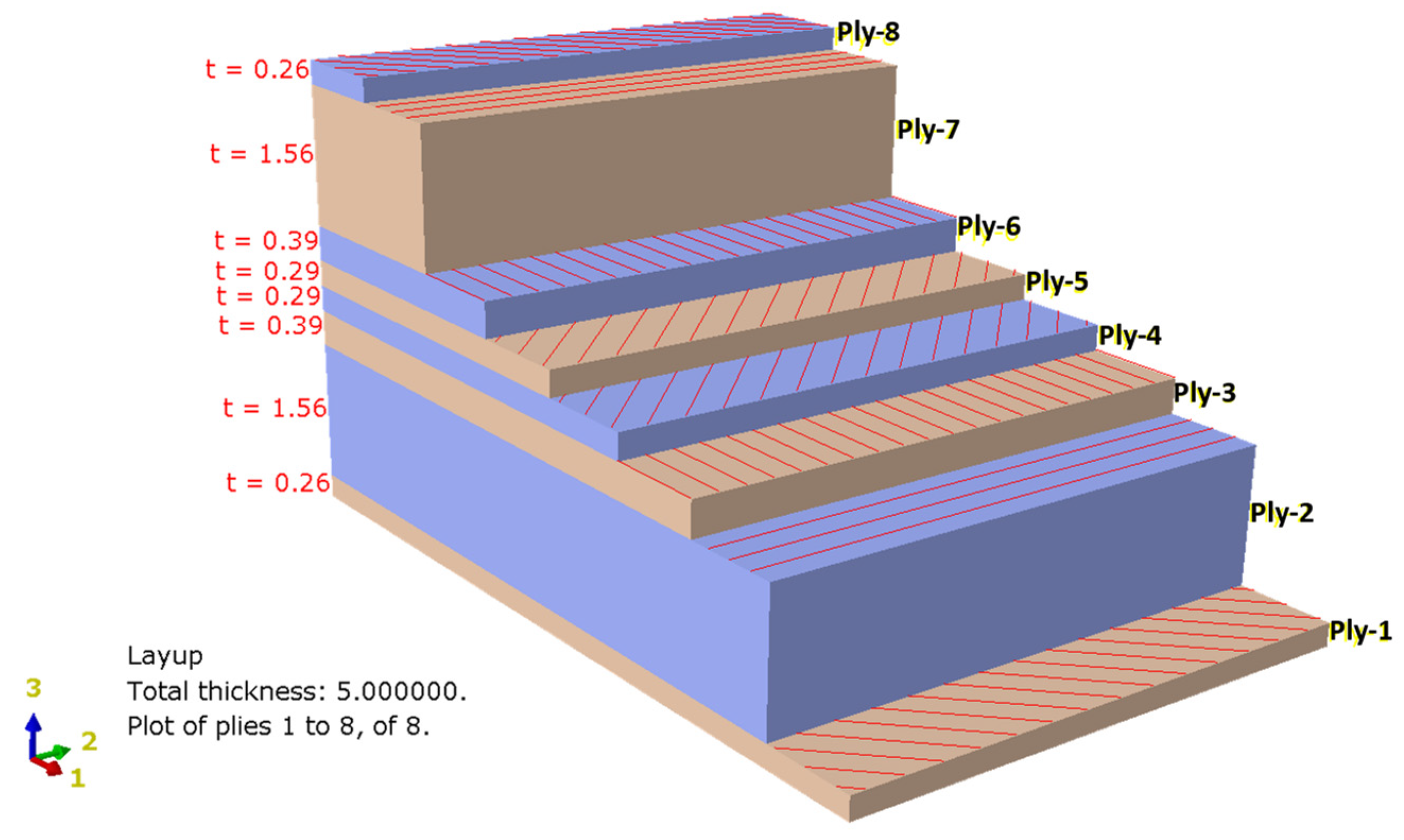
| Layer Number | 1 | 2 | 3 | 4 | 5 | 6 | 7 | 8 |
|---|---|---|---|---|---|---|---|---|
| Orientation (°) | 45 | 90 | 0 | −45 | −45 | 0 | 90 | 45 |
| Thickness (mm) | 0.26 | 1.56 | 0.39 | 0.29 | 0.29 | 0.39 | 1.56 | 0.26 |
| Total Thickness (mm) | 5 | |||||||
Publisher’s Note: MDPI stays neutral with regard to jurisdictional claims in published maps and institutional affiliations. |
© 2022 by the authors. Licensee MDPI, Basel, Switzerland. This article is an open access article distributed under the terms and conditions of the Creative Commons Attribution (CC BY) license (https://creativecommons.org/licenses/by/4.0/).
Share and Cite
Dabachi, M.A.; Rouway, M.; Rahmouni, A.; Bouksour, O.; Sbai, S.J.; Laaouidi, H.; Tarfaoui, M.; Aamir, A.; Lagdani, O. Numerical Investigation of the Structural Behavior of an Innovative Offshore Floating Darrieus-Type Wind Turbines with Three-Stage Rotors. J. Compos. Sci. 2022, 6, 167. https://doi.org/10.3390/jcs6060167
Dabachi MA, Rouway M, Rahmouni A, Bouksour O, Sbai SJ, Laaouidi H, Tarfaoui M, Aamir A, Lagdani O. Numerical Investigation of the Structural Behavior of an Innovative Offshore Floating Darrieus-Type Wind Turbines with Three-Stage Rotors. Journal of Composites Science. 2022; 6(6):167. https://doi.org/10.3390/jcs6060167
Chicago/Turabian StyleDabachi, Mohamed Amine, Marwane Rouway, Abdellatif Rahmouni, Otmane Bouksour, Sara Jamoudi Sbai, Houda Laaouidi, Mostapha Tarfaoui, Abdelwahed Aamir, and Oumnia Lagdani. 2022. "Numerical Investigation of the Structural Behavior of an Innovative Offshore Floating Darrieus-Type Wind Turbines with Three-Stage Rotors" Journal of Composites Science 6, no. 6: 167. https://doi.org/10.3390/jcs6060167
APA StyleDabachi, M. A., Rouway, M., Rahmouni, A., Bouksour, O., Sbai, S. J., Laaouidi, H., Tarfaoui, M., Aamir, A., & Lagdani, O. (2022). Numerical Investigation of the Structural Behavior of an Innovative Offshore Floating Darrieus-Type Wind Turbines with Three-Stage Rotors. Journal of Composites Science, 6(6), 167. https://doi.org/10.3390/jcs6060167