1. Introduction
Over the years, composite sandwich structures, where two composite skins (or facings) are bonded to a lightweight core, have been increasingly used in various areas, ranging from civil and automotive sectors to aerospace and marine applications, because of their high strength-to-weight and stiffness-to-weight ratios, excellent energy-absorbing capability and good corrosion properties [
1]. A major limitation of sandwich composites is their high vulnerability to localised damage caused by foreign object impacts, which inevitably occur during manufacturing, transport, construction and maintenance [
2]. In particular, the damage generated by low-velocity impacts may be difficult or impossible to detect by visual inspection, since it often initiates and grows within the impacted composite facing without any evident dent or crack on the surface. This type of damage, known in aerospace applications as barely visible impact damage—BVID [
3], can have a detrimental effect on the strength of the sandwich composite and lead to the ultimate collapse of the whole structure [
4].
In recent years, the need to prevent failures and reduce the extent of costly and time-consuming experimental testing has called for reliable simulation and design tools capable of predicting the damage generated by impacts on sandwich composite structures. For this reason, a number of combined experimental and numerical investigations have been conducted to characterize the response of sandwich composites to low-velocity impacts as a preliminary step for the development and validation of physically-based damage modelling approaches. A significant amount of this research work has specifically addressed the impact damage behaviour of sandwich composites with polymeric foam cores, which have gained considerable interest due to their low weight, limited cost, easy assembly process and excellent acoustic and thermal insulation properties [
5,
6,
7].
The damage introduced by low-velocity impacts in foam-cored sandwich composites usually exhibits a complex pattern, consisting of a combination of failure modes, such as delaminations, matrix cracks, fibre fracture, foam crushing and face-core debonding. Both the extent and the typical features of this damage are strongly dependent not only on the properties of the composite facings and of the foam core, but also on the size and boundary conditions of the impacted sandwich panel.
Various studies have been, for example, conducted to examine the influence of the foam density on the structural response and on the damage mechanisms of sandwich composites subjected to impact. It is generally acknowledged that the resistance to impact damage is improved by increasing the stiffness and the strength of the core, with specimens with lower density foam core exhibiting lower threshold energy for damage initiation and more extensive damage areas than specimens with higher density cores [
8,
9,
10,
11]. The gain in damage resistance of composite sandwiches observed with increasing foam density can be attributed to the improved support provided by denser and stiffer foam cores to the impacted skin. On the other hand, the thickness of the core was seen to have a significant influence on the damage extent only for thicknesses below a certain limit value [
4,
12], as a consequence of the increasing importance of the overall bending deformation with decreasing core thicknesses.
The impact behaviour of sandwich composites was also observed to be greatly affected by the characteristics of the composite facings [
7,
13,
14,
15,
16]; layup, thickness and ply properties playing a key role in controlling the structural response (peak load, impact duration, force history, etc.) and the damage resistance (in terms of nature, extent and through thickness distribution of the different failure modes) of the sandwich material.
Even though a variety of analytical and numerical approaches have been proposed to model impact damage in sandwich composites [
2,
17,
18], the complexity of the failure mechanisms and the strong nonlinearity of the material response generally requires the use of finite element (FE) tools to achieve an accurate prediction of the initiation, evolution and interaction of the different damage modes occurring during the impact event. FE models that combine stress/strain failure criteria (to identify damaged elements) with element deletion or sudden stiffness reduction schemes (to introduce the degradation of material properties due to damage) have been adopted in various studies to examine the response to impact of sandwich panels or beams [
14,
19,
20]. Within this modelling strategy, shell elements have often been chosen to reproduce the behaviour of the composite skins to reduce the computational cost. As an example, Shokrieh and Fakhar [
20] used 4-node shell elements for the skins and 8-node solid elements for the core to analyse the impact behaviour of sandwich composites with glass/epoxy skins bonded to a PVC foam core. The Chang–Chang model was applied to predict the occurrence of intralaminar damage (fibre fracture and matrix cracks) within the skins, while the foam core was modelled as an elastic–plastic material. A similar modelling scheme, where the Hashin failure criterion was used to detect damage initiation, was followed in [
21] to simulate the impact response of sandwich plates with carbon/epoxy skins and polyurethane foam.
In recent years, more advanced progressive damage models, in which the application of failure criteria to predict damage initiation is associated with procedures for continuous degradation of material properties [
22,
23], have been increasingly employed to investigate the low-velocity impact behaviour of sandwich composites. A general strategy that has become frequently adopted to simulate damage in the composite skins involves the combined use of continuum damage mechanics (CDM) methods [
24] to model in-ply matrix cracking and fibre fracture with cohesive elements [
25] to represent cracks at locations known a priori, such as delaminations at interfaces between layers of different orientations. Energy-based procedures are generally incorporated in both CDM and cohesive models to introduce a gradual decrease of the elastic properties due to damage [
22]. Crushable foam models are typically applied to represent the inelastic behaviour of the foam core. Several investigations based on this modelling framework have been reported in the literature for the simulation of low-velocity impact damage in foam cored sandwich composite plates [
11,
13,
15,
26,
27,
28,
29,
30,
31]. The predictions of these studies generally show a good agreement with experimental data in terms of structural behaviour as well as damage features and extent. However, a critical aspect of these analyses is that the development and validation of the models have been carried out by comparing the simulated and experimental responses of small-scale samples supported on short-span lengths. As a matter of fact, the comparisons presented in the references cited above [
11,
12,
13,
14,
15,
16,
20,
21,
26,
27,
28,
29,
30,
31] were all based on experiments on sandwich plates positioned over rectangular or circular openings with sizes ranging between 45 and 125 mm or even fully supported on a rigid base. Experimental evidence shows however that the span length plays a key role in the impact response of sandwich beams and plates [
32,
33], which appears to be essentially controlled by local indentation effects for small-span lengths but greatly affected by the dynamic deformation behaviour of the overall plate for large-span conditions. For a reliable use of simulation tools in the design phase of sandwich composite components, it is therefore important to evaluate the predictive quality of the numerical models not only for impacts on small scale samples but also for sizes and loading conditions more representative of real engineering applications.
In this study, a series of impact tests were carried out at different energies on foam-based sandwich panels with two different sizes and span lengths, specifically chosen to achieve impact responses that vary from those dominated by local material properties at the contact region (i.e., for small spans) to those involving the crucial effect of the global dynamic deformation of the sandwich plate (for large spans). Experimental data and observations collected for the two different boundary conditions were used to verify the performance of an FE model previously developed by the authors to predict the structural behaviour and damage resistance of impacted sandwich composites. The results of the FE analyses were compared to the experimental outcomes on the basis of a number of relevant validation metrics (force histories, force-deflection curves, damage size and pattern) to assess the reliability of the simulations for the two different (global vs. local) response domains.
2. Materials and Experimental Testing
Sandwich panels made of composite skins bonded to a polymeric foam core were manufactured for this investigation. The facing skins of the panels consisted of ten plies of unidirectional carbon/epoxy prepreg (Texipreg HS300/ET223 by Seal, Legnano, Italy) laid up in a [0
3/±45] s stacking sequence. Individual plies had a fibre volume ratio of 0.62 and a nominal thickness of 0.32 mm. The core material was a closed-cell PVC foam (Divinycell HP) with a thickness of 20 mm. Divinycell HP is a foam specifically developed for compatibility with low-medium temperature prepreg systems, which may be processed at temperatures up to 145 °C and is capable of continuous operation in a temperature range between −200 and 80 °C [
34]. Foams with densities of 65 kg/m
3 (HP60) and 160 kg/m
3 (HP160) were used for the sandwich core.
The panels were consolidated in a vacuum-bag through a co-curing process, during which bonding of the composite skins to the foam core was achieved simultaneously with the curing of the prepreg layers without the use of additional adhesive material. The thermal cycle consisted of a 25 min heating stage up to 100 °C, followed by a dwell time of 6 h and a final cooling stage to room temperature maintaining vacuum. Panels with 250 mm × 250 mm and 350 mm × 350 mm planar sizes were manufactured to examine the impact response of the sandwich composites and to validate the predictive quality of the FE model for impacts on both small-span and large-span boundary conditions.
The impact tests were conducted using an instrumented drop-weight testing machine equipped with a 2.34 kg impactor provided with a 12.5 mm hemispherical indenter. A pneumatic braking system integrated within the testing rig was used to stop the impactor after the rebound so as to prevent multiple impacts on the specimen. During impact, the 250 mm × 250 mm panels were simply supported on a steel plate with a small 45 mm × 67.5 mm rectangular opening (small-span configuration), while the large 350 mm × 350 mm panels were supported along two opposite sides parallel to the 0° direction, with an inner span between the supported edges of 300 mm (large-span configuration).
Figure 1 shows schematics of the small-span (
Figure 1a) and large-span (
Figure 1b) support configurations. The sandwich panels were impacted at the centre with energy levels between 2 and 6.2 J, obtained by varying the drop height of the impactor mass. The range of impact energies was selected to approximately cover damage responses spanning from damage initiation to BVID. The contact force between the impactor and the sandwich sample was measured by a semiconductor strain-gauge bridge bonded to the indenter, while the signal from an infrared sensor was used to determine the impact and rebound velocities. The displacement of the indenter was obtained as a function of time by integration of the contact force versus time history.
The damage produced by the impact was assessed by visual inspection and by X-radiography enhanced by infiltration of a zinc iodide liquid solution opaque to X-rays in the damaged region. Stereoscopic X-ray observations were also made to assess the through-thickness distribution of internal damage. Ultrasonic C-scans were carried out in sandwich panels impacted at the lower energy (≈2 J) to obtain information on possible internal damage not connected to the external surface, which may remain undetected by X-radiography because of the impossibility of the radio-opaque liquid to fill the fracture surfaces.
3. Experimental Results
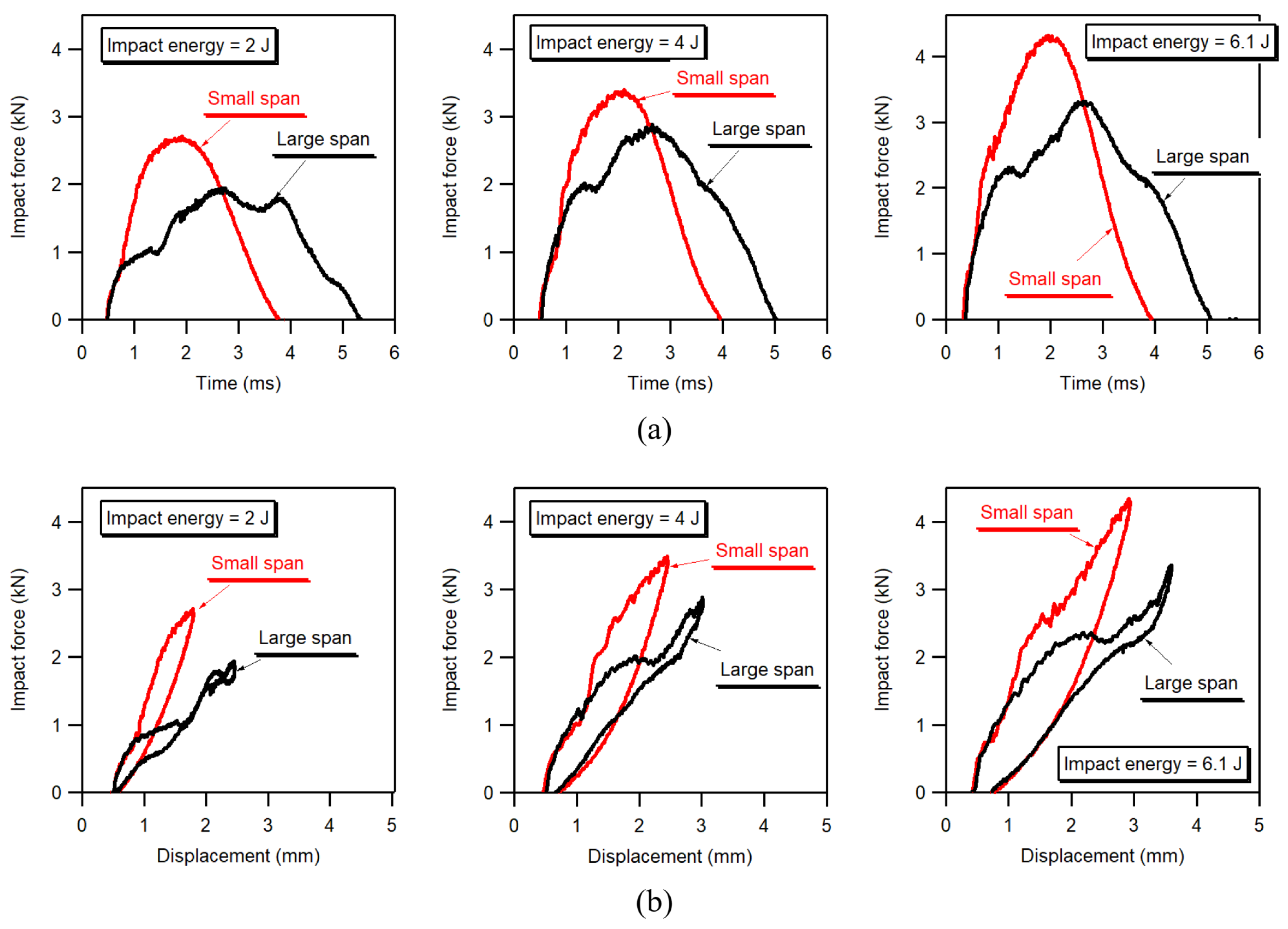
Figure 2 and
Figure 3 show force histories and force–displacement curves for impacts on sandwich panels with low density (HP60;
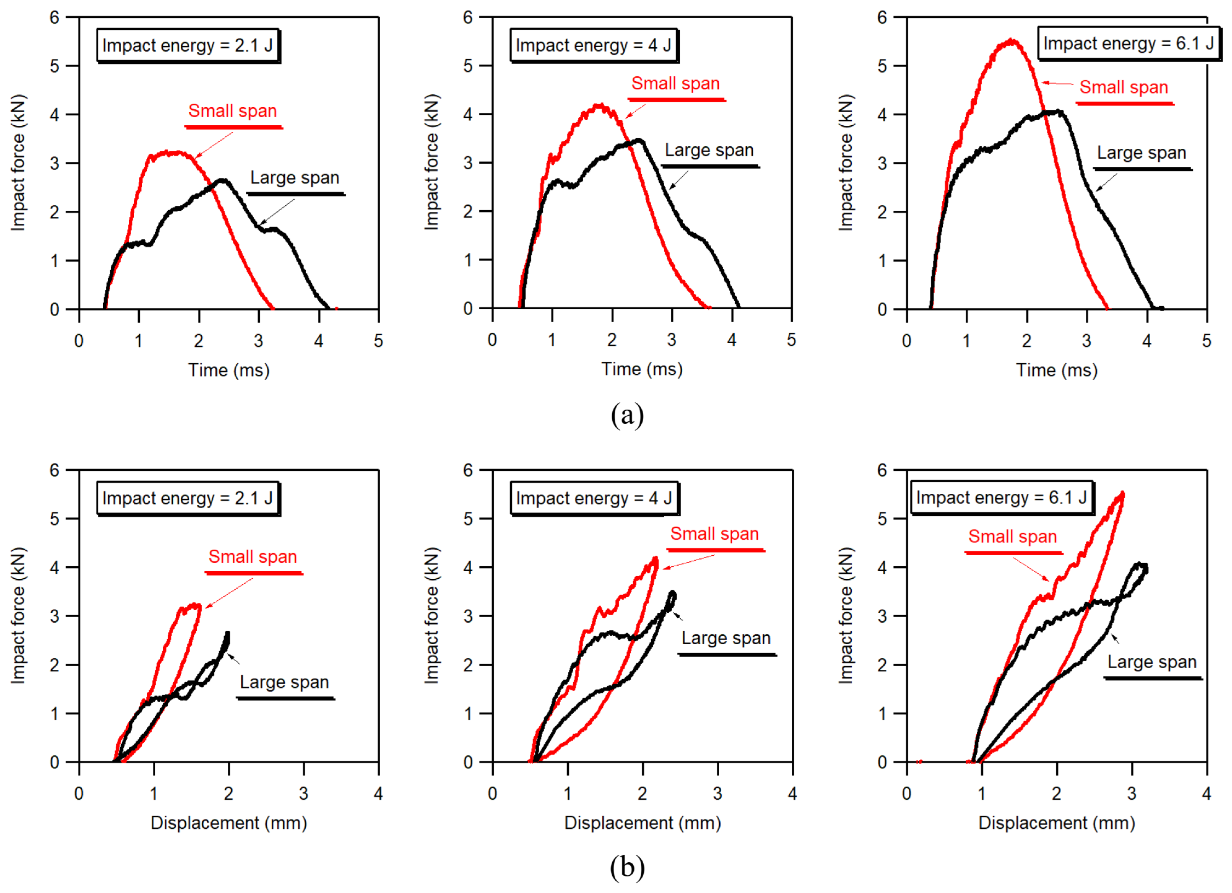
Figure 2) and high density (HP160;
Figure 3) cores. The graphs compare the impact curves of panels positioned on the 45 mm × 67.5 mm window cut-out (small-span configuration) with those of panels supported on the 300 mm span (large-span configuration).
It is immediately seen that, for both HP60 and HP160 sandwich composites, the structural response of panels with a large span is very different to that of panels supported on a small-span window. An evident difference concerns the general shape of the impact curves, which show fluctuating force histories for large-span panels as compared to smoother and more regular force histories for small-span panels. Furthermore, as expected, because of the lower flexural rigidity of large-span panels, impacts on panels supported on the long 300 mm span are characterized by lower peak loads, larger displacements and longer impact durations than small-span counterpart panels. The significant difference in the peak impact forces between large-span and small-span responses can be readily seen in the graphs of
Figure 4, which plot the peak force values as a function of impact energy for HP60 and HP160 panels. It may be worth remarking that, because of the increased support provided by the high density HP160 foam to the impacted skin, HP160 panels exhibit a much stiffer response than corresponding HP60 panels, with higher peak loads, smaller displacements and shorter impact durations, as is easily observed by comparing the graphs of
Figure 2,
Figure 3 and
Figure 4.
A detailed examination of the traces of
Figure 2 and
Figure 3 shows that the force–time and force–displacement curves measured during impact on small-span and large-span panels have the same trend during the initial stage of contact. However, the impact responses start to diverge considerably for larger displacements, when the large-span panels start exhibiting high-amplitude, low-frequency, force oscillations, with global force–displacement slopes significantly lower than those of small-span panels. These results clearly indicate that after the very early contact phase, during which the local indentation response dominates the interaction between the impactor and the panel, the impact behaviour becomes increasingly dependent on the boundary conditions. Therefore, the characteristic shapes of the large-span impact curves are the result of the complex combination of the local elastic and damage response to indentation, the global flexural response of the panel, and the dynamic interaction between the impactor, the target panel and the surfaces of the supporting fixture.
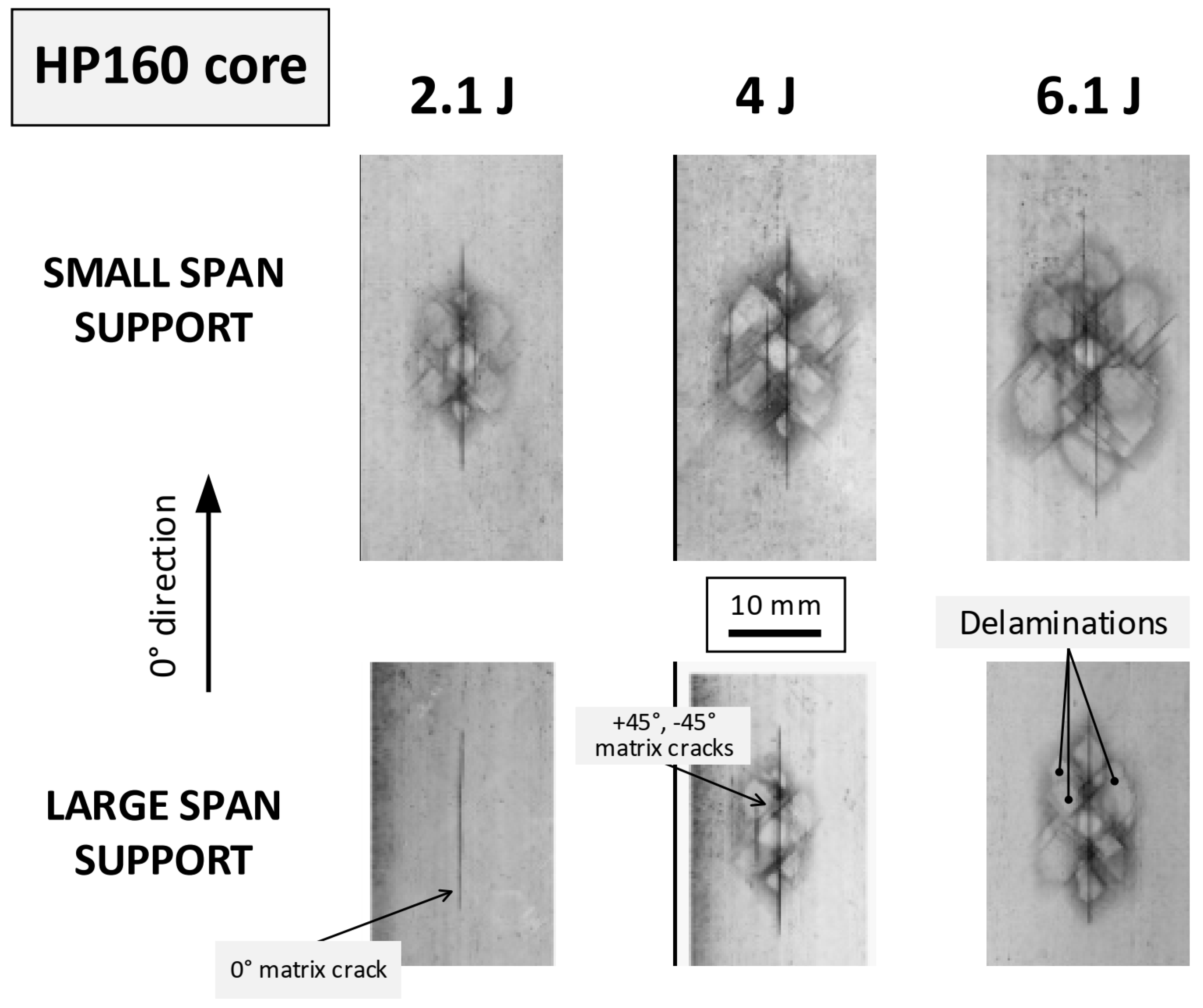
X-radiographs of damage induced by impacts of increasing energies on small-span and large-span lengths are shown in
Figure 5 and
Figure 6, respectively, for HP60 and HP160 foam cores. The sandwich panels exhibit similar impact damage patterns, consisting of a stack of peanut-shaped delaminations that develop at different interfaces of the impacted skin, together with shear and tensile matrix cracks that affect, respectively, the central +45°/−45° plies and the bottom 0° plies. Neither significant fibre fracture nor debonding between the core and the composite skins were observed on the impacted panels for the examined range of impact energies. It is immediately seen that, for the same impact energy, the extent of damage is significantly smaller in large-span panels than in small-span panels for both HP60 and HP160 cores. These results show that the boundary conditions play a critical role not only in controlling the structural response of the sandwich component but also in driving the onset and growth of the damage induced by the impact in the composite skin.
5. Comparison between Numerical and Experimental Results
Experimental and simulated force–time and force–displacement curves for three energy levels are plotted in the graphs of
Figure 8,
Figure 9,
Figure 10 and
Figure 11.
Figure 8 and
Figure 9 compare the numerical and measured responses to impact of panels with HP60 foam core. Analogous comparisons are shown in
Figure 10 and
Figure 11 for panels with HP160 foam core.
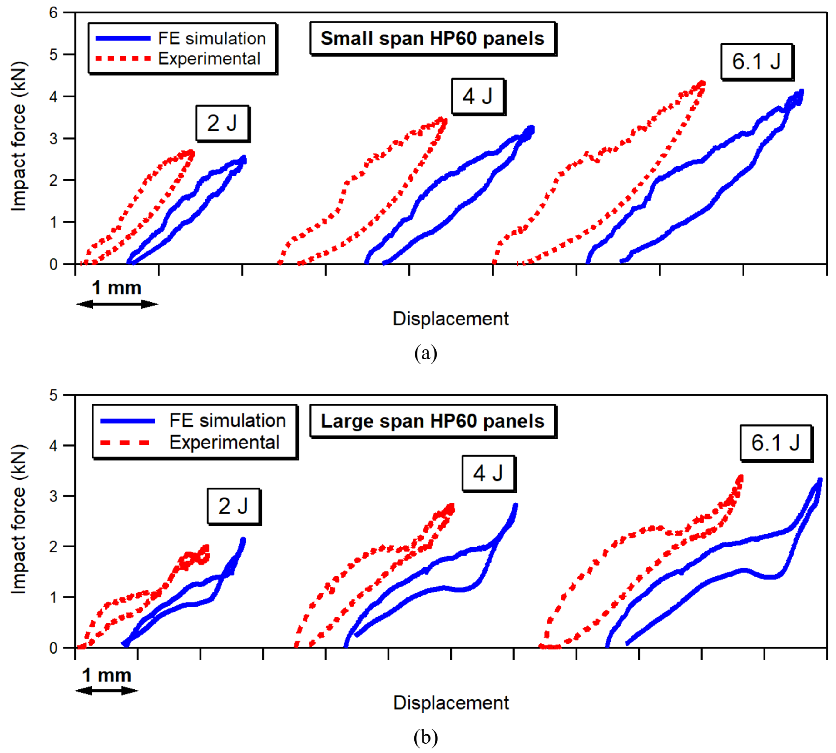
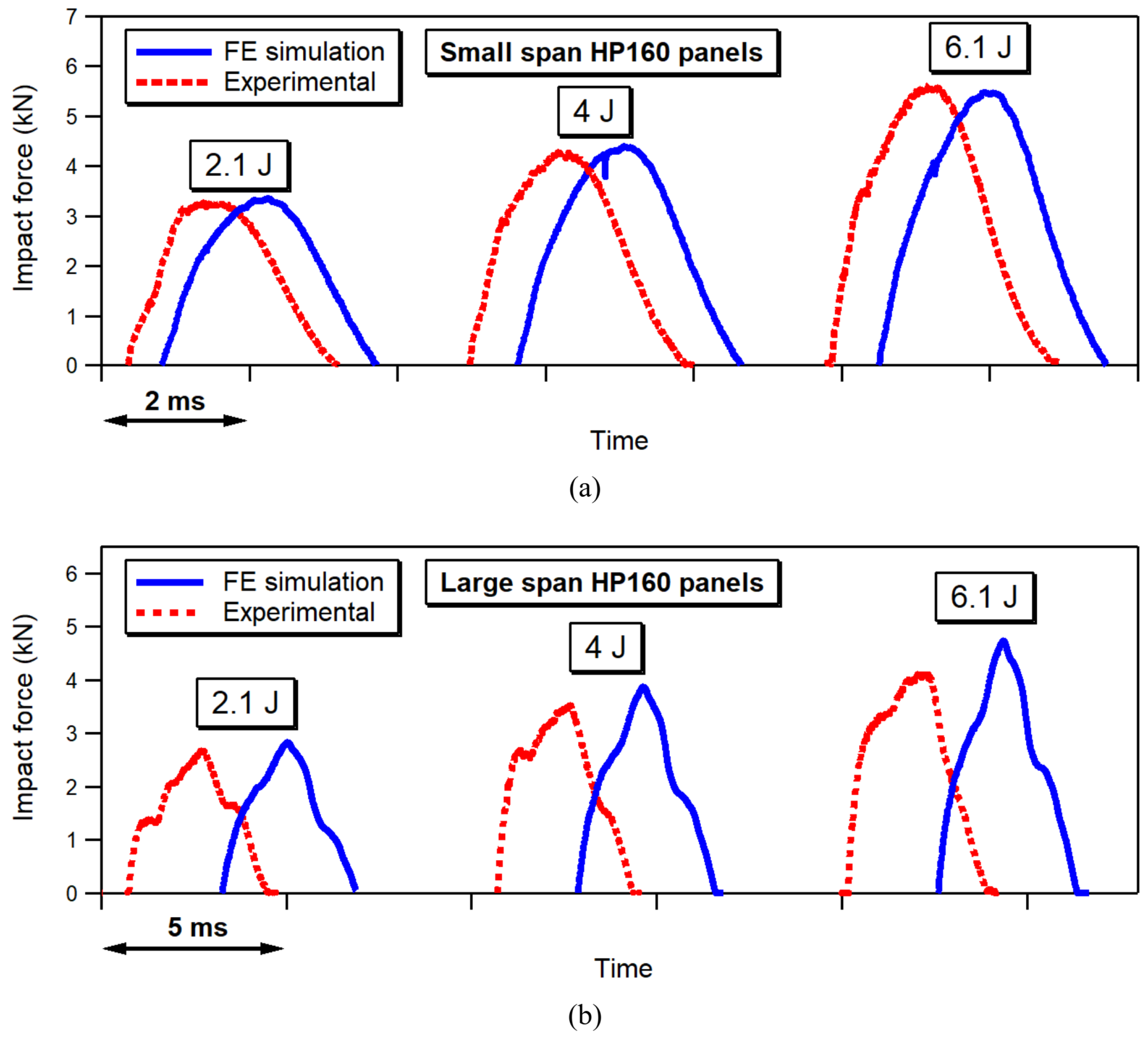
It may be seen that a rather good agreement is achieved in terms of force–time histories and force–displacement curves between FE simulations and experiments for both small-span and large-span boundary conditions. We may notice that the FE model correctly captures the drastic modification of the response of the sandwich plates when the boundary conditions are changed from the small-span to the large-span support. In particular, the graphs of
Figure 8a,
Figure 9a,
Figure 10a and
Figure 11a show that the impact curves obtained when modelling impacts on small-span panels exhibit a rather smooth trend, which is indicative of a structural behaviour essentially controlled by the localized material response at the contact region. On the other hand, the FE simulations of impacts on large-span panels, presented in the graphs of
Figure 8b,
Figure 9b,
Figure 10b and
Figure 11b, show that the model is able to reproduce the peculiar shape of the force–time and force–displacement curves, by correctly replicating the presence of the high-amplitude, low-frequency, force fluctuations due to the dynamic oscillation of the whole panel induced by the impulsive load.
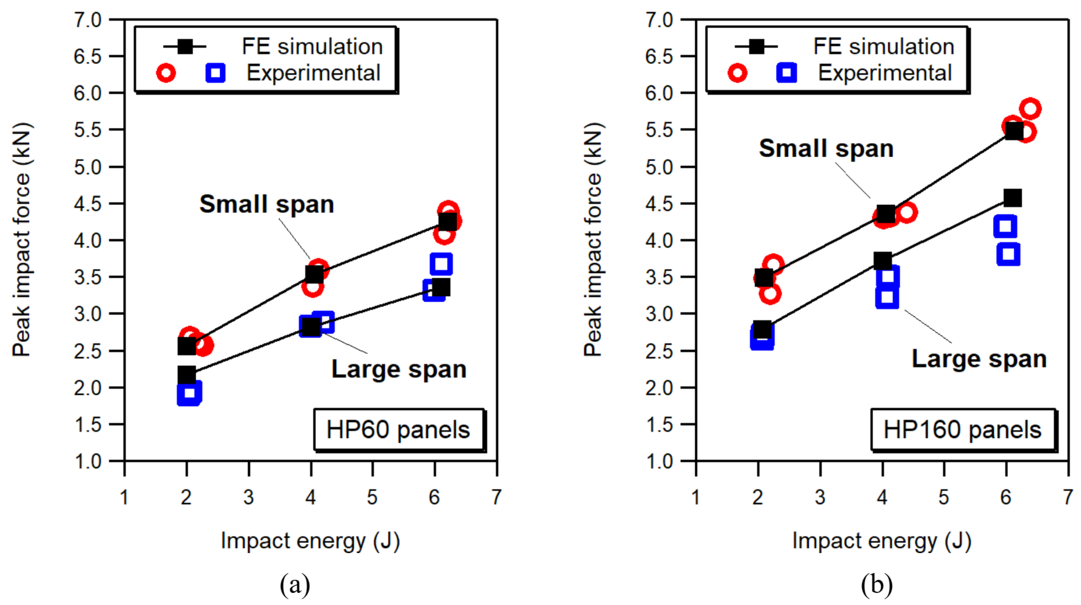
The predictive performance of the model is summarized in terms of peak force in the graphs of
Figure 12, where the maximum forces measured during impact on small-span and large-span panels are plotted as a function of impact energy for HP60 (
Figure 12a) and HP160 (
Figure 12b) sandwich panels. The graphs show that a rather good correlation is achieved between simulated and experimental peak impact forces for the different boundary configurations, foam core densities and impact energies, even though the FE model tends to slightly overestimate the peak forces of large-span HP 160 panels at higher impact energies. It is seen, in particular, that the FE analyses reproduce correctly, for both HP60 and HP160 sandwich composites, the reduction in the peak forces measured on large-span panels as compared to small-span panels, thus confirming the effectiveness of the tool in properly accounting for the global dynamic response to impact of the structure.
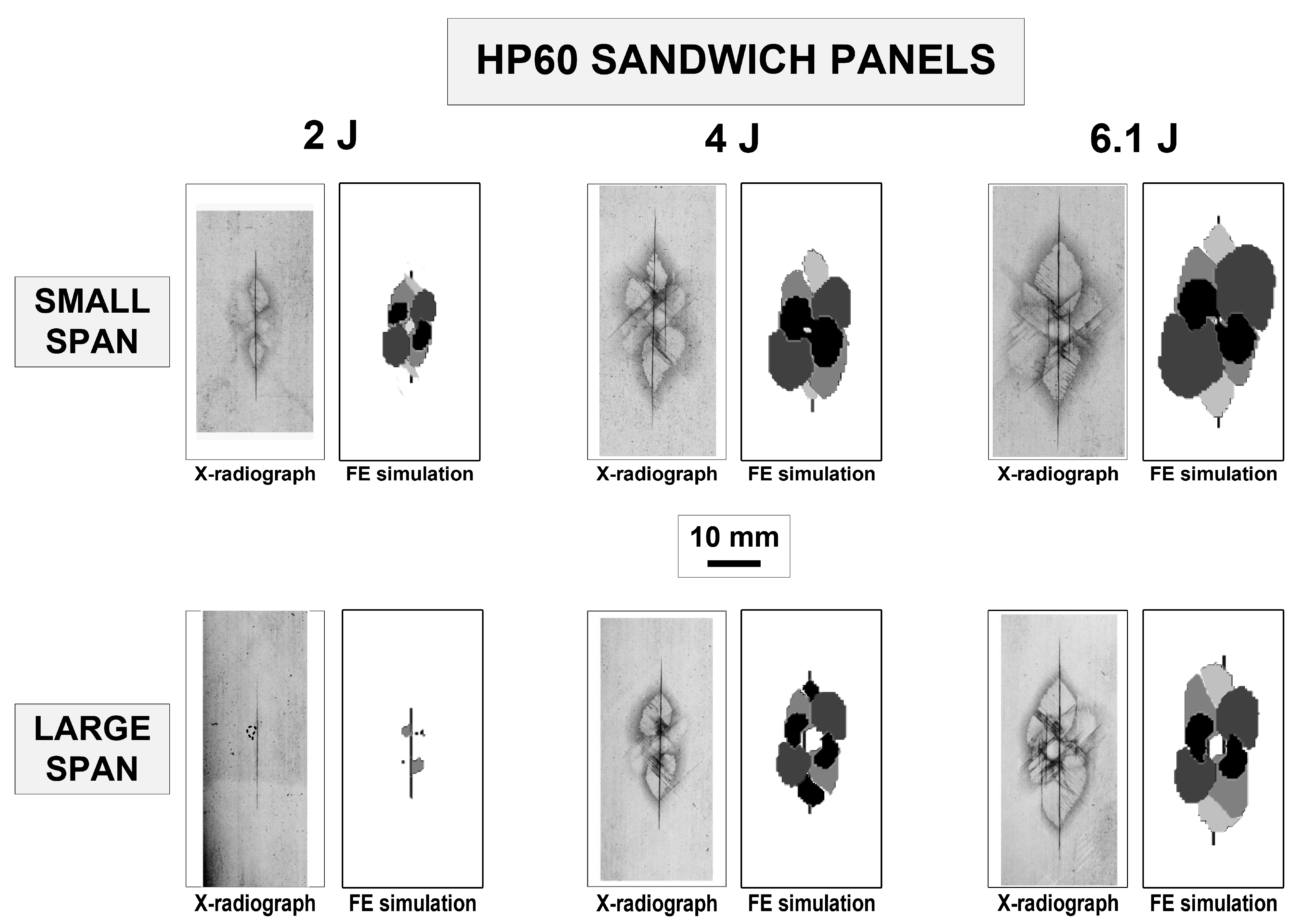
Figure 13 and
Figure 14 compare images of impact damage as revealed by X-radiography with damage maps obtained by the FE analyses, where the different grey levels correspond to different damage depths. We may see that the FE model produces a faithful description of the damage pattern of the HP60 and HP160 sandwich panels for both the small-span and large-span support conditions. The FE simulations provide an adequate prediction not only of the planar size and of the typical shape of the impact damage, but also of the sequence of the different failure mechanisms that occur under increasing impact energy. In agreement with the experimental observations, the FE analyses predicts that damage initiates with a long matrix crack on the bottom 0° plies and small delaminations at the +45°/−45° and −45°/+45° interfaces. With increasing impact energies, delaminations are predicted to develop and grow at the other interfaces, along with some diffuse matrix cracking in 0° and ±45° layers, as indicated in the FE damage maps of
Figure 13 and
Figure 14. The FE tool is also capable of capturing, with remarkable accuracy, the distribution of internal damage at different depths of the impacted skin, as shown in the example of
Figure 15, which presents a three dimensional reconstruction of the individual failure mechanisms predicted by the FE model for a 6.1 J impact on a large-span HP160 sandwich panel.
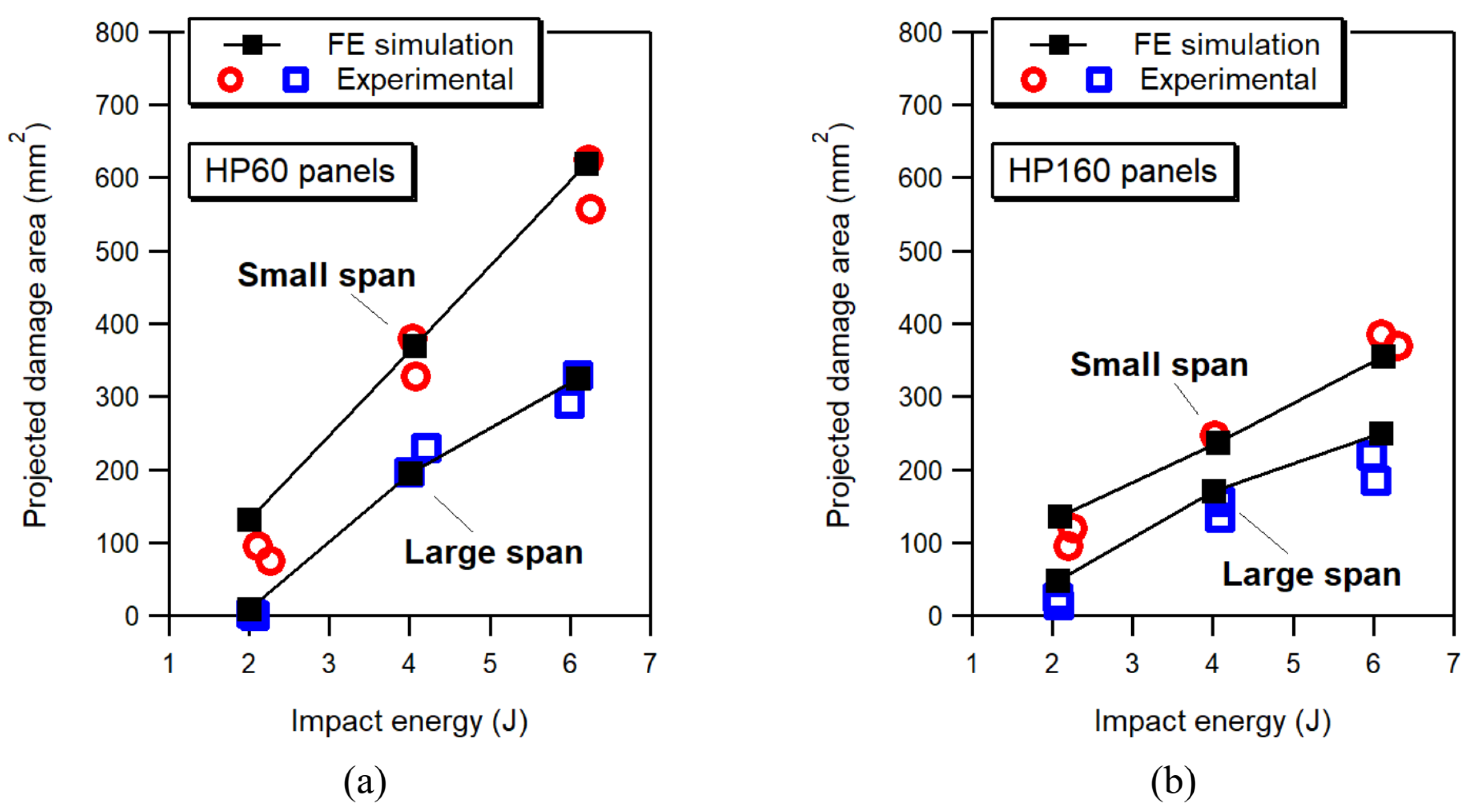
The predictive performance of the FE model in terms of overall damage extent is illustrated in the graphs of
Figure 16, which compare experimental and predicted projected damage areas for small-span and large-span panels. The projected damage areas, defined as the projection onto a single plane of the delaminated areas at all interfaces of the impacted skin, was measured on the radiographic images as the area enclosed by the contour enveloping all delaminations. The data reported in the graphs of
Figure 16 show a remarkably good quantitative match between values of experimental and simulated damage areas, with the proposed FE model successfully capturing the significant difference in damage size observed, for the same impact energy level, between the large and small support configurations.
6. Conclusions
The influence of the boundary conditions on the impact behaviour of sandwich composites was examined in this study at impact energies inducing damage with different BVID severities. Panels with carbon/epoxy skins and low density (HP60) or high density (HP160) PVC foam cores were manufactured for the impact tests. Two different support conditions (a small-span and a large-span configuration) were experimentally investigated. The relevant data collected during the experiments were used to explore the capability of an FE tool to correctly reproduce the structural behaviour of the sandwich composites over the different response scenarios associated with the two boundary conditions.
The experimental observations show that the impact response of large-span panels is significantly different from that of small-span panels. Impact events on large-span panels are characterized by lower peak forces, larger displacements and longer contact durations as compared to those of corresponding small-span panels. Furthermore, the force history measured during impact on large-span panels is strongly perturbed by high amplitude oscillations associated to the overall dynamics of the panel. In contrast, small-span panels exhibit a much smoother force history, which is essentially controlled by the local response of the material at the contact region. The support conditions also greatly affect the damage response of the sandwich composites, with extents of impact damage in large-span panels always notably smaller than those of counterpart small-span panels.
A comparison of the experimental results with the outcomes of the numerical simulations shows that the FE model predicts, with a rather good accuracy, the structural behaviour (in terms of force–time and force–displacement curves) and the damage response (damage size, individual failure mechanisms and three-dimensional pattern) of HP60 and HP160 sandwich panels for both the small-span and the large-span support conditions. The FE tool thus appears capable of simulating correctly, without any model tuning or parameter calibration, the physical mechanisms by which the support conditions affect the impact behaviour of the sandwich panels, thus suggesting the applicability of the proposed numerical approach for modelling the impact response of sandwich structures with scales and boundary conditions typical of real engineering applications. Additional experimental tests and associated FE simulations are however needed to extend the analysis to impacts with energies inducing higher damage severities, such as those involving large-scale fibre fracture or perforation/penetration conditions.


