Article

Uniaxial Compressive Behavior of AA5083/SiC Co-Continuous Ceramic Composite Fabricated by Gas Pressure Infiltration for Armour Applications

by
Achuthamenon Sylajakumari Prasanth
1,
Vijayan Krishnaraj
2,*,
Jayakrishnan Nampoothiri
2,
Ramalingam Sindhumathi
2,
Mohamed Raeez Akthar Sadik
2,
Juan Pablo Escobedo
3 and
Krishna Shankar
3
1
Department of Mechanical Engineering, PSG College of Technology, Coimbatore 641004, Tamilnadu, India
2
Department of Production Engineering, PSG College of Technology, Coimbatore 641004, Tamilnadu, India
3
School of Engineering and Information Technology, The University of New South Wales, Canberra, ACT 2600, Australia
*
Author to whom correspondence should be addressed.
J. Compos. Sci. 2022, 6(2), 36; https://doi.org/10.3390/jcs6020036
Submission received: 31 December 2021 / Revised: 16 January 2022 / Accepted: 17 January 2022 / Published: 20 January 2022
(This article belongs to the Special Issue Manufacturing of Fibrous Composites for Engineering Applications)

Abstract

:
A novel approach of a gas pressure infiltration technique is presented for the synthesis of Co-Continuous Ceramic Composite (C4). SiC foams of varying pore sizes were infiltrated with aluminium AA5083. Optical examination revealed that the SiC foams contained open cells with a network of triangular voids. The number of pores-per-inch (PPI) in the foams was found to depend on the strut thickness and pore diameter. The compressive strengths of two foam configurations, 10 and 20 PPI, were estimated to lie between 1–2 MPa. After infiltration, the compressive yield strength of the resulting C4 was observed to increase to 126 MPa and 120 MPa, respectively, for the 10 and 20 PPI C4. Additionally, the infiltration of ceramic foam with the AA5083 alloy resulted in an increase in strength of 58–100 times when compared with plain ceramic foam. The failure modes of the composites in compression were analyzed by crack propagation and determining the type of failure. The study revealed that shear failure and vertical splitting were the predominant mechanisms of compression failure, and that the fabricated C4 is advantageous in mechanical properties compared to the plain ceramic foam. This study, therefore, suggests the use of C4 composites in armour applications.

1. Introduction

Ballistic protection systems such as armour generally consist of several layers of materials. Each layer performs a specific role in attenuating the energy of projectiles [1,2]. Typically, a hard material such as ceramic is positioned on the front striking face and a matrix composite or high strength steel is placed as the backing face. The front face plate retards the striking force of the projectile by actions such as tumble, erosion, and fracture, whereas the backing material absorbs the residual kinetic energy of the projectile to bring the fragments to rest [3,4]. Ballistic protection plates composed of ceramic sticking face with polymer matrix composite (PMC) back plates have been extensively explored and proven for typical ballistic impact conditions. The abrasion resistance and hardness of the ceramic front face enables it to blunt the approaching projectile and absorb its energy to reduce the impact hazard. However, poor ductility limits its potential to take multiple hits. In addition, the processing complexities, cost, and weight of these systems restrict their wide use. Energy absorption studies in both quasi-static and dynamic conditions have revealed that steel–steel composite metal foams are suitable for armour. However, strict desiderata of lightweight materials for the strategic movement of defence personnel and vehicles restrain the use of such materials [5,6]. Hence, a review of prior studies indicates that weight reduction of ballistic protection plates is paramount in the research of alternative materials for armour.
A study by Chang et al. [6] reported the development of lighter bullet proof material composed of ceramic faced metal–ceramic interpenetrating composites (IPCs). These IPCs exhibited better impact resistance and were less susceptible to abrupt demolition due to the development of stress wave at the interface. The primary reason was attributed to acoustic impedance mismatch between the metal and ceramic. The interlocking type microstructure of the IPCs, also termed as co-continuous ceramic composites (C4), imparts improved fracture toughness, wear resistance, stiffness, and reduced distortions [7,8]. This distinctive combination of enhanced properties of C4 makes it suitable for applications which require high specific modulus, high strength, higher corrosion resistance, and improved abrasion properties, such as brake discs and armour [9,10]. Additionally, these features of C4 can originate new pathways in the design and fabrication of monocoque armour plates exhibiting appreciably less weight with better ballistic protection that may not be attained through a conventional approach. Placing emphasis on weight reduction, which is a requisite for the selection of high specific strength materials in aerospace and armour applications, previous studies have focused on the fabrication of aluminium-based composites by strengthening them with high-strength and rigid particulate ceramics such as B4C, SiC, Si3N4, TiB2 and TiC [10,11]. In C4 composites, the proportion of the ceramic phase can be higher than that of particle-reinforced composites due to their interpenetrated structure. Among the available set of ceramics, SiC is the preferred choice due its mechanical properties, ease of availability, and economic factors. Porous SiC preforms which are interconnected in three dimensions and impregnated with Al alloys, therefore, have the potential for applications in transportation and armour [12,13]. Nong et al. [14] reported the fabrication of 3D SiC/Al co-continuous composite to produce a ventilated shaft disc brake. The wear and friction behaviour of the prepared C4 in this study was comparable to that of cast iron and steel. In addition, better thermal conductivity and better wear resistance were obtained at half the density [15]. Bahrami et al. [16] fabricated bilayer Al/B4C/rice husk ash composites by the pressureless infiltration method. The study revealed that the two factors namely, initial preform porosity and chemical composition of infiltrated alloys, exerted a substantial influence on the electrical resistivity and coefficient of thermal expansion, respectively. Pressureless infiltration was also utilized to fabricate Al/Si3N4 silica composites by Soltani et al. [17]. The results depicted that the processing temperature significantly influenced the modulus of elasticity of the composite. Recent studies by Prasanth et al. [18,19] report that gravity infiltration of SiC co-continuous foam with AA7075 and Al 6063 alloy is effective in enhancing the wear and toughness of the prepared C4 when compared to a monolithic infiltrant material. The compressive strength of such IPCs, produced by squeeze casting, was reported to be 660 MPa. This is higher than that of traditional composites reinforced with SiC particles [20]. Similarly, in another study, infiltration of Ni3Al alloy into porous aluminium oxide by gas pressure infiltration was investigated. Composites with a low volume of Ni3Al showed a fracture strength of 400 MPa. The highest volume fraction of Ni3Al (30 vol.%) displayed a higher fracture strength of 675 MPa [21]. Among the diverse Al alloys, AA5083 is a potential alloy for the regime of C4 composites. Nevertheless, a systematic assessment of AA5083 as an infiltrant material to produce C4 is essential. Though the pressureless infiltration method [22,23] is economical and has the benefits of easy industrialization, pressure infiltration [24,25] is preferred for the manufacture of C4 due to its lower infiltration time, performance, and efficiency. A recent study by Zhang et al. [26] reported that mechanical-pressure infiltration method was effective for producing Al2O3/Al based materials for scaffoldings. The study also reported that the pressure infiltration technique enhanced the interfacial bonding between Al2O3 layers and the infiltrant Al alloy. Though C4 composites have been extensively analyzed for wear applications, studies with an emphasis on their compressive behavior for armour applications are scarce, to the best of the authors’ knowledge.
Therefore, the focus of this investigation is on the synthesis, microstructural characterization, and a detailed analysis of the compressive behavior of AA5083/SiC C4 composites manufactured through the gas pressure infiltration technique. The properties of the constituent ceramic foam were also analyzed and discussed in comparison with the C4.

2. Materials and Methods

The materials utilized to manufacture the C4 composites are delineated in Section 2.1 and Section 2.2 hereunder. The method of infiltration employed to manufacture the C4 is detailed in Section 2.3. Section 2.4 and Section 2.5 describe the analyses of microstructural and mechanical properties respectively, conducted on the SiC foams and the C4 composites.

2.1. Ceramic Foam

In this study, SiC ceramic foams consisting of two different pore sizes, namely 10 and 20 pores per linear inches (ppi), were employed as the reinforcement network. The foams were manufactured by the replica method and commercially sourced from M/s Eltech Ceramics, Tamilnadu, India. Prior to fabrication of the C4, the chemical composition and purity of the SiC foams were characterized by X-ray diffraction (Empyrean Malvern Panalytical, Malvern, UK). Copper K-α X-rays of 1.5406 Å were utilized and the diffractions were collected at a scanning rate of 2°/min. The collected diffractogram was indexed and the peak intensity was used to determine the chemical composition of the SiC foams.

2.2. Infiltrant Alloy

The present study utilizes a commercially sourced AA5083 alloy from Disha Steels, Maharashtra, India in order to infiltrate the pores of the SiC foam to create the C4. The chemical composition of the as-received alloy, shown in Table 1, was analyzed using Optical emission spectroscopy (AMETEK-SPECTROMAXx, Kleve, Germany).

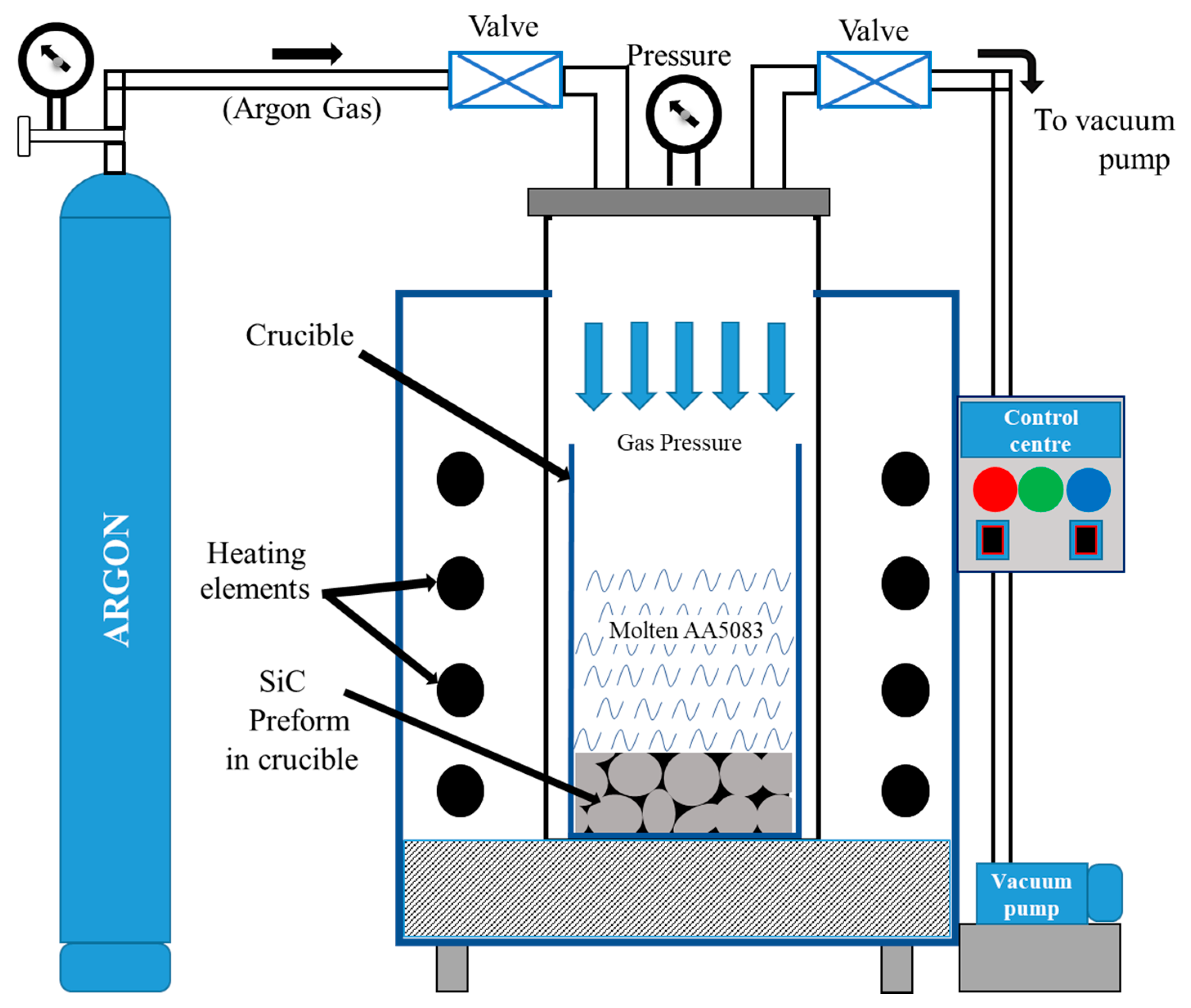
2.3. Manufacturing of C4

In this study, two configurations of C4 were manufactured by low pressure infiltration of AA5083 into the pores of the 10 and 20 ppi SiC foams respectively. A custom-designed Ar gas based set-up, as depicted in Figure 1, was utilized to perform the low pressure infiltration. The set-up comprises a pressure chamber of dimensions Ø100 mm × 450 mm capable of heating to a maximum temperature of 1200 °C and withstanding a maximum pressure of 6 bar. The pressure chamber was designed such that it served as a crucible for the dual purpose of melting and infiltration. The crucible containing SiC foam was preheated to 750 °C and a measured quantity of aluminum AA5083 ingot slices were added for melting. This specific sequence aided in reducing thermal shock exerted on the ceramic foam due to the difference between room temperature and the furnace atmosphere. It further prevented sudden clogging of molten Al during the infiltration process. Subsequently, the melt was superheated to 795 °C to accelerate the kinetics of infiltration. To facilitate pressure infiltration, the atmospheric air present in the chamber was evacuated by a rotary vacuum pump to a level of 10−2 bar. Subsequently, Ar inert gas was purged into the sealed chamber to raise the pressure to 4 bar. The composite melt was maintained in this environment for one hour to ensure complete infiltration. Thereafter, the infiltrated composite was allowed to solidify and cool to 400 °C in the furnace and eventually, by air cooling. The fabricated C4 was then machined out by a series of facing, turning and grinding operations.

2.4. Analyses of Microstructural Properties

Subsequent to manufacturing the C4, the quality of infiltration in both configurations of SiC foam and C4 samples was determined by measuring the porosity levels using Archimedes’ principle. The average porosity of three foam samples for each of the two configurations was determined using Equations (1)–(3).
Porous   Density ,   PD   = Mass   of   porous   foam Volume   of   porous   foam   g / cc
Bulk   Density ,   BD   = Aggregrate   mass   of   SiC   particles   in   the   foam Volume   of   porous   foam   g / cc
Percentage   Porosity ,   PP   = ( 1 PD BD ) × 100
The porous density (PD) of the foam in Equation (1) represents the density encompassing the pores in the foam structure. The bulk density (BD) in Equation (2) was estimated using the actual quantity of SiC particles that constitute the foam. The percentage porosity (PP) in Equation (3) is a measure of the air pores available to be completely filled by AA5083 during the infiltration process. The volume fractions of the ceramic and Al phases in the C4 were estimated by Archimedes’ principle using Equations (4) and (5).
Volume   fraction   of   Al   in   C 4 = Volume   of   Al   in   C 4 Volume   of   C 4
Volume   fraction   of   SiC   in   C 4 = Volume   of   SiC   in   C 4 Volume   of   C 4
Next, microstructural studies were performed on the two SiC foam configurations and the C4 composites thus manufactured. All metallographic samples analyzed in this study, were prepared by standard metallographic sample preparation procedures using a Struers Tegramin-25 grinding and polishing machine. The optical micrographs of un-etched samples were captured using a ZEISS Axio Imager M2m optical microscope (OM).

2.5. Analyses of Mechanical Properties

The mechanical properties of SiC foams and the C4 were assessed through compression tests. A set of three samples each from SiC foams and C4 of dimensions Ø70 mm × 22 mm and Ø13 mm × 25 mm, respectively, were utilized as compression specimens. The compression tests were performed in accordance with ASTM E9 standard using a universal testing machine (Tinius Olsen, Norway) of capacity 50 kN with a cross head velocity of 0.5 mm/min. Subsequently, fractography analysis was performed in order to substantiate the observations from compression tests. The fractured face and the lateral sides of the specimen were examined using an optical microscope (Dino-lite capture) for indications of crack lines, shear failure, and vertical splitting failure of composite.

3. Results and Discussion

3.1. Metallographic Analysis of SiC Foams

The X-Ray diffraction pattern was extracted for the two configurations considered in this study, namely the 10 ppi (F10) and 20 ppi (F20) SiC foams. The identified constituents of the F10 and F20 foams and crystallographic structures along with their Joint Committee on Powder Diffraction Standards (JCPDS) reference patterns are listed in Table 2.
Next, during quantitative phase analysis, a refinement was performed with the High Score Plus 4.8. The results of the quantitative analysis of phase weight fractions and the percentage of each constituent for F10 is shown in Figure 2.
Figure 3 presents the indexed diffraction pattern for F20 along with the identified phases. All major peaks were assigned to the dominant phases, namely SiC and Al2O3. In addition, small peaks corresponding to CaCO3 and SiO2 were also identified. The compositional details of each compound are listed in Figure 3.
The peak intensities of F10 and F20 as depicted in Figure 2 and Figure 3 were used to calculate the weight fraction of each phase in a mixture and are tabulated in Table 3. The X-ray diffractograms confirmed that SiC was the major constituent of both the foams. In addition, compounds such as Al2O3, CaCO3, Mg and SiO2 were also observed.
It can be inferred from Table 3 that the SiC content of F20 is higher than that of F10. It is well known that the ceramic phase, namely SiC, is brittle in nature. This can potentially lead to crack initiation and brittle fracture in the ceramic phase when subjected to compression [27].

3.2. Porosity and Structural Analysis of SiC Foams

The porosity of the foams was estimated using Equations (1)–(3) and is tabulated in Table 4. It can be inferred from Table 4 that the BD and PP of F20 is less than that of F10. This suggests a variation in the morphology of SiC struts between the two foam configurations. Therefore, a detailed study of the morphology of the two foam structures was conducted.
Figure 4a–d represents the morphologies of the F10 and F20 SiC foams respectively. The strut thickness and pore diameters of both foams are tabulated in Table 5.
It can be inferred from Table 5 that the strut thickness and pore diameter of F20 is less than that of F10. Figure 4b reveals that F20 is highly interconnected when compared with F10. This signifies that a foam with lower strut thickness and pore diameter will possess a highly interconnected network of SiC. Additionally, it can be deciphered from Table 5 that the pore diameter decreases with an increase in the ppi of the foam.
In addition to the pore diameter and strut thickness, the strength of struts is a crucial factor influencing the mechanical strength of the foam. The SiC foams considered in this study consisted of an open-cell structure with a network of voids. These foams, as shown in the insets of Figure 4a,b, are termed as reticulated ceramics [28]. The extreme porosity, interconnected void volume, adjacent pores and their light weight make reticulated SiC ceramic foams ideal for the infiltration of molten metal [29]. As evident from Figure 4c,d, these porous structures possess hollow triangular voids that led to a reduction in their mass. Investigation of the strut structure of the F10 and F20 foams revealed that the estimated average side length of the triangular voids was ~466 µm and ~377µm, respectively.

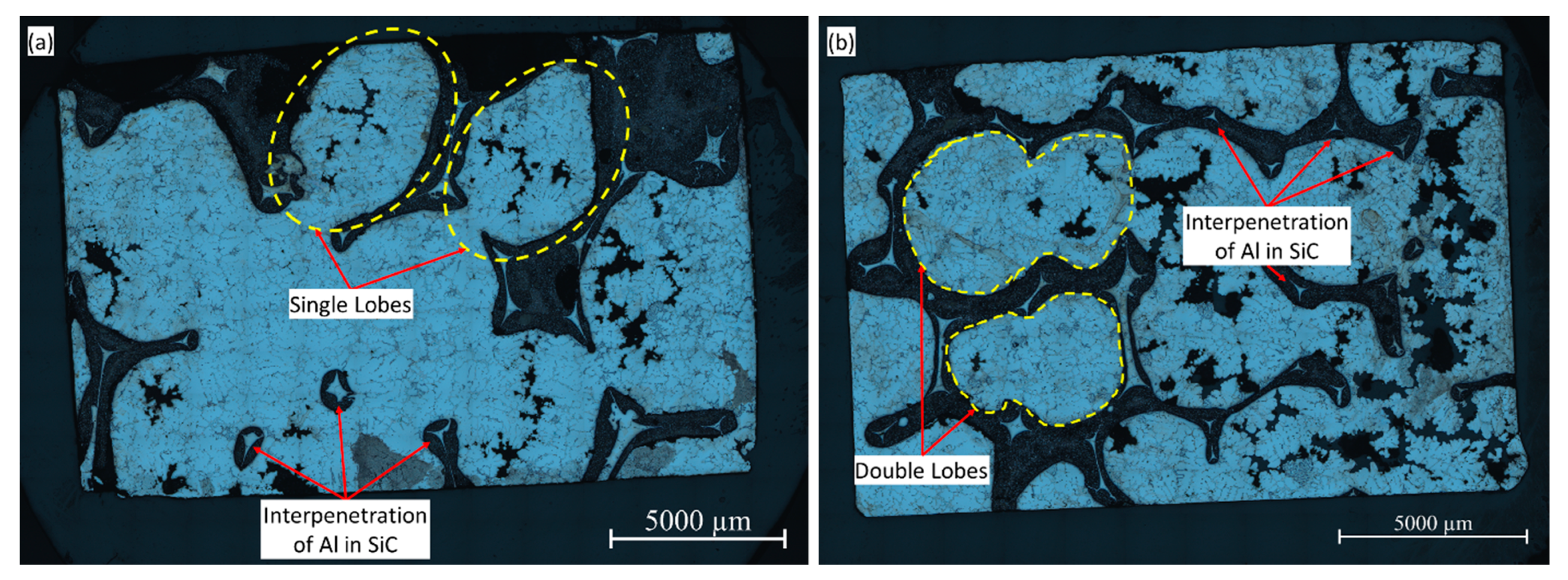
3.3. Microstructural Analysis of C4

The optical micrographs of the as-cast C4 samples comprising the F10 and F20 foams infiltrated with AA5083 are shown in Figure 5. The ability to bear the compressive load exerted on the composite substantially depends on the morphology of the foam and infiltrant Al [20]. It can be observed that both infiltrated composites exhibit a spherical morphology. In particular, the C4-F10 exhibited a single lobe structure when compared with C4-F20 which reveals a double lobe structure. This distinction can be attributed to the small pore size of the F20 as detailed in Section 3.2. During formation of the composite, the molten Al impregnates and fills the pores of the foam, resulting in the characteristic lobe structures of the F10 and F20 foams. These distinctive morphologies, namely the lobe structures, have a salient effect on the compressive load-bearing capacity of the resulting C4 composite. Figure 5 also depicts through interpenetration of the Al alloy inside the voids of both SiC foams. The volume fractions estimated using Equations (4) and (5) are listed in Table 6. The table denotes that both configurations of C4 have approximately 80% by volume of AA5083 infiltrated into the SiC foams.

3.4. Mechanical Property Analysis

As delineated in Section 2.5, the assessment of mechanical properties was performed by conducting compression tests on the two foam configurations, namely F10 and F20, and on the manufactured co-continuous composites, namely C4-F10 and C4-F20. The quasi-static stress-strain response of the SiC foams and three samples each of the C4 composites are depicted in Figure 6. The inferences of the salient outcomes from the compression tests are tabulated in Table 7.
In the displacement curves in Figure 6, the strength of the C4 and SiC foam are marked on the primary and secondary Y axis respectively. From Table 7, the yield strength of F10 and F20 are observed to be ~1 MPa and ~1.3 MPa, respectively. In comparison, the displacement curves of the C4 show that the infiltration of AA5083 melt into the pores of SiC imparts an enhancement in yield strength with values of ~74.3 MPa and ~71.6 MPa for C4-F10 and C4-F20 samples, respectively. As can be deciphered from Table 7, the compressive strength of the SiC foam for the 10 and 20 PPI configuration was ~1.22 MPa and ~2.05 MPa. In contrast, the compressive strength of the C4-F10 composites was ~126 MPa and that of the C4-F20 configuration was ~120 MPa. It can be inferred that the compressive strength of 10 PPI SiC foam was enhanced by about 100 times by infiltrating with ~81 vol.% of AA5083 alloy. In comparison, the compressive strength of the 20 PPI SiC foam improved by close to 58 times when infiltrating with ~77 vol.% of AA5083 alloy.
Table 7 also lists the energy absorbed (EA) per unit volume by the foam and the C4 during compression tests. It was observed that the EA of SiC foam was estimated to be ~1.07 J/mm3 and ~1.68 J/mm3 for 10 PPI and 20 PPI foams respectively. The infiltration of SiC foams with AA5083 enhances the energy absorbed per volume of the C4 samples in both 10 and 20 PPI configurations to ~14.17 and ~13.39 J/mm3, respectively. In addition to the strength and EA, the infiltration of AA5083 alloy remarkably enhanced the elastic modulus from ~0.96 and ~2.3 MPa for the foams to ~2.67 and ~2.69 GPa for the equivalent C4 composites as observed from Table 7. Therefore, it is evident that the infiltration of AA5083 into SiC ceramic foam simultaneously enhances the strength, elastic modulus and toughness, quantified by EA, of the resulting C4.
A salient inference from Table 6 is that the volume fraction of AA5083 in both 10 and 20 PPI composites are nearly the same. However, the compressive strength and EA of the composite is higher in case of the C4-F10 when compared with C4-F20, indicating that the compressive strength depends on the characteristics of the foam. The foam characteristics include PPI, pore diameter and strut thickness.

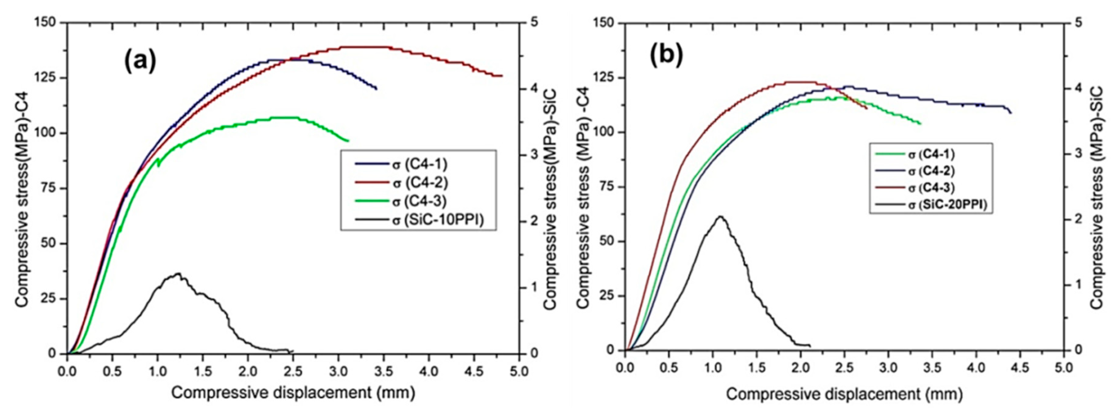
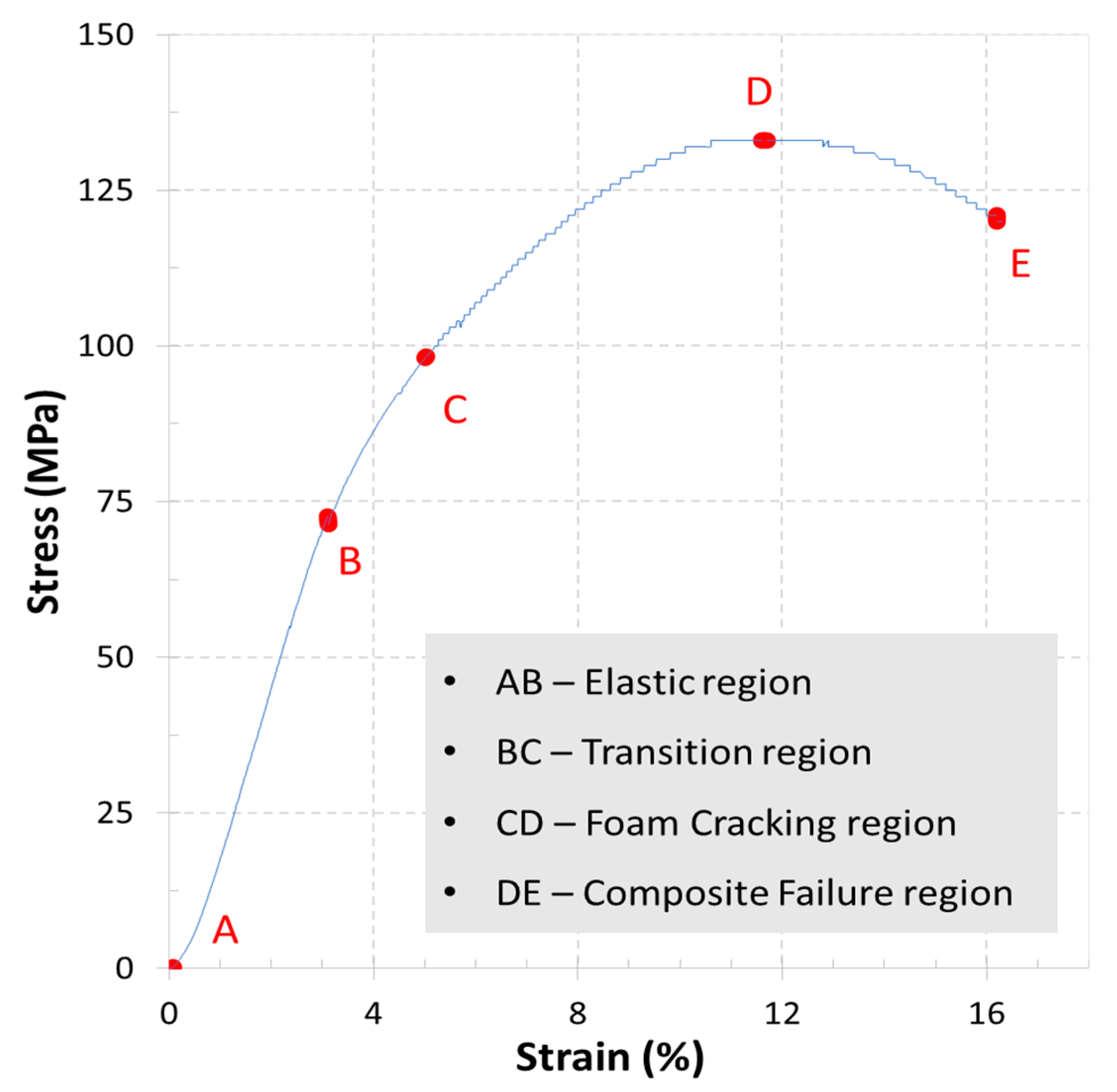
3.5. Compressive Behavior of C4

In order to comprehend the behaviour of the C4 when subjected to compression, a typical stress–strain curve obtained for the C4-F10 is shown in Figure 7. The curve can be segregated into four regions. The smooth line in region AB represents the elastic zone of the composite, during which no cracks were observed. Region BC represents the transition from elastic to failure zone. This was characterized by a minor bend in the curve with a reduced slope when compared to region AB. No cracks or strut failures occurred in the region AC. Subsequently, when the C4 traverses the transition region of BC, failure initiates after point C. It was observed during compression tests that the failure of the composite initiated within the foam was due to its brittle nature. The saw-tooth pattern in region CD was therefore attributed to the progressive cracking of the SiC struts. This was characterized by a cracking noise during testing. In this region CD, the AA5083 in the composite bears the load until point D. Finally, in region DE, the saw- tooth pattern was found to occur due to the splitting of the SiC-Al interface of the C4.

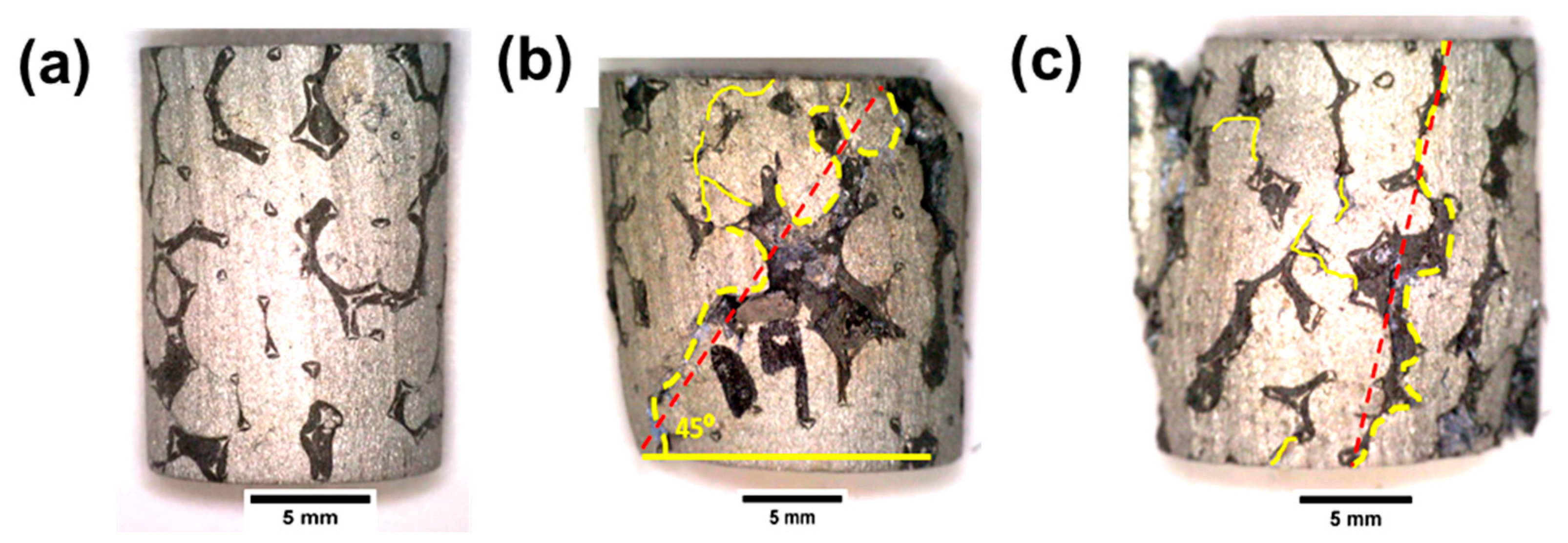
3.6. Fractography Analysis

Analysis of the fractured surfaces, referred to as fractography, is essential to reveal the genesis and mechanism of failure [30]. Figure 8a shows the macroscopic image of the specimen of C4 before application of the uniaxial compressive load. It is evident from the figure that the AA5083 (bright phase) has infiltrated the pores of the SiC foam (dark phase) to form the C4. During compression tests, it was observed that, cracks first initiate at the SiC foam and then propagate to the ductile Al phase as evident from Figure 8b. Since both the C4-F10 and C4-F20 comprise approximately 80% of ductile Al and 20% of brittle SiC foam in a bulk form, it is expected to follow the ‘shear failure’ mode, characteristic of a ductile material. However, as evidenced from Figure 8b, the crack lines deviate from the theoretical line due to disruptions caused by SiC struts. Minor cracks of low intensity were observed to be formed and to propagate for short distances within the specimen. Although the ‘shear failure’ was expected, other types of failure such as ‘Vertical splitting’ were found to occur. Vertical splitting refers to failure along the direction in which the compressive load is applied [31]. This resulted in major cracks originating and propagating along the SiC struts, as deciphered from Figure 8c. The study of the fracture surfaces thus revealed that, the failure of C4 composites is contingent on the profile and orientation of the SiC struts. Hence, it can be proposed that, cracks initiate in the region of weak cell-walls of the foam structure. Subsequently, the cracks propagated to the surrounding cell-walls and plateau junctions. This correlates well with prior observations reported in literature [32,33,34].

3.7. Microstructure of Post-Test C4 Composite

Figure 9a,b exhibit the optical microstructure of the C4-F10 and C4-F20 respectively after compression tests. The microstructure reveals multiple cracks of varied sizes on the SiC struts in both configurations of the C4. In contrast, limited cracks are observed in the AA5083 matrix of C4 composite. This suggests that the quality of interfacial bonding between the Al matrix and foam structure is a paramount factor governing the compressive behavior of C4 composites. The phenomenon of shear failure and vertical splitting discussed in Section 3.6 is also evident from the micrographs.

4. Conclusions

Two configurations of C4 composites composed of 81% and 77% by volume of AA5083 infiltrated into SiC ceramic foam of 10 and 20 PPI respectively, were synthesized using gas pressure infiltration technique. The foams and C4 were subjected to compression tests. The following conclusions were drawn from the study.
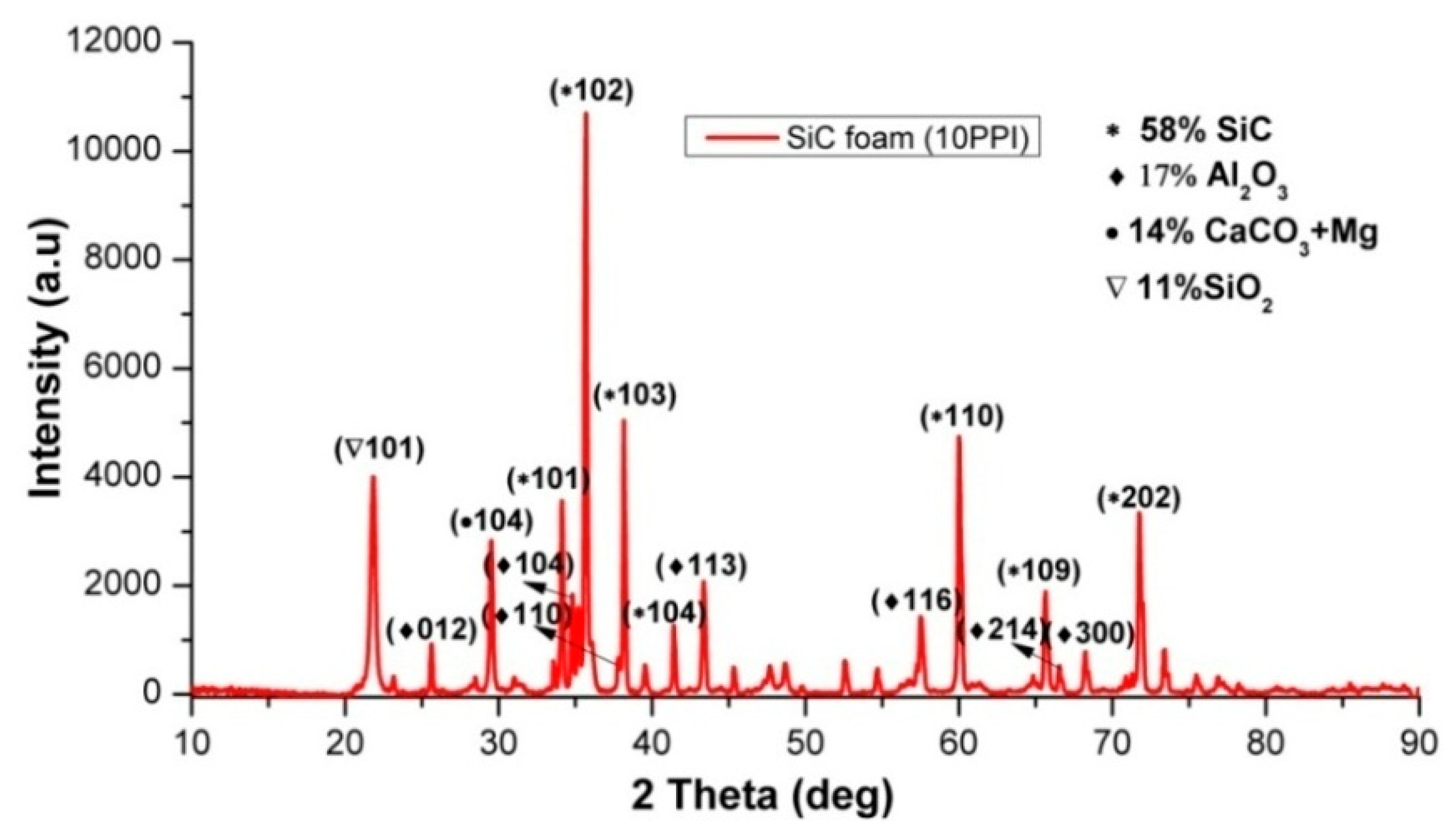
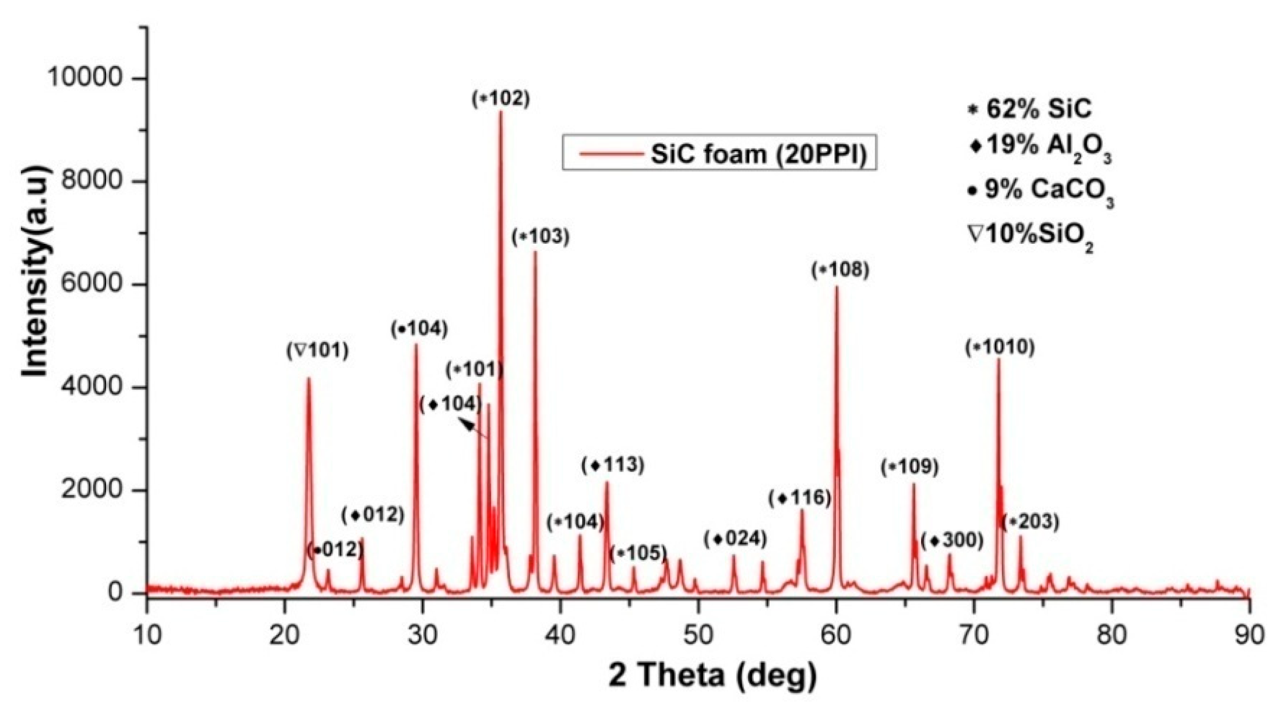
  • The XRD analysis for SiC foams (F10 and F20) revealed the presence of SiC, Al2O3, CaCO3 and SiO2. Additionally, F20 was found to possess higher amounts of brittle SiC when compared to F10.
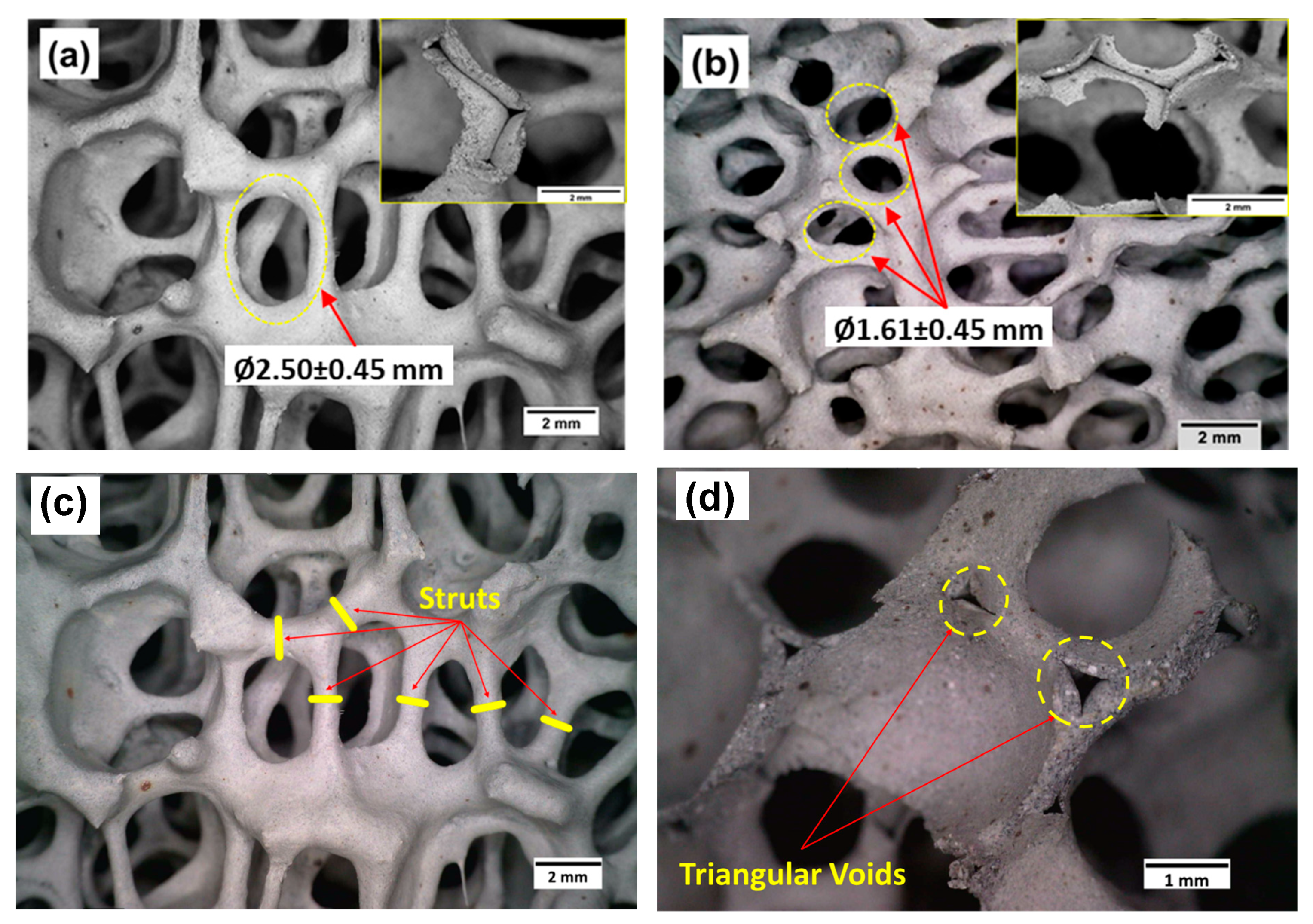
  • The study of porosities indicated that the BD and PP of F20 was lower than that of F10. Extensive study of the morphology of the two foam structures revealed that the strut thickness and pore diameter of F20 is lower than that of F10. Additionally, F20 was observed to possess highly interconnected SiC strut structures when compared to F10.
  • The microstructure of the as-cast composite samples revealed single lobe and double lobe spherical structures for the C4-F10 and C4-F20, respectively. These characteristic lobe structures contribute to the compressive load bearing capacity of the composites.
  • The inference from compression tests was that, overall, the C4-F10 exhibited a better compressive strength of 126 MPa, a significant increase of nearly 100 times, when compared with the bare foam. This indicates that the characteristics of the chosen foam such as strut thickness, pore diameter, and the network of triangular voids is a crucial factor influencing the compressive strength of the C4.
  • The study also revealed that, infiltration of SiC foams with AA5083 enhanced the energy absorbed, strength and elastic modulus of the C4.
  • Fractography analysis revealed that cracks initiate in the frame of the C4 namely, the SiC foam structure. The AA5083 matrix delays the propagation of the cracks and thereby the premature failure of such composites.
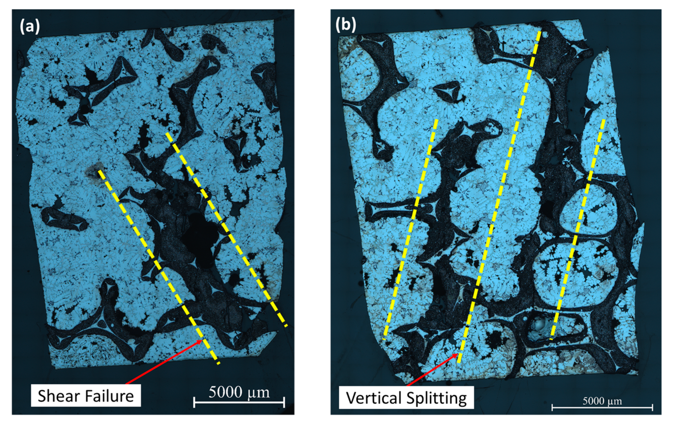
  • Analysis of the compressive failure specimens indicated that the composites followed shear and vertical splitting failure modes. The orientation of the SiC struts was observed to be crucial in preventing crack propagation.

Author Contributions

Conceptualization, A.S.P., V.K., J.P.E. and K.S.; methodology, A.S.P., J.N., J.P.E. and K.S.; validation, J.N., J.P.E. and K.S.; formal analysis, R.S. and M.R.A.S.; investigation, J.N.; resources, A.S.P., V.K. and J.N.; data curation, R.S. and M.R.A.S.; writing—original draft preparation, R.S. and M.R.A.S.; writing—review and editing, A.S.P. and J.N.; visualization, V.K. and M.R.A.S.; supervision, V.K., J.P.E. and K.S.; project administration, V.K.; funding acquisition, A.S.P., V.K., J.P.E. and K.S. All authors have read and agreed to the published version of the manuscript.

Funding

This research was funded by The Scheme for Promotion of Academic and Research Collaboration (SPARC), MHRD, India. Project code: P207.

Institutional Review Board Statement

Not applicable.

Informed Consent Statement

Not applicable.

Conflicts of Interest

The authors declare no conflict of interest.

References

  1. Garcia-Avila, M.; Portanova, M.; Rabiei, A. Ballistic performance of a composite metal foam-ceramic armor system. Procedia Mater. Sci. 2014, 4, 151–156. [Google Scholar] [CrossRef] [Green Version]
  2. David, N.V.; Gao, X.-L.; Zheng, J.Q. Ballistic resistant body armor: Contemporary and prospective materials and related protection mechanisms. Appl. Mech. Rev. 2009, 62, 50802. [Google Scholar] [CrossRef]
  3. Medvedovski, E. Ballistic performance of armour ceramics: Influence of design and structure. Part 1. Ceram. Int. 2010, 36, 2103–2115. [Google Scholar] [CrossRef]
  4. Chabera, P.; Boczkowska, A.; Morka, A.; Kędzierski, P.; Niezgoda, T.; Oziębło, A.; Witek, A. Comparison of numerical and experimental study of armour system based on alumina and silicon carbide ceramics. Bull. Polish Acad. Sci. Tech. Sci. 2015, 63, 363–367. [Google Scholar] [CrossRef] [Green Version]
  5. Jerz, J.; Simancik, F.; Bortel, M.; Kubo, S.; Kovacik, J.; Banhart, J.; Fleck, N.A. The design of lightweight armour sheets. Banhart J. Fleck NA Mortensen A. Cell. Met. Manuf. Prop. Appl. MIT-Verlag 2003, 2003, 43–46. [Google Scholar]
  6. Chang, H.; Binner, J.; Higginson, R.; Myers, P.; Webb, P.; King, G. Preparation and characterisation of ceramic-faced metal-ceramic interpenetrating composites for impact applications. J. Mater. Sci. 2011, 46, 5237–5244. [Google Scholar] [CrossRef]
  7. Travitzky, N.A.; Shlayen, A. Microstructure and mechanical properties of Al2O3/Cu–O composites fabricated by pressureless infiltration technique. Mater. Sci. Eng. A 1998, 244, 154–160. [Google Scholar] [CrossRef]
  8. Chang, H.; Higginson, R.; Binner, J. Microstructure and property characterisation of 3-3 Al (Mg)/Al2O3 interpenetrating composites produced by a pressureless infiltration technique. J. Mater. Sci. 2010, 45, 662–668. [Google Scholar] [CrossRef]
  9. Lu, Y.; Yang, J.; Lu, W.; Liu, R.; Qiao, G.; Bao, C. The mechanical properties of co-continuous Si3N4/Al composites manufactured by squeeze casting. Mater. Sci. Eng. A 2010, 527, 6289–6299. [Google Scholar] [CrossRef]
  10. Jimoh, A.; Sigalas, I.; Hermann, M. In Situ Synthesis of Titanium Matrix Composite (Ti-TiB-TiC) through Sintering of TiH2-B4C. Mater. Sci. Appl. 2012, 3, 30–35. [Google Scholar] [CrossRef] [Green Version]
  11. Meti, V.K.V.; Shirur, S.; Nampoothiri, J.; Ravi, K.R.; Siddhalingeshwar, I.G. Synthesis, Characterization and Mechanical Properties of AA7075 Based MMCs Reinforced with TiB2Particles Processed Through Ultrasound Assisted In-Situ Casting Technique. Trans. Indian Inst. Met. 2018, 71, 841–848. [Google Scholar] [CrossRef]
  12. Daehn, G.S.; Breslin, M.C. Co-continuous composite materials for friction and braking applications. JOM 2006, 58, 87–91. [Google Scholar] [CrossRef]
  13. Jiang, L.; Jiang, Y.L.; Yu, L.; Su, N.; Ding, Y.D. Experimental study and numerical analysis on dry friction and wear performance of co-continuous SiC/Fe-40Cr against SiC/2618 Al alloy composites. Trans. Nonferrous Met. Soc. China 2012, 22, 2913–2924. [Google Scholar] [CrossRef]
  14. Nong, X.D.; Jiang, Y.L.; Fang, M.; Yu, L.; Liu, C.Y. Numerical analysis of novel SiC 3D/Al alloy co-continuous composites ventilated brake disc. Int. J. Heat Mass Transf. 2017, 108, 1374–1382. [Google Scholar] [CrossRef]
  15. Maleque, M.A.; Dyuti, S.; Rahman, M.M. Material Selection Method in Design of Automotive Brake Disc. Proc. World Congr. Eng. 2010, III, 5. [Google Scholar]
  16. Bahrami, A.; Soltani, N.; Pech-Canul, M.I.; Soltani, S.; González, L.A.; Gutiérrez, C.A.; Tapp, J.; Möller, A.; Gurlo, A. Bilayer graded Al/B4C/rice husk ash composite: Wettability behavior, thermo-mechanical, and electrical properties. J. Compos. Mater. 2018, 52, 3745–3758. [Google Scholar] [CrossRef]
  17. Soltani, N.; Soltani, S.; Bahrami, A.; Pech-Canul, M.I.; Gonzalez, L.A.; Möller, A.; Tapp, J.; Gurlo, A. Electrical and thermomechanical properties of CVI- Si3N4porous rice husk ash infiltrated by Al-Mg-Si alloys. J. Alloys Compd. 2017, 696, 856–868. [Google Scholar] [CrossRef]
  18. Achuthamenon Sylajakumari, P.; Ramakrishnasamy, R.; Palaniappan, G. Taguchi Grey Relational Analysis for Multi-Response Optimization of Wear in Co-Continuous Composite. Materials 2018, 11, 1743. [Google Scholar] [CrossRef] [PubMed] [Green Version]
  19. Achuthamenon Sylajakumari, P.; Ramakrishnasamy, R.; Palaniappan, G.; Murugan, R. Multi-response Optimization of End Milling Parameters for Al-Zn-Mg/SiC Co-continuous Composite Using Response Surface Methodology. Medziagotyra 2019, 25, 471–477. [Google Scholar] [CrossRef] [Green Version]
  20. Zhao, L.-Z.; Zhao, M.-J.; Hong, Y.A.N.; Cao, X.-M.; Zhang, J.-S. Mechanical behavior of SiC foam-SiC particles/Al hybrid composites. Trans. Nonferrous Met. Soc. China 2009, 19, s547–s551. [Google Scholar] [CrossRef]
  21. Skirl, S.; Krause, R.; Wiederhorn, S.M.; Rodel, J. Processing and mechanical properties of Al2O3/Ni3Al composites with interpenetrating network microstructure. J. Am. Ceram. Soc. 2001, 84, 2034–2040. [Google Scholar] [CrossRef]
  22. Bahrami, A.; Pech-Canul, M.I.; Soltani, N.; Gutiérrez, C.A.; Kamm, P.H.; Gurlo, A. Tailoring microstructure and properties of bilayer-graded Al/B4C/MgAl2O4composites by single-stage pressureless infiltration. J. Alloys Compd. 2017, 694, 408–418. [Google Scholar] [CrossRef]
  23. Bahrami, A.; Pech-Canul, M.I.; Gutierrez, C.A.; Soltani, N. Effect of rice-husk ash on properties of laminated and functionally graded Al/SiC composites by one-step pressureless infiltration. J. Alloys Compd. 2015, 644, 256–266. [Google Scholar] [CrossRef]
  24. Xiao, Q.; Jiang, G. Effect of Powder Composition on the Preparation of SiC foam/Al Co-continuous Phase Composites by In-situ Reactive Pressureless Infiltration. IOP Conf. Ser. Earth Environ. Sci. 2021, 714, 032014. [Google Scholar] [CrossRef]
  25. Vijayan, K.; Ramalingam, S.; Raeez Akthar Sadik, M.; Prasanth, A.S.; Nampoothiri, J.; Pablo Escobedo-Diaz, J.; Shankar, K. Fabrication of Co-Continuous ceramic composite (C4) through gas pressure infiltration technique. In Proceedings of the Materials Today: Proceedings; Elsevier Ltd.: Amsterdam, The Netherlands, 2021; Volume 46, pp. 1013–1016. [Google Scholar]
  26. Zhang, Q.; Dong, S.; Ma, S.; Hou, X.; Yang, W.; Zhang, Y.; Wu, G. Microstructure and compressive behavior of lamellar Al2O3p/Al composite prepared by freeze-drying and mechanical-pressure infiltration method. Sci. Eng. Compos. Mater. 2020, 27, 1–9. [Google Scholar] [CrossRef]
  27. Li, G.; Zhang, X.; Fan, Q.; Wang, L.; Zhang, H.; Wang, F.; Wang, Y. Simulation of damage and failure processes of interpenetrating SiC/Al composites subjected to dynamic compressive loading. Acta Mater. 2014, 78, 190–202. [Google Scholar] [CrossRef]
  28. Steinacher, M.; Žužek, B.; Jenko, D.; Mrvar, P.; Zupanič, F. Manufacturing and properties of a magnesium interpenetrating phase composite. Stroj. Vestn. J. Mech. Eng. 2016, 62, 79–85. [Google Scholar] [CrossRef] [Green Version]
  29. Islam, M.A.; Kader, M.A.; Hazell, P.J.; Escobedo, J.P.; Brown, A.D.; Saadatfar, M. Effects of impactor shape on the deformation and energy absorption of closed cell aluminium foams under low velocity impact. Mater. Des. 2020, 191, 108599. [Google Scholar] [CrossRef]
  30. Kar, K.K. Composite Materials: Processing, Applications, Characterizations; Springer: Berlin/Heidelberg, Germany, 2017; ISBN 9783662495148. [Google Scholar]
  31. Huang, R.; Li, P.; Liu, T. X-ray microtomography and finite element modelling of compressive failure mechanism in cenosphere epoxy syntactic foams. Compos. Struct. 2016, 140, 157–165. [Google Scholar] [CrossRef]
  32. Kader, M.A.; Brown, A.D.; Hazell, P.J.; Robins, V.; Escobedo, J.P.; Saadatfar, M. Geometrical and topological evolution of a closed-cell aluminium foam subject to drop-weight impact: An X-ray tomography study. Int. J. Impact Eng. 2020, 139, 103510. [Google Scholar] [CrossRef]
  33. Schukraft, J.; Lohr, C.; Weidenmann, K.A. 2D and 3D in-situ mechanical testing of an interpenetrating metal ceramic composite consisting of a slurry-based ceramic foam and AlSi10Mg. Compos. Struct. 2021, 263, 113742. [Google Scholar] [CrossRef]
  34. Shi, Y.; Li, S.; Sitnikova, E.; Cepli, D.; Koch, D. Experimental evaluation and theoretical prediction of elastic properties and failure of C/C-SiC composite. Int. J. Appl. Ceram. Technol. 2022, 19, 7–21. [Google Scholar] [CrossRef]
Figure 1. Gas pressure infiltration setup.
Jcs 06 00036 g001
Figure 2. XRD pattern of F10.
Jcs 06 00036 g002
Figure 3. XRD pattern of F20.
Jcs 06 00036 g003
Figure 4. Optical Morphologies of the SiC foams: (a); 10 ppi; (b) 20 ppi; (c) struts; and (d) triangular voids in foam.
Jcs 06 00036 g004
Figure 5. Microstructure of as-cast composite samples: (a) C4-F10; and (b) C4-F20.
Jcs 06 00036 g005
Figure 6. Compressive stress-strain behaviors of (a) 10 ppi SiC foam and its C4 (b) 20 ppi SiC foam and its C4.
Jcs 06 00036 g006
Figure 7. Compressive behavior of C4-F10.
Jcs 06 00036 g007
Figure 8. Macroscopic fractography of C4 composites: (a) composite without compression; (b) composite crack lines showing shear failure; and (c) composite crack lines showing vertical splitting failure.
Jcs 06 00036 g008
Figure 9. Optical micrograph of post-tested C4 composite (a) C4-F10 (b) C4-F20.
Jcs 06 00036 g009
Table 1. Chemical composition of AA5083.
ElementsMgMnFeSiCrCuZnTiAl
Sample
Actual values4.430.550.240.130.0940.020.020.058Balance
Nominal values4–4.90.4–10.40.40.05–0.250.10.25 max0.15 maxBalance
Table 2. SiC foam compounds identified by X-ray diffraction.
Foam TypeJCPDSCompoundCrystallographic StructureDistance between Atomic Planes (d)Bragg Angle
(2θ)
Miller Indices
(hkl)
10 ppi (F10) and 20 ppi (F20)00-029-1128SiCHexagonal2.6234.08101
2.5035.65102
2.3538.15103
2.1741.40104
1.5459.99110
1.4065.70109
1.3071.70202
01-076-7775Al2O3Rhombohedral3.4025.51012
2.5535.06104
2.3837.68110
2.0943.24113
1.6057.35116
1.4066.34214
1.3768.03300
01-089-1304CaCO3 + MgRhombohedral3.0229.50104
1.9047.70018
1.8648.66116
01-076-0940SiO2Tetragonal4.0721.81101
Table 3. Weight fraction of phases.
Foam ConfigurationSiC
(%)
Al2O3
(%)
CaCO3 + Mg
(%)
CaCO3
(%)
SiO2
(%)
10 ppi581714-11
20 ppi6219-910
Table 4. Porosity of foams.
Foam ConfigurationPD, g/ccBD, g/ccPP, %
10 ppi0.4772.47680.73
20 ppi0.4692.06277.25
Table 5. Comparison of foam morphologies.
Foam ConfigurationStrut Thickness (mm)Pore Diameter (mm)
10 ppi (F10)0.83 ± 0.252.5 ± 0.45
20 ppi (F20)0.53 ± 0.141.61 ± 0.45
Table 6. Volume Fraction of the C4.
CompositeVolume Fraction (%)
AA5083SiC
10 ppi80.7319.27
(C4-F10)
20 ppi77.2522.75
(C4-F20)
Table 7. Inferences from Compression Tests.
10 ppi20 ppi
Foam (F10)C4 (C4-F10)Foam (F20)C4 (C4-F20)
Elastic modulus~0.96 MPa~2.67 GPa~2.3 MPa~2.69 GPa
Yield strength (MPa)~1~74.3~1.3~71.6
Compressive strength (MPa)~1.22~126~2.05~120
Improvement in compressive strength~100 times~58 times
Energy absorbed per unit volume (J/mm3)~1.07~14.17~1.68~13.39
Improvement in energy absorption~13 times~8 times
Publisher’s Note: MDPI stays neutral with regard to jurisdictional claims in published maps and institutional affiliations.

