Article

Effect of Annealing and Diameter on Tensile Property of Spinnable Carbon Nanotube and Unidirectional Carbon Nanotube Reinforced Epoxy Composite

1
Graduate School of Integrated Science and Technology, Shizuoka University, Hamamatsu 432-8561, Japan
2
Department of Mechanical Engineering, Shizuoka University, Hamamatsu 432-8561, Japan
3
Department of Electronics and Materials Science, Shizuoka University, Hamamatsu 432-8561, Japan
*
Author to whom correspondence should be addressed.
J. Compos. Sci. 2022, 6(12), 389; https://doi.org/10.3390/jcs6120389
Submission received: 29 September 2022 / Revised: 25 November 2022 / Accepted: 1 December 2022 / Published: 14 December 2022
(This article belongs to the Special Issue Carbon-Based Polymer Nanocomposites)

Abstract

:
Carbon nanotubes (CNTs) are thought to have higher elastic modulus and strength than carbon fibers. The recent development of spinnable multi-walled carbon nanotubes (MWNTs) enables us to produce unidirectional MWNT reinforced polymer-based composites with a higher volume fraction of CNTs. The results of tensile tests of spinnable MWNTs in scanning electron microscopes show, however, that Young’s modulus and tensile strength of MWNTs are not as high as expected. Annealing and developing thinner spinnable MWNTs will be the solution to improving the tensile property. In this study, as-produced and annealed untwisted yarns composed of MWNTs with three different diameters were prepared, and the tensile properties of spinnable MWNTs were estimated from the tensile properties of the untwisted yarns to investigate the effect of annealing and diameter on the overall tensile property of MWNTs. Furthermore, tensile tests of unidirectional MWNT reinforced epoxy composites were conducted and the contribution of the tensile property of MWNTs to the bulk tensile property of the composite was discussed. As a result, it was found that MWNTs with thinner diameters had higher Young’s modulus and tensile strength and annealing improved Young’s modulus of MWNTs, in addition to that the bulk tensile property of unidirectional MWNT reinforced epoxy composites was primarily determined by the tensile property of MWNTs. The results support previous findings from a limited number of tensile tests in SEM/TEM, and also reveal the validity of estimating the tensile properties of individual CNTs by tensile testing of untwisted yarns. In addition, the discussion on composite materials suggests that the tensile property of composite materials can be enhanced by improving the tensile property of MWNTs.

1. Introduction

Carbon nanotubes (CNTs) are tubular nanofibers made of graphene and are thought to have higher elastic modulus and strength than carbon fibers. The ideal Young’s modulus and tensile strength are thought to be around 1 TPa and 100 GPa, respectively [1,2,3]. In order to utilize the excellent mechanical property of CNTs, various research works have been conducted. In recent years, research on dry spinning technology for multi-walled carbon nanotubes (MWNTs) has been reported [4,5,6,7,8,9,10,11,12,13,14,15]. The major approach is to draw out MWNTs from vertically grown MWNTs on a substrate, which is called a CNT forest or a CNT array. By pinching one end of a CNT forest and pulling it out horizontally, MWNTs can be drawn continuously because of the van der Waals forces among MWNTs. The drawn MWNT network structure is referred to as a CNT web, where MWNTs are almost aligned in the drawn direction. Thus, a unidirectionally aligned MWNT sheet can be made by winding a CNT web on a mandrel [7], or an MWNT spun yarn can be made by drawing and twisting a CNT web [4]. It was also reported that an untwisted MWNT yarn can be made by passing a CNT web drawn through a die without twisting [15]. These MWNT assemblies have the advantage that they can be used as fiber preforms for composite fabrication, because the MWNT assemblies can be densified while maintaining the unidirectional orientation of MWNTs. Research on developing high-performance polymer-based composites using MWNT assemblies has been conducted [16,17,18,19,20,21,22,23,24,25,26,27,28,29,30,31,32]. For example, Kim et al. [31] have reported composite materials with more than 200 GPa of Young’s modulus and 2 GPa of tensile strength by using untwisted yarns. However, the reported tensile properties of composite materials are much smaller than the values predicted by the rule of mixtures and the ideal tensile properties of CNTs.
For the direct evaluation of the tensile strengths of CNTs, tensile tests of CNTs in a transmission electron microscope (TEM) or a scanning electron microscope (SEM) have been conducted [33,34,35,36,37,38,39,40]. The reported tensile strengths of CNTs were, however, fairly lower than the ideal tensile strength of CNT. Our experiments for spinnable MWNTs [38,40] showed that the tensile strength was around 10 GPa. The discrepancy probably arises from defects of MWNTs [38]. The result means that the tensile property of spinnable MWNTs should be improved for increasing the tensile property of composite materials fabricated by using MWNT assemblies as the preform.
The tensile property of spinnable MWNTs can be improved by annealing of spinnable MWNTs at an elevated temperature more than 2000 °C and developing spinnable MWNTs with thinner diameters. Annealing can remove the structural defects in MWNTs such as vacancy and kink [37], and decreasing the diameter of spinnable MWNTs corresponds to reducing the number of walls of spinnable MWNTs, resulting in the increasing load carrying capacity of MWNTs [33,39]. Both are expected to increase the tensile property of MWNTs.
Tensile testing of CNTs in an SEM is a cutting-edge technique, but the testing method requires a special instrument and is not suitable if many data sets are needed. In addition, a CNT is a brittle material and thus must be very sensitive to defects, but the gauge length of the technique is limited to around 10 μm. In order to evaluate the overall tensile property of a CNT that contributes to the bulk tensile property of CNT reinforced composites, tensile testing of CNTs in an SEM is not always preferable. Thus, the authors have proposed a new method for evaluating the overall tensile property of spinnable CNTs by using the tensile property of untwisted CNT yarns [41]. An untwisted yarn is a CNT bundle composed of lots of unidirectionally aligned CNTs where the number of CNTs is on the order of 106. Since an untwisted yarn with higher density can break in a brittle manner due to breakage of CNTs, as explained in the later section, it is possible to estimate the tensile strength of a CNT from the tensile strength of an untwisted yarn as well as Young’s modulus of a CNT.
In this study, as-produced and annealed untwisted yarns composed of MWNTs with three different diameters were prepared, and the tensile properties of spinnable MWNTs were estimated from the tensile properties of the untwisted yarns to investigate the effect of annealing and diameter on the overall tensile property of spinnable MWNTs. Furthermore, tensile tests of unidirectional MWNT reinforced epoxy composites were conducted, and the contribution of the tensile property of MWNT to the bulk tensile property of the composite was also discussed.

2. Materials and Methods

2.1. Carbon Nanotube

The spinnable carbon nanotubes used were multi-walled carbon nanotubes grown on silicon substrates produced by a chemical vapor deposition method using iron chloride (FeCl2) as the catalyst [10] or a two-step floating catalyst chemical vapor deposition method using ferrocene (Fe(C5H5)2) as the catalyst [12,14]. Details of raw materials and the processes are described in [10,12,14]. Three carbon nanotubes with different diameters were prepared. The average diameters were 10 nm, 25 nm and 40 nm. The dimensions and fabrication method of prepared carbon nanotubes are summarized in Table 1.

2.2. Epoxy

Bisphenol A type epoxy adhesive film was used as matrix. The curing condition was 80 °C for 1 h followed by 130 °C for 3 h.

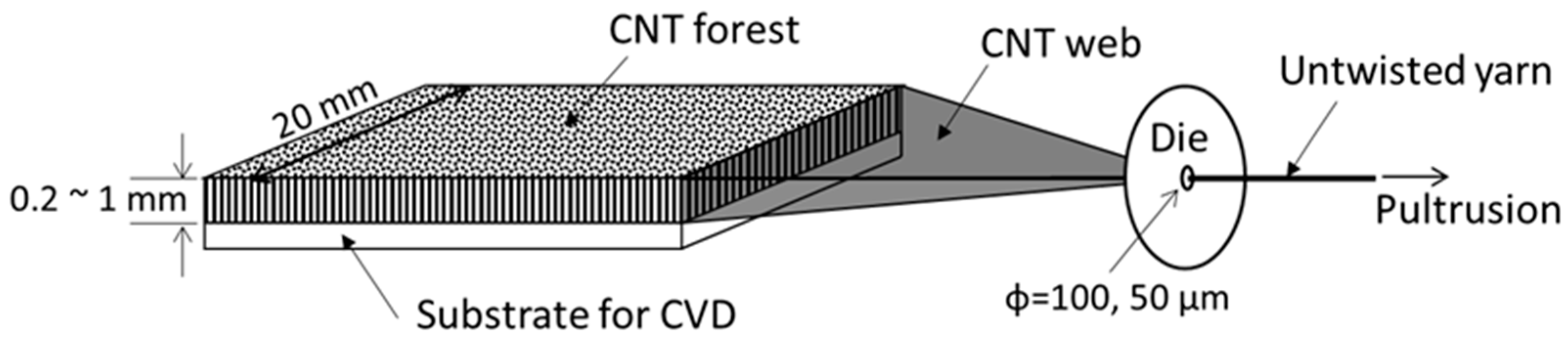
2.3. Fabrication of Carbon Nanotube Untwisted Yarn

Untwisted yarns can be produced by passing a CNT web through a die as shown in Figure 1, where CNTs are almost aligned in the drawn direction [15]. The die diameter was 50 μm for the 10 nm CNT and 100 μm for the 25 nm CNT and 40 nm CNT. The drawing speed was 10 mm/s. The untwisted yarns were then densified by applying ethanol to untwisted yarns and drying [41]. The SEM images of densified untwisted yarns are shown in Figure 2 and the densities are listed in Table 2. In this study, the amount of a CNT web was controlled so that the density of the densified untwisted yarns was around 0.4 g/cm3.

2.4. Annealing

Densified untwisted yarns were stored in a carbon crucible and the crucible was placed in a resistance heating furnace. After evacuation, Ar gas was introduced into the furnace. The temperature in the furnace was increased at the rate of 20 °C/min up to 2800 °C and kept at 2800 °C for 1 h for annealing.

2.5. Measurement of Crystallinity of CNT

The crystallinity of MWNT was characterized by using Raman spectroscopy (XploRA, Horiba Ltd, Kyoto, Japan). The crystallinity was defined as the intensity ration ( I G / I D ) of the G-band (1580 cm−1) and D-band (1350 cm−1) of the Raman spectra, where the G-band arises from the stretching of C-C bonds and the D-band results from disordered structures of graphene. Thus, a higher I G / I D   ratio means better crystallinity. Raman spectra of three points were measured for each condition, and the averaged value was used as the representative I G / I D ratio.

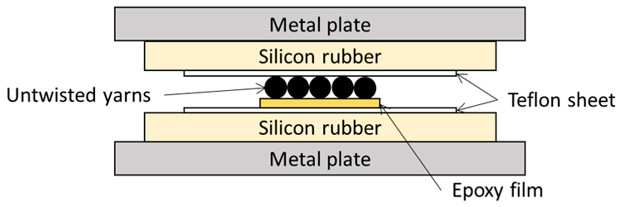
2.6. Fabrication of Unidirectional MWNT Reinforced Epoxy Composite

Unidirectional MWNT reinforced epoxy composites were fabricated as shown in Figure 3. Five untwisted yarns were closely placed on an epoxy adhesive film and hot-pressed.
The volume fraction of CNT was evaluated by using the following equation.
V C N T = w f ρ C N T w f ρ C N T + 1 w f ρ m × 100
where ρ C N T is the density of MWNT (assumed to be 2.1 g/cm3 for 40 nm CNT, 1.9 g/cm3 for 25 nm CNT and 1.6 g/cm3 for 10 nm CNT; see Appendix A for details), ρ m is the density of epoxy (1.16 g/cm3) and w f is the weight fraction of MWNT that was calculated from the weight of the untwisted yarns used and the resulting composite.

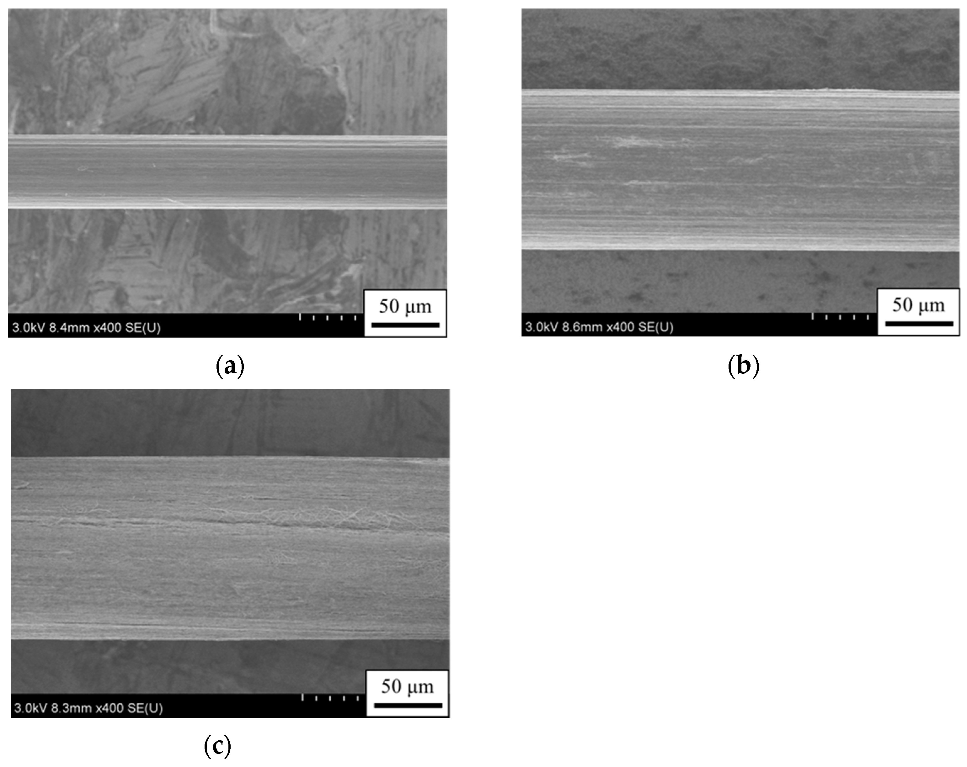
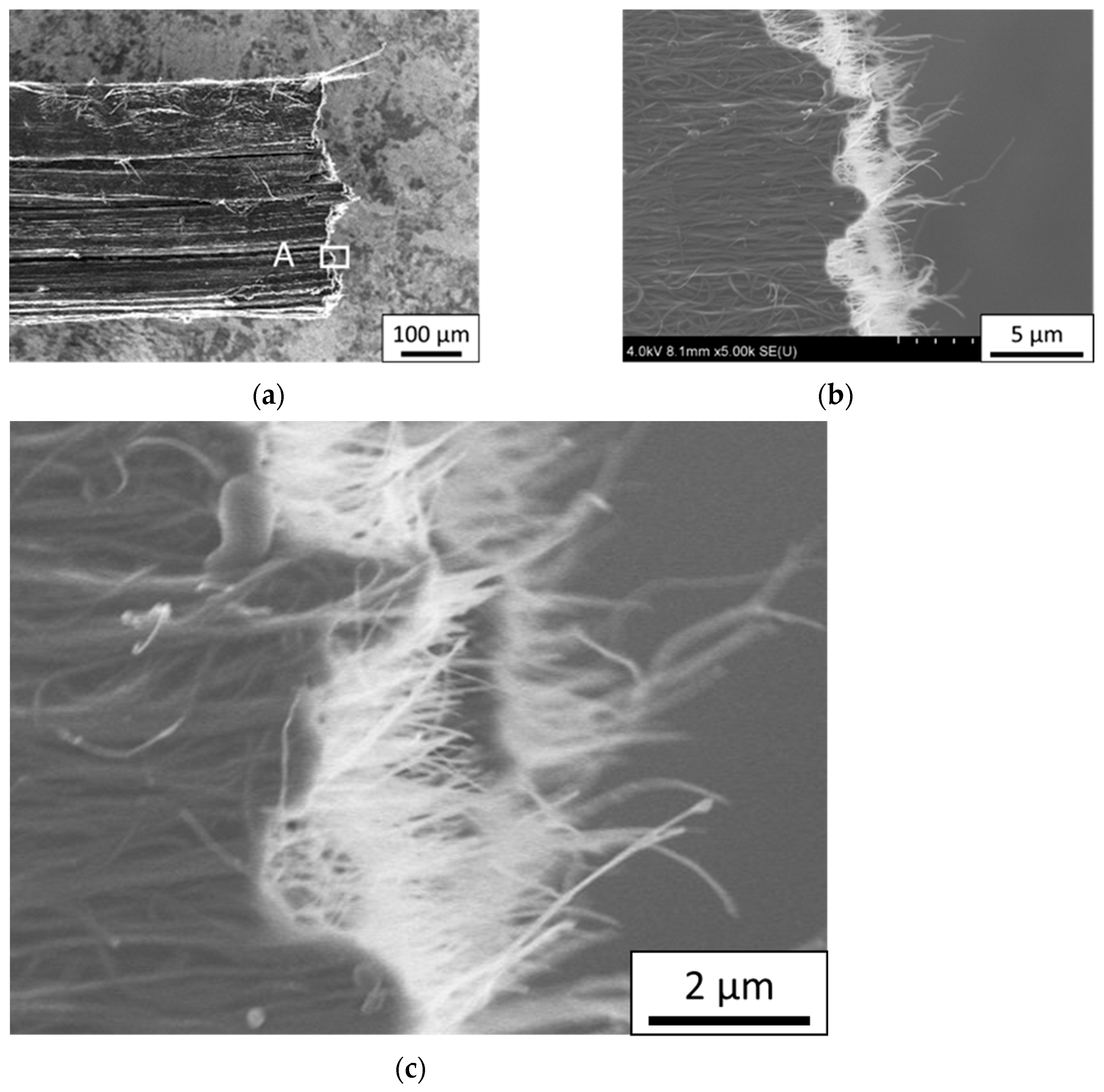
2.7. SEM Observation

A field emission scanning electron microscope (FE-SEM) (SU8030, Hitachi High-Tech Corporation, Tokyo, Japan) was used for observations of untwisted yarns and the fracture surfaces of composite materials. The scanning transmission electron microscopy (STEM) mode of the FE-SEM was used for observations of MWNTs.

2.8. Tensile Test

To evaluate the tensile properties of untwisted yarns and composite specimens, tensile tests were conducted by using the following method, which was similar to the tensile testing method in JIS R7606, “Carbon fibre—determination of the tensile properties of the single filament specimens”. An untwisted MWNT yarn or a composite specimen of 5 cm long was glued at both ends on a U-shaped paper mount with adhesive (cyanoacrylate type), as shown in Figure 4. The gauge length was set to 15 mm. After a specimen adhered to a paper mount was chucked, the paper mount was cut along the dashed line in the center before the tensile test. The tensile tests were conducted at a crosshead speed of 1 mm/min at room temperature in air. A non-contact extensometer was used to measure elongation. The number of tests was 5 or more in each fabrication condition. The cross-sectional area was evaluated from an FE-SEM image of a fracture surface.

3. Results

3.1. Crystallinity of MWNT

The intensity ratios I G / I D are listed in Table 3.
The intensity ratios of as-produced yarns were 1.4–2.9 and those of annealed yarns increased to around 20 for every diameter. The results indicated that the annealing significantly reduced the number of defects in MWNTs.

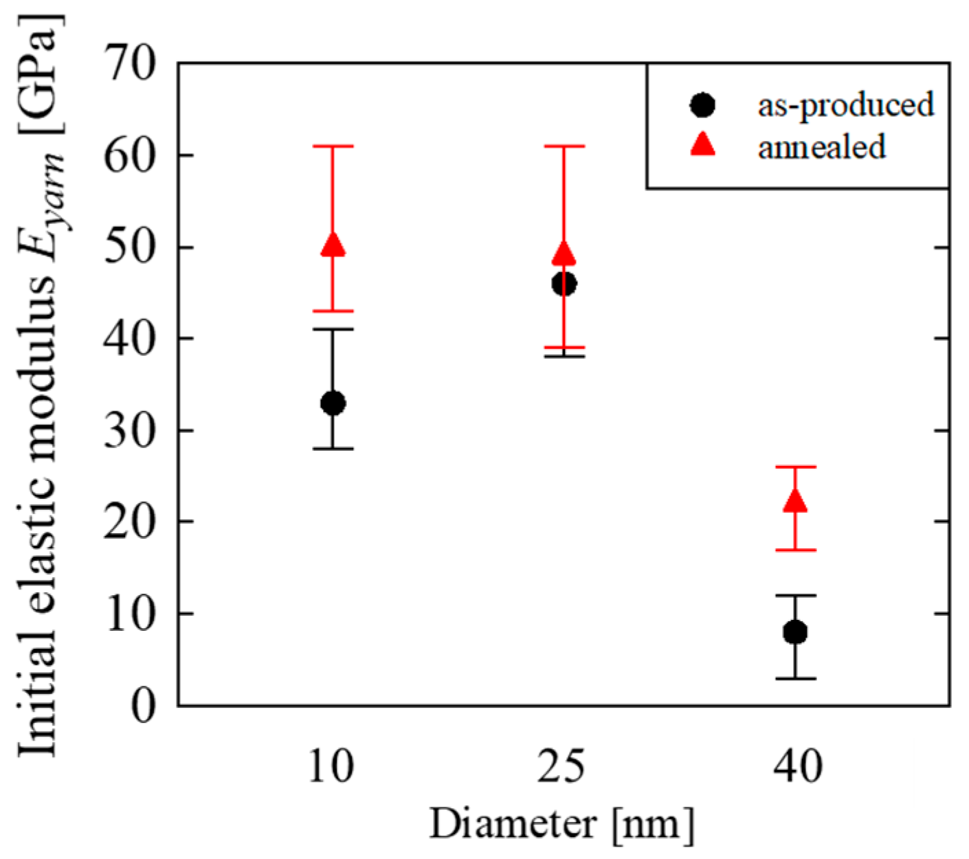
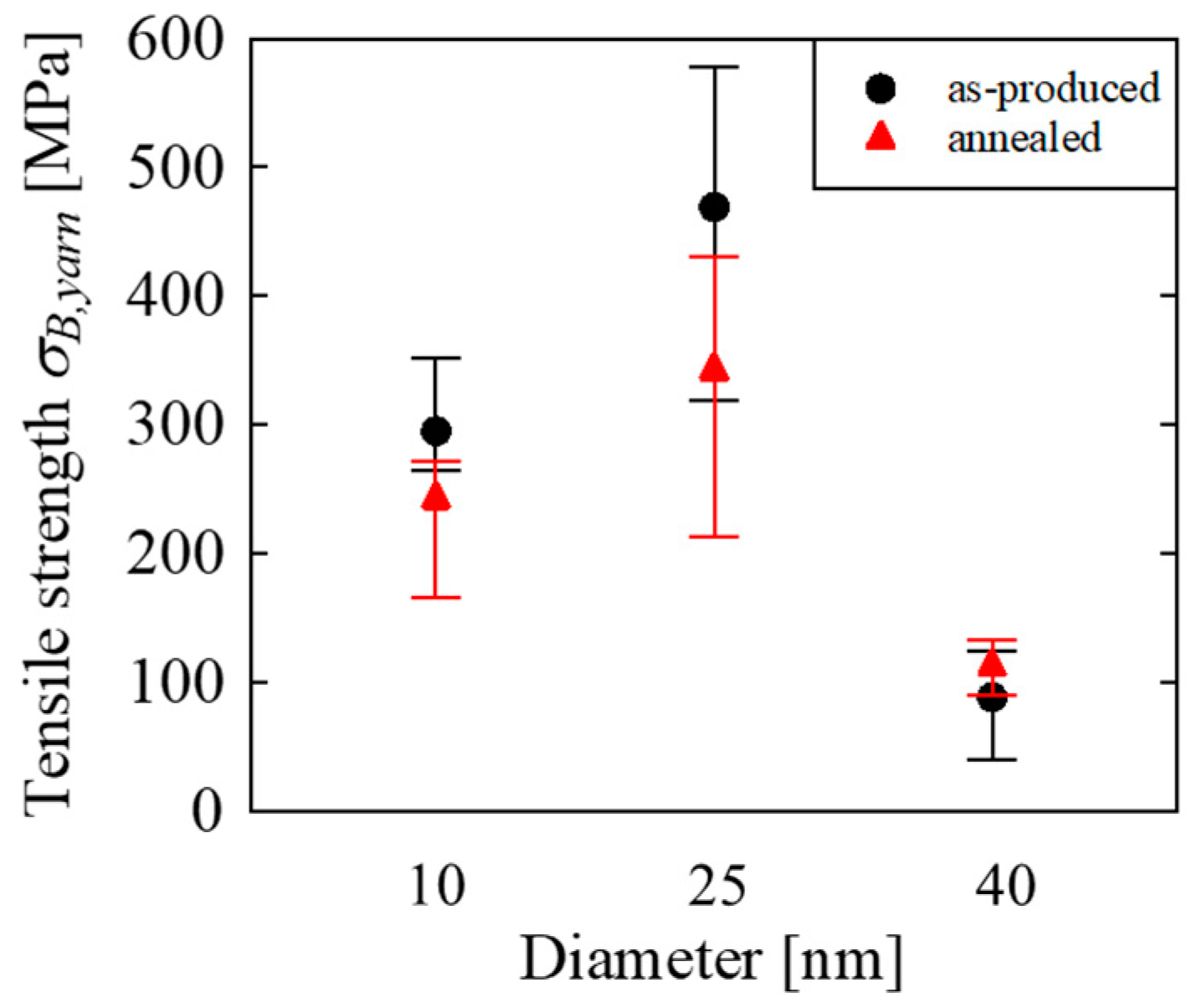
3.2. Tensile Property of Untwisted Yarn

Typical stress–strain curves of untwisted yarns are shown in Figure 5. The initial elastic modulus and tensile strength are plotted in Figure 6 and Figure 7, respectively. The initial elastic moduli were calculated from the slope between ε = 0.05 %     and   0.25 %   . In the figures, the error bars represent the maximum and minimum values. Figure 8, Figure 9 and Figure 10 show side views of typical breaking points of untwisted yarns. As stated previously, the lengths of MWNTs were 200 μm for the 10 nm CNT, 500 μm for the 25 nm CNT and 1000 μm for the 40 nm CNT. Except for the untwisted yarn of the as-produced 10 nm CNT, the length involved in the fracture surface of an untwisted yarn was much shorter than half the CNT length, implying that the tensile strength of untwisted yarns was mainly governed by breakage of MWNTs, not slippage between MWNTs, as discussed later. In contrast, the length involved in the fracture surface of the untwisted yarn of as-produced 10 nm MWNT was about half of the MWNT length (i.e., 100 μm), and thus the final failure of the untwisted yarn would be dominated by slippage between MWNTs.

3.3. Evaluation of Tensile Properties of MWNT

Young’s moduli of MWNTs were roughly estimated by using an analytical method proposed by the authors [41]. In the analysis, an untwisted yarn is modeled as a CNT surrounded by an equivalent homogeneous medium, as shown in Figure 11. The normal stress distribution in the axial direction of the CNT is evaluated by using a shear-lag model, and the secant modulus of the untwisted yarn is obtained as a function of the applied stress to the yarn. According to the analytical method, Young’s modulus of a CNT composed of an untwisted yarn E C N T can be roughly estimated from the initial elastic modulus of the untwisted yarn E y a r n .
E C N T = E y a r n V p f
where V p f is the packing fraction of the CNT in the untwisted yarn. The packing fraction of the CNT of a yarn was calculated as the density of a yarn divided by the density of an MWNT, where the density of a yarn was determined from the linear density of a yarn and the cross-sectional area, and the density of the MWNT was assumed to be 2.0 g/cm3.
In this paper, the cross-sectional area of MWNT A was defined as the area enclosed by the outmost graphene layer, i.e., A = π d 2 / 4 , where d is the diameter of the MWNT.
An untwisted yarn is considered as a unidirectionally aligned bundle of MWNTs, and load transfer between MWNTs occurs due to shear stress acting on MWNT surfaces. Since the aspect ratio of MWNTs is considerably high, an untwisted yarn can be regarded as a unidirectionally aligned bundle of a continuous MWNT from the mechanical point of view. Next is discussed the ultimate strength when tensile loading is applied to an untwisted yarn. The situation is exactly the same as the discussion for the ultimate strength of a unidirectionally reinforced composite material by Curtin [42]. Curtin pointed out that successive fiber fragmentation occurs before final failure if tensile loading is applied to a composite, and the ultimate strength of the composite is governed by the statistical property of the tensile strength of fiber, fiber dimensions and shear stress acting on fiber surfaces. The important point in Curtin’s discussion is that increasing tensile loading causes the accumulation of fiber breakage, and the composite fails when the load-carrying capacity of the composite reaches the maximum value as a result of the accumulation of fiber breakage. That means that the ultimate strength of the composite is mainly governed by fiber breakage, and similarly the tensile strength of an untwisted MWNT yarn is mainly governed by the breakage of the MWNT if continuum mechanics is applicable to an untwisted MWNT yarn. Thus, the average tensile strength of MWNTs composed of an untwisted yarn can be roughly estimated from the tensile strength of the untwisted yarn if the failure mode is supposed to be the breakage of MWNTs.
Let us consider a situation that an untwisted yarn breaks without slipping MWNTs until the final failure. The situation gives the highest tensile strength of an untwisted yarn. In this case, the axial tensile stress of every MWNT is uniform. Thus, the force equilibrium provides the relationship between the tensile strength of the untwisted yarn σ B , y a r n and the tensile strength of the MWNT σ B , C N T .
σ B , y a r n = σ B , C N T V p f
As a second situation, assume that load transfer between MWNTs is performed by slippage between MWNTs. This implies that shear stress acting on the surface of an MWNT due to van der Waals forces from adjacent MWNTs is uniform. If the length of the MWNT is enough long, the untwisted yarn can fail due to breakage of MWNTs. Among such situations, the lowest tensile strength is given when the normal stress in the center only reaches the tensile strength of an MWNT, as shown in Figure 12. In this case, the force equilibrium gives the following equation between the tensile strength of the untwisted yarn and the tensile strength of the MWNT.
σ B , y a r n = σ B , C N T 2 V p f
The above two situations provide a range of an estimate of the tensile strength of an MWNT.
σ B , y a r n V p f σ B , C N T 2   σ B , y a r n V p f

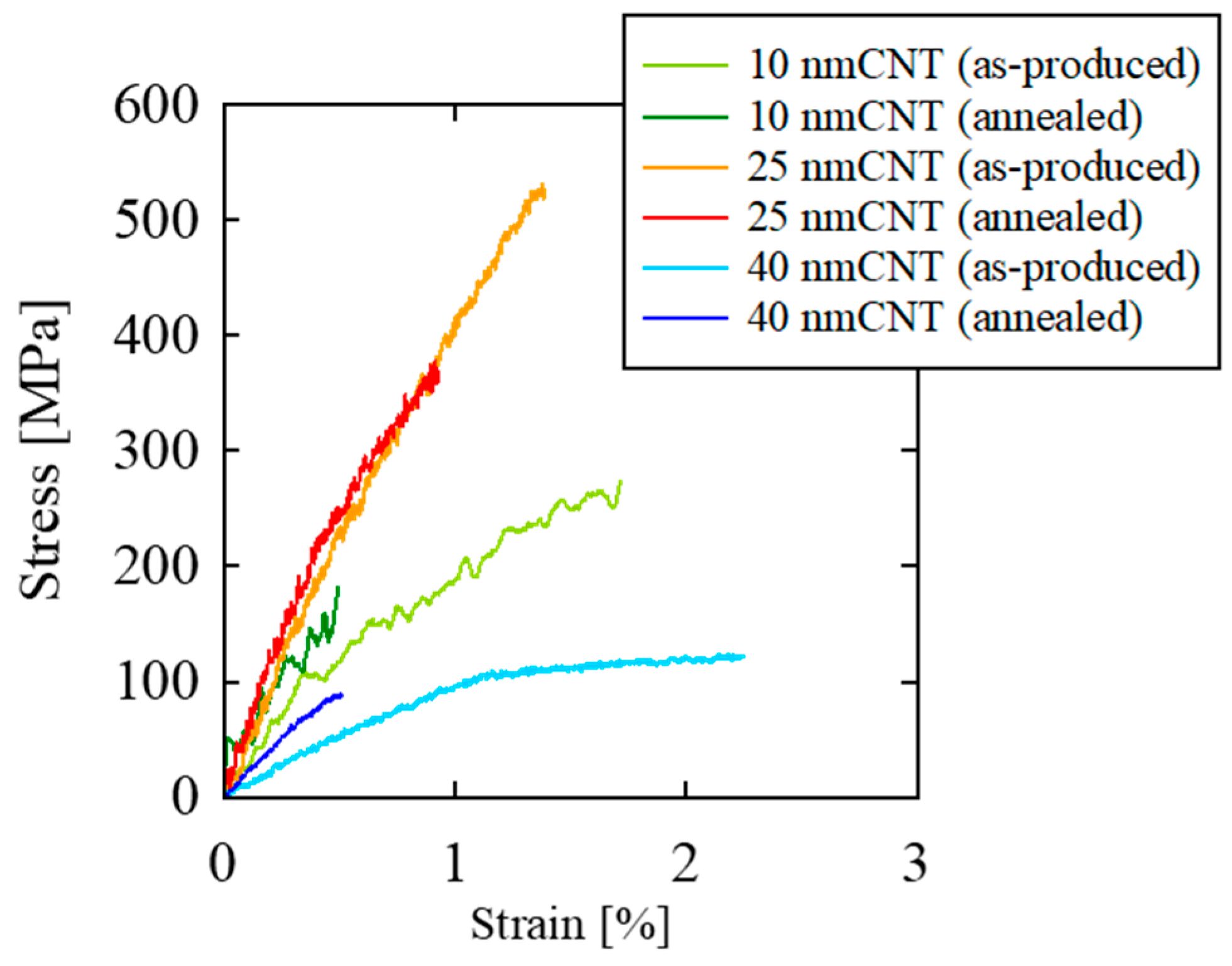
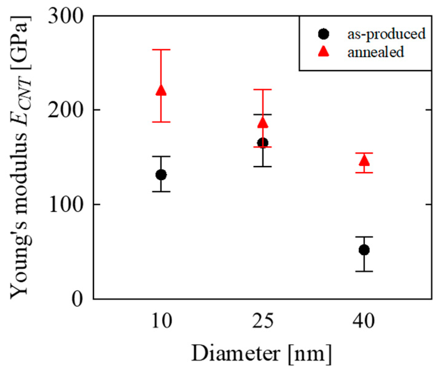
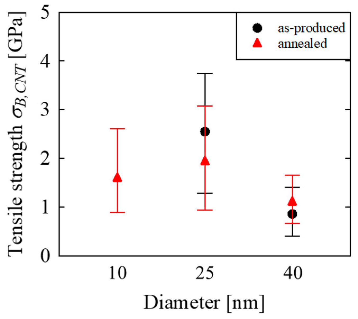
3.4. Tensile Properties of MWNT

Young’s moduli and tensile strengths of MWNTs were estimated by using Equations (2) and (5) from the tensile properties of untwisted yarns. The results are plotted in Figure 13 and Figure 14. In the figures, the error bars represent the maximum and minimum values. Note that estimating the tensile strength of the as-produced 10 nm CNT from Equation (5) is not valid as mentioned, and thus the estimate is not plotted in Figure 14.
The figures show that annealing improved Young’s modulus, especially of the 10 nm CNT and 40 nm CNT. Yamamoto et al. [37] suggested that annealing at an elevated temperature reduces the defects in MWNTs and improves Young’s modulus. In contrast, annealing did not improve the tensile strengths in our case. The reason will be discussed later.
Concerning the diameter, 25 nm CNT and 10 nm CNT showed higher Young’s modulus and tensile strength than 40 nm CNT for as-produced and annealed CNTs as expected. Young’s modulus of annealed 10 nm CNT was higher that of annealed 25 nm CNT, but Young’s modulus of as-produced 10 nm CNT was almost equal to that of as-produced 25 nm CNT. The tensile strength of the annealed 10 nm CNT was not higher than but almost equal to that of the annealed 25 nm CNT. One possible reason for the trend on Young’s modulus is that the crystallinity of the as-produced 10 nm CNT was lower than the as-produced 25 nm CNT. The reason behind the trend of tensile strength is discussed later in the paper.

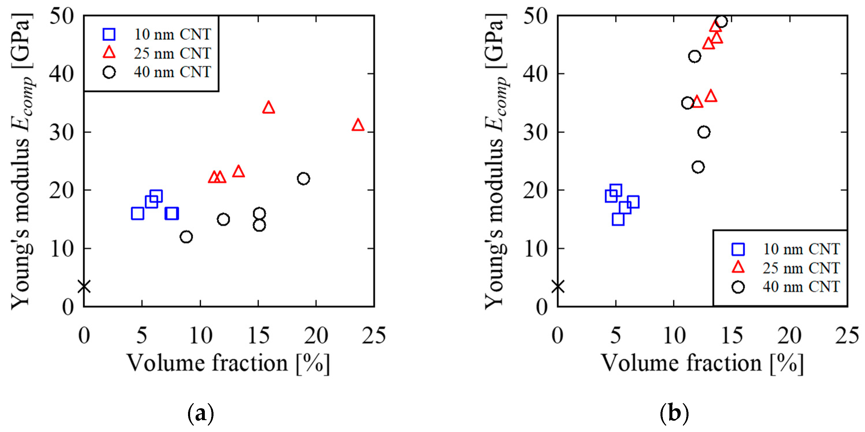
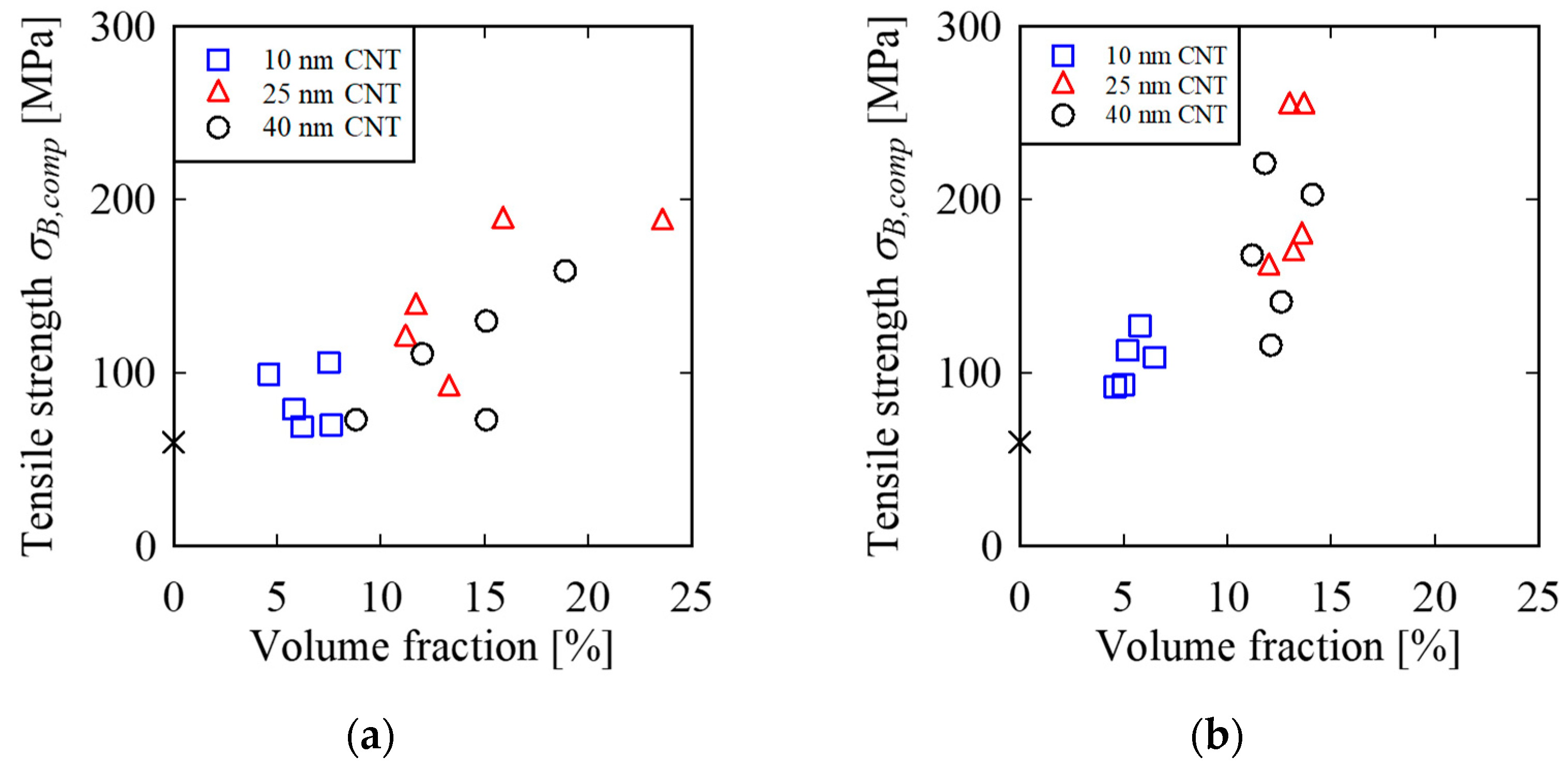
3.5. Tensile Properties of Unidirectional MWNT Reinforced Epoxy Composite

Young’s moduli and tensile strengths of composite specimens are shown in Figure 15 and Figure 16. Young’s moduli were calculated from the slope between ε = 0.05 %   and   0.25 %   . Since the volume fractions of the CNT had large scatter, the results are plotted as a function of the volume fraction of the CNT. Young’s modulus and the tensile strength of epoxy, E = 3.5 GPa and σ B = 60 MPa, where both are typical values of general-purpose epoxy, are plotted because the tensile tests of epoxy adhesive film were not feasible.
Side views and front views of a typical fracture surface are shown in Figure 17 and Figure 18. The specimen was produced by using untwisted yarns of as-produced 40 nm CNT. The fracture surface was perpendicular to the loading direction, and the pull-out length of the MWNT was about 5 μm or less, which was much smaller than the length of the MWNT, i.e., 1000 μm. Figure 18c also shows that the epoxy resin was well impregnated into MWNT yarns. The fracture surface and the state of resin impregnation into yarns were similar to the other composite specimens. It is noteworthy that the morphology of the fracture surface was quite similar to conventional unidirectional continuous fiber reinforced composites. The observation suggested that the fracture mode of the unidirectional MWNT reinforced epoxy composites was fiber breakage.

4. Discussion

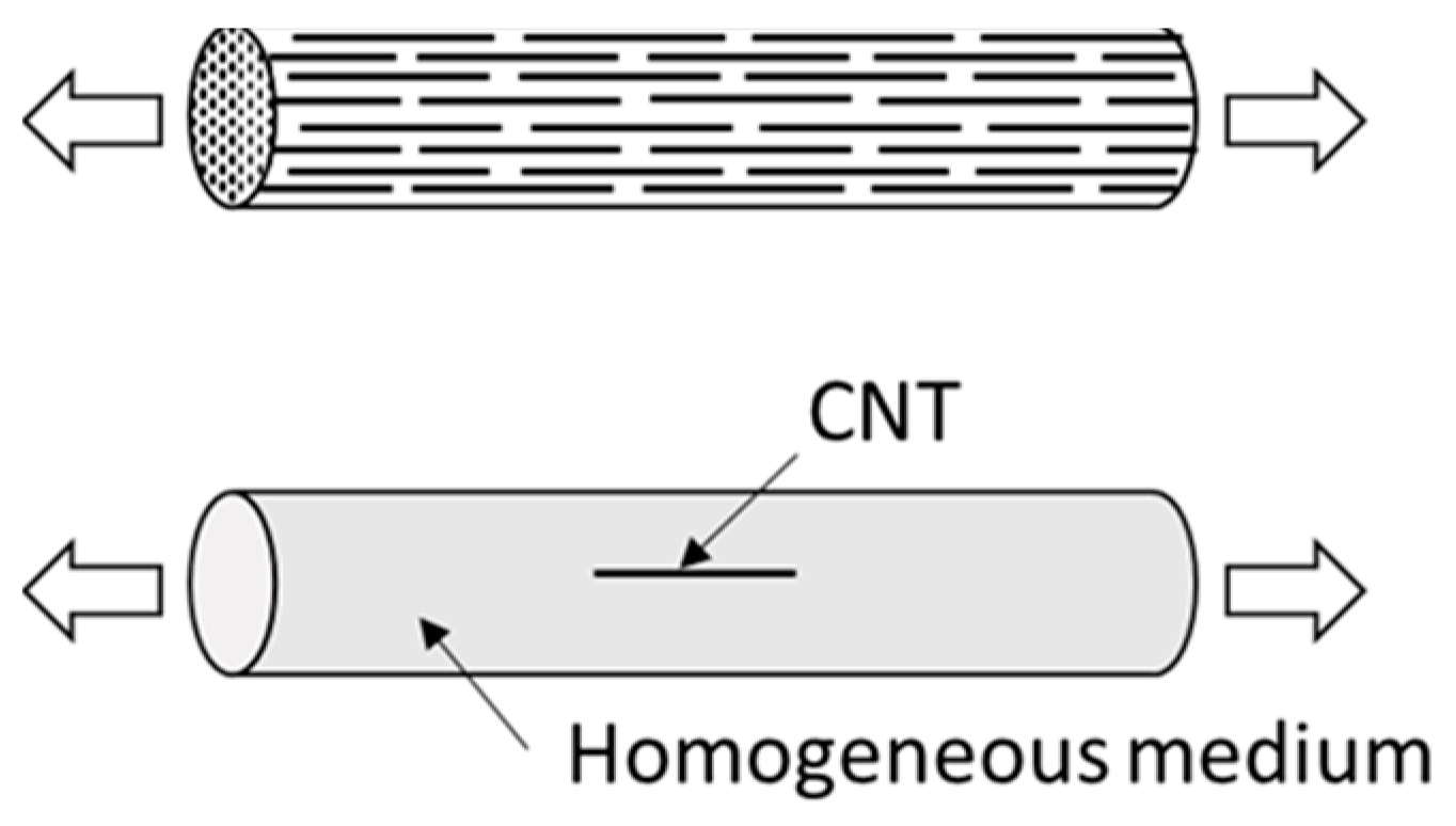
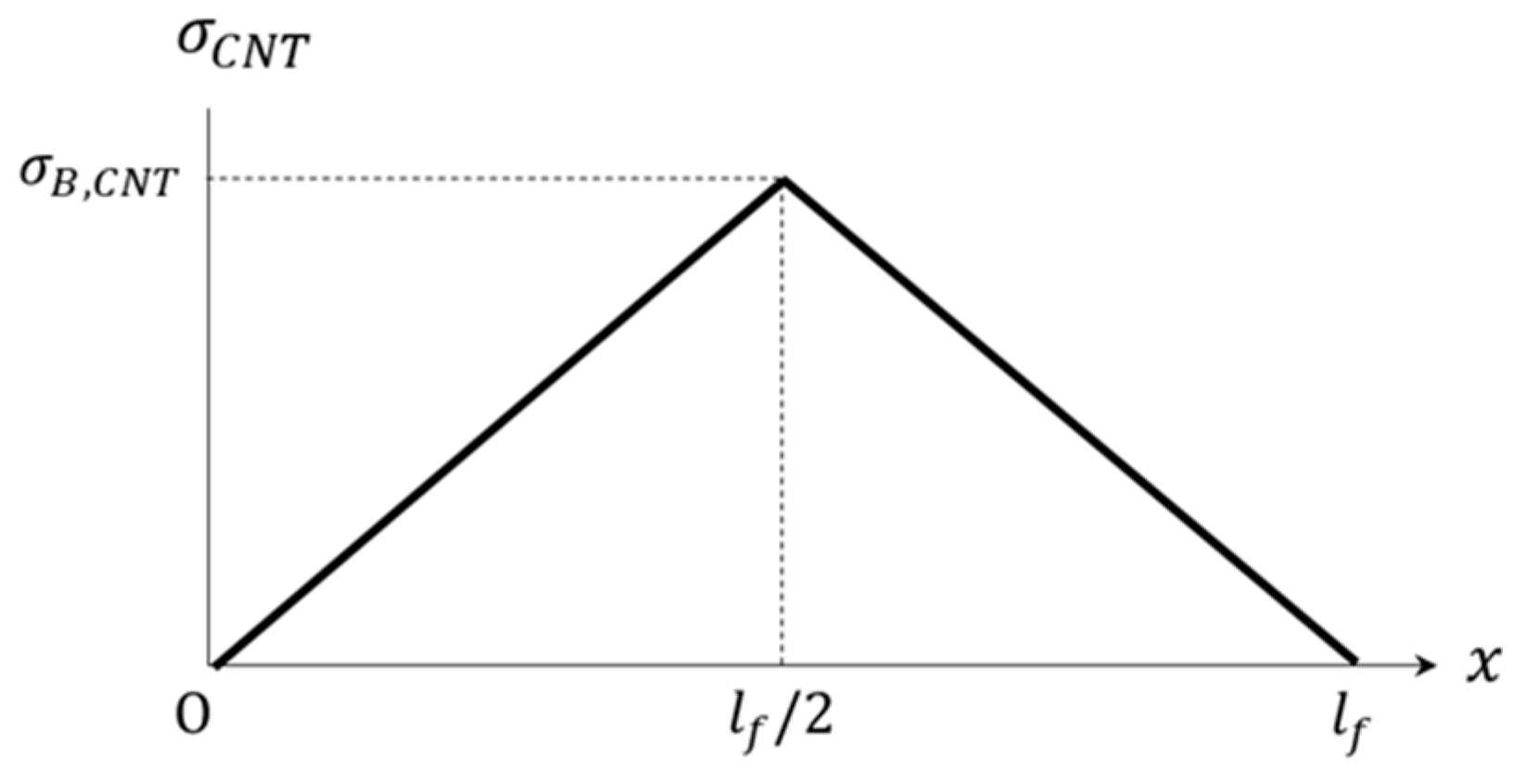
4.1. Effect of Evaluation Method of Tensile Property of MWNT

The authors of this paper conducted tensile tests in n of three MWNTs with about 30 nm diameters [40], which were produced by the same method for producing a 25 nm CNT and whose crystallinity was almost the same as that of the as-produced 25 nm CNT. The average Young’s modulus and tensile strength obtained by the tensile tests in an SEM were 197 GPa and 8.4 GPa, respectively. Young’s modulus and tensile strength of the as-produced 25 nm CNT estimated from the tensile properties of untwisted yarns in this study were 165 GPa and 2.6 GPa, respectively.
With regard to Young’s modulus, the value obtained by tensile tests in an SEM was similar to the value estimated from the tensile properties of untwisted yarns. The result means that the estimating method described in Section 3.3 can provide a reasonable estimate of Young’s modulus of spinnable MWNTs.
On the other hand, the tensile strength obtained by tensile tests in an SEM was about three times higher than the estimate from tensile properties of untwisted yarns. It is well known that tensile strength may be affected by the risk volume, especially if the specimen fails in a brittle manner. Assuming that the two-parameter Weibull distribution model is applicable to the tensile strength of an MWNT, the effect of the risk volume on tensile strength can be predicted [43] by
σ V 1 σ V 2 = ( V e 2 V e 1 ) 1 m
where σ V is the tensile strength of a specimen, V e is the effective volume of a specimen and m is the shape parameter. The effective volume is calculated from
V e = V ( σ σ 0 ) m d V
where σ 0 is the maximum tensile stress that arose in a specimen. For simplicity, let us assume that tensile stress in a CNT is uniform. Substituting l 1   = 10 μm and d 1   = 32 nm for a tensile test of a CNT in an SEM [40], l 2   = 500 μm and d 2   = 25 nm for a tensile test of an untwisted yarn, and m   = 2.7 [38] into Equation (6) yields
σ V 1 σ V 2 =   ( l 2 d 2 2 l 1 d 1 2 ) 1 m 3.5
Note that Equation (8) gives the upper limit, because the tensile stress acting on a CNT in an untwisted yarn may not be uniform as a result of slippage between CNTs. Equation (8) is a rough evaluation, yet provides a reasonable estimate of the ratio of tensile strengths in our experiments. This implies that the difference between the tensile strength obtained by a tensile test of a CNT in an SEM and an estimate from the tensile strength of an untwisted yarn was primarily caused by the difference in the risk volumes.

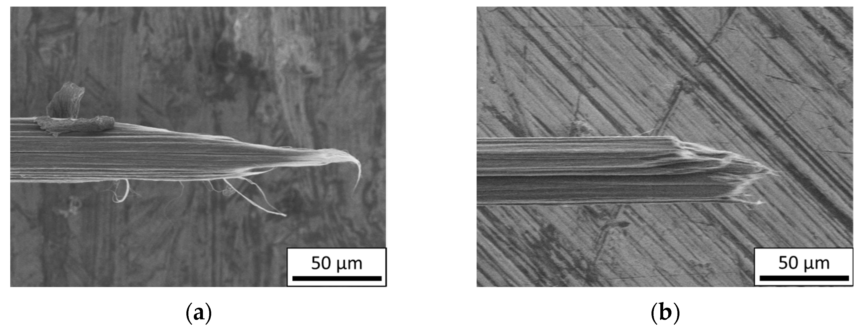
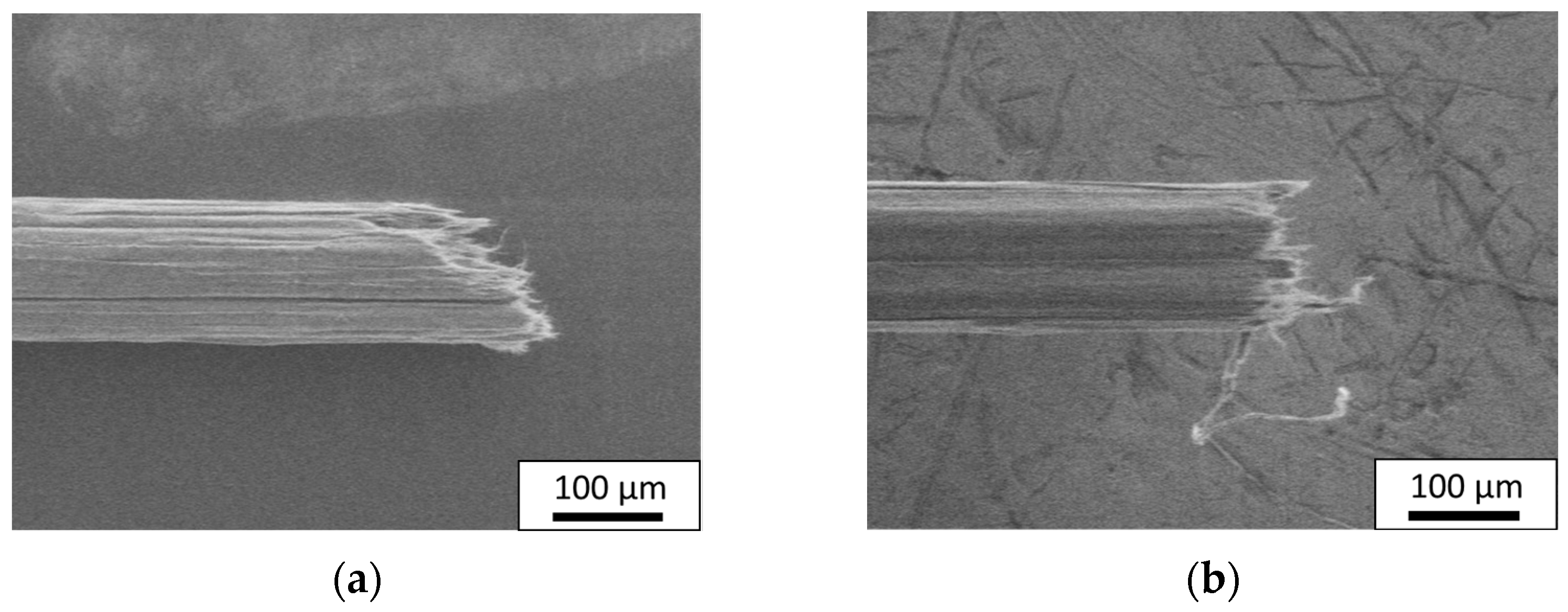
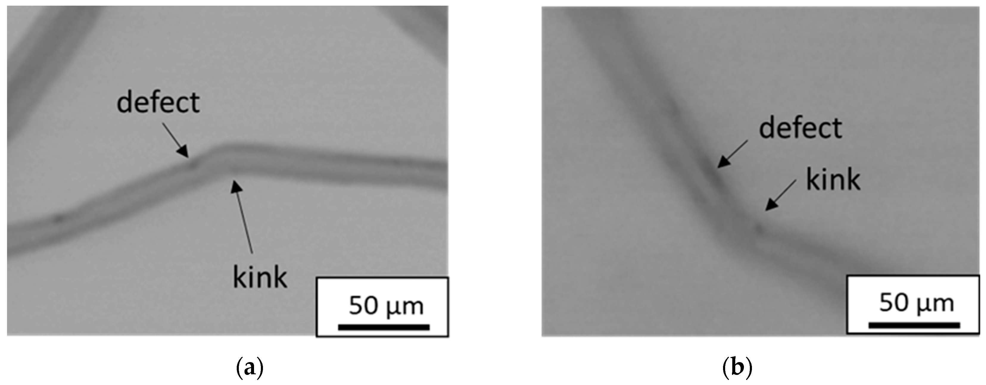
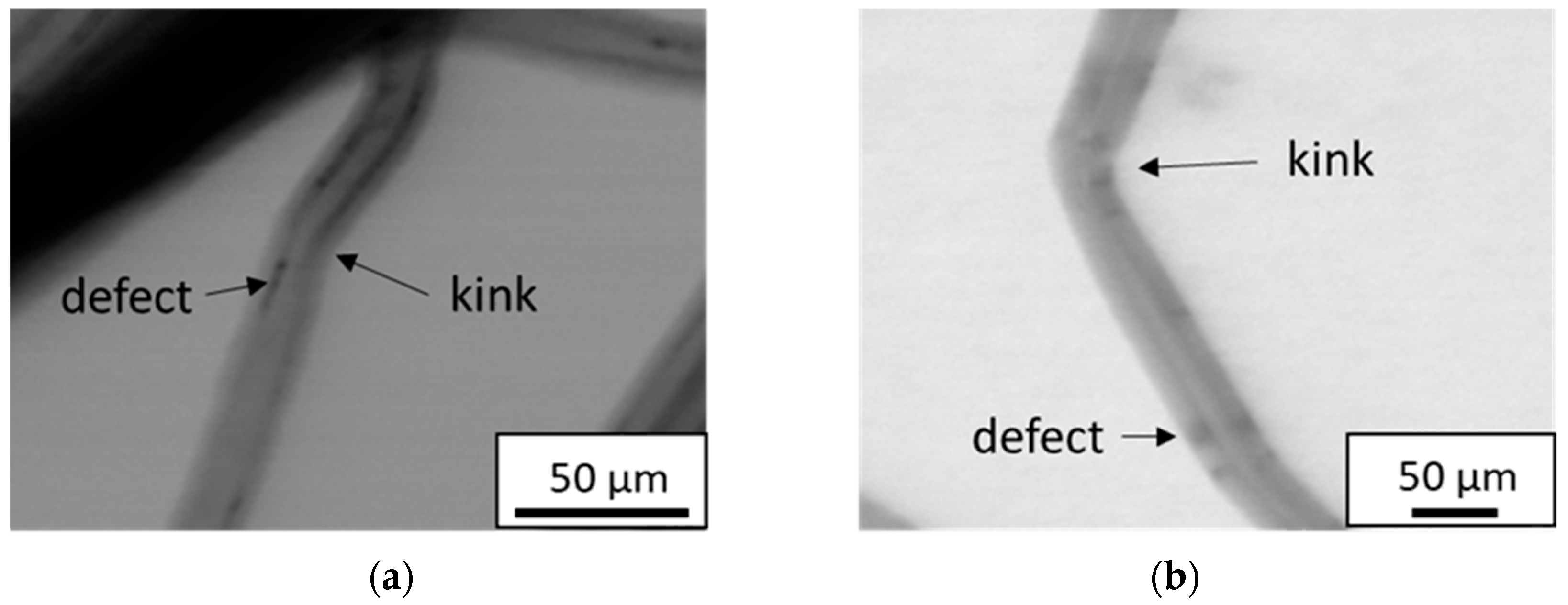
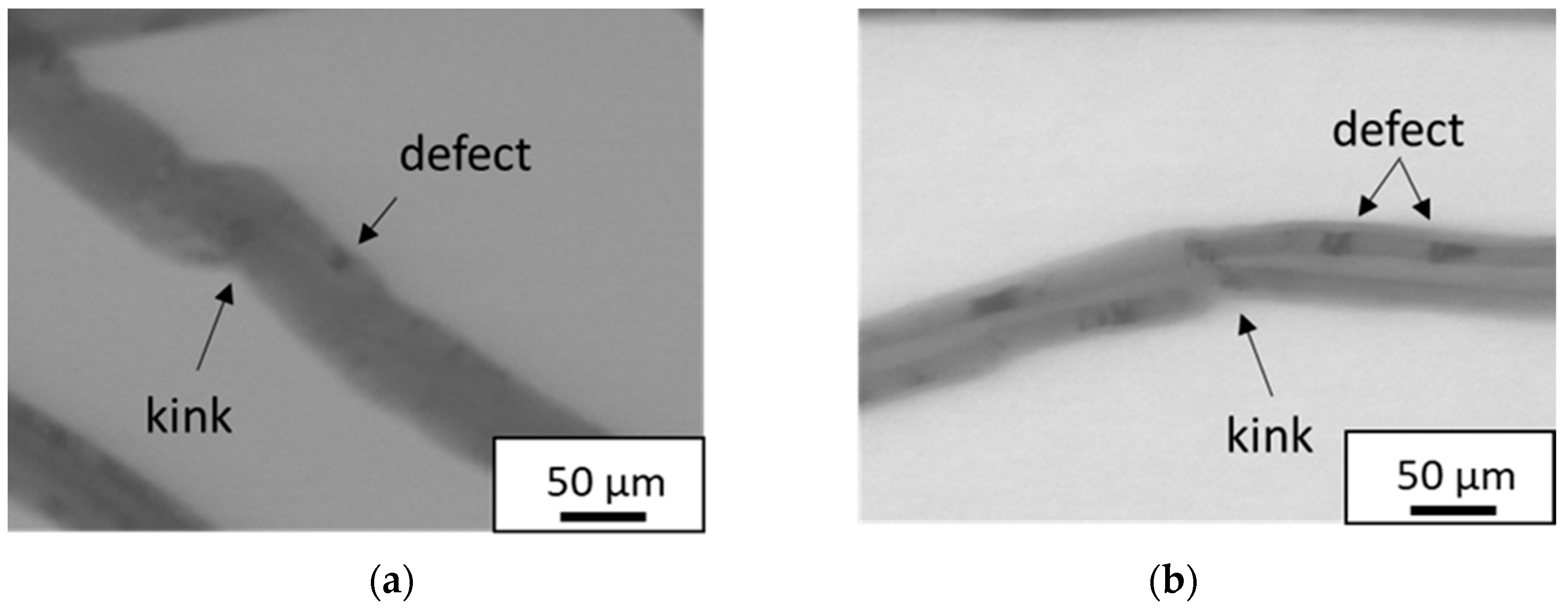
4.2. Kink and Disordered Structure of Fracture of CNT

Shirasu et al. [38] pointed out that a discontinuity of graphene layers such as a kink and a disordered structure would be the fracture origin of a MWNT. Thus, STEM observations of MWNTs before and after annealing were conducted, and the STEM images are shown in Figure 19, Figure 20 and Figure 21. In the figures, kinks exist in graphene layers where MWNTs bend sharply, and defects exist in graphene layers where the color is darker. Figures showed that kinks and disordered structures existed in as-produced CNTs and did not disappear by annealing at 2800 °C for 1 h even though the crystallinities of annealed CNTs were significantly improved, implying that the remaining kinks and disordered structures in annealed CNTs are the reasons why the tensile strengths were not improved by annealing.
The tensile strength of the annealed 10 nm CNT was not higher than but similar to that of the annealed 25 nm CNT, contrary to our expectation. This was also probably because of the remaining kinks and disordered structures, and the tensile strength of MWNTs might be very sensitive to kinks and disordered structures when the diameter of MWNTs is thin.

4.3. Tensile Property of Unidirectional MWNT Reinforced Epoxy Composite

The composite materials produced in this study were reinforced by discontinuous nanotubes but were regarded as continuous reinforcement because the aspect ratios of MWNTs used were extremely high, i.e., 20,000 or more. To discuss the contribution of the tensile property of MWNTs to the bulk tensile property of composite materials, Young’s moduli and tensile strengths of MWNTs were estimated backward by using the rule of mixtures and the Young’s moduli E c o m p and tensile strengths σ B , c o m p of unidirectional MWNT reinforced epoxy composites.
E c o m p = E C N T V C N T + E e p o x y ( 1 V C N T )
σ B , c o m p = σ B , C N T V C N T + E e p o x y ε f , c o m p ( 1 V C N T )
where E e p o x y is Young’s modulus of epoxy, V C N T is the volume fraction of CNT and ε f , c o m p is the failure strain of a composite material. Note that the accuracy of the above backward estimation is not high because of the considerable simplifications of modeling and uncertainties of the volume fractions of CNT, but the estimates will provide useful information if compared with the rough estimates in Section 3.4.
Figure 22 and Figure 23 show the estimates. The error bars in the figures represent the maximum and minimum values. The backward estimates of Young’s moduli and tensile strengths ranged from 96–298 GPa and 0.8–1.9 GPa, respectively. Nam et al. investigated the effect of diameter [29] and annealing [32] on the tensile property of unidirectional MWNT reinforced epoxy composites produced by using MWNT sheets as the preform. Young’s moduli of MWNTs were estimated by using the rule of mixtures, as in this study, and they found that annealing and decreasing the diameter of MWNTs were effective to increase Young’s modulus. The trend was similar to that shown in Figure 22.
In addition, the estimates from the tensile properties of untwisted yarns shown in Figure 13 and Figure 14 ranged from 52–220 GPa and 0.9–2.6 GPa, respectively. The estimates from untwisted yarns provided similar values obtained by the backward estimates. The results mean that the bulk tensile property of composite materials was primarily determined by the tensile property of MWNTs.
Curtin [42] proposed a model predicting the ultimate tensile strength σ u of unidirectional fiber reinforced composite materials provided that the reinforcing fiber is brittle, the tensile strength of the reinforcing fiber obeys the two-parameter Weibull distribution and Young’s modulus of the matrix is much lower than that of the reinforcing fiber.
σ u = V f σ c ( 2 m + 2 ) 1 m + 1 ( m + 1 m + 2 )
where σ c is
σ c = ( σ 0 m τ L 0 r ) 1 m + 1
where τ is the shear stress acting on fiber surfaces near both ends of broken fibers in the matrix, r is the diameter of the fiber and L 0 is the fiber length when the tensile strength distribution was measured. The shear stress acting on fiber surfaces τ can be estimated from the pull-out length appearing in a fracture surface of an untwisted yarn, according to Ref. [42], and the estimate was 0.6 MPa in our case [41].
For example, let us assume that the shape parameter m is improved from 2.7 to 10 and substitute L 0   = 10 μm,   r   = 16 nm, σ 0   = 8.4 GPa [40] and τ   = 0.6 MPa [41] into Equation (11). The trial calculation gives the result that the tensile strength of the composite material will be improved as much as about two times. Since the scatter of the tensile strength of MWNTs is too large, decreasing the scatter will fairly improve the tensile strength of composite materials as well as increase the tensile strength of MWNTs.

5. Conclusions

In this study, as-produced and annealed untwisted yarns using spinnable MWNTs with three different diameters were prepared, and the tensile properties of spinnable MWNTs were estimated from the tensile properties of the untwisted yarns to investigate the effect of annealing and diameter on the overall tensile property of spinnable MWNTs. Furthermore, tensile tests of unidirectional MWNT reinforced epoxy composites were conducted, and the contribution of the tensile property of MWNT to that of the composite was also discussed. The following conclusions were obtained:
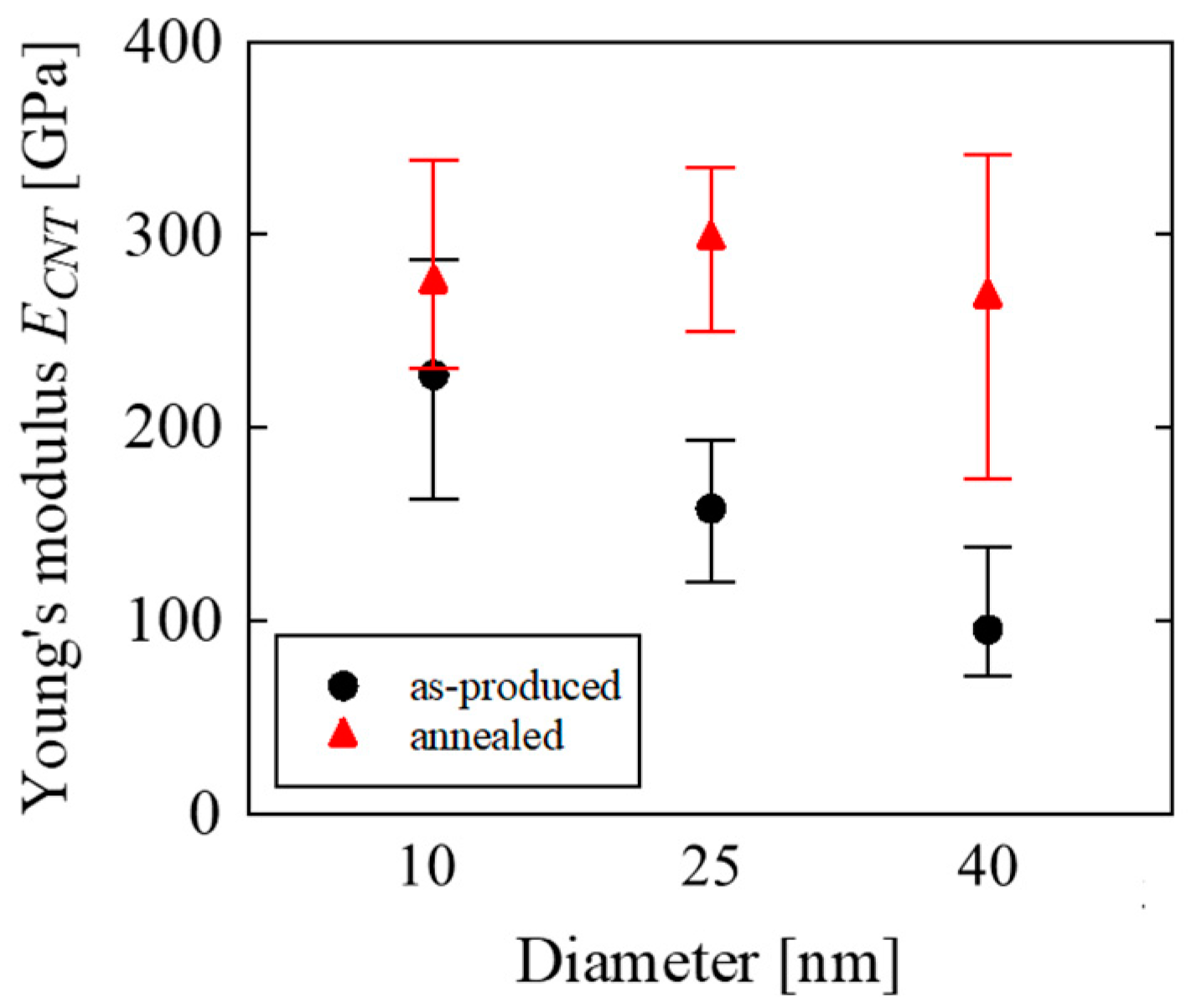
  • Annealing at 2800 °C for 1 h and decreasing the diameter from 40 nm to 25 or 10 nm was effective to improve Young’s modulus of MWNTs.
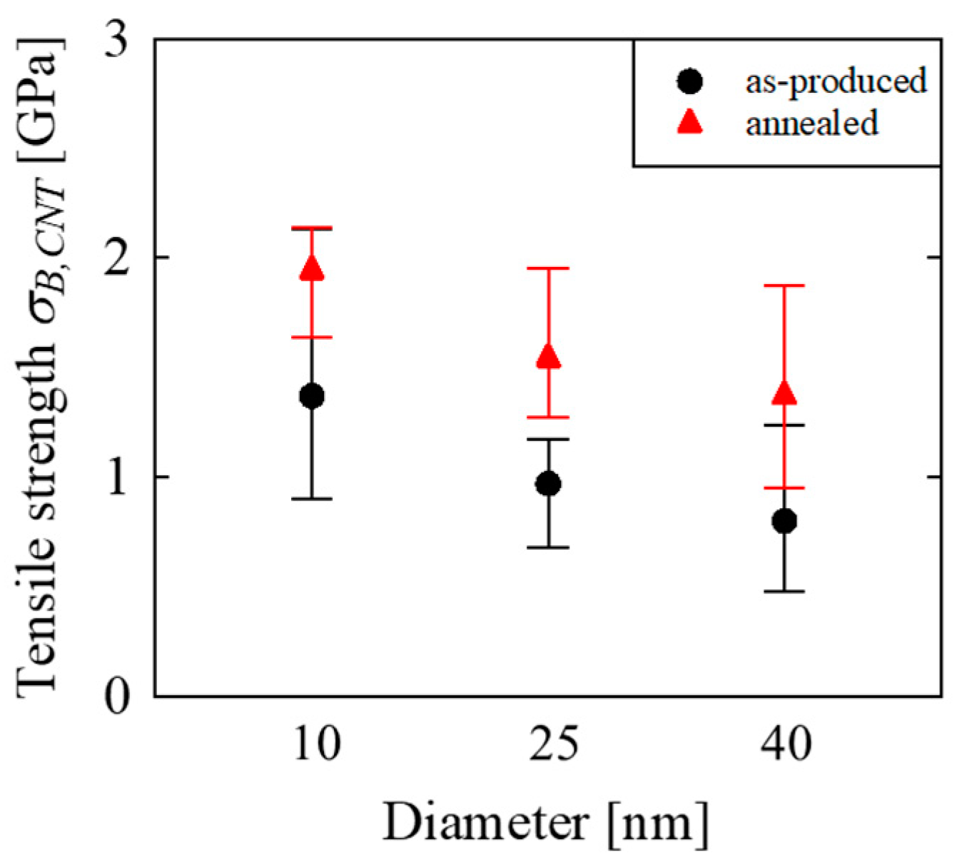
  • Decreasing the diameter of MWNTs from 40 nm to 25 or 10 nm was effective in improving the tensile strength but annealing at 2800 °C for 1 h was not effective in improving the tensile strength. STEM observations suggested that this was probably because the annealing did not result in the significant decrease in kinks or disordered structures such as discontinuity of graphene layers.
  • For the as-produced 25 nm CNT, the estimate of Young’s modulus from the tensile properties of untwisted yarns was close to the experimental result of tensile tests of the as-produced 30 nm CNT in an SEM, but the estimate of the tensile strength was about one third of the experimental tensile strength in an SEM. The difference in the risk volumes is the reason for the discrepancy in the tensile strengths.
  • The bulk tensile property of unidirectional MWNT reinforced epoxy composites was primarily determined by the tensile property of MWNTs.
These results support previous findings from a limited number of tensile tests in an SEM/TEM, and also reveal the validity of estimating the tensile properties of individual CNTs using simple tensile tests of untwisted yarns. In addition, the discussion on composite materials suggests that the tensile property of composite materials can be enhanced by improving the tensile property of MWNTs.

Author Contributions

Conceptualization, Y.S. and T.F.; methodology, Y.S and Y.I.; investigation, N.T.; writing—original draft preparation, N.T.; writing—review and editing, Y.S., T.F. and Y.I.; visualization. N.T. and Y.S.; project administration, Y.S. All authors have read and agreed to the published version of the manuscript.

Funding

This research received no external funding.

Institutional Review Board Statement

Not applicable.

Informed Consent Statement

Not applicable.

Data Availability Statement

The data presented in this study are available on request from the corresponding author.

Conflicts of Interest

The authors declare no conflict of interest.

Appendix A

The density of MWNT can be evaluated by the outer and inner diameters (or the outer diameter and the number of layers) based on the specific surface of graphene and the distance between layers assuming that a multi-walled carbon nanotube is composed of concentric shells [44]. By using the values in Table 1, we can evaluate the density of MWNTs used in our study according to Ref. [44]. The evaluated densities were 2.06–2.19 g/cm3 for a 40 nm CNT, 1.75–2.09 g/cm3 for a 25 nm CNT and 1.51–1.69 g/cm3 for a 10 nm CNT.

References

  1. Belytschko, T.; Xiao, S.P.; Schatz, G.C.; Ruoff, R.S. Atomistic Simulations of Nanotube Fracture. Phys. Rev. B 2002, 65, 235430. [Google Scholar] [CrossRef] [Green Version]
  2. Lee, C.; Wei, X.; Kysar, J.W.; Hone, J. Measurement of the Elastic Properties and Intrinsic Strength of Monolayer Graphene. Science 2008, 321, 385–388. [Google Scholar] [CrossRef] [PubMed]
  3. Bai, Y.; Zhang, R.; Ye, X.; Zhu, Z.; Xie, H.; Shen, B.; Cai, D.; Liu, B.; Zhang, C.; Jia, Z.; et al. Carbon Nanotube Bundles with Tensile Strength over 80 GPa. Nat. Nanotechnol. 2018, 13, 589–595. [Google Scholar] [CrossRef] [PubMed]
  4. Jiang, K.; Li, Q.; Fan, S. Spinning Continuous Carbon Nanotube Yarns. Nature 2002, 419, 801. [Google Scholar] [CrossRef] [PubMed]
  5. Zhang, M.; Atkinson, K.R.; Baughman, R.H. Multifunctional Carbon Nanotube Yarns by Downsizing an Ancient Technology. Science 2004, 306, 1358–1361. [Google Scholar] [CrossRef]
  6. Li, Y.L.; Kinloch, I.A.; Windle, A.H. Direct Spinning of Carbon Nanotube Fibers from Chemical Vapor Deposition Synthesis. Science 2004, 304, 276–278. [Google Scholar] [CrossRef]
  7. Zhang, M.; Fang, S.; Zakhidov, A.A.; Lee, S.B.; Aliev, A.E.; Williams, C.D.; Atkinson, K.R.; Baughman, R.H. Strong, Transparent, Multifunctional, Carbon Nanotube Sheets. Science 2005, 309, 1215–1219. [Google Scholar] [CrossRef] [Green Version]
  8. Zhang, X.; Li, Q.; Tu, Y.; Li, Y.; Coulter, J.Y.; Zheng, L.; Zhao, Y.; Jia, Q.; Peterson, D.E.; Zhu, Y. Strong Carbon-Nanotube Fibers Spun from Long Carbon-Nanotube Arrays. Small 2007, 3, 244–248. [Google Scholar] [CrossRef]
  9. Nakayama, Y. Synthesis, Nanoprocessing, and Yarn Application of Carbon Nanotubes. Jpn. J. Appl. Phys. 2008, 47, 8149–8156. [Google Scholar] [CrossRef]
  10. Inoue, Y.; Kakihata, K.; Hirono, Y.; Horie, T.; Ishida, A.; Mimura, H. One-Step Grown Aligned Bulk Carbon Nanotubes by Chloride Mediated Chemical Vapor Deposition. Appl. Phys. Lett. 2008, 92, 213113. [Google Scholar] [CrossRef]
  11. Tran, C.D.; Humphries, W.; Smith, S.M.; Huynh, C.; Lucas, S. Improving the Tensile Strength of Carbon Nanotube Spun Yarns Using a Modified Spinning Process. Carbon 2009, 47, 2662–2670. [Google Scholar] [CrossRef] [Green Version]
  12. Kinoshita, T.; Karita, M.; Nakano, T.; Inoue, Y. Two Step Floating Catalyst Chemical Vapor Deposition Including in Situ Fabrication of Catalyst Nanoparticles and Carbon Nanotube Forest Growth with Low Impurity Level. Carbon 2019, 144, 152–160. [Google Scholar] [CrossRef]
  13. Inoue, H.; Hada, M.; Nakagawa, T.; Marui, T.; Nishikawa, T.; Yamashita, Y.; Inoue, Y.; Takahashi, K.; Hayashi, Y. The Critical Role of the Forest Morphology for Dry Drawability of Few-Walled Carbon Nanotubes. Carbon 2020, 158, 662–671. [Google Scholar] [CrossRef]
  14. Kinoshita, T.; Karita, M.; Chikyu, N.; Nakano, T.; Inoue, Y. Enhancement of Catalytic Activity by Addition of Chlorine in Chemical Vapor Deposition Growth of Carbon Nanotube Forests. Carbon 2022, 196, 391–400. [Google Scholar] [CrossRef]
  15. Sugano, K.; Kurata, M.; Kawada, H. Evaluation of Mechanical Properties of Untwisted Carbon Nanotube Yarn for Application to Composite Materials. Carbon 2014, 78, 356–365. [Google Scholar] [CrossRef]
  16. Cheng, Q.; Wang, J.; Jiang, K.; Li, Q.; Fan, S. Fabrication and Properties of Aligned Multiwalled Carbon Nanotube-Reinforced Epoxy Composites. J. Mater. Res. 2008, 23, 2975–2983. [Google Scholar] [CrossRef] [Green Version]
  17. Mora, R.J.; Vilatela, J.J.; Windle, A.H. Properties of Composites of Carbon Nanotube Fibres. Compos. Sci. Technol. 2009, 69, 1558–1563. [Google Scholar] [CrossRef]
  18. Bogdanovich, A.E.; Bradford, P.D. Carbon Nanotube Yarn and 3-D Braid Composites. Part I: Tensile Testing and Mechanical Properties Analysis. Compos. Part A Appl. Sci. Manuf. 2010, 41, 230–237. [Google Scholar] [CrossRef]
  19. Cheng, Q.F.; Wang, J.P.; Wen, J.J.; Liu, C.H.; Jiang, K.L.; Li, Q.Q.; Fan, S.S. Carbon Nanotube/Epoxy Composites Fabricated by Resin Transfer Molding. Carbon 2010, 48, 260–266. [Google Scholar] [CrossRef]
  20. Cheng, Q.; Wang, B.; Zhang, C.; Liang, Z. Functionalized Carbon-Nanotube Sheet/Bismaleimide Nanocomposites: Mechanical and Electrical Performance Beyond Carbon-Fiber Composites. Small 2010, 6, 763–767. [Google Scholar] [CrossRef]
  21. Liu, K.; Sun, Y.; Lin, X.; Zhou, R.; Wang, J.; Fan, S.; Jiang, K. Scratch-Resistant, Highly Conductive, and High-Strength Carbon Nanotube-Based Composite Yarns. ACS Nano 2010, 4, 5827–5834. [Google Scholar] [CrossRef] [PubMed]
  22. Tran, C.-D.; Lucas, S.; Phillips, D.G.; Randeniya, L.K.; Baughman, R.H.; Tran-Cong, T. Manufacturing Polymer/Carbon Nanotube Composite Using a Novel Direct Process. Nanotechnology 2011, 22, 145302. [Google Scholar] [CrossRef] [PubMed] [Green Version]
  23. Ogasawara, T.; Moon, S.Y.; Inoue, Y.; Shimamura, Y. Mechanical Properties of Aligned Multi-Walled Carbon Nanotube/Epoxy Composites Processed Using a Hot-Melt Prepreg Method. Compos. Sci. Technol. 2011, 71, 1826–1833. [Google Scholar] [CrossRef]
  24. Guo, W.; Liu, C.; Sun, X.; Yang, Z.; Kia, H.G.; Peng, H. Aligned Carbon Nanotube/Polymer Composite Fibers with Improved Mechanical Strength and Electrical Conductivity. J. Mater. Chem. 2011, 22, 903–908. [Google Scholar] [CrossRef]
  25. Li, S.; Zhang, X.; Zhao, J.; Meng, F.; Xu, G.; Yong, Z.; Jia, J.; Zhang, Z.; Li, Q. Enhancement of Carbon Nanotube Fibres Using Different Solvents and Polymers. Compos. Sci. Technol. 2012, 72, 1402–1407. [Google Scholar] [CrossRef]
  26. Wang, X.; Jiang, Q.; Xu, W.; Cai, W.; Inoue, Y.; Zhu, Y. Effect of Carbon Nanotube Length on Thermal, Electrical and Mechanical Properties of CNT/Bismaleimide Composites. Carbon 2013, 53, 145–152. [Google Scholar] [CrossRef]
  27. Wang, X.; Yong, Z.Z.; Li, Q.W.; Bradford, P.D.; Liu, W.; Tucker, D.S.; Cai, W.; Wang, H.; Yuan, F.G.; Zhu, Y.T. Ultrastrong, Stiff and Multifunctional Carbon Nanotube Composites. Mater. Res. Lett. 2013, 1, 19–25. [Google Scholar] [CrossRef] [Green Version]
  28. Shimamura, Y.; Oshima, K.; Tohgo, K.; Fujii, T.; Shirasu, K.; Yamamoto, G.; Hashida, T.; Goto, K.; Ogasawara, T.; Naito, K.; et al. Tensile Mechanical Properties of Carbon Nanotube/Epoxy Composite Fabricated by Pultrusion of Carbon Nanotube Spun Yarn Preform. Compos. Part A Appl. Sci. Manuf. 2014, 62, 32–38. [Google Scholar] [CrossRef] [Green Version]
  29. Nam, T.H.; Goto, K.; Yamaguchi, Y.; Premalal, E.V.A.; Shimamura, Y.; Inoue, Y.; Naito, K.; Ogihara, S. Effects of CNT Diameter on Mechanical Properties of Aligned CNT Sheets and Composites. Compos. Part A Appl. Sci. Manuf. 2015, 76, 289–298. [Google Scholar] [CrossRef] [Green Version]
  30. Jung, Y.; Kim, T.; Park, C.R. Effect of Polymer Infiltration on Structure and Properties of Carbon Nanotube Yarns. Carbon 2015, 88, 60–69. [Google Scholar] [CrossRef]
  31. Kim, T.; Hayashi, A.; Nikawa, H.; Hosoi, A.; Kawada, H. Effect of Interactive Force between CNTs on Mechanical Properties of Untwisted Carbon Nanotube/Polymer Composite Yarn. Trans. JSME Jpn. 2019, 85, 18-00408. [Google Scholar] [CrossRef] [Green Version]
  32. Huu Nam, T.; Goto, K.; Shimamura, Y.; Inoue, Y.; Yamamoto, G.; Shirasu, K.; Hashida, T. Effects of High-Temperature Thermal Annealing on Properties of Aligned Multi-Walled Carbon Nanotube Sheets and Their Composites. Compos. Interfaces 2020, 27, 569–586. [Google Scholar] [CrossRef]
  33. Yu, M.-F.; Lourie, O.; Dyer, M.J.; Moloni, K.; Kelly, T.F.; Ruoff, R.S. Strength and Breaking Mechanism of Multiwalled Carbon Nanotubes Under Tensile Load. Science 2000, 287, 637–640. [Google Scholar] [CrossRef] [Green Version]
  34. Demczyk, B.G.; Wang, Y.M.; Cumings, J.; Hetman, M.; Han, W.; Zettl, A.; Ritchie, R.O. Direct Mechanical Measurement of the Tensile Strength and Elastic Modulus of Multiwalled Carbon Nanotubes. Mater. Sci. Eng. A 2002, 334, 173–178. [Google Scholar] [CrossRef]
  35. Ding, W.; Calabri, L.; Kohlhaas, K.M.; Chen, X.; Dikin, D.A.; Ruoff, R.S. Modulus, Fracture Strength, and Brittle vs. Plastic Response of the Outer Shell of Arc-Grown Multi-Walled Carbon Nanotubes. Exp. Mech. 2007, 47, 25–36. [Google Scholar] [CrossRef] [Green Version]
  36. Yamamoto, G.; Suk, J.W.; An, J.; Piner, R.D.; Hashida, T.; Takagi, T.; Ruoff, R.S. The Influence of Nanoscale Defects on the Fracture of Multi-Walled Carbon Nanotubes under Tensile Loading. Diam. Relat. Mater. 2010, 19, 748–751. [Google Scholar] [CrossRef]
  37. Yamamoto, G.; Shirasu, K.; Nozaka, Y.; Sato, Y.; Takagi, T.; Hashida, T. Structure-Property Relationships in Thermally-Annealed Multi-Walled Carbon Nanotubes. Carbon 2014, 66, 219–226. [Google Scholar] [CrossRef]
  38. Shirasu, K.; Tamaki, I.; Miyazaki, T.; Yamamoto, G.; Bekarevich, R.; Hirahara, K.; Shimamura, Y.; Inoue, Y.; Hashida, T. Key Factors Limiting Carbon Nanotube Strength: Structural Characterization and Mechanical Properties of Multi-Walled Carbon Nanotubes. Mech. Eng. J. 2017, 4, 17-00029. [Google Scholar] [CrossRef] [Green Version]
  39. Takakura, A.; Beppu, K.; Nishihara, T.; Fukui, A.; Kozeki, T.; Namazu, T.; Miyauchi, Y.; Itami, K. Strength of Carbon Nanotubes Depends on Their Chemical Structures. Nat. Commun. 2019, 10, 3040. [Google Scholar] [CrossRef] [Green Version]
  40. Inoue, Y.; Hayashi, K.; Karita, M.; Nakano, T.; Shimamura, Y.; Shirasu, K.; Yamamoto, G.; Hashida, T. Study on the Mechanical and Electrical Properties of Twisted CNT Yarns Fabricated from CNTs with Various Diameters. Carbon 2021, 176, 400–410. [Google Scholar] [CrossRef]
  41. Shimamura, Y.; Yamaguchi, Y.; Tohgo, K.; Fujii, T.; Inoue, Y. Proposal of Analytical Model of Tensile Property of Untwisted Carbon Nanotube Yarn and Estimation of Tensile Property of Carbon Nanotube. Mater. Trans. 2021, 62, 1291–1297. [Google Scholar] [CrossRef]
  42. Curtin, W.A. Theory of Mechanical Properties of Ceramic-Matrix Composites. J. Am. Ceram. Soc. 1991, 74, 2837–2845. [Google Scholar] [CrossRef]
  43. Davidge, R.W. Mechanical Behaviour of Ceramics; Cambridge University Press: New York, NY, USA, 1980; ISBN 978-0-521-29309-9. [Google Scholar]
  44. Laurent, C.; Flahaut, E.; Peigney, A. The Weight and Density of Carbon Nanotubes Versus the Number of Walls and Diameter. Carbon 2010, 48, 2994. [Google Scholar] [CrossRef]
Figure 1. Fabrication method of untwisted CNT yarn.
Jcs 06 00389 g001
Figure 2. SEM images of untwisted CNT yarns. (a) Untwisted yarn produced from 10 nm CNT. (b) Untwisted yarn produced from 25 nm CNT. (c) Untwisted yarn produced from 40 nm CNT.
Jcs 06 00389 g002
Figure 3. Fabrication of unidirectional MWNT reinforced epoxy composite.
Jcs 06 00389 g003
Figure 4. Specimen and paper mount.
Jcs 06 00389 g004
Figure 5. Typical stress–strain curves of CNT untwisted yarns.
Jcs 06 00389 g005
Figure 6. Initial modulus of CNT untwisted yarns.
Jcs 06 00389 g006
Figure 7. Tensile strength of CNT untwisted yarns.
Jcs 06 00389 g007
Figure 8. Side views of breaking point of 10 nm CNT untwisted yarn: (a) as-produced; (b) annealed.
Jcs 06 00389 g008
Figure 9. Side views of breaking point of 25 nm CNT untwisted yarn: (a) as-produced; (b) annealed.
Jcs 06 00389 g009
Figure 10. Side views of breaking point of 40 nm CNT untwisted yarn: (a) as-produced; (b) annealed.
Jcs 06 00389 g010
Figure 11. Analytical model of untwisted CNT yarn.
Jcs 06 00389 g011
Figure 12. Normal stress distribution in CNT in the case of full slippage.
Jcs 06 00389 g012
Figure 13. Young’s modulus of CNT estimated from the tensile property of yarn.
Jcs 06 00389 g013
Figure 14. Tensile strength of CNT estimated from the tensile property of yarn.
Jcs 06 00389 g014
Figure 15. Young’s modulus of unidirectional MWNT reinforced epoxy composite: (a) as-produced; (b) annealed.
Jcs 06 00389 g015
Figure 16. Tensile strength of unidirectional MWNT reinforced epoxy composite: (a) as-produced; (b) annealed.
Jcs 06 00389 g016
Figure 17. Side view of fracture surface of composite specimen (as-produced 40 nm CNT/epoxy): (a) low magnification; (b) high magnification; (c) enlarged image of a part of figure (b).
Jcs 06 00389 g017
Figure 18. Fracture surface of composite specimen (as-produced 40 nm CNT/epoxy): (a) low magnification; (b) high magnification; (c) enlarged image of a part of figure (b).
Jcs 06 00389 g018
Figure 19. STEM images of 10 nm CNT: (a) as-produced; (b) annealed.
Jcs 06 00389 g019
Figure 20. STEM images of 25 nm CNT: (a) as-produced; (b) annealed.
Jcs 06 00389 g020
Figure 21. STEM images of 40 nm CNT: (a) as-produced; (b) annealed.
Jcs 06 00389 g021
Figure 22. Estimated Young’s modulus of CNT by the rule of mixture.
Jcs 06 00389 g022
Figure 23. Estimated tensile strength of CNT by the rule of mixture.
Jcs 06 00389 g023
Table 1. Fabrication method and dimensions of carbon nanotubes.
10 nm CNT25 nm CNT40 nm CNT
Fiber length0.2 mm0.5 mm1.0 mm
Number of layers6–719–2641–48
Synthesis methodTwo step float catalysts CVDChloride mediated CVD
CatalystFe(C5H5)2FeCl2
Table 2. Density of untwisted CNT yarns.
10 nm CNT25 nm CNT40 nm CNT
As-produced0.41 g/cm30.52 g/cm30.31 g/cm3
Annealed0.37 g/cm30.50 g/cm30.32 g/cm3
Table 3. Crystallinity of MWNTs before and after annealing.
10 nm CNT25 nm CNT40 nm CNT
As-produced1.41.92.9
Annealed19.419.217.5
Publisher’s Note: MDPI stays neutral with regard to jurisdictional claims in published maps and institutional affiliations.

