Article

Influence of Steel Fiber and Carbon Fiber Mesh on Plastic Hinge Length of RCC Beams under Monotonic Loading

by
Pradeep Sivanantham
1,*,
Deepak Pugazhlendi
1,
Beulah Gnana Ananthi Gurupatham
2,* and
Krishanu Roy
3,*
1
Department of Civil Engineering, SRM Institute of Science and Technology, Chennai 603203, India
2
Division of Structural Engineering, College of Engineering Guindy Campus, Anna University, Chennai 600025, India
3
School of Engineering, The University of Waikato, Hamilton 3216, New Zealand
*
Authors to whom correspondence should be addressed.
J. Compos. Sci. 2022, 6(12), 374; https://doi.org/10.3390/jcs6120374
Submission received: 12 October 2022 / Revised: 16 November 2022 / Accepted: 30 November 2022 / Published: 6 December 2022
(This article belongs to the Special Issue Sustainable Composite Construction Materials)

Abstract

:
The most susceptible area of a structural member, where the most inelastic rotation would take place, is the plastic hinge. At this stage, flexural elements in particular achieve their maximal bending flexibility. This study uses finite element analysis (FEA) and experimental inquiry to analyze and test the effects of carbon fiber mesh jacketing and steel fiber reinforcement at the concrete beam’s plastic hinge length subjected to a vertical monotonic load. The compressive strength, split tensile strength, and flexural strength tests are used to evaluate the mechanical qualities, such as compressive strength and tensile strength, of M25 grade concrete that is used to cast specimens. While conducting this analysis, seven different parameters are taken into account. After the conventional concrete beam has been cast, the steel-fiber reinforced beam is cast. Several empirical formulas drawn from Baker, Sawyer, Corley, Mattock, Paulay, Priestley, and Park’s methods were used to calculate the length of the beam’s plastic hinge. Finally, the steel fiber was inserted independently at 150 mm into the concrete beam’s plastic hinge length mechanism using the techniques described by Paulay and Priestley. The analytical and experimental results are compared. The results obtained from the investigations by applying monotonic loads to the beam show that fibers used at specific plastic hinge lengths show a 41 kN ultimate load with 11.63 mm displacement, which is similar to that of conventional beam displacement, and performance. Meanwhile, the carbon fiber mesh wrapped throughout the beam behaves better than other members, showing an ultimate load of 64 kN with a 15.95 mm deflection. The fibers provided at the plastic hinge length of the beam perform similarly to those of a conventional beam; eventually, they become economical without sacrificing strength.

1. Introduction

The strengthening and restoration of existing structures is a hot issue these days, attracting the attention of both researchers and engineers. The possibilities presented by new materials and technologies ideal for granting the best performance of existing structures have given a new pulse to the research of matrix composites such as fiber-reinforced polymers (FRP) and fiber-reinforced concrete (FRC) in this context. The most widely used construction material in the world is concrete. It is a composite material mainly composed of materials like cement, fine aggregate, coarse aggregate, and water. These materials are mixed to get a fluid material that is cast into different shapes according to need. The materials used in concrete have different physical properties. Under compression, concrete behaves well, whereas it is weak under tension. To improve the behavior of concrete under tension, reinforcements are provided to the concrete member. To enhance the quality of concrete, different additives and admixtures are added to the concrete depending upon the need. Enhanced durability and strength of concrete can be achieved by changing ingredients like cement and aggregate. There are different grades of concrete depending upon the mixed proportions of the materials used and also its strength. The concrete is prepared according to the mix designs of different grades. They are cast into different shapes according to their needs. The concrete gets hardened after which the concrete is allowed for the curing process for different time durations like 3 days, 1 week, 2 weeks, and 4 weeks. RCC is a type of concrete where reinforcement is provided to the cement-aggregate matrix to increase its tensile strength and durability. Steel reinforcing bars, otherwise called rebars, are used mostly as reinforcement in concrete to improve its behavior in the tension zone of concrete. Different members of a structure, like slabs, beams, columns, and foundations, are reinforced with rebar to counteract different forces like axial, compression, shear, flexure, and torsion. Meanwhile, fiber mesh strengthening also influences the behavior of members by influencing load and displacement. Excellent strength and modulus along with the strength-to-weight ratio of carbon fiber mesh take advantage of other mesh such as glass fiber mesh, basalt fiber mesh, and kevlar mesh in strengthening characteristics.
Carbon fiber mesh is widely used in many industries because of its high strength, low density, and thinness. It also does not increase the self-weight of reinforced components or cross-section size. Jacketing is the technique of strengthening the reinforced cement concrete (RCC) columns that have weakened over a period of time as a consequence of poor maintenance or weather-related conditions. Other issues that arise during the building phase include design flaws, poor concrete manufacturing, and sloppy execution procedures. For this reason, the study is devoted to the definition of a “ductile” FRC material, characterized by limited softening, or better yet, by plastic behavior by achieving ultimate strain. The composite material is then applied as a thin layer on reinforced concrete (RC) beams, and the strength and ductility characteristics of the structure are evaluated with analytical and experimental models.
The mechanical behavior of concrete, such as concrete strength, split tensile strength, and flexural strength, can be enhanced by adding different types of fibers to the concrete mix. The tensile strength of the mix can be enhanced by the usage of fibers. It also resists crack growth in the concrete members. The major classification of fibers is natural and synthetic. The most effectively used synthetic fibers are steel fiber, glass fiber, polypropylene fibers, etc. Steel fiber comes in a variety of shapes and sizes, including hooked edge, flat edge, and hooked flat edge. Hooked edge and hooked flat edge fibers offer greater benefits than the others. Furthermore, fibers with a high aspect ratio have a greater capability for energy absorption. Steel fiber reinforced concrete increases the ductility and mechanical qualities of the concrete by reducing its brittleness. The kind and volume of steel fiber used in the concrete determine the mechanical qualities of steel fiber reinforced concrete (SFRC). The fiber dose ranges from 0% to 2% of the total volume of concrete. After modelling, the first phase of the experiment examined the mechanical properties of both conventional and SFRC concrete [1,2]. The length of a plastic hinge can be calculated using a variety of expressions. In this investigation, Priestley and Park’s expressions are employed. Instead of employing steel fiber across the slab, the fiber can be used solely along the length of the plastic hinge, as it offers similar resistance. It will cut down on the use of steel fiber. Findings of the tests says, giving steel fibers along the plastic hinge length (PHL) is more effective and cost-effective for practical application. The largest bending moment would occur at the plastic hinge length, which is thought to be the seriously damaged section of the RCC member and will suffer increased inelastic deflection in the member [3,4]. The length of plastic hinges has drawn more interest from researchers in recent years. Experimental research on plastic hinge length is used to determine how well it can bend while supporting a load [5]. When the RCC element is loaded, it deforms in an inelastic manner, creating zones where the bending moment is higher than in other locations. As the applied stress grows, the zones have a propensity to rotate until the ultimate hinge is formed, which would result in the structural component collapsing. The length of the rebar-yielding zone is thought to represent the upper bound of the three physical inelastic deformation zones since it has a value that has never exceeded twice the effective depth of the cross-section in any of the conditions evaluated in this study. The diameter of the rebar under stress has a diminished influence on the member’s plastic hinge length and flexural capacity as a result of its effect on bond strength. The genuine plastic hinge zone is much smaller than the member’s yielding zone, which accounts for the majority of the plastic rotation. None of the empirical models for forecasting plastic hinge length that are currently available have taken into account all of the important variables that affect the result [6,7].
Numerous examinations have already been conducted on various RC member kinds (beams, columns, and walls). Following that, member geometry and mechanical properties were used to represent the deformations of RC members at yielding or failure under cyclic loading. In general, although with a sizable dispersion, the yield and final curvature calculations based on the plane-section assumption agree well with the test results. Additionally, it has been demonstrated that models with curved surfaces, ultimate drift, and chord-rotation capability are accurate. The rotational capacity, the load–displacement behavior, and the reinforcing strain and stress distributions were all taken into account in a computer model that was developed and validated using available experimental data. The concrete crush zone, curvature localization zone, and genuine plastic hinge length are all studied using the calibrated FEM model (PHL). The plastic hinge length is examined using parametric studies in relation to reinforcement, concrete mechanical characteristics, element size, and flexural modulus. This FE model can be used to perform a simulation analysis of the plastic hinge zone in RC members, from which plastic hinge length can be calculated. It is concluded that the plastic hinge length should be designed properly with reinforcement to make the structural elements more ductile.
According to this article, large bond stresses exist in zero shear zones, and overall shear and local bond pressures are directly related. Deformed bars without hooks of the kind and embedment utilized in this series produced bond strengths high enough to cause bar fracture rather than bond failure in all specimens [8]. Mattock’s formulas overestimate hinge lengths by a large amount. In many beams, Sawyer’s calculations overstate the hinge lengths [9]. Although in some formulas, the lengths of plastic hinges are overestimated, the forecasts are more accurate than the experimental measurements. For beams with axial loads, Park formulas provide reasonable estimates. The hinge span of all flexural member are underestimated by the Baker and Amerakone formulas. Several expressions have been offered for estimating the corresponding plastic hinge lengths of flexural member and axial member, with Corley, Mattock, Paulay, Priestley, Panagiotakos, and Fradis also proposing some of the expressions [10]. The results of Paulay and Priestley, Panagiotakos, and Fradis indicate a similar trend to those of Finite Element Modelling. Mattock’s expression was created with monotonic loading in mind, whereas the others were created with cyclic loading in mind [11].
The experimental examination on the mechanical properties of high-strength concrete used various combinations of steel fibers together with steel bar reinforcement. According to our experimental examination, the kind and volume of steel fiber employed in the mix design affects the rise in compressive strength, tensile strength, shear, flexural toughness, and resistance [12]. The behavior of slabs in terms of flexure due to the addition of fibers was studied. The ratio of steel fibers used in this experimental investigation is 0.5%, 1%, and 1.5%, respectively. This project concludes that the fibers with a high aspect ratio provide more energy absorption capacity, similar to the studies conducted by previous researchers [13,14,15,16]. The length of the plastic hinge zone is a significant design parameter that should be closely regulated in order to maximize the flexibility of the member and make it capable of withstanding severe events like earthquakes.
The behavior of plastic hinges is highly complicated because of the materials’ significant nonlinearity, contact, relative movement between the component materials, and strain localization. As a result, the majority of researchers used experimental testing to investigate the problem. Using experimental and computational investigations, it is determined how fiber clustering affects the fatigue behavior of steel-fiber-reinforced concrete (SFRC) beams with reinforcements. In order to comprehend the underlying process better, an experimental research of the fiber dispersion in the concrete cross-section was carried out. The findings indicated that the fatigue life of the beam rose as the percentage of fiber volume grew. The shear strength of steel fiber-reinforced concrete beams has been predicted using a mechanics-based mathematical model that considers the effects of all shear-resisting mechanisms (without transverse reinforcement). When the suggested model’s efficacy was evaluated using a range of datasets, it shown strong correlations with experimental results, with a mean, standard deviation, and coefficient of variation of 0.94, 0.22, and 22.99 percent, respectively. It has also been postulated how each shear-resisting mechanism contributes. The application of SFRC improves the flexural and cyclic responses of reinforced concrete bridge deck slabs [17]. In other cases, cyclic loads were applied to a plain concrete slab, two SFRC slabs reinforced with mill-cut steel fibres and corrugated steel fibres, respectively [18]. Concrete used in building is made with regular Portland cement (OPC). Due to its low cost and easy availability of raw materials, it is the most widely used construction material. OPC manufacturing, however, necessitates calcareous and argillaceous ingredients and is energy-intensive. Calcination and the burning of fossil fuels are the primary causes of greenhouse gas emissions during the manufacturing of OPC [19,20].
A solid 3D shell element 190 with finite strain was utilized in a finite element study for the composite material IM7/8552 to assess the validity of the finite element method. How pre- and post-failure material nonlinearity in composite materials functions has been discussed. It was discovered that IM7/8552 failed as a result of the orthotropic features of its material nonlinearity. The solution showed optimal and precise convergence, and the finite element analysis findings were successfully confirmed [21]. Finite element software ABAQUS 6.13 is used to run complementary FE simulations using RVE in order to rationalize the full set of micromechanical models that were described in the previous section. In the micromechanics-based technique for the efficient determination of the elastic characteristics of fiber-reinforced polymer matrix composites, the outcomes of FE simulations are compared with experimental observation [22]. The results of 15 push-off tests provided a precise evaluation of the longitudinal splitting characteristics of a concrete slab in a distinctive steel-concrete composite beam with headed shear stud connections [23]. Concrete’s strength is decreased when PEG-600% content rises with concentration. As a consequence, 0.5% to 1% PEG-600 employed as an internal curing agent in concrete increases its effectiveness [24,25,26].
Strain, load-deflection responses, cycles of deformation, and fracture growth was examined. The results show that adding SFRC to deck slabs improves cyclic deformation behavior, decreases residual strain in the slab section, and improves crack behavior by lowering residual fracture breadth and raising cracking stiffness. The mechanical characteristics of conventional and fiber-reinforced concrete, as well as the calculation of plastic hinge length, are the only topics covered by the prior study. The utilization of steel fiber-reinforced concrete and fiber mesh along the length of the beam’s plastic hinge has not been studied. This work addresses this problem by applying fiber and mesh internally and externally on the specific plastic hinge length obtained from various expressions which improve the performance of the Beam under bending.

2. Plastic Hinge Length (PHL)

When the load is applied to a structural member, the member undergoes bending. When the applied load is increased further, the structure changes from elastic behavior to plastic behavior at a particular moment value called the plastic moment. When a plastic moment is reached in the member, the plastic hinge produced in the structural element. This plastic hinge allows large inelastic rotations to occur in the structure. These rotations make the structure change into a mechanism and make it fail without any warning. The inelastic rotation occurs at a particular length during the application of load, and it is called the plastic hinge length. Table 1 shows that the empirical formula derived by Baker, Sawyer, Coreley, Mattock, Park, Pristley, Paulay, Fardis, and Panagiotakos developed expressions that may be used to calculate the non-elastic hinge span of members.
The following notation should be taken into consideration: d = effective depth of beam or column; db = diameter of longitudinal reinforcement; fy = yielding stress of reinforcement; and z = distance from critical section to point of contra flexure
The Paulay and Priestley formula (0.08z + 0.022db fy) was used to calculate the plastic hinge lengths of beams. Paulay and Priestley equations were chosen since they give peak plastic hinge span and consider both the span and size of the reinforcement of the beam. The plastic hinge span was determined to be 150 mm. (Paulay and Priestley) [3].

3. Materials and Specifications

3.1. General

The experimental inquiry makes use of the following materials:
  • 53 graded Ordinary Portland cement is used in this study with a specific gravity of 3.14 according to the Indian standard IS 12269 (1987) [27] for conventional concrete.
  • According to IS 383:1970 [28], M-sand is added as the fine aggregate of zone II for conventional concrete that passes through 4.75 mm and has a specific gravity of 2.6.
  • Coarse aggregate, 20 mm in diameter in dry condition with a specific gravity of 2.69 was used for casting concrete.
  • Water is a major component in concrete because it is responsible for the workability of the concrete. Portable water meeting requirements as per IS 456-2000 [29] is used for casting and curing.
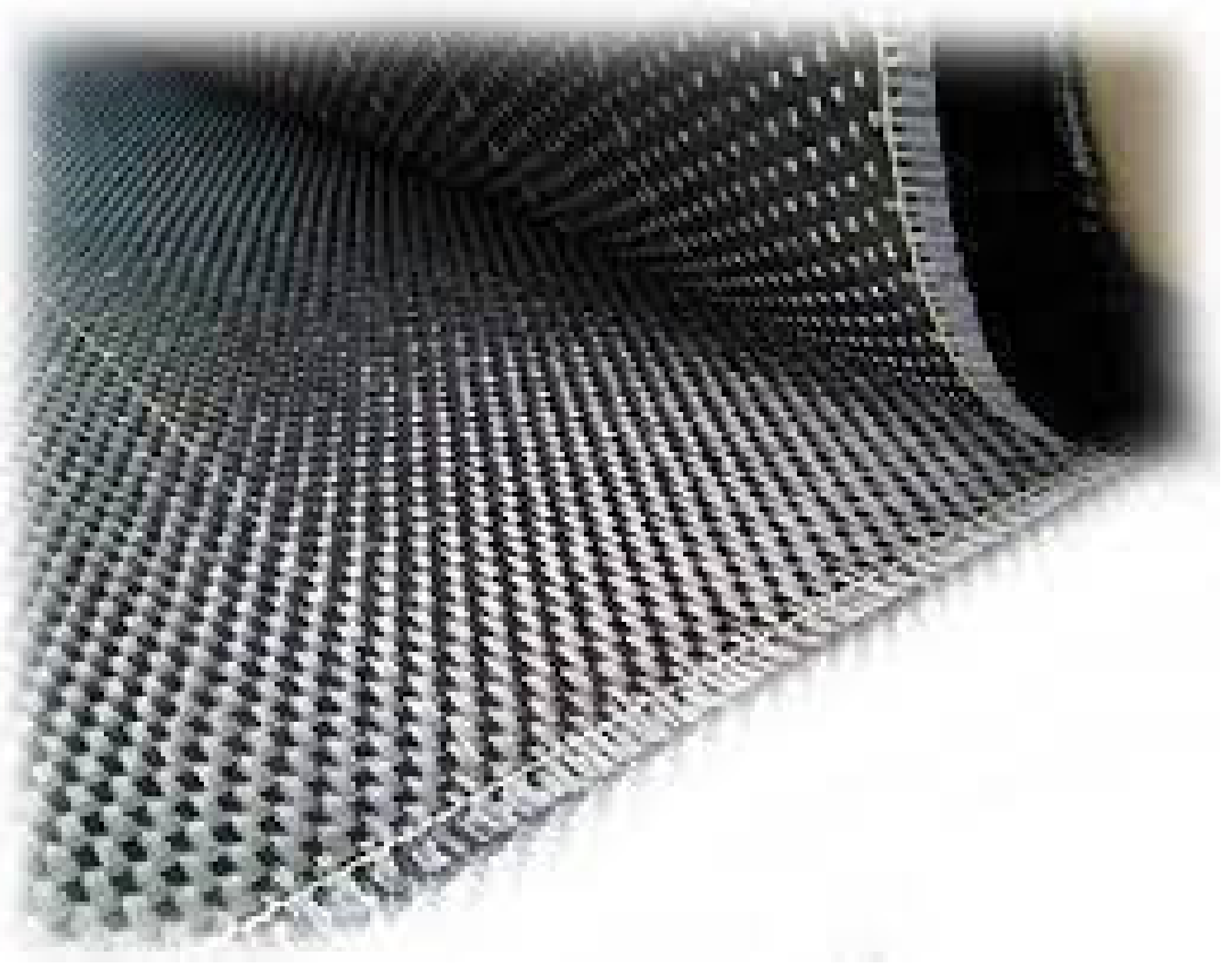
  • A fabric-reinforced bidirectional carbon mesh is designed to be field installed with a cementitious matrix to create an FRCM as a composite system for structural reinforcement applications. In particular, it makes beams and columns more flexible structurally. Epoxy (Ly556) and hardener (HY951) were employed in a ratio of 1 (hardener) to 4 to bond carbon fiber mesh to concrete (epoxy). Figure 1 depicts the carbon fiber mesh that was utilized in this work, and Table 2, Table 3 and Table 4 provide material parameters for concrete, carbon fiber mesh, and steel fibers that will be used in ABAQUS [30]. Table 5 displays the mix ratio and the material proportions.
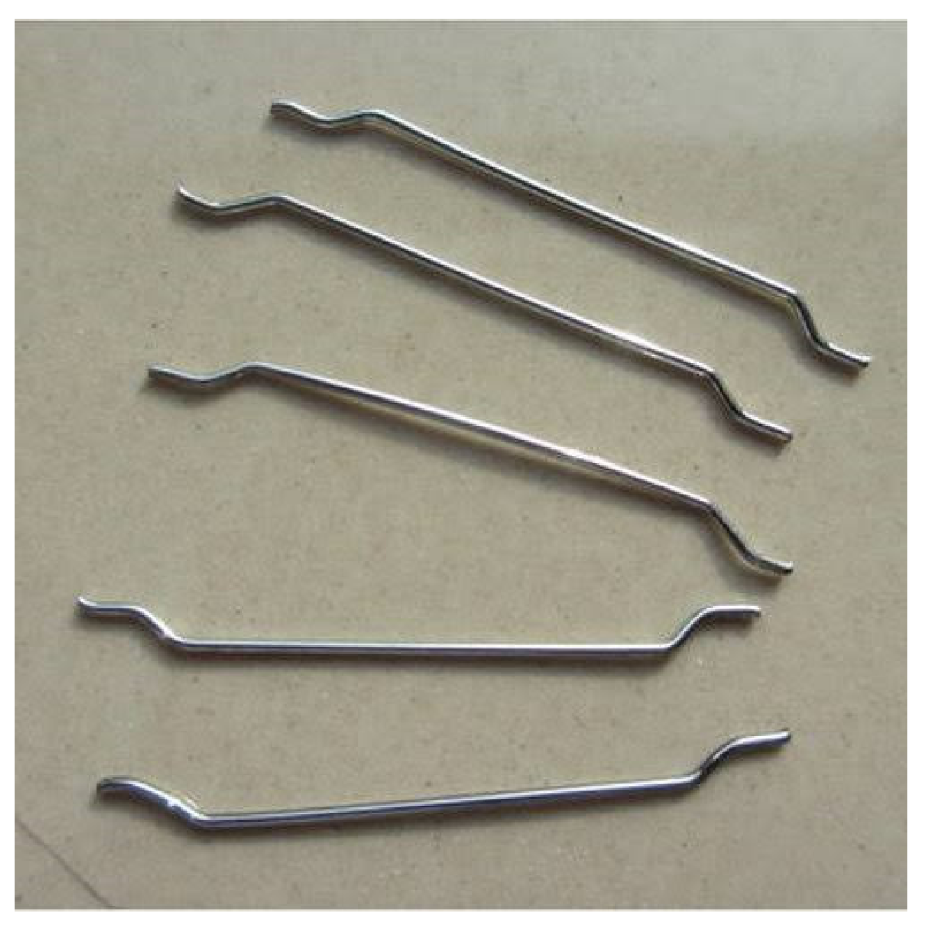
  • In this investigation, steel fiber with hooked ends was employed. The steel fiber with the hooked end was chosen among the many fiber kinds because, as was already explained, it is utilized to increase strength and offer additional anchoring in the concrete. The steel fiber utilized had a diameter of 0.50 mm and a length of 30 mm. The steel fiber utilized has a 60 aspect ratio. The steel fiber utilized in this investigation is seen in Figure 2.

3.2. Mix Proportions

For the target strength M25, the mix proportions chosen for the nominal mix with cement shown in Table 5. For each mix, 9 cubes of 150 mm are casted for the determination of compressive strength. Similarly, 9 cylinders of dimension 150 × 300 mm are casted for the determination of split tensile strength. Vibrators were used to mix, pour, and compress the concrete. The specimen was then taken out of the mold after 24 h and allowed to cure for 7, 14, and 28 days in a curing tank.

3.3. Specimen Details

A cube specimen of proportion 150 mm was made for conventional concrete and SFRC with a 1.5% dosage of the weight of concrete. The sample of the cube specimen cast is represented in Figure 3a. A cylinder specimen of diameter 150 × 300 mm was cast for conventional concrete and SFRC with a 1.5% fiber dosage of the weight of concrete. The sample of the cylinder specimen cast is represented in Figure 3b. A flexure beam specimen of size 500 × 100 × 100 mm was cast for both conventional and SFRC with a 1.5% fiber dosage weight of concrete. The sample the of beam specimen cast is represented in Figure 3c.

3.4. Beam Specimens

A reinforced concrete beam of size 1500 × 150 x× 150 mm was cast according to IS code (IS 456:2000) with reinforcements. Seven different beams are cast with varying parameters like plastic hinge length and carbon fiber mesh jacketing. Based on the mechanical properties of the conventional concrete and SFRC, a differentiation study was made. The steel fiber reinforced concrete with a fiber dosage of 1.5% of the total weight of the concrete shows increased mechanical properties than other fiber percentages. Hence, beams are cast with a 1.5% fiber dosage to the total weight of concrete. Researchers such as Baker, Sawyer, Corley, Mattock, Park, Pristley, Paulay, fradis, and panagiotakos expressions developed by them are used to calculate the lengths of plastic hinges on beams. Seven different beams are cast by varying their parameters as shown in Figure 4a conventional beam, Figure 4b carbon fiber mesh at the plastic hinge length of a conventional beam, Figure 4c carbon fiber mesh jacketing for the total length of a control beam, Figure 4d steel fiber reinforced concrete SFRC beam, Figure 4e SFRC only at the plastic hinge length (PHL) of a beam, Figure 4f SFRC and carbon fiber mesh jacketing at the plastic hinge length of a beam, and Figure 4g carbon fiber mesh (CFM) jacketing for total length with SFRC at the plastic hinge length of a beam, respectively.

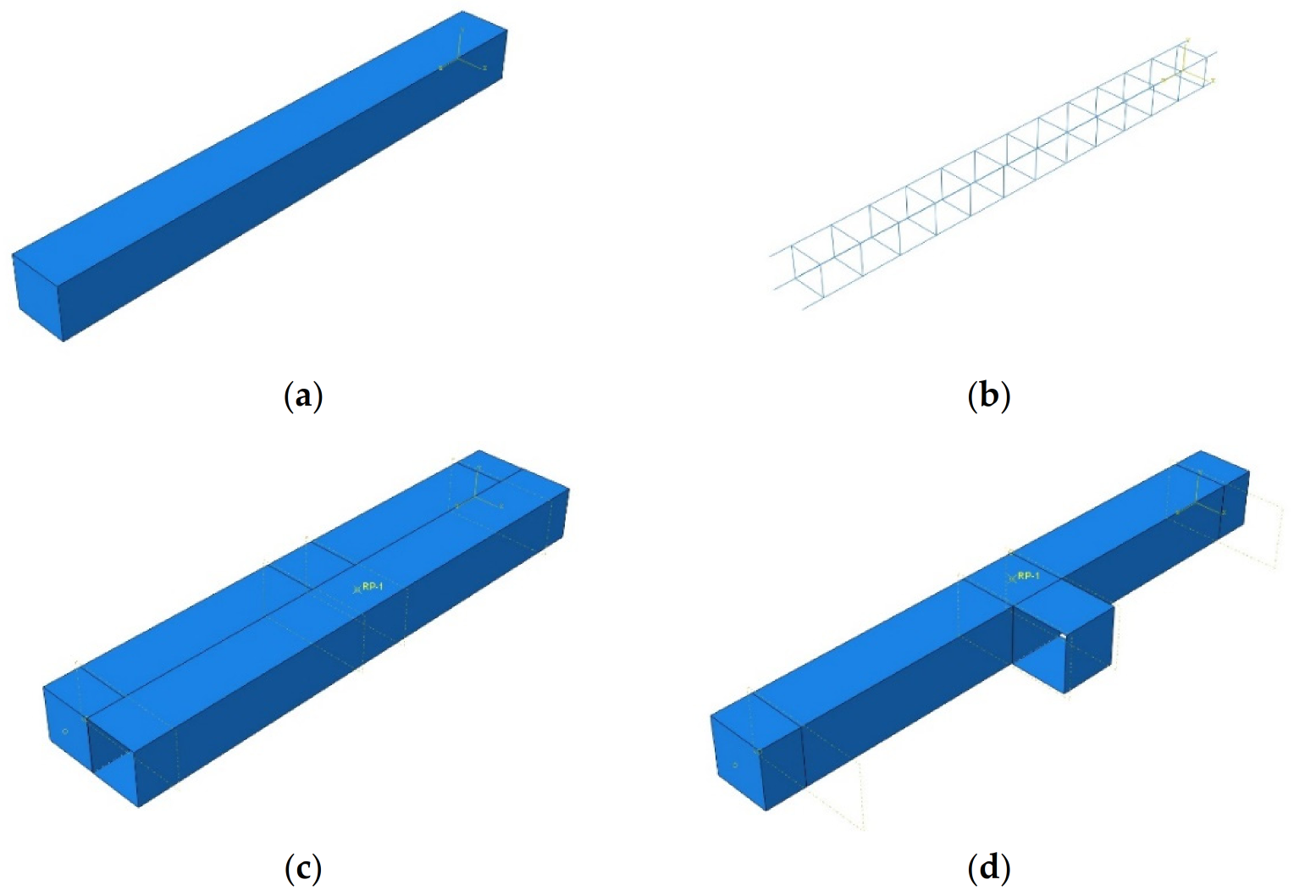
4. Analytical Investigation
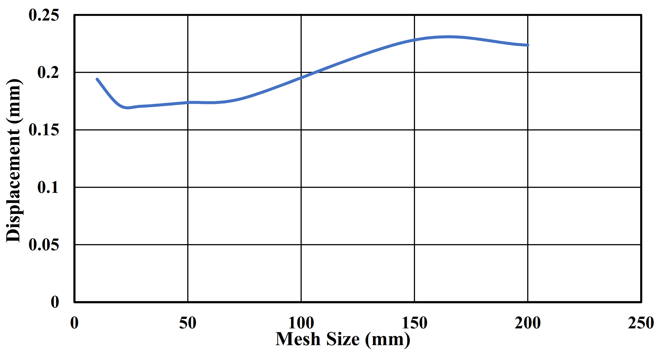
Figure 5 depicts the design of a 1500 mm span, 150 mm wide, and 150 mm deep beam using the standard finite element (FE) software ABAQUS, version 2020 [30]. The material properties of M25 for concrete and Fe415 for steel were applied. A carbon fiber jacketing technique was applied for the total length of a beam. The carbon fiber mesh model was created as a shell type. For the longitudinal reinforcement, 12 mm in diameter and stirrups of 8 mm in diameter were used. The reinforcement was placed with a cover provided with 25 mm on each side of a beam as shown in Figure 5. The concrete, reinforcement, and stirrups are given constraints of the embedded region for interaction with each other. The point load of 30 kN concentrated force and the boundary condition with both ends fixed are applied.

Convergence Study

The convergence study was analyzed by applying different mesh sizes with the same load. The mesh sizes of 200 mm, 150 mm, 100 mm, 75 mm, 50 mm, 40 mm, 30 mm, 20 mm, and 10 mm were applied and analyzed for convergence. By taking the results of load and displacement for each size, the convergence graph is drawn as shown in Figure 6. In the graph, when the linear pattern of the line moves, the value is noted. The linear pattern of line forms from 75 mm to 20 mm mesh size and the convergence value of 75 mm are chosen for the study.

5. Experimental Investigation

5.1. General

Concrete has the ability to bear compressive forces on its own. In this research work, cube specimens of 150 mm are cast to test crushing strength. The casting was performed for all of the combinations with varying steel fiber dosages. The cubes are cured for the period of seven, fourteen, and twenty-eight days, respectively. The cubes were examined in compression testing equipment after curing (CTM), as shown in Figure 7a. The split tensile strength of ordinary concrete was measured using cylinders measuring 150 × 300 mm. The cylinder was cured for 7, 14, and 28 days. The cylinders are examined in compression testing equipment after curing (CTM) as shown in Figure 7b. For determining the flexural strength of conventional concrete and SFRC, beams of size 500 × 100 × 100 mm were cast. The testing of the beam is done in the compression testing machine (CTM) after the curing period, as shown in Figure 7c.

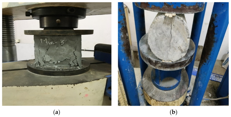
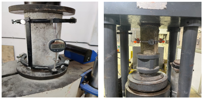
5.2. Modulus of Elasticity

The modulus of elasticity was calculated by applying uniaxial compression to the cylinder specimen and measuring the deformations with a dial gauge positioned between the 200 mm gauge length, as illustrated in Figure 8. The test was carried out using a compressometer in line with IS 516-1959 [31]. The cylinder specimens were installed on a compression testing equipment, and a consistent load was applied until the cylinder collapsed. The target load and deflection are taken into consideration.
The deflection values were determined as the strain value based on the length change. The strain is calculated by dividing the applied load by the cylinder’s cross-sectional area, and the stress is calculated by multiplying the dial gauge readings by the gauge length. The deformation of various loads was measured in order to compute the Young’s modulus of concrete for both the conventional and SFRC specimens. The findings are graphically displayed versus the tension. The computed modulus of elasticity for conventional concrete with SFRC is 25.47 N/mm2 and 29.025 N/mm2, as indicated in Table 6. Analytical modelling inputs are based on the outcomes of the test.

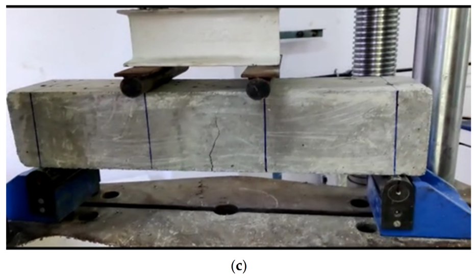
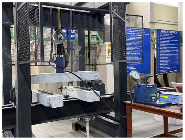
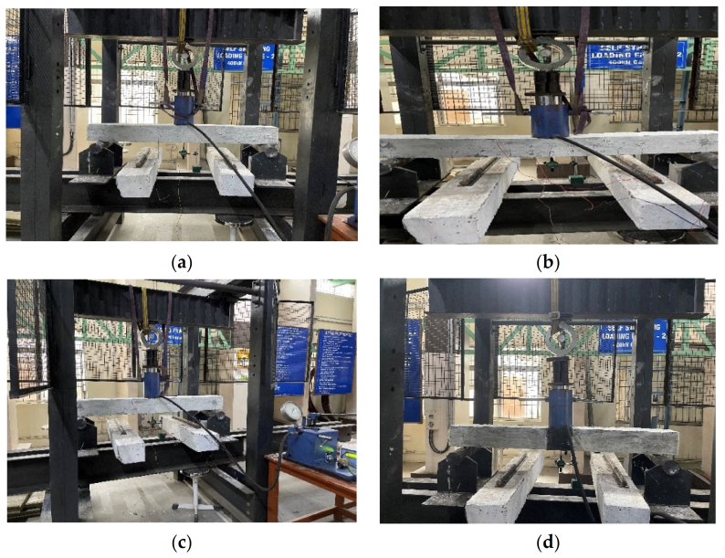
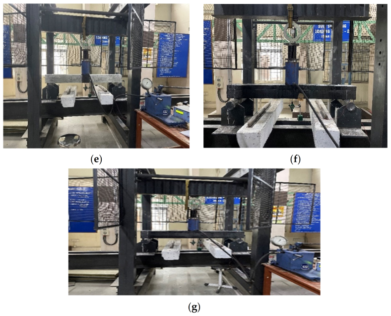
5.3. Monotonic Loading on Beams

The 200 kN load cell is fastened to the self-straining testing frame by a hydraulic jack, and the beam is hinged on both sides. As seen in Figure 9, the repeated loading is delivered at the middle of the beam’s top. To measure the deflection of the slab under loading until the final failure cracks occur, a mechanical dial gauge is mounted below the loading region of the beam.

6. Result and Discussion

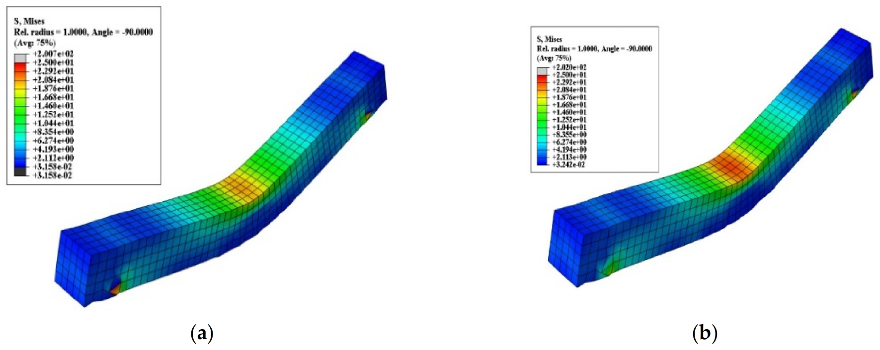
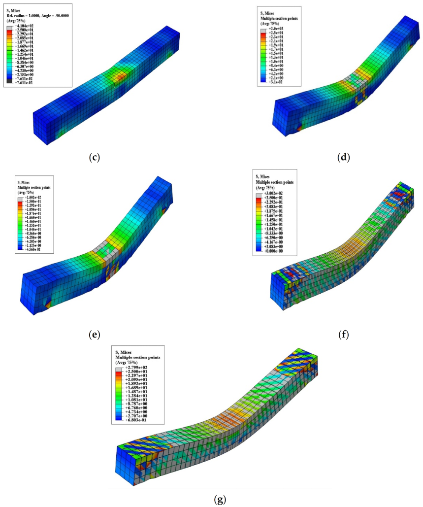
6.1. Stress and Deflection

The point load of a 30 kN concentrated force and with simply supported boundary conditions were applied. The mesh size of 75 mm was considered in the convergence study. A peak load of 40 kN with a deflection of 12 mm in the loading direction was achieved. From the analysis, the stress diagram is derived as mentioned in Figure 10. The maximum stress concentration is visible near the support and loading areas.
Carbon fiber mesh jacketing for the total length of the beam achieved a peak load of 90 kN with a deflection of 18 mm. Meanwhile, a peak load of 65 kN with a deflection of 18 mm was attained by the beam strengthened with carbon fiber mesh at the plastic hinge span location alone. Where the stress distribution evenly takes place throughout the span of the beam, jacketing is done throughout the span. However, the stress concentration is converging towards the mid-span.
The load was applied as displacement rotation and the boundary condition with simple support was applied. The mesh size of 30 mm was considered in the convergence study. From the analysis, the load-deflection graph is derived as shown in Figure 11.
The maximum load of 57 kN with a deflection of 18 mm was achieved for a beam reinforced with steel fiber throughout the span. Steel fiber reinforcement at the plastic hinge length of the beam achieved the maximum load of 45 kN with a deflection of 18 mm. At the same time, another set of beams are cast with SFRC and CFM together at the plastic hinge length of the beam, which shows the maximum load of 60 kN, and the last beam jacketed throughout the span with SFRC at the plastic hinge length achieved 92 kN. Hence, the beam jacketed throughout the span with carbon fiber mesh withstand the ultimate load of 64 kN due to the overall combined performance in reducing bending. Conventional RCC Beam shows 50 kN ultimate load and 45 kN load achieved by SFRC at plastic hinge length. Steel fiber at plastic hinge length with overall wrapping of carbon fiber mesh reached 11.58 mm the least deflection due to resistance to deflection which shows drastic change in stiffness. Conventional beam shows the maximum deflection if 17.8 mm due to the ultimate.

6.2. Experimental Results

The compression strengths of conventional concrete and SFRC for 7, 14, and 28 days are shown in Table 7. Where steel fiber reinforced concrete on 28 of days curing shows the maximum compressive strength of 31.2 N/mm2.
The split tensile strength of conventional concrete and SFRC for 7, 14, and 28 days is shown in Table 8. The tensile strength of concrete improved by 4.76 N/mm2 after 1.5% weight of steel fibers was added to the conventional concrete. Meanwhile, the flexural strength of concrete also improved to 5.1 N/mm2 on 28 days curing as mentioned in Table 9.
The Flexural strength of conventional concrete and SFRC for 7, 14, 28 days are shown in Table 9.

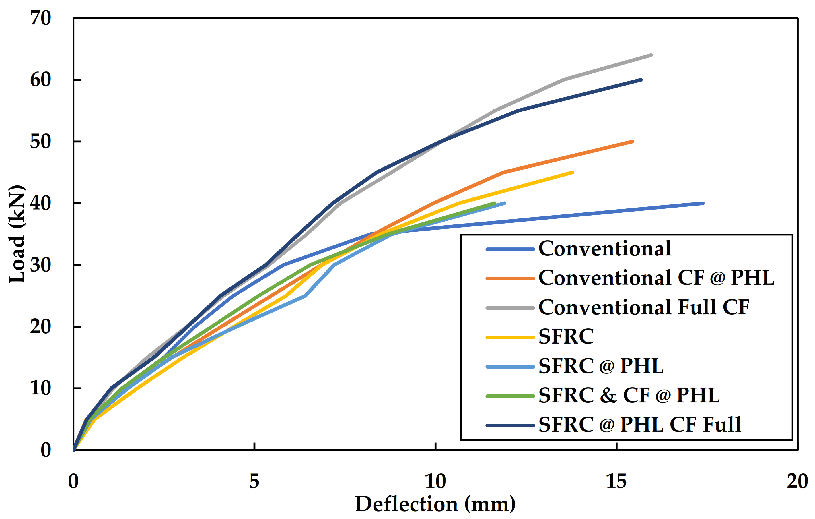
6.3. Ultimate Load and Deflection of Beams

The ultimate load and defection of the beam are determined by testing the beam with one-point loading as shown in Figure 12, and the ultimate load and deflection of the RCC beam are shown in Table 10. The ultimate load of 64 kN was attained by a beam where carbon fiber mesh jacketing was done for the full length. In the same way, the SFRC only at plastic hinge length and carbon fiber mesh jacketing for the total length of beam reached 60 kN. Conventional RCC beam and SFRC and carbon fiber mesh jacketing only in the zone of plastic hinge of a beam are in the same range as 38 kN. The deflection of the beam seems to be similar for SFRC only at plastic hinge length and SFRC and carbon fiber mesh jacketing only at plastic hinge length. Beams where carbon fiber mesh jacketing is used for strengthening show almost 15 mm of deflection. The comparison of all the above load and deflection data is mentioned in Figure 13 and Table 10.

6.4. Comparative Study on Analytical and Experimental Investigation
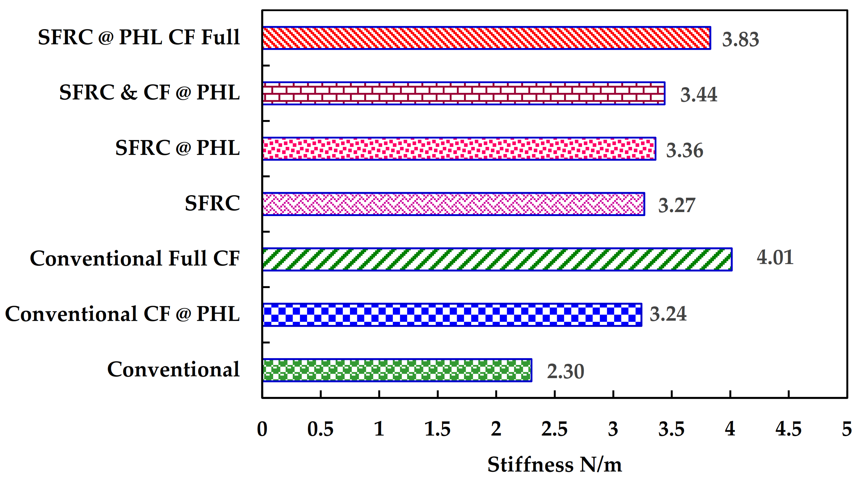
In this work, the displacement of the conventional beam, carbon fiber mesh jacketing for a full length, and carbon fiber mesh jacketing on the plastic hinge length of a beam for conventional, SFRC, and SFRC only at PHL are compared as shown in Table 11.
The experimental and analytical results were compared, which shows the deviation in results is nominal and in most cases, it’s almost similar.

6.5. Stiffness

The theoretical calculation of stiffness calculated by using l/250 of the beam as per IS 456:2000 is 6 mm. Figure 14 shows the difference in stiffness of different types of beam specimens under ultimate loading conditions, which helps to understand the role of the carbon fiber mesh and SFRC in providing strength to the beams from the experimental investigation.
The stiffness is calculated by the force-displacement relation and the stiffness is shown in Table 12. From the above results, SFRC only at PHL is stiffer when compared to conventional and SFRC. From the graph, it is obvious that among all the evaluated specimens, the steel fiber reinforcement at the plastic hinge length and the carbon fiber mesh jacketing along the complete span acquired the maximum stiffness.

7. Conclusions

The performance of a beam with steel fiber reinforcement along the length of the plastic hinge is presented in this analytical and experimental examination. After being cast and loaded monotonously, seven different beams’ mechanical characteristics are examined. These are the findings that were drawn from them.
  • Among different plastic hinge length expressions from Baker, Sawyer, Coreley, Mattock, Park, Pristley, Paulay, Fardis, and Panagiotakos, the Paulay and Pristley expressions have been considered for plastic hinge length calculations in experimental investigation.
  • Steel fiber reinforced concrete with a 1.5% content performs better in terms of compressive strength and split tensile strength when compared to regular concrete.
  • The split tensile strength of steel fiber-reinforced concrete seems to be 1.5 times larger than that of regular concrete due to the dispersion of steel fiber in the concrete, which influences the bonding and promotes tensile strength. The cylinder specimen was compressed using uniaxial compression in order to calculate the modulus of elasticity, and the results showed that the SFRC specimen with 1.5% steel fiber outperformed the conventional concrete specimen by a factor of 1.14. The same was thus used to casting beam specimens. The behavior under bending is clearly shown by the flexural strength test, which shows that the flexible beam with steel fiber exhibits a 1.39 times larger performance gain than that of a normal beam.
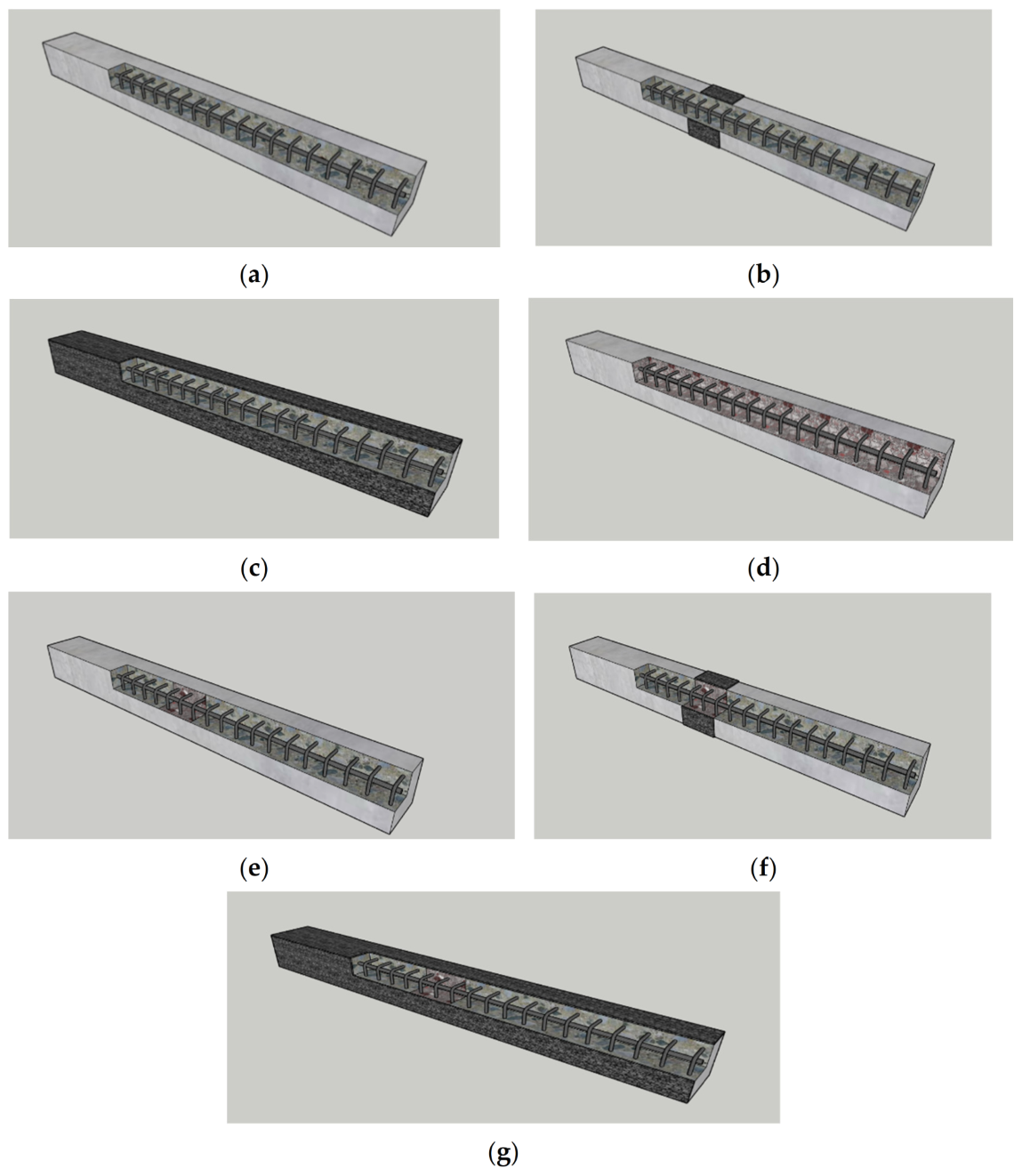
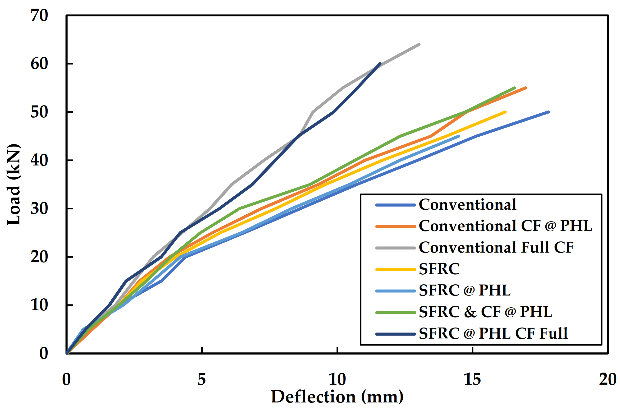
  • The results of conventional concrete, CFM jacketed on total length, CFM jacketed on PHL, SFRC, and SFRC at PHL, SFRC & CF at PHL, and SFRC at PHL & CFM jacketed on the total length of a beam were compared.
  • Steel fiber reinforcement in concrete has superior tensile strength and can withstand more severe loads than regular concrete when exposed to monotonic stress. Similar types of fracture patterns may be seen in steel fiber reinforced concrete with a 150 mm plastic hinge length and steel fiber dosed over the beam span. The failure happened simultaneously because of the material’s higher ductility. Cracks are appearing far from the zone of greatest deflection because of the steel fiber at the hinge length.
  • When compared to the RCC beam, the SFRC beam exhibits comparatively less deflection. The inclusion of SFRC at simply the length of the plastic hinge of a beam led to a similar discovery since steel fiber boosts the beam’s strength. Steel fiber reinforcement offers the same ductility and resilience to the load as SFRC and SFRC solely at PHL at a 150 mm plastic hinge length. When the traditional beam is reinforced across its span and steel fibres are used at the length of the plastic hinge, the total stiffness of the beam is fairly high. The ultimate load-bearing capacity and deflection due to delay in failure are both increased by carbon fiber mesh jacketing for the complete span with steel fiber dosage at the plastic hinge length.
  • Hence, from the above discussion two things are very clear, one is instead of providing steel fiber throughout the span of the beam, provide it at plastic hinge length alone as both of them provide the same performance under monotonic loading. This will reduce the number of fibers used for construction and which will be economical as well. Meanwhile, the next one is carbon fiber jacketing done for the whole beam span with fiber placed at plastic hinge length shows the best performance when compared to that of other techniques.

8. Scope for Future Work

Experiments with various types of fibers and with different percentages can be carried out to extend this work.

Author Contributions

P.S. Conceived the model, developed the empirical theorem, and conducted experiments. B.G.A.G., K.R. and P.S. I oversaw the research and the outcomes analysis. D.P.: Introduced monotonic loading as a concept in this project, constructed the slab, and produced the article. reviewed and submitted the work, worked on and oversaw the research. K.R. and B.G.A.G. The journal was recommended by K.R. and selected for submission. K.R., B.G.A.G. and K.R. Took part in the editing stage of the manuscript. All authors have read and agreed to the published version of the manuscript.

Funding

This research received no external funding.

Data Availability Statement

The data presented in this study are available on request from the corresponding author.

Conflicts of Interest

This manuscript has not been submitted to, nor is it under review by, another journal or other publishing venue. The authors have no affiliation with any organization with a direct or indirect financial interest in the subject matter discussed in the manuscript. The authors declare no conflict of interest.

References

  1. Barros, J.A.O.; Figueiras, J.A. Flexural Behavior of Steel Fiber Reinforced Concrete: Testing and Modelling. J. Mater. Civ. Eng. 1999, 11, 331–352. [Google Scholar] [CrossRef] [Green Version]
  2. Neto, B.N.M.; Barros, J.A.; Melo, G.S. A model for the prediction of the punching resistance of steel fibre reinforced concrete slabs centrically loaded. Constr. Build. Mater. 2013, 46, 211–223. [Google Scholar] [CrossRef] [Green Version]
  3. Sivanantham, P.; Gurupatham, B.G.A.; Roy, K.; Rajendiran, K.; Pugazhlendi, D. Plastic Hinge Length Mechanism of Steel-Fiber-Reinforced Concrete Slab under Repeated Loading. J. Compos. Sci. 2022, 6, 164. [Google Scholar] [CrossRef]
  4. Pradeep, S.; Vengai, V.E.; More, D.F. Experimental Investigation on the Usage of Steel Fibres and Carbon Fibre Mesh at Plastic Hinge Length of Slab. Mater. Today Proc. 2019, 14, 248–256. [Google Scholar] [CrossRef]
  5. Gopinath, A.; Nambiyanna, B.; Nakul, R.; Prabhakara, R. Parametric study on rotation and plastic hinge formation in RC beams. J. Civ. Eng. Technol. Res. 2014, 2, 393–401. [Google Scholar]
  6. Zhao, X.; Wu, Y.-F.; Leung, A.; Lam, H.F. Plastic hinge length in reinforced concrete flexural members. Procedia Eng. 2011, 14, 1266–1274. [Google Scholar] [CrossRef] [Green Version]
  7. Zhao, X.-M.; Wu, Y.-F.; Leung, A. Analyses of plastic hinge regions in reinforced concrete beams under monotonic loading. Eng. Struct. 2012, 34, 466–482. [Google Scholar] [CrossRef]
  8. Mainst, R.M. Measurement of the Distribution of Tensile and Bond Stresses Along Reinforcing Bars. ACI J. Proc. 1951, 48, 225–252. [Google Scholar] [CrossRef]
  9. Mattock, A.H. Rotational Capacity of Hinging Regions in Reinforced Concrete Beams, Flexural Mechanics of Reinforced Concrete. In Proceedings of the ASCE-ACI International Symposium, Miami, FL, USA, 10–12 November 1964; pp. 143–180. [Google Scholar]
  10. Sümer, Y. Determination of Plastic Hinge Length for RC Beams Designed with Different Failure Modes under Static Load. Acta Phys. Pol. A 2019, 135, 955–960. [Google Scholar] [CrossRef]
  11. Paulay, T.; Priestley, M.N. Seismic Design of Reinforced Concrete and Masonry Buildings; Wiley: New York, NY, USA, 1992; Volume 768. [Google Scholar]
  12. Holschemacher, K.; Mueller, T.; Ribakov, Y. Effect of steel fibres on mechanical properties of high-strength concrete. Mater. Des. 2010, 31, 2604–2615. [Google Scholar] [CrossRef]
  13. Khaloo, A.R.; Afshari, M. Flexural behaviour of small steel fibre reinforced concrete slabs. Cem. Concr. Compos. 2005, 27, 141–149. [Google Scholar] [CrossRef]
  14. Nguyen, N.T.; Bui, T.-T.; Bui, Q.-B. Fiber reinforced concrete for slabs without steel rebar reinforcement: Assessing the feasibility for 3D-printed individual houses. Case Stud. Constr. Mater. 2022, 16, e00950. [Google Scholar] [CrossRef]
  15. Xiang, D.; Liu, Y.; Gu, M.; Zou, X.; Xu, X. Flexural fatigue mechanism of steel-SFRC composite deck slabs subjected to hogging moments. Eng. Struct. 2022, 256, 114008. [Google Scholar] [CrossRef]
  16. McMahon, J.A.; Birely, A.C. Service performance of steel fiber reinforced concrete (SFRC) slabs. Eng. Struct. 2018, 168, 58–68. [Google Scholar] [CrossRef]
  17. Xiang, D.; Liu, S.; Li, Y.; Liu, Y. Improvement of flexural and cyclic performance of bridge deck slabs by utilizing steel fiber reinforced concrete (SFRC). Constr. Build. Mater. 2022, 329, 127184. [Google Scholar] [CrossRef]
  18. Paramasivam, P.; Ong, K.; Ong, B.; Lee, S. Performance of Repaired Reinforced Concrete Slabs under Static and Cyclic Loadings. Cem. Concr. Compos. 1995, 17, 37–45. [Google Scholar] [CrossRef]
  19. Laila, L.R.; Gurupatham, B.G.A.; Roy, K.; Lim, J.B.P. Effect of super absorbent polymer on microstructural and mechanical properties of concrete blends using granite pulver. Struct. Concr. 2020, 22, 1–18. [Google Scholar] [CrossRef]
  20. Laila, L.R.; Gurupatham, B.G.A.; Roy, K.; Lim, J.B.P. Influence of super absorbent polymer on mechanical, rheological, durability, and microstructural properties of self-compacting concrete using non-biodegradable granite pulver. Struct. Concr. 2020, 22, 1–24. [Google Scholar] [CrossRef]
  21. Kathavate, V.; Amudha, K.; Ramesh, N.; Ramadass, G. Failure Analysis of Composite Material under External Hydrostatic Pressure: A Nonlinear Approach. Mater. Today Proc. 2018, 5, 24299–24312. [Google Scholar] [CrossRef]
  22. Kathavate, V.S.; Pawar, D.N.; Adkine, A.S. Micromechanics-based approach for the effective estimation of the elastic properties of fiber-reinforced polymer matrix composite. J. Micromech. Mol. Phys. 2019, 4, 1950005. [Google Scholar] [CrossRef]
  23. Lowe, D.; Roy, K.; Das, R.; Clifton, C.G.; Lim, J.B. Full scale experiments on splitting behaviour of concrete slabs in steel concrete composite beams with shear stud connection. Structures 2020, 23, 126–138. [Google Scholar] [CrossRef]
  24. Madan, C.S.; Munuswamy, S.; Joanna, P.S.; Gurupatham, B.G.A.; Roy, K. Comparison of the Flexural Behavior of High-Volume Fly AshBased Concrete Slab Reinforced with GFRP Bars and Steel Bars. J. Compos. Sci. 2022, 6, 157. [Google Scholar] [CrossRef]
  25. Madan, C.S.; Panchapakesan, K.; Reddy, P.V.A.; Joanna, P.S.; Rooby, J.; Gurupatham, B.G.A.; Roy, K. Influence on the Flexural Behaviour of High-Volume Fly-Ash-Based Concrete Slab Reinforced with Sustainable Glass-Fibre-Reinforced Polymer Sheets. J. Compos. Sci. 2022, 6, 169. [Google Scholar] [CrossRef]
  26. Chinnasamy, Y.; Joanna, P.S.; Kothanda, K.; Gurupatham, B.G.A.; Roy, K. Behavior of Pultruded Glass-Fiber-Reinforced Polymer Beam-Columns Infilled with Engineered Cementitious Composites under Cyclic Loading. J. Compos. Sci. 2022, 6, 169. [Google Scholar] [CrossRef]
  27. IS 12269; Ordinary Portland Cement, 53 Grade-Specification. Bureau of Indian Standards: New Delhi, India, 1987; pp. 1–17.
  28. IS: 383; Specification for Coarse and Fine Aggregates from Natural Sources for Concrete. Bureau of Indian Standards: New Delhi, India, 1970; pp. 1–24.
  29. IS 456; Plain Concrete and Reinforced. Bureau of Indian Standards: New Delhi, India, 2000; pp. 1–114.
  30. SIMULIA. ABAQUS Standard User’s Manual, Version 6.14; Dassault Systèmes Simulia Corp.: Johnston, RI, USA, 2013. [Google Scholar]
  31. IS 516; Method of Tests for Strength of Concrete. Bureau of Indian Standards: New Delhi, India, 1959; pp. 1–30.
Figure 1. Carbon fiber mesh.
Jcs 06 00374 g001
Figure 2. Steel fiber.
Jcs 06 00374 g002
Figure 3. Test specimens (a) Cube specimens (b) Cylinder specimens (c) Flexure beam specimen.
Jcs 06 00374 g003
Figure 4. Schematic representation of beam specimens. (a) Conventional beam. (b) Conventional beam with CFM at PHL. (c) Conventional beam with CFM for full length. (d) Steel fiber reinforced concrete (SFRC). (e) SFRC only at PHL. (f) SFRC and CFM at PHL. (g) Carbon fiber mesh (CFM) jacketing for total length with SFRC at plastic hinge length.
Jcs 06 00374 g004
Figure 5. Details of the finite element model for RC beams. (a) Conventional beam. (b) Reinforcement details. (c) Beam with carbon fiber mesh jacketing for the total length. (d) Beam with carbon fiber mesh at plastic hinge length.
Jcs 06 00374 g005
Figure 6. Results of the convergence study.
Jcs 06 00374 g006
Figure 7. Testing of specimens. (a) Compressive strength test. (b) Tensile strength test. (c) Flexural strength test.
Jcs 06 00374 g007aJcs 06 00374 g007b
Figure 8. Compressometer test for lateral strain and linear strain measurements.
Jcs 06 00374 g008
Figure 9. Experimental setup for testing of beam.
Jcs 06 00374 g009
Figure 10. Stress Pattern- (a) Conventional Beam, (b) SFRC beam, (c) SFRC only at plastic hinge length of a beam, (d) Carbon fiber mesh jacketing at Plastic hinge length of a conventional beam, (e) SFRC and Carbon fiber mesh jacketing only at a plastic hinge length of a beam, (f) Carbon fiber mesh jacketing for a total length of a conventional beam, (g) Carbon fiber mesh jacketing for total length with SFRC at plastic hinge length.
Jcs 06 00374 g010aJcs 06 00374 g010b
Figure 11. Analytical load-deflection curve.
Jcs 06 00374 g011
Figure 12. Experimental setup (a) Conventional Beam, (b) SFRC beam, (c) SFRC only at plastic hinge length of a beam, (d) Carbon fiber mesh jacketing at plastic hinge length of a conventional beam, (e) SFRC and carbon fiber mesh jacketing only at a plastic hinge length of a beam, (f) Carbon fiber mesh jacketing for a total length of a conventional beam, (g) Carbon fiber mesh jacketing for total length with SFRC at plastic hinge length of a beam.
Jcs 06 00374 g012aJcs 06 00374 g012b
Figure 13. Load-deflection graphs from experiments.
Jcs 06 00374 g013
Figure 14. Stiffness of different RC beams.
Jcs 06 00374 g014
Table 1. Empirical formula to derive PHL.
DescriptionEmpirical Formula
Baker—1956k(z/d)1/4d
Herbert and Sawyer—19640.25d + 0.075z
Corley—19660.5d + 0.2√d(z/d)
Priestley and Park—19870.08z + 6db
Paulay and Priestley—19920.08z + 0.022db fy
Table 2. Concrete properties.
PropertiesConventional M25SFRC M25
Density2.3 × 10−92.3 × 10⁻⁹
Youngs Modulus (MPa)25,00029,025
Poisson Ratio0.20.2
Table 3. Carbon fiber mesh properties.
DescriptionProperties
Density1750 kg/m3
Young’s modulus of elasticity230,000 Mpa
Poisson’s Ratio0.3
Fiber weight200 g/m2
Tensile Strength2500 Mpa
Thickness0.048 mm
Table 4. Steel fibers properties.
DescriptionProperties
Density7.85 × 10−9
Young’s modulus of elasticity200,000 Mpa
Poisson’s Ratio0.3
Yield Stress450
Plastic Strain0.3
Geomentrylinear
Length30 mm
Diameter0.5 mm
Length/Diameter1/60
Table 5. Mix design.
ComponentQuantity (kg/m3)
Cement338.18
Fine Aggregate723.96
Coarse Aggregate1141.09
Water/cement0.55
Mix ratio1:2.14:3.37
Table 6. Modulus of elasticity of specimens.
S.NoSpecimenModulus of Elasticity (MPa)
1Conventional Plain Cement Concrete25.47
2Steel—Fiber Reinforced concrete29.03
Table 7. Compressive strength.
Concrete Type7 Days
(MPa)
14 Days
(MPa)
28 Days
(MPa)
Conventional16.320.526.59
SFRC 1.5%21.5825.8631.2
Table 8. Split tensile strength.
Concrete Type7 Days
(MPa)
14 Days
(MPa)
28 Days
(MPa)
Conventional2.543.613.9
SFRC 1.5%3.024.454.76
Table 9. Flexure strength.
Concrete Type7 Days
(MPa)
14 Days
(MPa)
28 Days
(MPa)
Conventional2.13.24.12
SFRC 1.5%2.923.95.1
Table 10. Ultimate load and defection of beams.
Beam DescriptionUltimate Load (KN)Deflection
(mm)
Conventional beam388.21
Carbon fiber mesh jacketing at plastic hinge length of conventional beam4815.43
Carbon fiber mesh jacketing for the full length of conventional beam6415.95
SFRC4313.78
SFRC only at the plastic hinge length of a beam4111.9
SFRC and carbon fiber mesh jacketing only at the plastic hinge length of a beam3811.63
SFRC only at plastic hinge length and carbon fiber mesh jacketing for a total length of a beam6015.67
Table 11. Comparative study of displacements predicted from the experiments against analytical predictions.
ModelExperimental DisplacementAnalytical Displacement
Conventional Beam5.88.6
Carbon fiber mesh jacketing for full length5.45.46
Carbon fiber mesh jacketing on plastic Hinge Length6.857.04
SFRC6.867.7
SFRC only at plastic hinge length7.28.32
SFRC and Carbon fiber mesh only at plastic hinge length6.546.39
SFRC only at plastic hinge length and carbon fiber mesh jacketing for full length5.315.5
Table 12. Stiffness of different RC beams.
ModelStiffness
(N/m)
Conventional beam2.30 × 106
Carbon fiber mesh jacketing for full length4.01 × 106
Carbon fiber mesh jacketing on PHL3.24 × 106
SFRC3.27 × 106
SFRC only at plastic hinge length3.36 × 106
SFRC and carbon fiber mesh only at plastic hinge length3.44 × 106
SFRC only at plastic hinge length and carbon fiber mesh jacketing for full length3.83 × 106
Publisher’s Note: MDPI stays neutral with regard to jurisdictional claims in published maps and institutional affiliations.

