1. Introduction
Additive Manufacturing (AM) is the most emerging plastic process that promises a single processing step to fabricate complex and multifunctional parts/products using CAD model [
1]. It is defined as a “Process of joining of material such as polymer, metal, concrete, ceramics, or rubber in the form of successive layers on top of each other” [
2]. Additive manufacturing, also known as 3D printing or rapid prototyping, has existed for many years. In 1984, the very first 3D printing technology was developed by Charles W. Hull of 3D Systems Corporation and named Stereo Lithography (SL), which was very expensive [
3]. Initially, rapid prototyping was mainly used by designers and architects because of its potential to make functional prototypes. Later, extensive research was done, and tremendous advancements were created. This led to the development of many other AM methods like fused deposition modeling (FDM), materials jetting, inkjet printing, powder bed fusion, etc. These advancements in AM have reduced its costs, productivity, and wastage and have increased printing quality, accessibility, sustainability, and user-friendliness [
3]. These improvements have amplified their usage in automotive, aviation, medical, construction, and other applications [
4].
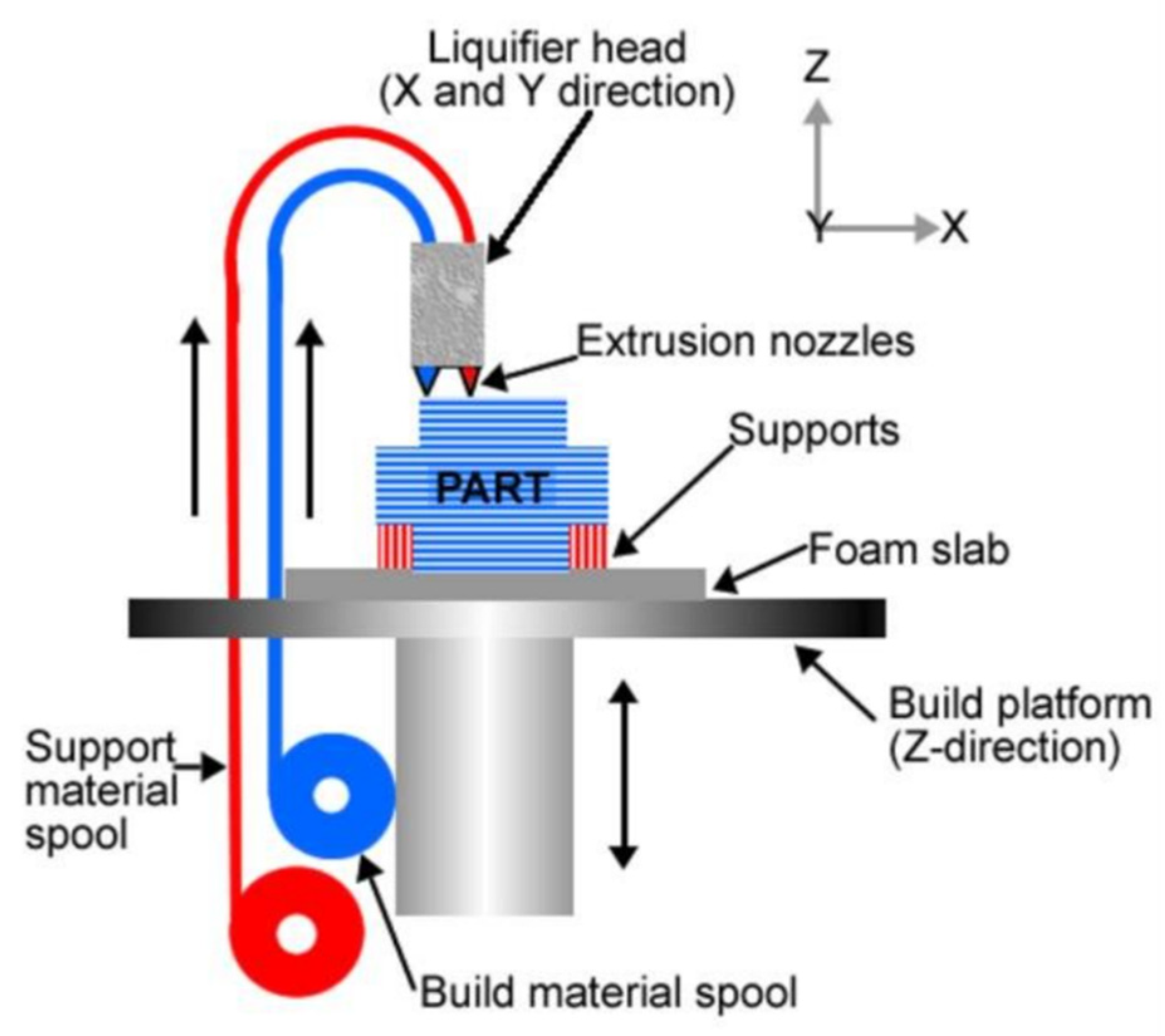
Among all AM techniques, FDM plays a dominant role in all kinds of industries from small-scale to large-scale due to its low cost and feasibility and can also be operated by individuals. FDM is a process in which a circular cross-sectional filament of predefined diameter is made to push into the hot-end through a feeder with a defined speed, and melted material is exited from the nozzle attached to the hot-end, it follows a defined path to construct a specimen layer-by-layer as depicted in
Figure 1.
The path and process parameters (printing patterns, infill density, infill angle, nozzle temperature, printing speed, etc.) can be given and controlled by a software called slicer [
5].
FDM is a cost-effective way to quickly produce prototypes and functional parts, aside from cheap machines and simple technological processes. By contrast, FDM parts have drawbacks in their mechanical properties. These parts possess the least dimensional accuracy and resolution among all other 3D printing technologies [
6]. Moreover, an FDM model’s parts have visible layer lines that require postprocessing to achieve a smooth, flat surface and less consistent behavior. Even though FDM rapid prototyping has a wide range of applications, it is not helpful to produce structural parts due to the anisotropic mechanical properties [
7]. This drawback restricts their usage in many applications.
At present, many research studies are aimed to increase the mechanical properties of 3D-printed parts. For instance, selecting significant printing parameters like infill density, infill pattern, extrusion temperature, nozzle diameter, layer thickness, raster angle, etc. are involved to increases their properties. Furthermore, research has been conducted regarding reinforcing the 3D-printed parts with both natural and artificial fibers (short fibers or long continuous fibers), but the results are not yet enticing enough for mainstream application [
5].
Research reveals that a typical FDM printer inserted into a nitrogen atmosphere to print parts shows a 30% increment in the tensile strength of its printed parts [
8]. Another research investigation specifies heat treatment of 3D-printed parts enhances adhesion between the interlayers and reduces internal stresses [
9]. However, an annealing process has constraints as some polymers are temperature-sensitive and leading to thermal shrinkage or warping.
One of our earlier studies dealt with post-treatment processing for better compaction of the polymer material processed by FDM. Before placing them in an autoclave at high pressure, mechanical testing was done on four different patterns with different infill densities and the best one was chosen for post-treatment. 3D-Printed PLA samples were placed in a customized autoclave at a temperature under the glass transition range, with a pressure of 50 bar exposed for 10 h.
The effect of pressure and temperature on 3D-printed samples was analyzed. In previous studies, the postprocessing treatment of 3D-printed and injection-molded specimens with autoclaving pressure and temperature treatment increased properties in all areas, including modulus and strength. This is because the samples’ internal tensions are released during the post-treatment process. In the autoclave, samples absorb moisture from hot compressed air in the autoclave, causing internal crystalline growth. The grain structure has been rearranged, resulting in a bigger grain structure. This helped with modulus and the development of strength. The combined effect of pressure and temperature, which relived internal stresses, increase in grain structure, enhanced their mechanical properties by approximately 20%, and the results were published [
10,
11,
12,
13,
14,
15,
16,
17,
18,
19,
20,
21,
22,
23,
24,
25,
26,
27].
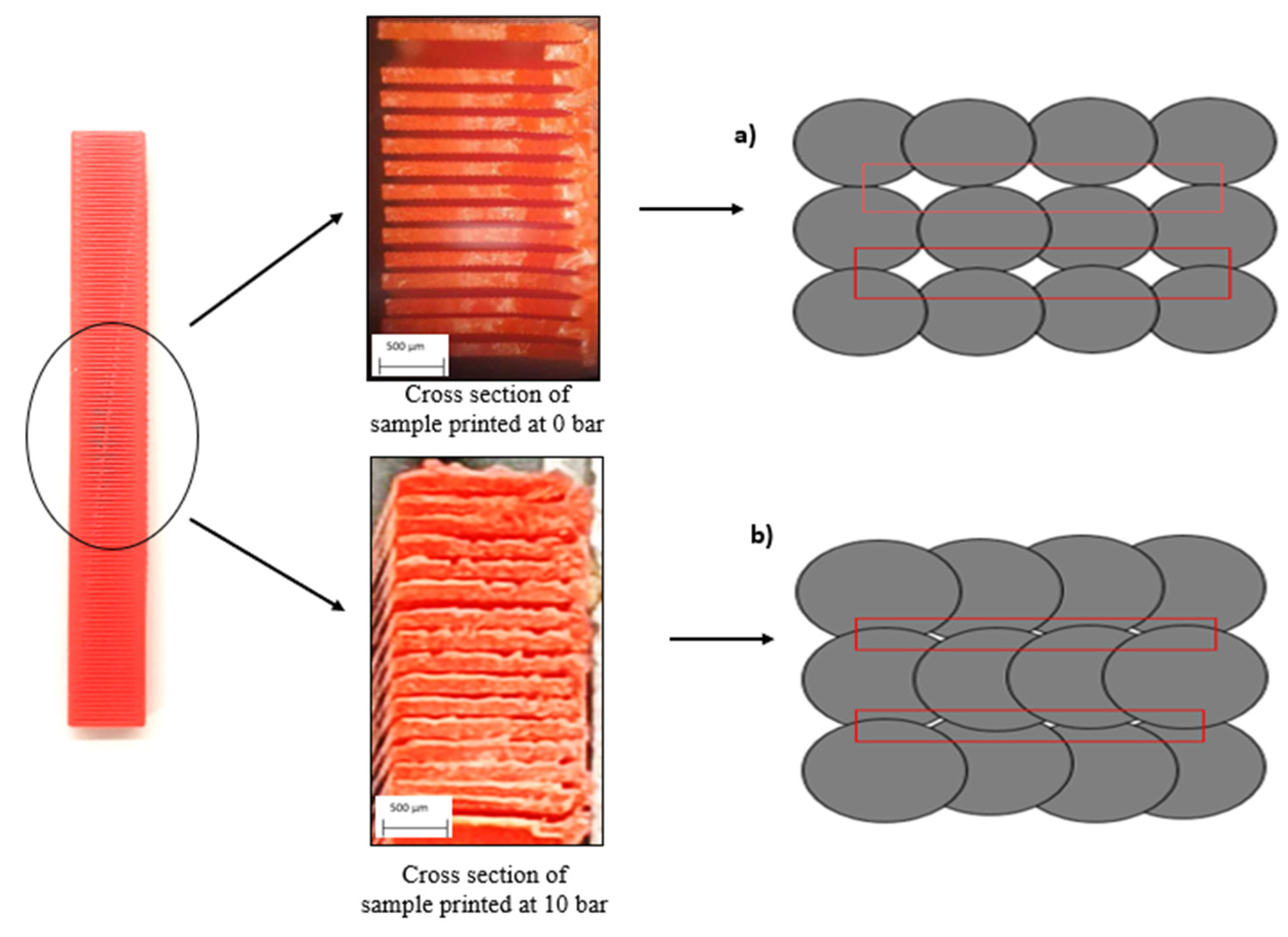
The 3D-printed samples were placed in an autoclave at temperatures less than or equal to the glass transition temperature; at this point, pressurization helped to prevent warping, improved the consolidation of layers, and nullified any voids. Tensile modulus was greatly increased. However, flexural and impact strength have low effect on the strength of the specimens. The weights also changed due to internal molecular rearrangement [
27].
Enrichment of mechanical properties of 3D-printed polymer parts also can be done by incorporating cellulose nanocrystals (CNCs) between adjacent layers of polymer with an aid of the atomization process. The sprayed CNCs acts as nano-stitches between printing layers, hence the ultimate strength and adhesion of layers boosts [
11].
Another proceeding is to improve the mechanical properties of 3D-printed parts by reinforcing them with other materials or fibers. Like PLA with carbon fibers, PETG with carbon fibers, though these are composite filaments are expensive when compared with neat PLA or neat PETG, but these materials are used in special applications with high loading capacities [
12].
Processing parameters like nozzle material, nozzle diameter, extrusion temperature, bed temperature, incoming materials whether they are neat or recycled, speed of a fan, etc. also affect the strength of parts printed by FDM. The printing direction affects the strength of printed parts as well.
In another research study, the SiC-coated PLA filaments used in the FDM process proved effective at augmenting the mechanical properties. SiC-coated PLA composites were printed and heated in the microwave, which enlarges the remelting of layers at 185 °C for 60 s; in this way, adhesion and consolidation of layers resulted in high strength [
13].
Inadequate adhesion between the deposited layer and the incoming extruding material while printing might be the reason behind the least attractive mechanical properties. This might be due to the temperature difference between the already deposited layers and incoming layers, as it relies on extruding the heated material and cooling [
14].
Another research reveals that 3D-printed FDM parts exhibit more enclosed voids as compared to injection molding composed parts amid pressure during the process and tight dimensional control [
15]. These voids are in conjunction with mechanical strength. The pressure plays a significant role in controlling the isotropic behavior of parts. The voids can be disciplined by downturns layer thickness and varying infill density. Though micro voids are available in such cases, which cannot be nullified completely.
Most researches were done to improve the surface quality of 3D-printed parts. Some postprocessing techniques like thermal treatment, chemical solution spraying, and coating of 3D-printed parts lead to more isotopically behavior which reduces the occurrence of voids and improves the consolidation of layers, and thus the mechanical properties.
However, there is no research work or mechanical setup created to integrate a 3D-printer inside a chamber and keep the complete process in a pressure and temperature environment. Pressure and temperature are the most important and imperative factors in almost all the processes to amplify the mechanical properties of 3D polymer-printed parts.
By considering results from previous research, this study aims to achieve high strength properties like the conventional method (injection molding) in 3D printing. This can be achieved by the strong bonding quality of interfaces between layers and preventing voids.
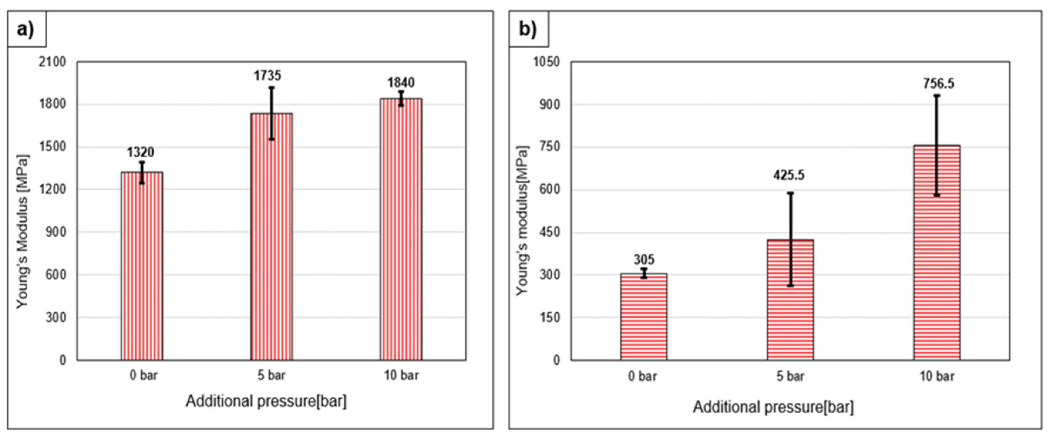
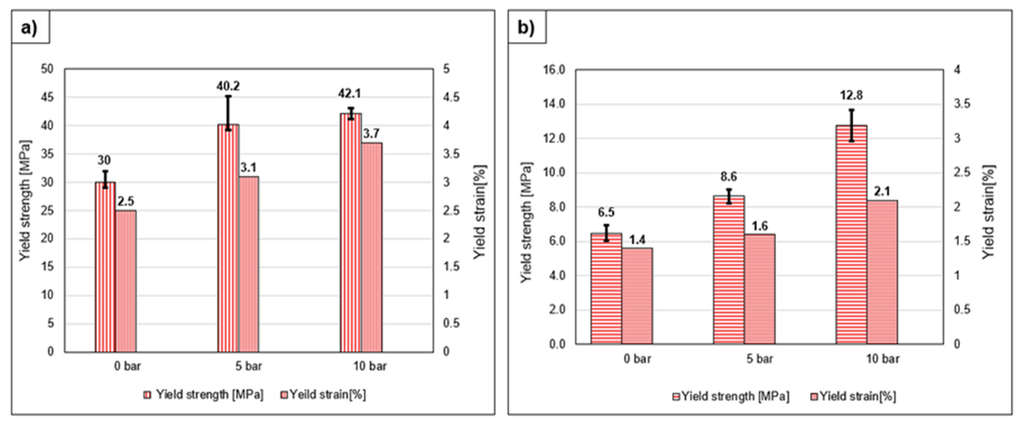
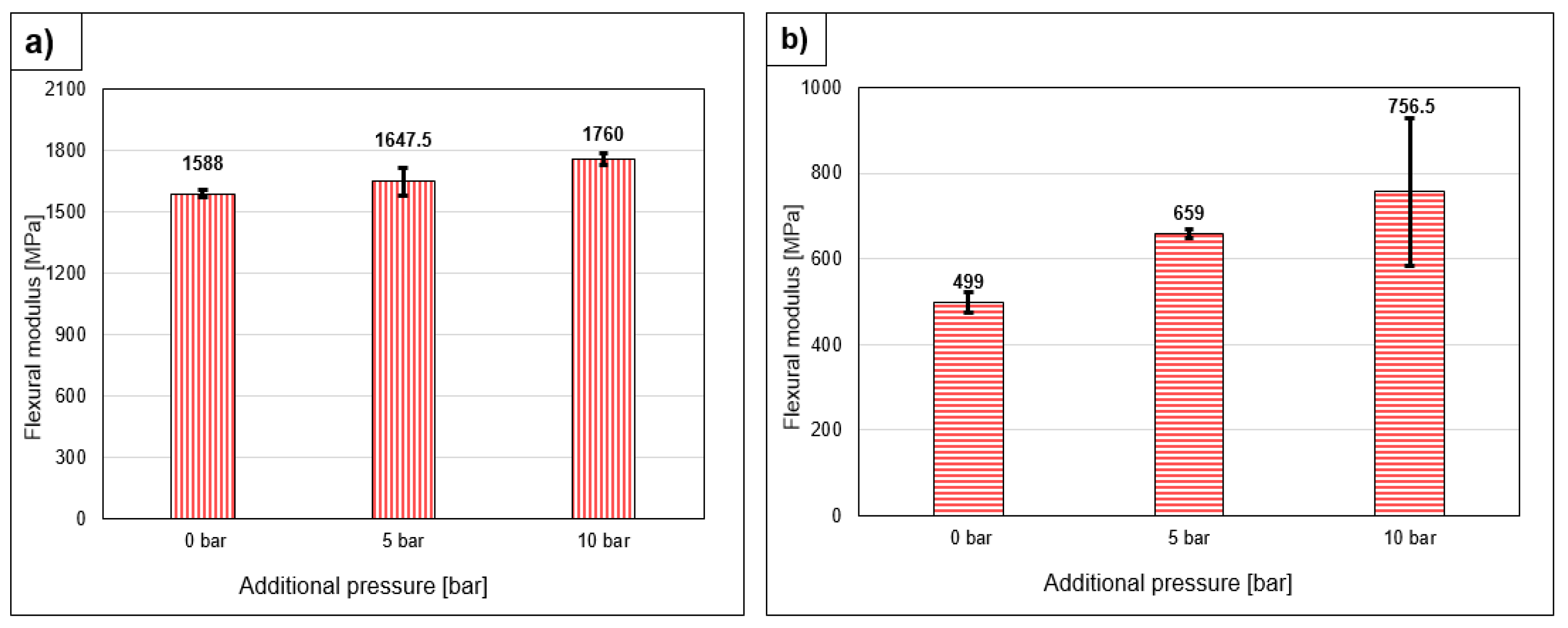
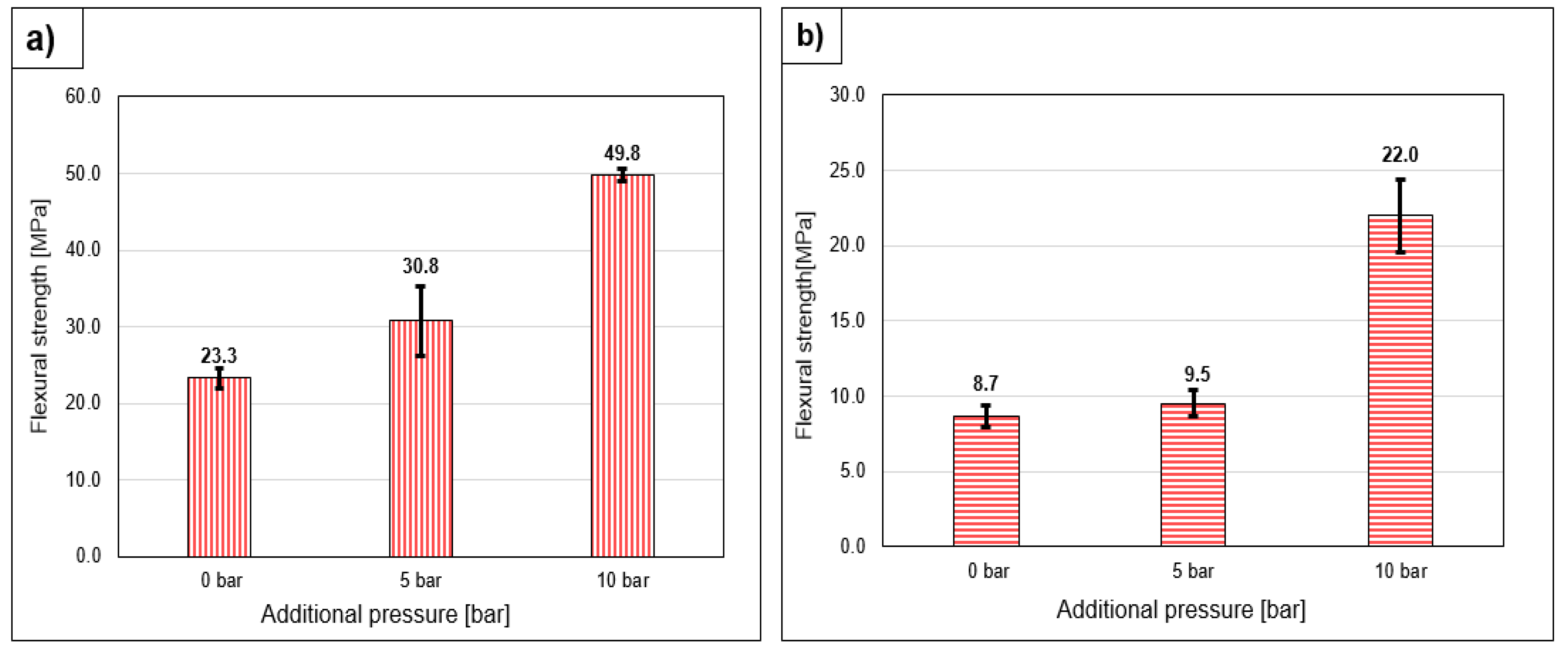
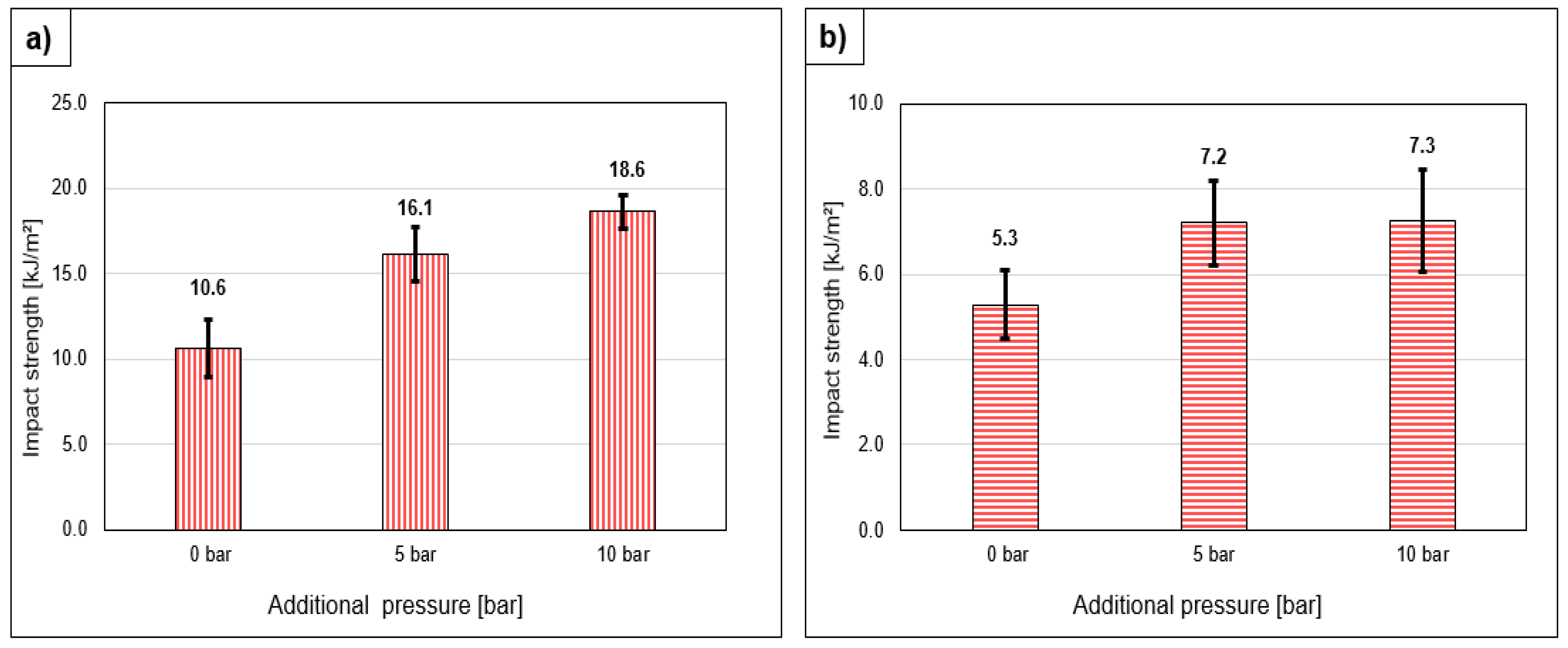
This research aims to 3D print specimens in a customized autoclave under the ambient pressure and elevated temperature conditions and to measure the improvement of mechanical properties such as yield strength, yield strain, Young’s modulus, flexural and impact strength. The samples were printed with the same infill density and same process parameters at 0 bar, 5 bar and 10 bar in the transverse and longitudinal directions to the hot-end nozzle. Every mechanical test was carried out with a sample batch. The results were averaged, analyzed and conclusions drawn.
2. Materials and Methods
2.1. Material
In this work, pure PLA (Polylactic Acid) filament (red in color) of high quality from Real Filament Company, Netherlands, was used. The cost of the filament is low, 25 € for 1 kg, and thus affordable. Usually, filaments are available in two sizes—1.75 mm and 2.85 mm diameter, but 1.75 mm diameter is most often used in FDM type 3D printers [
16].
PLA is a compostable polymer that degrades biologically (within days or months) under industrial composting conditions. It is extracted from renewable resources like corn starch or sugarcane. The use of PLA filaments in FDM is expected because of its low melting point (180–220 °C), and it supports quality surface prints, non-toxic, high UV resistance, and low moisture adsorption allows easy handling. Except for impact strength, mechanical properties (Young’s modulus, tensile strength, and flexural strength) of PLA are impressive compared to other polymers like polyethylene (PE), polypropylene (PP), polyamide (PA), polyethylene terephthalate (PET), and polystyrene (PS). With these advantages, it is used for quick prototyping [
17]. PLA limits its applications in thermally intensive parts because of its very low glass transition temperature, around 65 °C. Furthermore, it hampers the part/product because of its biodegradability.
2.2. Machines
2.2.1. FDM 3D-Printer
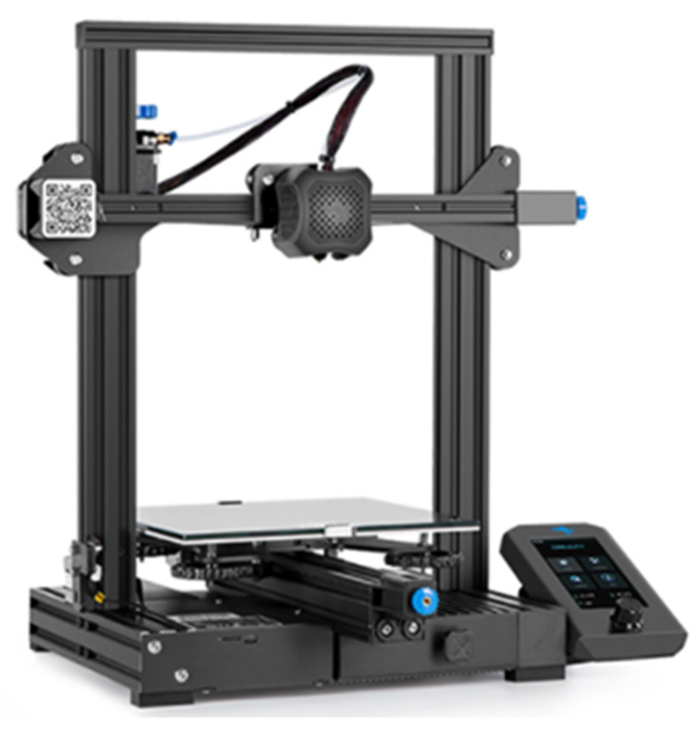
In this research, an Ender-3, V2 model FDM 3D-Printer from Creality 2020 was used (
Figure 2). The mechanical arrangement of axes is in order of Cartesian XZ-Head type for movement of extruder head and print-bed, i.e., extruder head moves in Xaxis and
Z-axis while print bed moves in the Y direction. The maximum possible dimensions are 220 × 220 × 250 mm (L × B × H), and the total weight of the machine is 7.8 kgs [
18]. General specifications like Maximum bed temperature, maximum extruder temperature, and maximum printing Speed are 100 °C, 250 °C, and 180 mm/s, respectively.
2.2.2. Autoclave
An autoclave is a machine commonly used for medical applications like disinfection and sterilization of medical instruments with elevated temperature and pressure conditions. Other than the medical industry, Autoclave expands its services in the chemical industry to vulcanize the rubber, post-treatment of coatings, and isothermal synthesis. Autoclaves used in industrial applications, especially in processing composites, either preprocessing or postprocessing, are known as industrial autoclaves or Composite Autoclaves [
19].
The industrial autoclaves play a dominant role in aeronautics and aerospace, multi-national companies like Airbus, space and defense, Comac, Foker GKN, and many other uses. They involve in processing parts of F1 cars and even in recent innovations like Electric Flying Taxis, chassis and accessories of the automotive industry, and ultralightweight components for helicopters and drone parts [
20,
21].
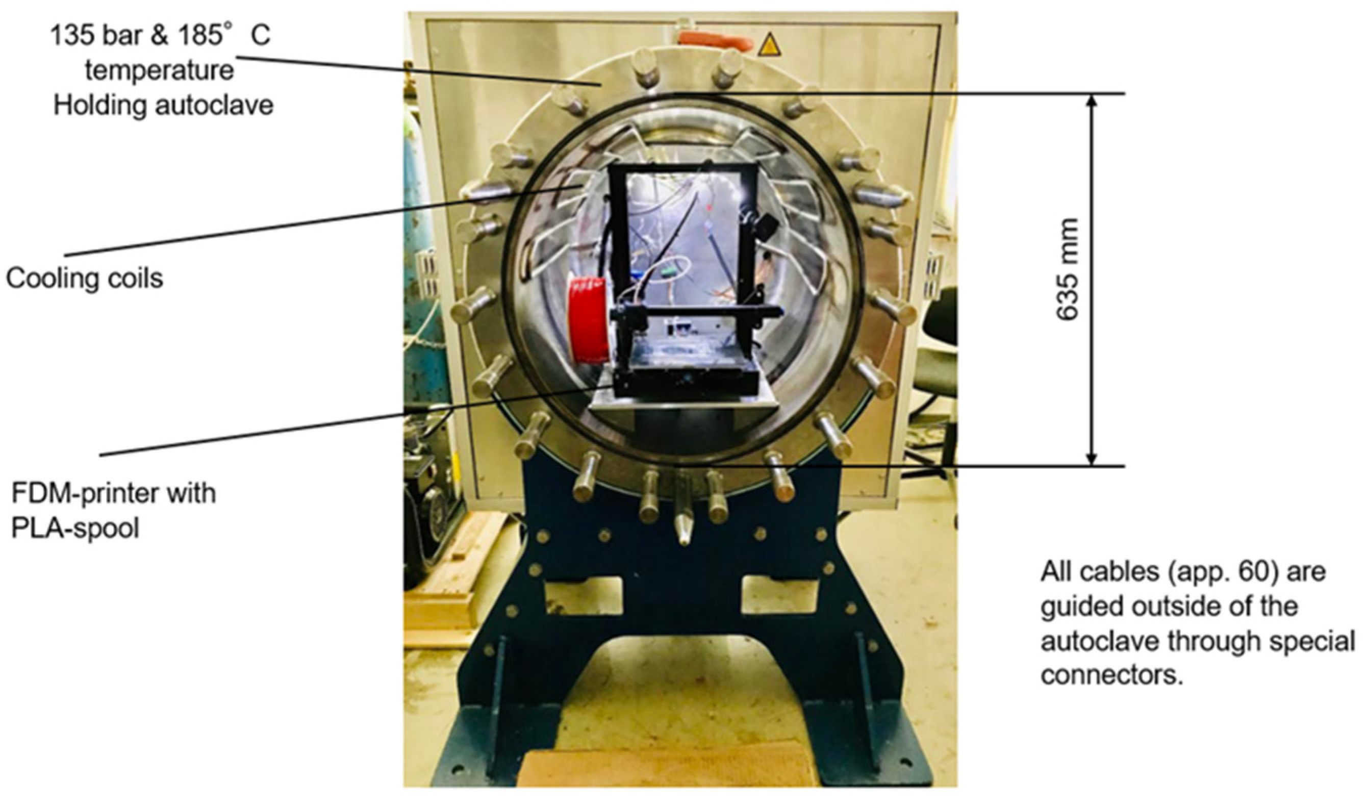
A customized autoclave chamber from Haage Anagram GmbH, Braunschweig, Germany, which had been specially designed to support polymer processing methods, was used in this research. This autoclave maintains a maximum of 135 bar and 185 °C and weighs ~1300 kgs (including a front lid with a weight of 300 kg). It controls the pressurization at an accurate rate with the aid of inlet and outlet valves. It has a direct heating system, i.e., in-built thermocouples around the cylindrical surface. The autoclave setup in the laboratory is illustrated in
Figure 3. The pressure and temperature inside the autoclave were measured using a sensor and displays their values on the monitor.
2.3. Fabrication of Specimens
To determine the bonding and the consolidation quality of layers of the 3D-printed part, specimens were printed under elevated temperature and pressure conditions in an autoclave. The testing specimens were designed in SolidWorks 2020 according to the testing standards, i.e., ISO 527 type 1A, which is in the shape of a dog bone, and DIN EN ISO 75 having a rectangular form. After designing the part, the file was saved in STL (Standard Triangle Language) file format since the slicing software reads only STL.
The necessary printing parameters were incorporated by using slicing software to generate a G-code that acts as a route map for the extruder to move in the given directions. For this research, a Prusa slicer was used.
Furthermore, the aligned rectilinear infill pattern was selected in two orientations, the infill angles 0° and 90°. Because in this pattern, more raster lines are available for better consolidation, it results in more advantageous for investigating mechanical consolidation of layers. The layer height of the specimens was 0.12 mm, and the print speed was set to 80 mm/min. As this Creality 3D-printer was manufactured to work in vacuum conditions and pressure conditions, some customization was done to fit it into the autoclave. The whole power supply unit was connected through an inbuilt connector through the autoclave wall at its rear side.
In addition, the control unit box of the 3D-printer was connected out of the autoclave using extended wires. The 3D printer was placed on a specially designed plate in the cylindrical cavity of the autoclave. An infrared night vision camera was installed inside the autoclave to record the video. Significant parts of the 3D printer did not withstand elevated pressure and temperature as it had not been made for such conditions. To evade these issues, some modifications were done to the hot end and electrical capacities of the 3D printer’s motherboard.
The testing specimens were printed at 0 bar, 5 bar, and 10 bar of additional pressure in the autoclave. As the material was PLA, the printing process was done with 205 °C nozzle temperature and 60 °C at the bedplate and the temperature was kept at 50 °C inside the autoclave while printing. Approximately 140 samples were printed for testing. For each test 7 to 8 samples were tested which were printed in two different printing patterns (longitudinal and transverse to the printing direction) in 3 different pressure conditions (0 bar, 5 bar and 10 bar) in autoclave. The test parameters including nozzle diameter, layer thickness, voltage capacities of printer, and sample printing environment conditions are shown in
Table 1.
2.4. Experimental Setup
The 3D printing was carried out in an autoclave. The pressure was built up inside the autoclave by sending compressed air into it using a compressor. The autoclave was integrated with a 3D printer as shown below in
Figure 3. In this research work, different mechanical tests like tensile, flexural, and Charpy impact were conducted on the printed samples, and, based on tests results, conclusions were drawn.
2.5. Electrical Alterations of the 3D-Printer
CrealiEnder3 V2 is powered with a V4.2.2 motherboard, which works with TMC2208 stepper drivers. It is charged with the 24 V DC power from the Power Supply Unit (PSU). Under pressurized conditions above 2 bar in the autoclave, the printer stopped either by thermal runaway or homing failed errors. To minimize these errors, the DC power input to the motherboard had been increased to 25 Volts by the potentiometer in the PSU. However, it could not sustain the elevated pressure and stopped repeatedly.
Even upon various voltage iterations, i.e., 25.3 V, 25.6 V, and 25.9 V, the printer could not run, and any further voltage may strain the PSU unit, thus decided for other possible modifications. Therefore, the old V4.2.2, with the sophisticated and advanced in its class V4.2.7 silent motherboard, which comes with TMC2225 stepper drivers and draws the same 24 V DC power, was upgraded. The stepper drivers’ default Vref values (X-1.17 V, Y-1.16 V, Z-1.16 V, Z-1.36 V) cannot print smoothly under pressure, so power should be hiked for the stepper drivers of the stepper motors. The 4 stepper drivers are equipped with individual potentiometers and can be modified to calculated higher Vref values. By multiple iterations, these values (X-1.20 V, Y-1.19 V, Z-1.19 V, and Z-1.39 V) work great with 5 bar pressure, and more could be possible.
2.6. Material Tests
2.6.1. Tensile Test
The tensile strength, stiffness, and elongation properties were measured according to EN ISO 527, using a tensile testing machine from Zwick (Proline Z005) along with Zwick’s Test Expert software. The strain measurement was done optically with the VideoXtens-system also from Zwick.
A batch of five samples was tested for every printing environment condition; the results were averaged to find the properties. Before starting each test, the external force on the testing machine should be maintained at zero.
2.6.2. Flexural Test
Flexural properties of materials are defined through the 3-point bending test according to DIN EN ISO 178 using the Zwick -UTM mentioned previously.
2.6.3. Charpy Impact Test
The Charpy impact test according to DIN ISO 179) is a measurement for the impact strength, considering the amount of energy that is absorbed by a material subjected to an impacting force. The impact test was carried out with a RayRan pendulum with an impact energy of 4 joules and an impact velocity of 2.9 m/s. Furthermore, a notched specimen is used to measure the impact resistance of a cracked material. It is a destructive testing method [
21]. This testing process involves striking a testing sample with a hammer on the pendulum arm while the sample is held in a fixed position. If the test is done on a notched sample, the hammer must strike on the opposite side of the notch. It is measured in units kJ/m
2. Quality assurance between materials is done based on a standardized Charpy impact test [
22].


