Article

Mechanical Properties of a Biocomposite Based on Carbon Nanotube and Graphene Nanoplatelet Reinforced Polymers: Analytical and Numerical Study

1
LPMAT Laboratory, FSAC, Hassan II University, Casablanca 20100, Morocco
2
REMTEX Laboratory, ESITH, Casablanca 20000, Morocco
3
LEM3-UMR 7239 CNRS, Arts et Métiers ParisTech Metz, 57070 Metz, France
4
IRDL, UMR-CNRS 6027, ENSTA Bretagne, 29806 Brest, France
5
LN2 Laboratory, CNRS, Sherbrooke University, Sherbrooke, QC J1K 0A5, Canada
*
Author to whom correspondence should be addressed.
J. Compos. Sci. 2021, 5(9), 234; https://doi.org/10.3390/jcs5090234
Submission received: 31 July 2021 / Revised: 21 August 2021 / Accepted: 30 August 2021 / Published: 3 September 2021
(This article belongs to the Special Issue Carbon-Based Polymer Nanocomposites)

Abstract

:
Biocomposites based on thermoplastic polymers and natural fibers have recently been used in wind turbine blades, to replace non-biodegradable materials. In addition, carbon nanofillers, including carbon nanotubes (CNTs) and graphene nanoplatelets (GNPs), are being implemented to enhance the mechanical performance of composites. In this work, the Mori–Tanaka approach is used for homogenization of a polymer matrix reinforced by CNT and GNP nanofillers for the first homogenization, and then, for the second homogenization, the effective matrix was used with alfa and E-glass isotropic fibers. The objective is to study the influence of the volume fraction V f and aspect ratio AR of nanofillers on the elastic properties of the composite. The inclusions are considered in a unidirectional and random orientation by using a computational method by Digimat-MF/FE and analytical approaches by Chamis, Hashin–Rosen and Halpin–Tsai. The results show that CNT- and GNP-reinforced nanocomposites have better performance than those without reinforcement. Additionally, by increasing the volume fraction and aspect ratio of nanofillers, Young’s modulus E increases and Poisson’s ratio ν decreases. In addition, the composites have enhanced mechanical characteristics in the longitudinal orientation for CNT- reinforced polymer and in the transversal orientation for GNP-reinforced polymer.

1. Introduction

The future materials used in turbine blades for wind or marine energy are mainly focused on the use of lighter materials with enhanced mechanical properties and low cost [1,2,3,4]. In the field of modern wind energy, the use of biocomposites is a sustainable solution, especially for small blades [5,6,7,8,9,10]. On the other hand, most blades are disposed of in landfills, provoking environmental issues since the blades are made from non-biodegradable fibers like glass and carbon [11,12,13]. Natural fibers and biodegradable polymers are biocomposite materials. Natural fibers like alfa, sisal, hemp and flax fibers have low cost and low density with high strength, and are non-abrasive, biodegradable and eco-friendly compared to glass/carbon fibers [14,15]. For the matrix, thermoplastic material is an emerging type, and is relatively cheap and eco-friendly. However, thermoplastic composites also have higher stiffness and fatigue strength [16]. The use of CNTs and GNPs provided enhanced mechanical properties of materials, which resulted in higher fatigue resistance, shear strength and fracture toughness compared to the conventional composites reinforced by microscale materials [17,18,19,20,21]. One of the benefits of reinforced composite materials with nanofillers is their ability to avoid micro-cracking progression and provide improved transverse shear distribution to minimize delamination failure [22]. CNTs may be dispersed in polymer resin or deposited on fiber surfaces to improve their interfacial interactions between the matrix and the fibers [23,24]. CNTs and GNPs have a large specific surface area, which leads to good interfacial adhesion with the matrix and a small weight fraction can dramatically change their mechanical [25,26,27,28,29,30], thermal [31,32,33] and electrical [34] properties. Certain challenges can be overcome during the manufacturing process of nanocomposites, especially in the dispersion and functionalization of nanofillers. The large surface area/volume ratio of CNTs results in van der Waals attractive forces that cause excessive nanofiller agglomeration. Due to the extreme non-uniform dispersion and weak bonding at the interfaces, this tendency of the nanofillers to agglomerate degrades the mechanical properties of the nanocomposites. While nanoscale experimental research is still a growing field, computational modeling techniques are the best way to investigate the impact of such parameters. In order to characterize nanocomposites with atomic to micromechanical methods, several analytical and computational models have been developed for this purpose [35,36,37,38,39,40,41]. Many micromechanical homogenization approaches based on CNT and GNP nanocomposites are used to study their mechanical, electrical and thermal properties, as discussed in some review articles [25,27,28,29,30].
Ramanathan et al. [42] studied functionalized graphene sheets at 0.05 wt% embedded in PMMA polymer, with an increase in Young’s modulus by 33%. In addition, in the study of Das et al. [43], only 0.6% of functionalized graphene layers can significantly enhance the Young’s modulus of PVA and PMMA polymers. Thostenson et al. [44] studied MWCNT-reinforced polystyrene composite by using the Halpin–Tsai model, and the elastic modulus composite was predicted and compared with experimental results. It was shown that when the diameter of carbon nanotubes increases, the mechanical performances of the composite improved significantly. In Hu et al.’s [45] study, molecular and computational structural mechanics were used to analyze the mechanical deformation of an RVE representing a carbon nanotube-reinforced composite. The stiffness of the interface and RVE geometry were investigated and, with a volume fraction between 0.48 and 2.75%, the reinforcement can increase by 10 to 70% in the length direction of the nanotube. Shi et al. [46] studied the effects of carbon nanotube waviness and their agglomeration in polymer-reinforced composite by using a novel method, the orientations considered are aligned and random and the analysis was evaluated by Eshelby–Mori–Tanaka theory. Zhong et al. [47] presented a finite element analysis of a unidirectional flax fiber/polypropylene composite with Hashin criteria failure damage. This computational mechanical prediction had very consistent results with an experimental study.
Jespersen et al. [48] investigated a computational study of disc-shaped and fiber reinforcements embedded in polyurethane coatings. They showed high performance in improving the anti-erosion protection of wind turbine blades. Doagou-Rad et al. [49] examined a computational and Mori–Tanaka analytical study of CNT- and GNP-reinforced composite with finite element and molecular dynamic analysis. Three orientations were taken into account, aligned, random and wavy inclusions. The results demonstrate that curved random fibers deteriorate the elastic performance of nanocomposite. Pontefisso et al. [50] studied the restacking graphene sheet effect, which enhances interphase and hardiness properties of nanocomposites. Additionally, when the graphene nanoplatelets cause crack deviation at early stages, CNTs maintain debonding bridges between the fibers and matrix after the crack is created. Dai et al. [51] showed that by increasing the volume fraction, aspect ratio and interface mechanical characteristics, Young’s modulus can be improved. On the other hand, Young’s modulus decreases with several parameters: clustering, crumpling and misalignment of graphene sheets. Thus, random graphene sheets reduce Young’s modulus in comparison to aligned graphene sheets. Dai et al. [52] report that carbon/glass hybrid reinforcement by aligned CNTs increases the composite fatigue performance under cyclic mechanical and environmental loading. Many works used functionally graded CNT nanofillers to improve the vibratory structural response of a conical composite shell [53,54,55]. Sobhani et al. [56] evaluated the properties of homogenized composite by using the rule of mixture method.
In this study, a biocomposite based on polypropylene PP and alfa fibers has been simulated and compared with unsaturated polyester UP and E-glass fiber. The novelty is the reinforcement of the polymer with CNT and GNP nanofillers in order to have improved thermomechanical properties of composites used in wind turbine blades. The polymers reinforced with nanofillers have a higher strength to mass ratio, and they have been used to reinforce the structure, specifically in the areas of the blade where there is a high mechanical load [57]. They have also been utilized to improve thermal performance on the exterior blade surface for deicing in cold areas [58]. In this paper, we also propose a procedure allowing the evaluation of the properties of a multiphase composite by a multiscale homogenization procedure. There are two computational tools used based on Mori–Tanaka theory: Digimat-MF is a mean field homogenization module to define composite behavior as a function of volume fraction, shape, size and orientation of inclusions; Digimat-FE is a finite element module used to generate realistic microstructures as a representative volume element RVE. The RVE is the smallest volume of a composite which represents the behavior of the whole composite. In the 1st homogenization of CNT/GNP in polymer, the analytical Mori–Tanaka approach [59,60] is utilized and validated with computational Digimat-MF/FE. Additionally, in the 2nd homogenization of hybrid polymer with fibers, analytical methods are employed: Mori–Tanaka, Chamis [61], Hashin–Rosen [62] and Halpin–Tsai [63,64], and validated with Digimat-MF/FE. The flowchart of the main homogenization procedure is shown in Figure 1. All analytical models are implemented in Matlab.

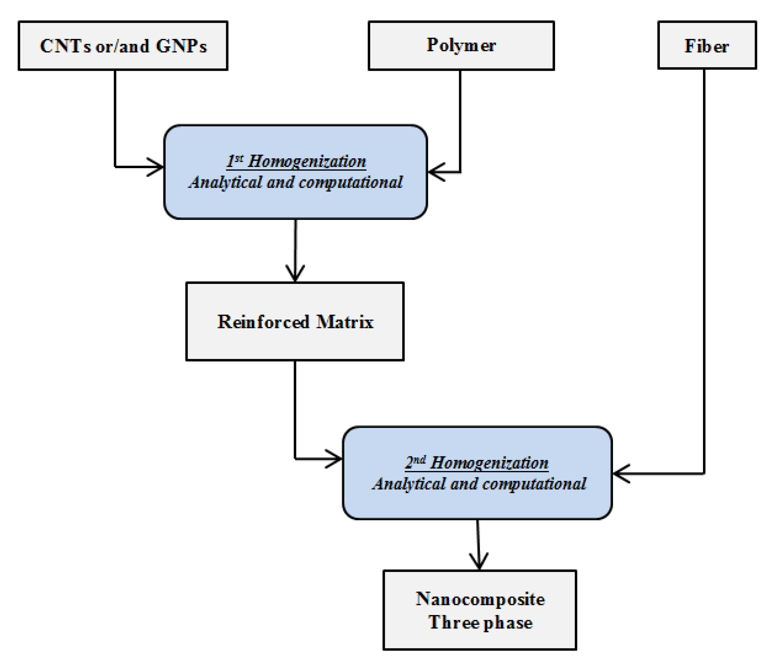
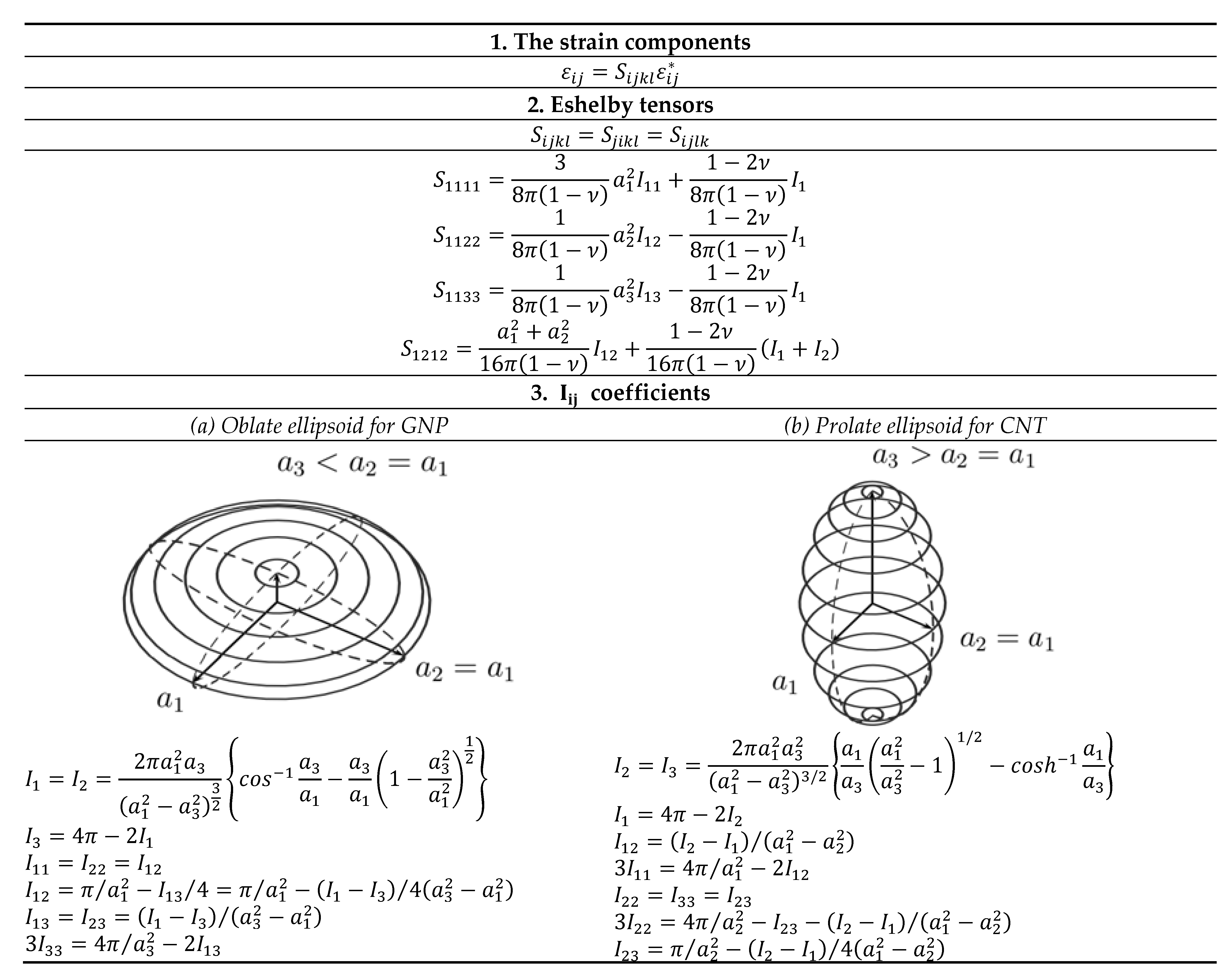
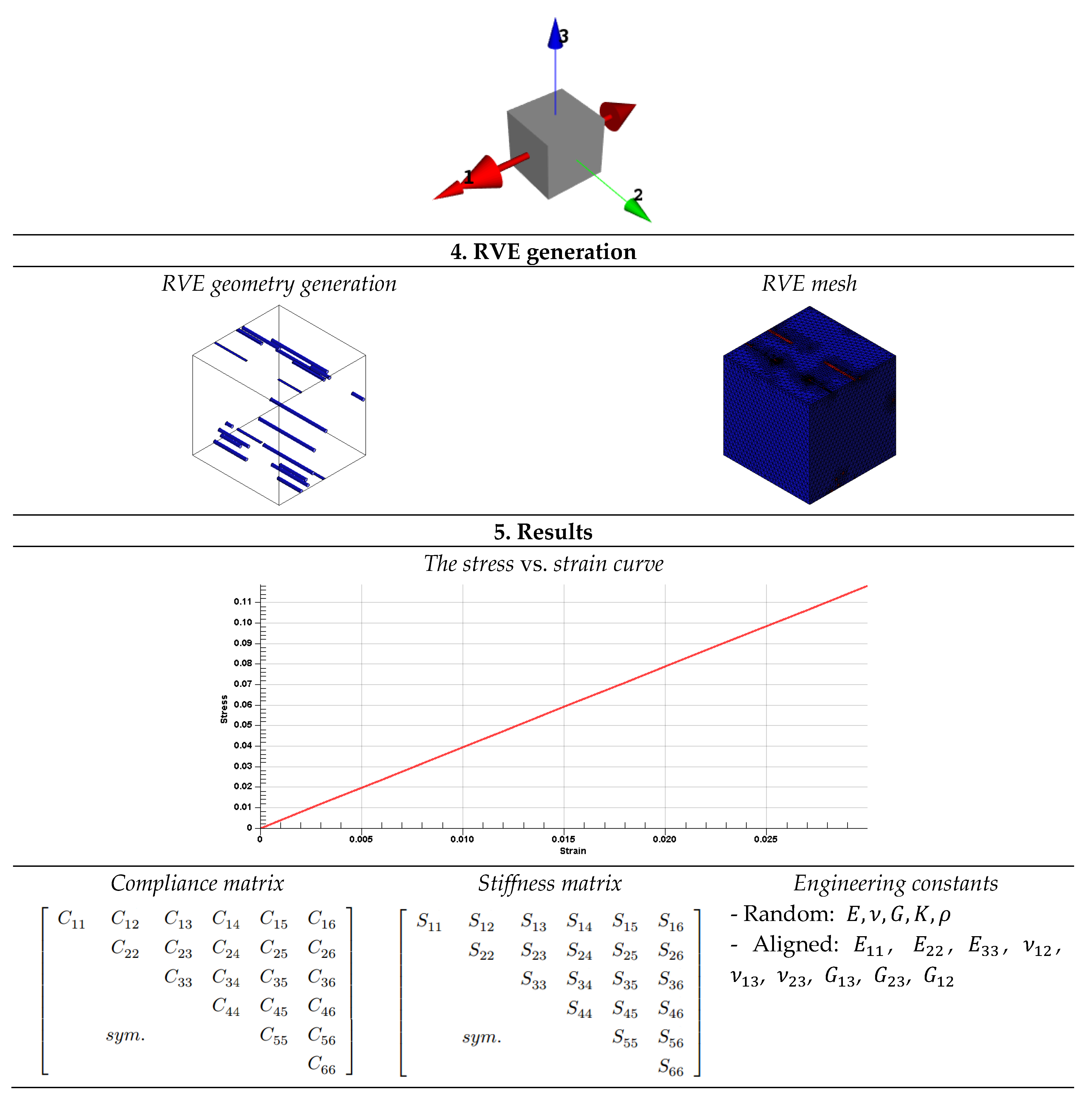
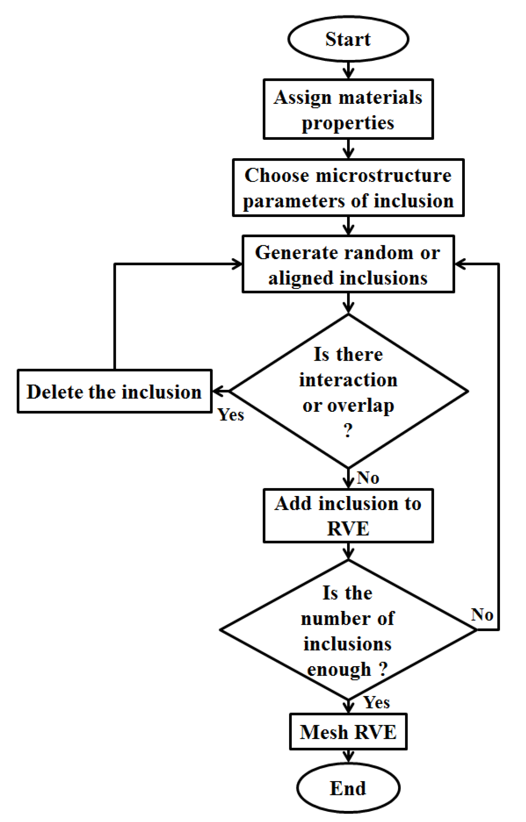
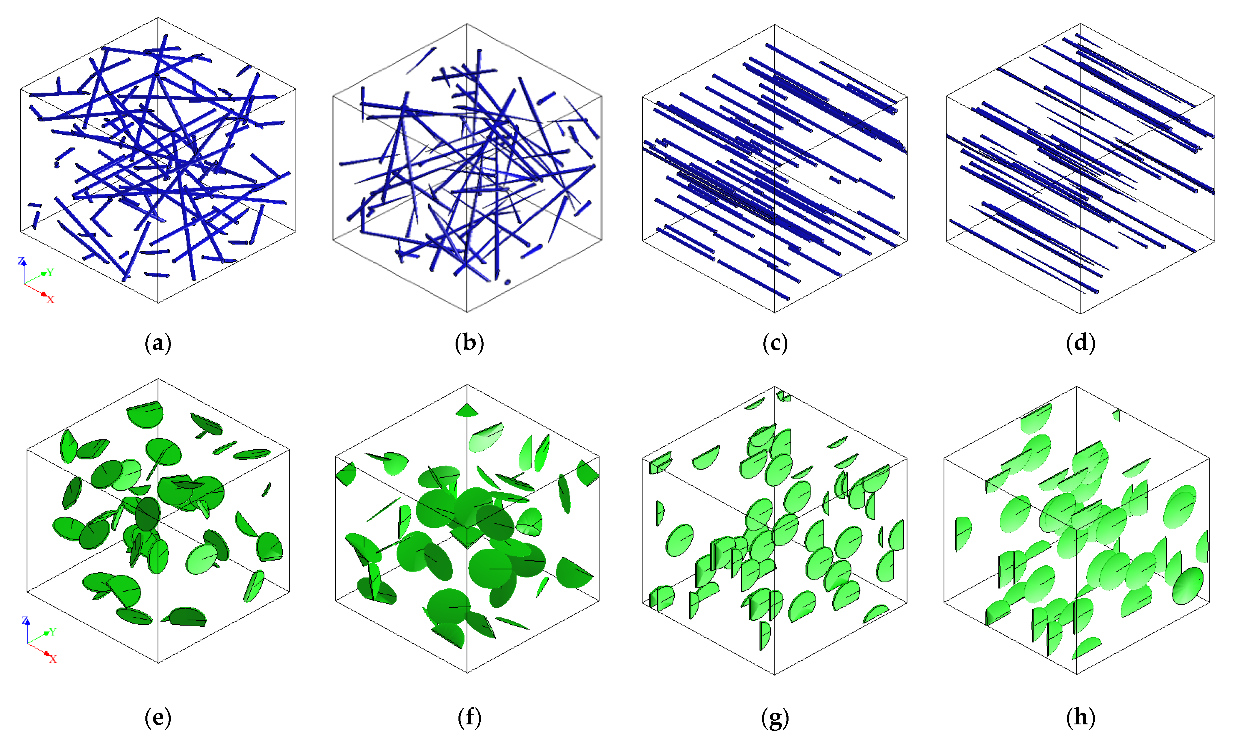
2. First Homogenization

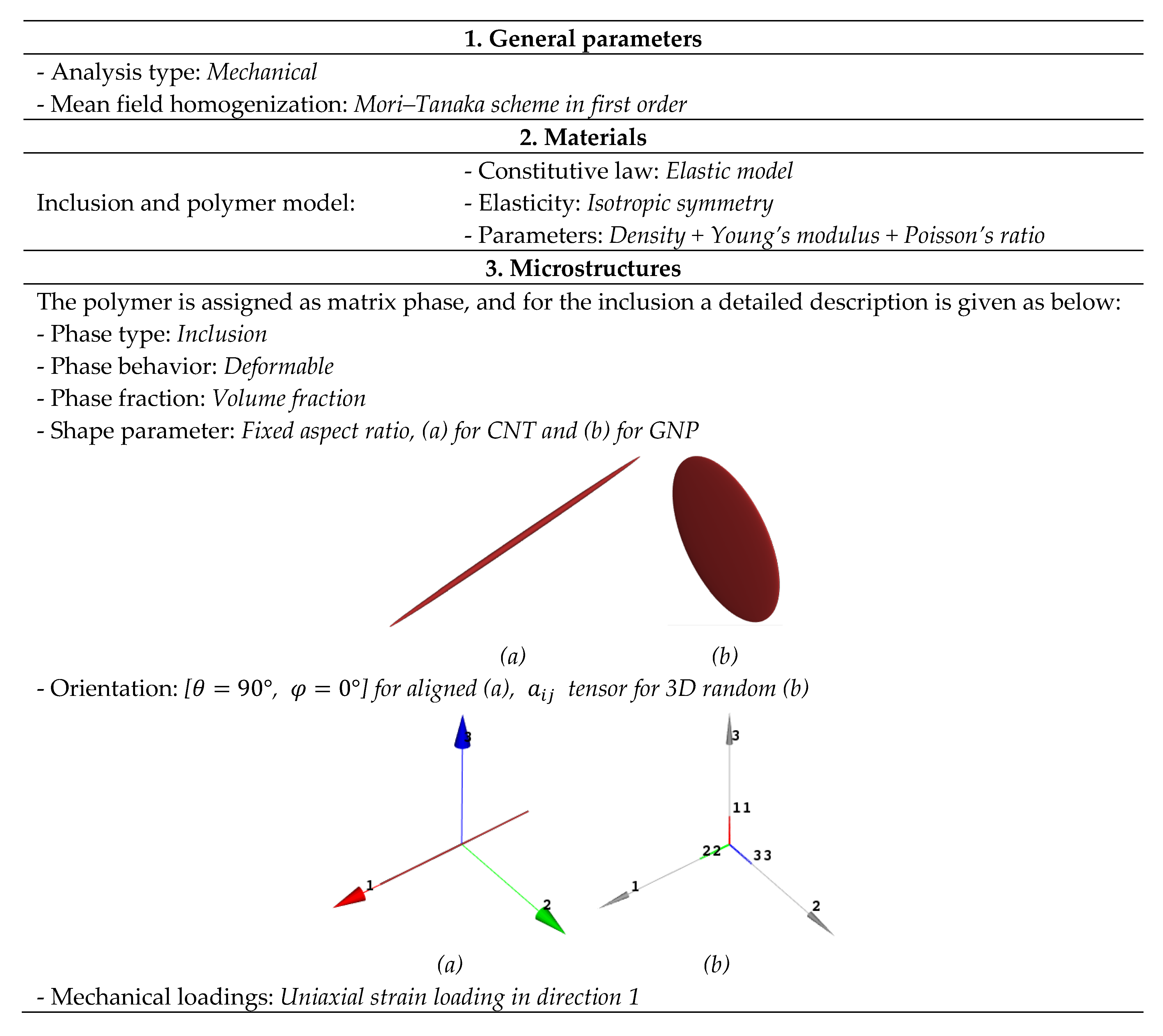
2.1. Mori–Tanaka Approach

The Mori–Tanaka approach [65,66,67,68] was used for the homogenization procedure, which is based on Eshelby tensor theory, in order to evaluate the effective transversely isotropic properties of CNT/GNP-reinforced matrix and fiber composite. The strain concentration factor A r d i l , which depends on the shape of the inclusion, is formulated for the rth inclusion as:
A r d i l = [ I + S r   C 0 1 ( C r C 0 ) ] 1
where S r is the Eshelby tensor for the rth inclusion, C 0 and C r are stiffness tensors for the matrix and rth inclusion, respectively. I represents the fourth order unity tensor [68].
The stiffness of the reinforced matrix for aligned inclusions can be defined as:
C C ,   a l i g n e d = ( V 0 C 0 + r = 1 N 1 V r C r A r d i l ) ( V 0 I + r = 1 N 1 V r A r d i l ) 1
where phase 0 is for matrix, and N 1 is for the remaining inclusion phases.
For randomly oriented inclusions, the average orientation is considered as indicated in curly brackets. Then, the effective stiffness of the reinforced matrix is written as:
C C ,   r a n d o m = ( V 0 C 0 + r = 1 N 1 V r {   C r A r d i l } ) ( V 0 I + r = 1 N 1 V r {   A r d i l } ) 1
The Eshelby tensor coefficients of the fourth order are dependent on the inclusion geometry. Similarly, the general Hooke’s law [69] is expressed as:
( σ 11 σ 22 σ 33 σ 12 σ 23 σ 31 ) = ( E 1111 E 1122 E 1133 0 0 0 E 1122 E 2222 E 2233 0 0 0 E 1133 E 2233 E 3333 0 0 0 0 0 0 E 1212 0 0 0 0 0 0 E 2323 0 0 0 0 0 0 E 3131 ) ( ε 11 ε 22 ε 33 γ 12 γ 23 γ 31 )
where ε i j is the strain tensor, σ i j is the stress tensor and γ i j is the shear strain tensor.
The five transversely isotropic constants of composite can be predicted through the Mori–Tanaka approach as:
E 11 = 1 S 1111     ν 12 = ν 13 = E 11 S 2211     G 12 = G 13 = 1 S 3131 E 22 = E 33 = 1 S 2222 ν 23 = E 22 S 3322 G 23 = 1 S 1212
where E 11 is the axial Young’s modulus, E 22 is the in-plane Young’s modulus, ν 12 is the transverse Poisson’s ratio, ν 23 is the in-plane Poisson’s ratio, G 12 is the transverse shear modulus and G 23 is the in-plane shear modulus. The Eshelby tensor S i j k l depends on the shape of inclusion [70], and their determination is summarized in the flowchart [71] either for the oblate or prolate form as shown in Figure 2.
The ratio between the length of the third axis a 3 and the first or second axis a 1 = a 2 is called the aspect ratio of the ellipsoid and denoted as α :
α = a 3 a 1 = a 2 a 1
Thus, CNT inclusion is considered as fiber-like spheroidal inclusions and their Eshelby tensor can be described as in Equation (7). For GNP inclusion, it considered as disc-shaped spheroidal inclusions, and their Eshelby tensor is given by the same equations in (7), but with g replaced by g described in Equation (9).
S 1111 = 1 2 ( 1 ν 0 ) { 1 2 ν 0 + 3 α 2 1 α 2 1 [ 1 2 ν 0 + 3 α 2 α 2 1 ] g } S 2222 = S 3333 = 3 8 ( 1 ν 0 ) α 2 α 2 1 + 1 4 ( 1 ν 0 ) [ 1 2 ν 0 + 9 4 ( α 2 1 ) ] g S 2233 = S 3322 = 1 4 ( 1 ν 0 ) { α 2 2 ( α 2 1 ) [ 1 2 ν 0 + 3 4 ( α 2 1 ) ] g } S 2211 = S 3311 = 1 2 ( 1 ν 0 ) α 2 α 2 1 + 1 4 ( 1 ν 0 ) { 3 α 2 α 2 1 ( 1 2 ν 0 ) } g S 1122 = S 1133 = 1 2 ( 1 ν 0 ) [ 1 2 ν 0 + 1 α 2 1 ] + 1 2 ( 1 ν 0 ) [ 1 2 ν 0 + 3 2 ( α 2 1 ) ] g S 2323 = S 3232 = 1 4 ( 1 ν 0 ) { α 2 2 ( α 2 1 ) + [ 1 2 ν 0 3 4 ( α 2 1 ) ] g } S 1212 = S 1313 = 1 4 ( 1 ν 0 ) { 1 2 ν 0 α 2 + 1 α 2 1 1 2 [ 1 2 ν 0 3 ( α 2 + 1 ) 4 ( α 2 1 ) ] g }
where
g = α ( α 2 1 ) 3 / 2 { α ( α 2 1 ) 1 / 2 c o s h 1 α }
where ν 0 is the matrix Poisson ratio.
g = α ( α 2 1 ) 3 / 2 { c o s 1 α α ( α 2 1 ) 1 / 2 }
In this work, a computational simulation of aligned and random CNT- and GNP-reinforced polymer has been processed to predict the effective elastic properties of the nanocomposite. Mori–Tanaka homogenization has been applied with finite element analysis by Digimat-FE. The details of FE analysis, including type of element, mesh generation and boundary conditions using the software Digimat-MF/FE [72], are described in Figure 3.
The representative volume elementary RVE model of CNT/GNP-reinforced polymer is generated by automatic random algorithm seed as shown in Figure 4. For CNT inclusion, it is considered to have two shapes: cylindrical and ellipsoidal (prolate) with aligned and random orientations, as seen in Figure 5a–d. For GNP inclusion, it is considered as platelets and ellipsoids (oblate) with aligned and random orientations, as shown in Figure 5e–h. There are many physical parameters of CNTs and GNPs influencing the elastic properties of nanocomposite, such as aspect ratio, volume fraction, orientation, agglomeration, interphase, etc. In the present work, just three parameters are investigated: the orientation, volume fraction and aspect ratio of nanofillers. The aspect ratios are AR = 50 and AR = 0.05 for CNT and GNP nanofillers, respectively. Therefore, the various phases used for our composites are: unsaturated polyester (UP) and polypropylene (PP) polymers, alfa and E-glass fibers and CNT and GNP nanofillers. The influence of elastic properties of the three phases is compared in the coming sections. The nanofillers, polymers and fibers have isotropic elastic properties as shown in Table 1.

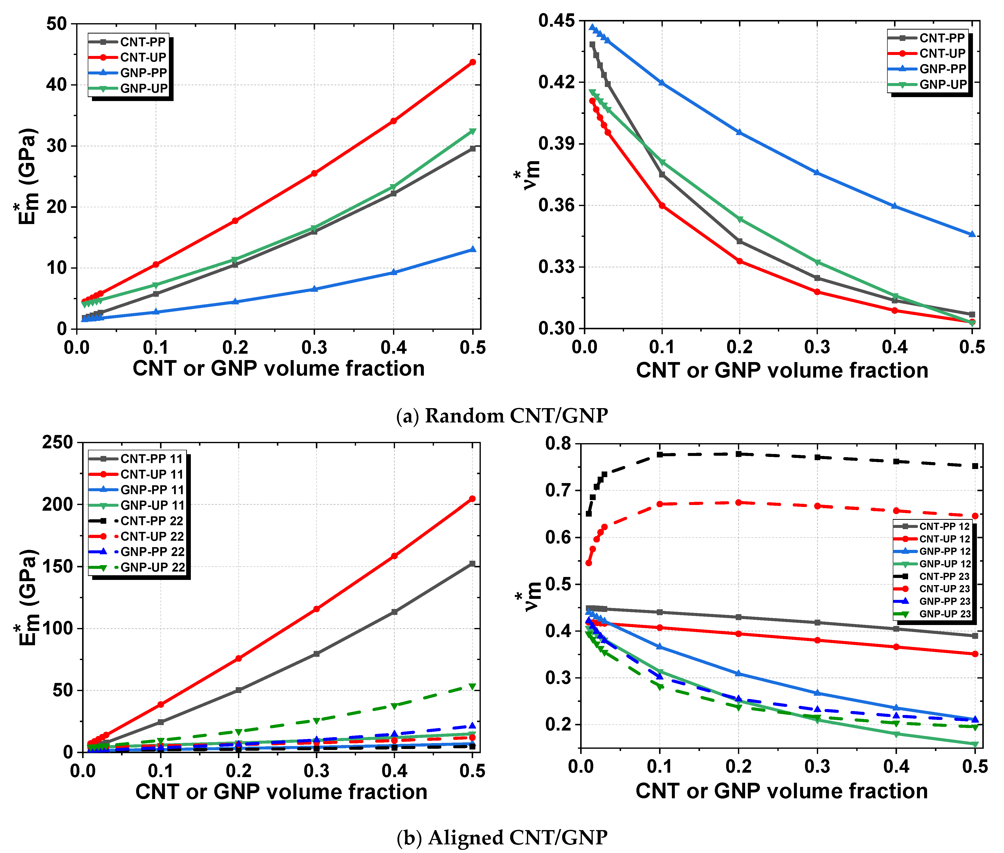
2.2. Results and Discussion

To guarantee the validity of our computational model, a comparison with analytical approaches has been considered, in the low- and high-volume fractions of inclusions. For the case of random CNT and GNP inclusions, the composite has an isotropic property. The effective Young’s modulus E m * and Poisson’s ratio ν m * are obtained by using the analytical approach of Mori–Tanaka with two other computational methods of Digimat-FE and Digimat-MF, where (*) indicates the effective mechanical properties of CNT- and GNP-reinforced matrix. The effect of volume fraction V f on elastic properties of composite has been investigated, with an aspect ratio of 50 for CNT and 0.05 for GNP as presented in Figure 6. The maximum volume fraction of the nanofillers is up to 50%. The Young’s modulus E m * and Poisson’s ratio ν m * are 500 GPa, 0.26 for CNTs and 1030 GPa, 0.19 for GNPs, and 1.4 GPa, 0.45 for PP (see Table 1). For a random CNT reinforcement of PP, Mori–Tanaka has E m * = 37.75 GPa and ν m * = 0.296, Digimat-MF has E m * = 29.56 GPa and ν m * = 0.306 as shown in Figure 6a; for random GNP reinforcement of PP, Mori–Tanaka has E m * = 13.0926 GPa and ν m * = 0.3457, Digimat-MF has E m * = 13.011 GPa and ν m * = 0.3452 (Figure 6b). There is a good agreement between analytical and computational elastic properties of random CNT-PP until 10% for E m * and ν m * as seen in Figure 6a. The elastic properties predicted by the FE method are similar to analytical results in a small volume fraction (<3%), where E m * has an error of 12.31% for CNT-PP and 2.8% for GNP-PP (Table 2), and ν m * has an error of 22.49% for CNT-PP and 5.78% for GNP-PP (Table 3). FE analysis gives accurate results and a detailed overview of the FE with complex inclusion morphology and offers the possibility to analyze the local stresses of the meso-structure, while MF only approximates engineering constants with less computing and CPU time. Thus, Digimat-FE considers that the composite has an orthotropic mechanical behavior, contrary to analytical models which consider that nanofillers have an isotropic behavior. In addition, in FE the inclusions are considered as cylindrical, but for MF the inclusions are considered as ellipsoidal.
In the case of aligned nanofillers, the composite has a transversely isotropic property. CNT-PP with a fiber shape has better elastic properties of composite in the longitudinal direction than in transverse direction. On the contrary, GNP-PP has better mechanical properties in the transverse direction than in the longitudinal direction because of its disc shape. As seen in Figure 6, Mori–Tanaka and Digimat-MF are agreed for all volume fractions, with longitudinal and transversal Young’s modulus and Poisson’s ratios of E 11 * ,  ν 23 * and E 22 * , ν 12 * , respectively.
In general, by increasing the CNT or GNP volume fraction, Young’s modulus E m * increases and Poisson’s ratio ν m * decreases, as demonstrated in Figure 7. The highest stiffness E m * is obtained for CNT-reinforced UP polymer and the lowest stiffness E m * is for GNP-reinforced PP. The comparison of Young’s modulus E m * and Poisson’s ratio ν m * of nanocomposites in transversal and longitudinal directions indicates that CNT-reinforced PP and UP in the longitudinal direction 11 have a higher Young’s modulus. The elastic properties deteriorate when the inclusion is random in comparison when the inclusions are aligned.
To conclude, in longitudinal direction 11, CNT-reinforced UP has enhanced elastic properties, and for transversal direction 22, GNP-reinforced UP has higher mechanical properties, which is explained by the molecular structure of CNTs and GNPs (Figure 8). Additionally, Young’s modulus E m * and Poisson’s ratio ν m * of CNT and GNP inclusions are better than those of UP and PP polymers.

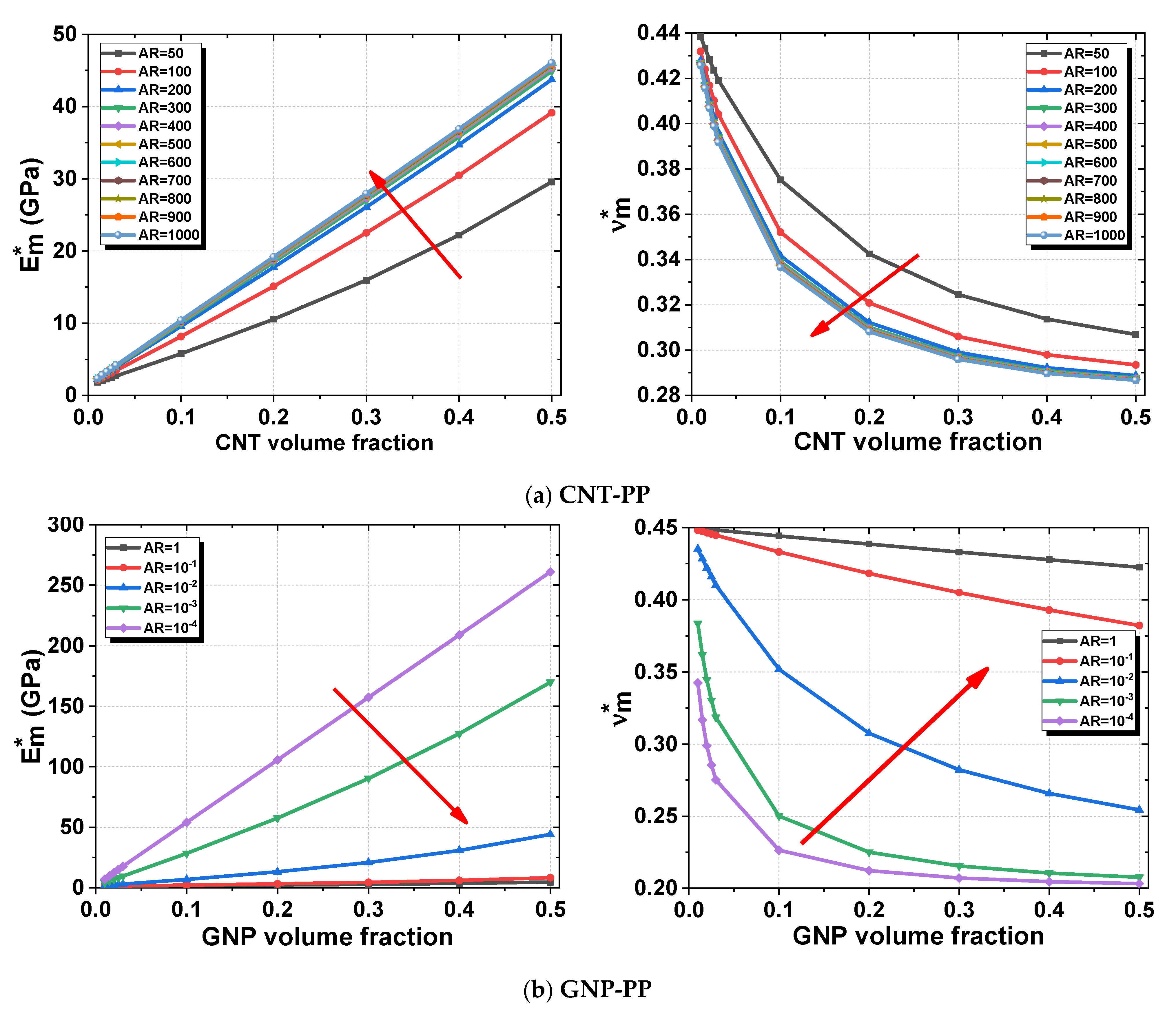
2.3. Effect of Aspect Ratio (AR)

The effect of the aspect ratio of CNT and GNP inclusions is considered to study the inclusions’ geometry effect on the elastic properties of reinforced PP and UP polymers of the first homogenization. This study is evaluated by Digimat-MF for the first homogenization, and CNTs and GNPs are assumed to be randomly oriented with an aspect ratio of 50–103 [79,80] for CNT inclusion and 1–10−4 [81] for GNP inclusion.
The effective Young’s modulus E m * and Poisson ratio ν m * have been computed using Digimat-MF for different aspect ratios as a function of the volume fraction of randomly CNT- and GNP-reinforced PP. The aspect ratio used for CNTs is in the range 50–103 with a step of 100, and 1–10−4 for GNPs with a step of 10−1. For CNT-PP, by increasing the volume fraction and aspect ratio, E m * increases nearly linearly with a maximum value of 50 GPa, and ν m * decreases with a minimum value of 0.29 (Figure 9a). For GNP-PP, E m * increases by increasing the volume fraction and decreases by increasing the aspect ratio, with a maximum value of 261 GPa for 10−4 (Figure 9b). It can be concluded that by increasing the aspect ratio of CNT inclusion, the elastic properties are enhanced considerably. This is contrary to GNP inclusion, which has degraded elastic properties by increasing the aspect ratio. This is due to the cylindrical form of CNTs and the platelet form of GNPs.

3. Second Homogenization

3.1. Mathematical Model

The matrix reinforced with random CNT and GNP inclusions obtained in the 1st homogenization was used with alfa and E-glass fibers in the 2nd homogenization. Analytical and computational methods have been used to investigate the mechanical properties of a composite. The results of E m * and ν m * obtained by the analytical Mori–Tanaka approach were used for the Chamis, Hashin–Rosen and Halpin–Tsai approaches described later. The results of E m * and ν m * obtained in the 1st homogenization by Digimat-MF were used in the 2nd homogenization by the same computational method (Digimat-MF/FE). An FE geometry of fiber-reinforced effective polymer has been modeled by Digimat-FE (Figure 10), the fiber used is continuous in the longitudinal direction 11 with a constant volume fraction of 50% and is perfectly bonded with the effective polymer. The computational and analytical elastic properties of the composite were compared. The effective volume fraction is closed to the reference volume fraction generated in RVE geometry, as seen in Table 4, which ensured the viability of the computational method. Composite geometry was meshed with 23,987 tetrahedron elements for the fiber and 30,128 for the matrix.

3.1.1. Chamis Approach

The method of Chamis [61,82] represents the most used homogenization technique, with five independent constants to describe the mechanical behavior of a composite. The equations defining the elastic properties of a unidirectional lamina made of anisotropic fibers in an isotropic matrix are formulated by Equations (10)–(15). Alfa and E-glass fibers are considered as isotropic; the axial and in-plane Young’s and shear modulus are the same, ( E 11 f = E 22 f ) and ( G 12 f = G 23 f ).
E 11 = E 11 f V f + E m * V m *
E 22 = E 33 = E m * 1 V f   ( 1 E m * / E 22 f )
G 12 = G 13 = G m * 1 V f   ( 1 G m * / G 12 f )
G 23 = G m * 1 V f   ( 1 G m * / G 23 f )
ν 12 = ν 13 = ν 12 f V f + ν m * V m *
ν 23 = E 22 2 G 23 1

3.1.2. Hashin–Rosen Approach

The Hashin–Rosen [62] homogenization approach is a variational method, it represents a simple technique to compute the mechanical behavior of unidirectional fiber-reinforced effective polymer in which both alfa and E-glass fibers and the matrix have isotropic characteristics. The final reinforced composite has transversely isotropic properties as expressed in Equations (16)–(30).
E 11 = E f V f + E m * V m * + 4 V f V m *   ( ν f ν m * ) 2   V m * / k ¯ f + V f / k ¯ m * + 1 / G m *
E 22 = E 33 = 4   k ¯ t G t k ¯ t + G t   ( 1 + 4 k ¯ t ( ν 12 ) 2 / E 11 )
ν 12 = ν 13 = ν f V f + ν m * V m * + V f V m * ( ν f ν m * ) ( 1 / k ¯ m * + 1 / k ¯ f ) V m * / k ¯ f + V f / k ¯ m * + 1 / G m *
G 12 = G 13 = G m * V m * G m * + ( 1 + V f ) G f ( 1 V f ) G m * + V m * G f
ν 23 = E 22 2 G t 1
G 23 = E 22 2 ( 1 + ν 23 )
where the parameters can be formulated as follows:
k ¯ f = E f 2 ( 1 ν f ( ν f ) 2
k ¯ m * = E m * 2 ( 1 ν m * (   ν m * ) 2
k ¯ t = k ¯ m * k ¯ f + ( V f k ¯ f + V m * k ¯ m * ) G m * V m * k ¯ f + V f k ¯ m * + G m *
G t = G m * ( α + β m * V f )   ( 1 + ξ ( V f ) 3 ) 3 V f ( V m * β m * ) 2 ( α V f ) ( 1 + ξ ( V f ) 3 ) 3 V f ( V m * β m * ) 2
α = G t / G m * + β m * G t / G m * 1
β m * = 1 3 4 ν m *
β f = 1 3 ν f
G f = E f 2 ( 1 + ν f )
ξ = β m * β f G f / G m * 1 + β f G f / G m *
where E f , ν f , V f and G f are Young’s modulus, Poisson’s ratio, volume fraction and shear modulus of fiber, respectively. E m * , ν m * , V m * and G m * are Young’s modulus, Poisson’s ratio, volume fraction and shear modulus of the effective matrix, respectively. k ¯ f and k ¯ m * denote the plane strain bulk moduli for the fibers and effective matrix, respectively.

3.1.3. Halpin–Tsai Approach

The Halpin–Tsai model [83] is used to predict the mechanical properties of composites reinforced by short fibers. However, these equations were primarily developed for long-fiber composites [84]. The elastic properties can be formulated as:
P P m = 1 + ζ η V f 1 η V f
η = P f / P m 1 P f / P m + ζ
where P represents the property of the composite of which P f and P m are the corresponding fibers and effective matrix properties, respectively, including Young’s modulus E , Poisson’s ratio ν and shear modulus G . V f is the volume fraction of fiber and ζ is the geometry parameter of fiber calculated as follows:
  • ζ = 2 l / d for calculation of the longitudinal modulus.
  • ζ = 2 for calculation of the transversal modulus.

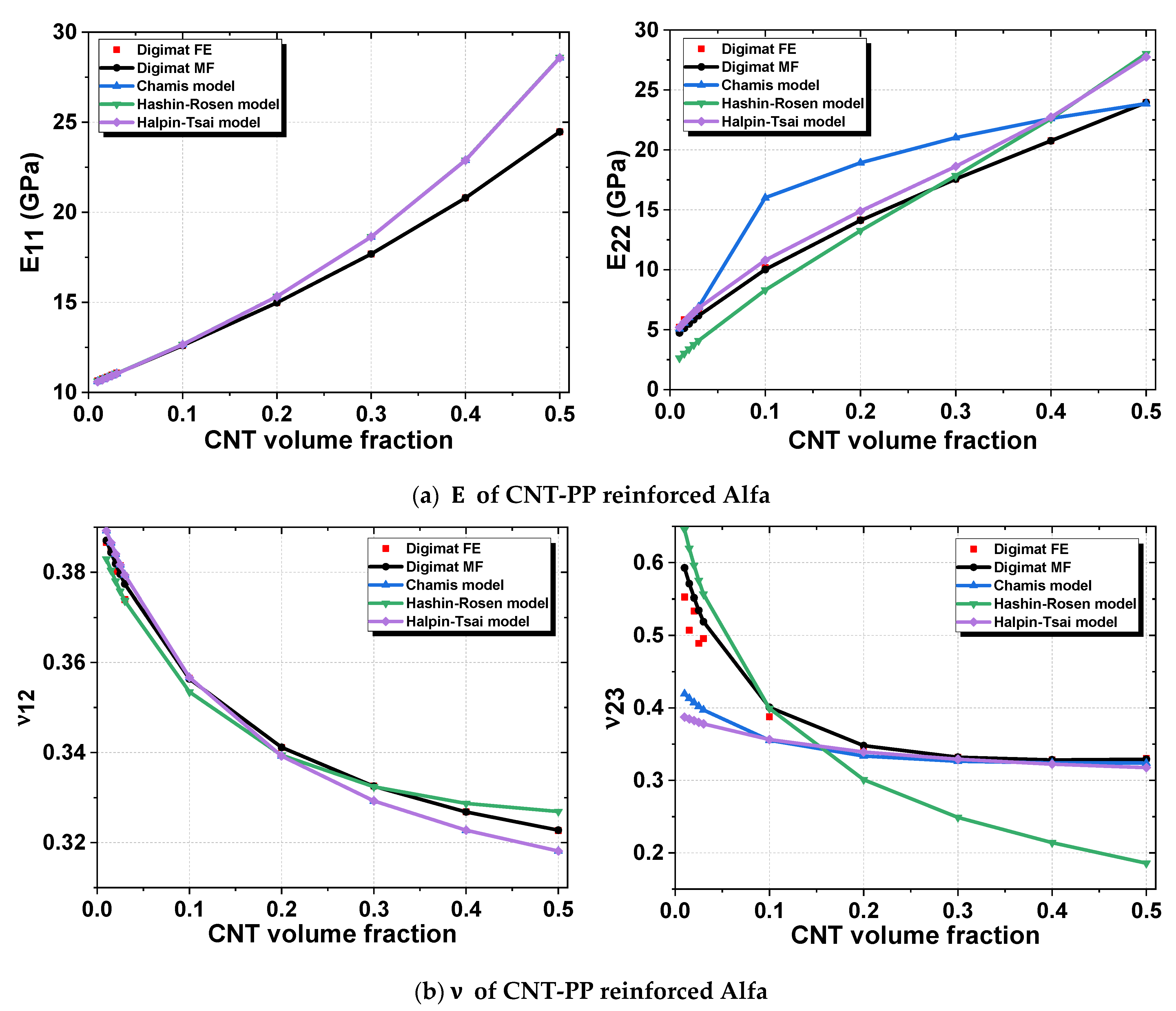
3.2. Results and Discussion

Figure 11a clearly shows that longitudinal Young’s modulus E 11 of aligned alfa fiber-reinforced CNT-PP polymer increases by varying the nanofiller volume fraction. The effective Young’s modulus E 11 of fiber-reinforced polymer obtained from Digimat-MF/FE, Chamis, Halpin–Tsai and Hashin–Rosen methods shows good predictions for low volume fractions of nanofillers. Note that results in the computational method with Digimat-MF and FE are matched. E 11 has a maximum value of 28.57 GPa for analytical methods and 24.46 GPa for computational methods. The values of transversal Young’s modulus E 22 obtained from analytical and computational methods shows a non-linear relationship with a maximum value of 24 GPa for computational methods and 27 GPa for analytical methods. The value of Young’s modulus E 22 increases as the CNT volume fraction increases. Analytical results are quite far from computational results, especially for high-volume fractions. The Hashin–Rosen, Halpin–Tsai and Chamis methods overestimated FE results. In Figure 11b, the transverse Poisson’s ratio ν 12 decreases linearly by increasing the CNT volume fraction. Computational results closely match the values of all analytical methods until 20%. Then ν 12 of Hashin–Rosen is above Digimat-MF/FE from 30% with a value of 0.326, and Chamis and Halpin–Tsai are below Digimat-MF/FE with a value of 0.318. The in-plane Poisson’s ratio ν 23 decreases as a function of the CNT volume fraction. It is observed that the graph is non-linear, and ν 23 decreases till it reaches its minimum value of 0.331 for Chamis and Halpin–Tsai in which the CNT volume fraction does not show any considerable influence on ν 23 from 20%, and they are close with a difference of 8.1%. Hashin–Rosen and Digimat-MF/FE are close until 10%. ν 23 decreases sharply and approaches zero for Hashin–Rosen. It is concluded that the mechanical properties of the composite are stronger in the longitudinal direction of the fibers than in the transverse direction. For Young’s modulus, computational results of E 11 are greater than E 22 by 2.03%. For Poisson’s ratio, ν 23 is higher than ν 12 by 2.12%.
For alfa-reinforced GNP-PP, analytical and computational results of axial Young’s modulus E 11 are in good agreement with a value of 16.2 GPa, and for transversal Young’s modulus E 22 = 15.88 GPa, where Chamis and Hashin–Rosen overestimate the FE results (Figure 12a). The transverse Poisson’s ratio ν 12 decreases as a function of volume fraction (Figure 12b) where all results converge to 0.342. For 1%, ν 12 has a value of 0.3904, 0.3912, 0.3933, 0.3870 and 0.3910 for Digimat-FE, MF, Chamis, Hashin–Rosen and Halpin–Tsai, respectively. The in-plane Poisson’s ratio ν 23 of Digimat-FE, MF and Hashin–Rosen models decreases and Halpin–Tsai remains quite constant, while Chamis increases until a maximum of 0.6 at 20% and then decreases. All analytical models overestimate the computational results, in which ν 23 has a minimum value of 0.3459, 0.3461, 0.5260, 0.3925 and 0.3425 for Digimat-FE, MF, Chamis, Hashin–Rosen and Halpin–Tsai, respectively.
It is concluded that the numerical results of CNT/GNP-PP-reinforced alfa are much more accurate than the analytical results, and the inclusion of CNT reinforces the alfa fiber much more than GNPs, although GNPs have a higher Young’s modulus. It is observed that the prolate form of CNTs is stronger than the oblate form of GNPs. The value of E 11 of CNT composite is 33.36% higher than that of GNP composite, and for E 22 , it is also higher by 33.16%.
The longitudinal Young’s modulus E 11 increases as a function of CNT and GNP volume fraction-reinforced alfa and glass fibers with PP and UP polymers. Glass-reinforced matrix has an E 11 greater than alfa-reinforced matrix, especially for UP polymer (Figure 13a). Alfa fiber-reinforced polymer has maximum values of E 11 in the order of 31.58 GPa, 25.96 GPa, 24.47 GPa and 16.2 GPa for CNT-UP, GNP-UP, CNT-PP and GNP-PP, respectively. Concerning glass fiber-reinforced polymer, E 11 has maximum values in the order of 58.43 GPa, 52.8 GPa, 51.33 GPa and 43.06 GPa for CNT-UP, GNP-UP, CNT-PP and GNP-PP, respectively. Good mechanical properties have been observed for CNT-UP effective matrix and the worst for GNP-PP. In addition, the transversal Young’s modulus E 22 is lower than E 11 (Figure 13b). Alfa-reinforced composite has a higher transverse Poisson’s ratio ν 12 than glass-reinforced composite (Figure 13c). The in-plane Poisson’s ratio ν 23 of glass-reinforced composite decreases for all volume fractions, while that of alfa-reinforced composite decreases until 30% and then remains constant for UP matrix (Figure 13d). It is concluded that CNT inclusion and glass fibers have a greater effect than GNP inclusion and alfa fibers on the mechanical performance of biocomposite. When the volume fraction of CNT and GNP inclusions is large, their mechanical properties dominate over those of alfa and glass fiber. Due to their high elastic properties, UP polymer, CNT inclusion and glass fiber can improve the composite property more than PP polymer, GNP inclusion and alfa fiber. GNPs have a higher Young’s modulus than CNTs, but because of their plate shape, the composite has not increased mechanical stiffness. Focusing on the alfa fiber, for polymer, E 11 of alfa CNT-UP has a higher value than alfa CNT-PP by 22.51%. For inclusion, alfa CNT-UP has an E 11 value greater than alfa GNP-UP by 17.01%. In the same way, E 11 of glass CNT-UP is 46.38% greater than alfa CNT-UP. The same observations were found for the other elastic properties of E 22 , v 12 and v 23 . It is observed that in the three phases of the biocomposite, CNT and GNP inclusions dominated the mechanical properties at high volume fractions.

4. Conclusions

This study is a comparison between homogenization methods, and also between the performance of synthetic and natural materials used for the benefit of wind turbine blades. The elastic performance of alfa and E-glass composites with CNT and GNP inclusion-reinforced PP and UP polymers was investigated using computational and analytical approaches. The influence of volume fraction, aspect ratio and orientation on the mechanical properties of nanocomposites was highlighted. It is shown that the mechanical–elastic properties can be significantly affected by the shape of the inclusions and their orientation, in particular for large volume fractions and aspect ratios. The following important observations are highlighted:
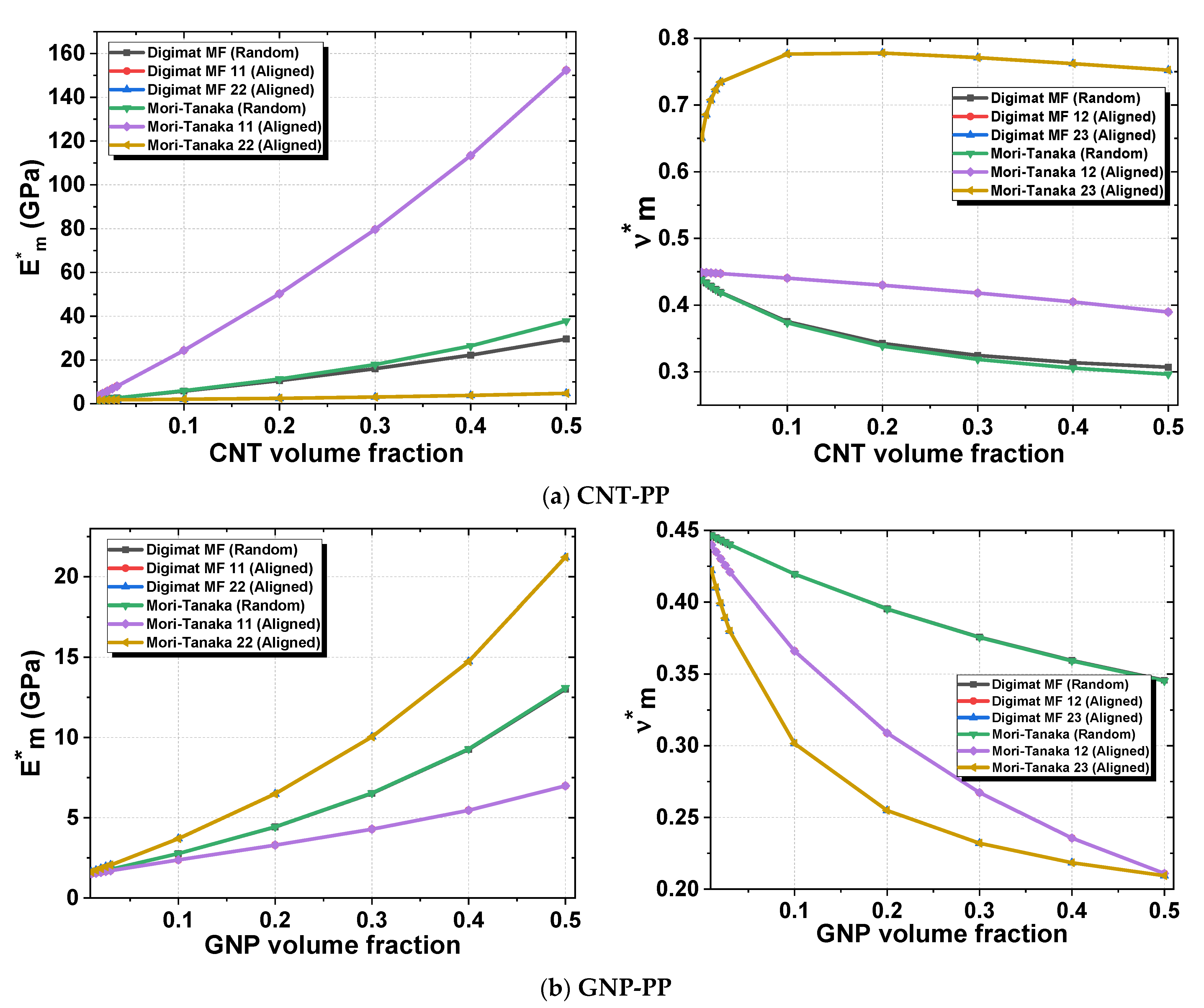
  • Computational and analytical models are in good agreement for aligned inclusions with enhanced mechanical properties for all volume fractions, contrary to random inclusions which are in good agreement until 10% of volume fraction.
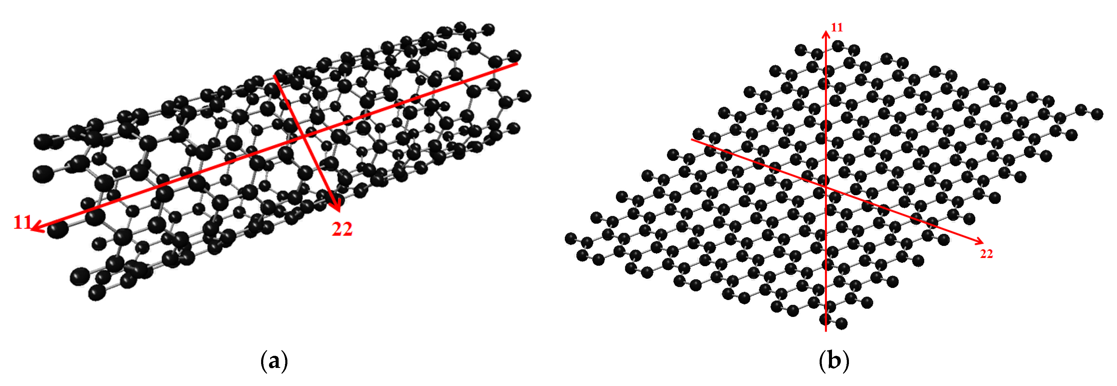
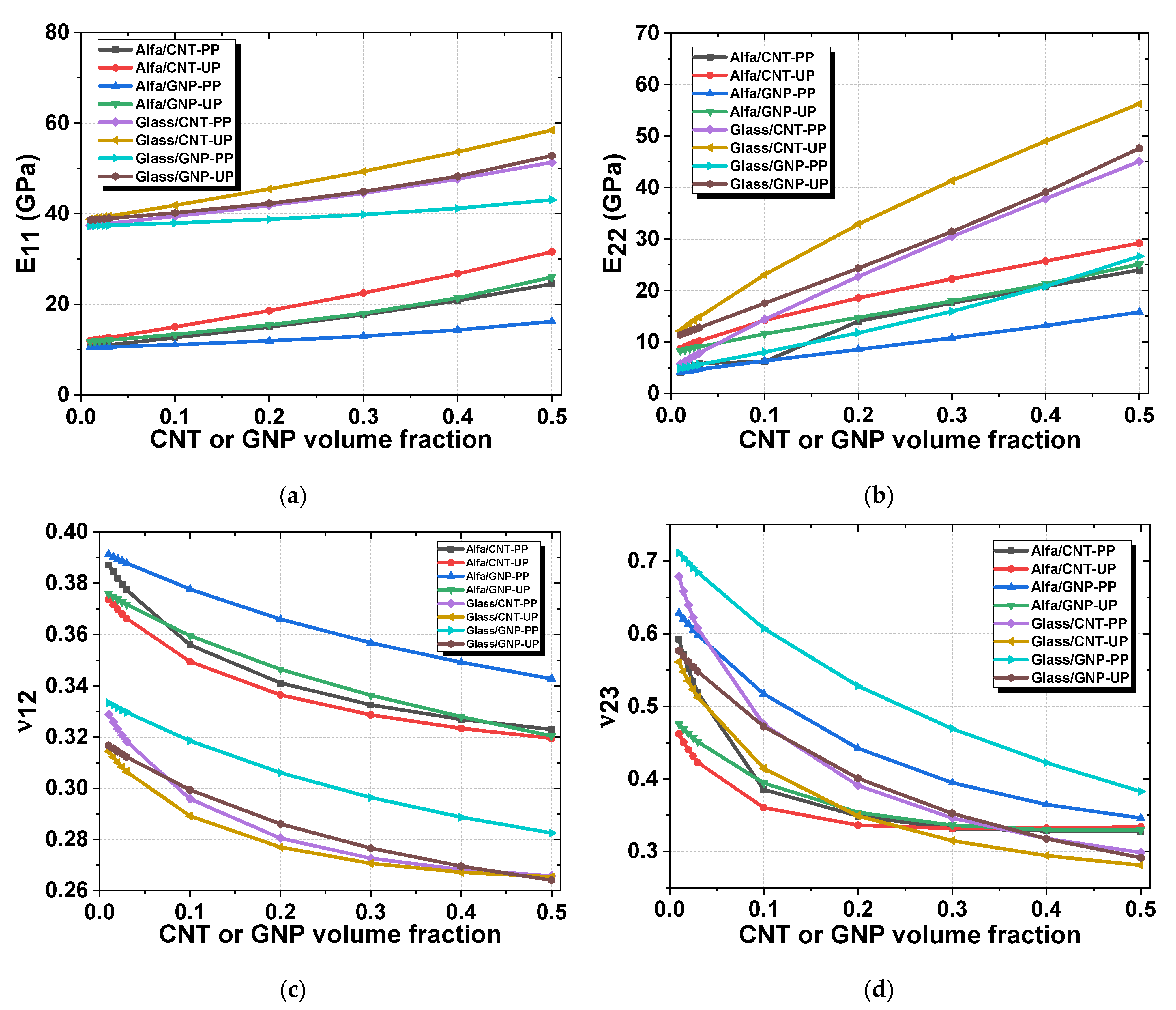
  • Due to its shape, the improved mechanical properties of the CNT matrix are in the longitudinal axis and for the GNP matrix are in the transversal axis. In addition, it is observed that CNT- and GNP-reinforced UP has enhanced mechanical properties in comparison with PP polymer for random and aligned inclusions. Additionally, the elastic properties of inclusions dominate those of polymers and fibers. The effect of aspect ratio (AR) on elastic properties has been studied, and by increasing AR from 50 to 103, E m * increases for CNTs and, by decreasing AR from 1 to 10−4, E m * increases for GNPs, which demonstrates that the shape of inclusions is significant
  • In the 1st homogenization of aligned CNT-reinforced PP, longitudinal Young’s modulus E 11 = 152.35 GPa is greater than the random E m * = 4.77 GPa, and transversal E 22 = 29.56 GPa is lower than E m * . Concerning GNP-reinforced PP, transversal E 22 = 21.21 GPa is greater than the random E m * = 13.01 GPa and E 11 = 6.98 GPa is lower than E m * . For random inclusions, CNT- and GNP-reinforced UP has improved Young’s modulus E m * , and for aligned inclusions, enhanced Young’s modulus is shown by CNT-UP in the axial direction (11) and GNP-UP in the transversal direction (22).
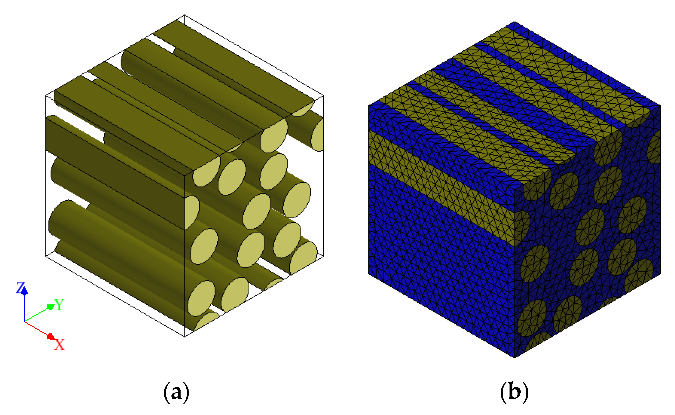
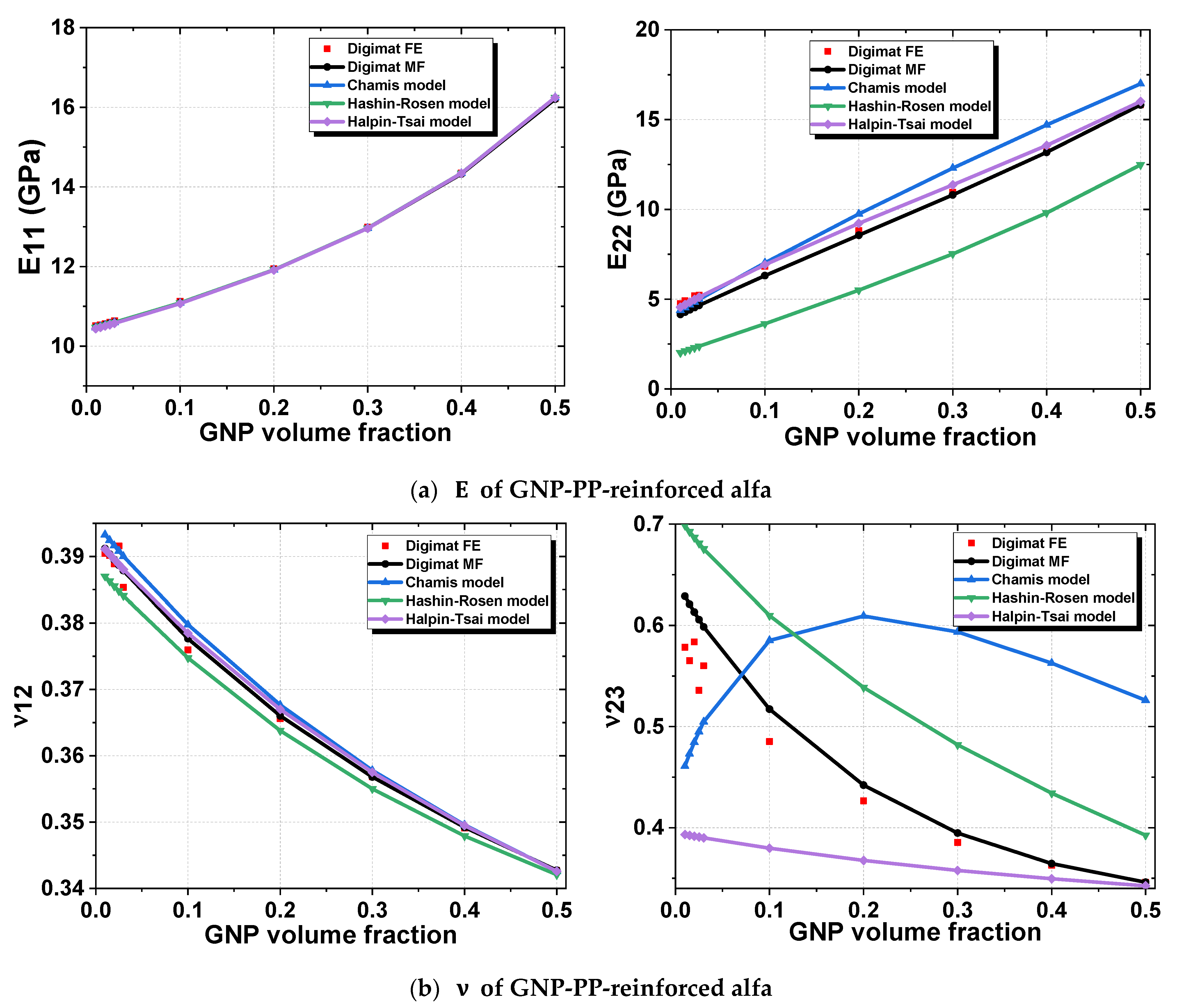
  • In the 2nd homogenization, CNT-PP-reinforced alfa composite has transversely isotropic properties, and has a longitudinal Young’s modulus E 11 = 24.46 GPa close to the transversal Young’s modulus E 22 = 23.97 GPa. The in-plane Poisson’s ratio ν 23 = 0.33 is close to the transverse ν 12 = 0.32. For GNP-PP-reinforced Alfa, E 11 = 16.22 GPa is greater than E 22 = 15.82 GPa and ν 23 = 0.35 is greater than ν 12 = 0.34. It is observed that the mechanical properties of the biocomposite are somewhat more favorable in the longitudinal direction than transversal because the volume fraction of the alfa fiber is 50%, and the rest is for the matrix reinforced by random CNTs and GNPs that dominate the mechanical behavior of the biocomposite.
  • The alfa fibers present a promising alternative to the synthetic fibers of E-glass used in wind turbine blade fabrication because of their lightness, availability and biodegradability.

Author Contributions

M.R. and M.N.: investigation, methodology, data curation, conceptualization, writing—original draft preparation, writing—reviewing and editing. M.T.: supervision, writing—reviewing and editing, validation. N.C., L.E.H.O., F.F. and O.C.: supervision, validation. All authors have read and agreed to the published version of the manuscript.

Funding

This research received no external funding.

Institutional Review Board Statement

Not applicable.

Informed Consent Statement

Not applicable.

Conflicts of Interest

The authors declare no conflict of interest.

References

  1. Tarfaoui, M.; Shah, O.R.; Nachtane, M. Design and Optimization of Composite Offshore Wind Turbine Blades. J. Energy Resour. Technol. 2019, 141. [Google Scholar] [CrossRef]
  2. Nachtane, M.; Tarfaoui, M.; El Moumen, A.; Saifaoui, D. Numerical Investigation of Damage Progressive in Composite Tidal Turbine for Renewable Marine Energy. In Proceedings of the 2016 International Renewable and Sustainable Energy Conference (IRSEC), Marrakech, Morocco, 14–17 November 2016; pp. 559–563. [Google Scholar]
  3. Nachtane, M.; Tarfaoui, M.; Goda, I.; Rouway, M. A Review on the Technologies, Design Considerations and Numerical Models of Tidal Current Turbines. Renew. Energy 2020, 157, 1274–1288. [Google Scholar] [CrossRef]
  4. Nachtane, M.; Tarfaoui, M.; Ait Mohammed, M.; Saifaoui, D.; El Moumen, A. Effects of Environmental Exposure on the Mechanical Properties of Composite Tidal Current Turbine. Renew. Energy 2020, 156, 1132–1145. [Google Scholar] [CrossRef]
  5. Belfkira, Z.; Mounir, H.; El Marjani, A. Structural Optimization of a Horizontal Axis Wind Turbine Blade Made from New Hybrid Composites with Kenaf Fibers. Compos. Struct. 2021, 260, 113252. [Google Scholar] [CrossRef]
  6. Boria, S.; Santulli, C.; Raponi, E.; Sarasini, F.; Tirillò, J. Evaluation of a New Green Composite Solution for Wind Turbine Blades. Multiscale Multidiscip. Model. Exp. Des. 2019, 2, 141–150. [Google Scholar] [CrossRef]
  7. Mekonnen, B.Y.; Mamo, Y.J. Tensile and Flexural Analysis of a Hybrid Bamboo/Jute Fiber-Reinforced Composite with Polyester Matrix as a Sustainable Green Material for Wind Turbine Blades. Int. J. Eng. 2020, 33, 314–319. [Google Scholar] [CrossRef]
  8. Shah, D.U.; Schubel, P.J.; Clifford, M.J. Can Flax Replace E-Glass in Structural Composites? A Small Wind Turbine Blade Case Study. Compos. Part. B Eng. 2013, 52, 172–181. [Google Scholar] [CrossRef] [Green Version]
  9. Huang, X.-D.; Hse, C.-Y.; Shupe, T.F. Evaluation of the Performance of the Composite Bamboo/Epoxy Laminated Material for Wind Turbine Blades Technology. BioResources 2015, 10, 660–671. [Google Scholar] [CrossRef]
  10. Kalagi, G.R.; Patil, R.; Nayak, N. Experimental Study on Mechanical Properties of Natural Fiber Reinforced Polymer Composite Materials for Wind Turbine Blades. Mater. Today Proc. 2018, 5, 2588–2596. [Google Scholar] [CrossRef]
  11. Tarfaoui, M.; El Moumen, A.; Ben Yahia, H. Damage Detection versus Heat Dissipation in E-Glass/Epoxy Laminated Composites under Dynamic Compression at High Strain Rate. Compos. Struct. 2018, 186, 50–61. [Google Scholar] [CrossRef] [Green Version]
  12. Tarfaoui, M.; El Moumen, A.; Lafdi, K. Progressive Damage Modeling in Carbon Fibers/Carbon Nanotubes Reinforced Polymer Composites. Compos. Part. B Eng. 2017, 112, 185–195. [Google Scholar] [CrossRef]
  13. Mishnaevsky, L.; Branner, K.; Petersen, H.N.; Beauson, J.; McGugan, M.; Sørensen, B.F. Materials for Wind Turbine Blades: An Overview. Materials 2017, 10, 1285. [Google Scholar] [CrossRef] [Green Version]
  14. Hamdan, A.; Mustapha, F.; Ahmad, K.A.; Mohd Rafie, A.S. A Review on the Micro Energy Harvester in Structural Health Monitoring (SHM) of Biocomposite Material for Vertical Axis Wind Turbine (VAWT) System: A Malaysia Perspective. Renew. Sustain. Energy Rev. 2014, 35, 23–30. [Google Scholar] [CrossRef]
  15. Rouway, M.; Nachtane, M.; Tarfaoui, M.; Chakhchaoui, N.; Omari, L.; Fraija, F.; Cherkaoui, O. Prediction of Mechanical Performance of Natural Fibers Polypropylene Composites: A Comparison Study. IOP Conf. Ser. Mater. Sci. Eng. 2020, 948, 012031. [Google Scholar] [CrossRef]
  16. Brown, K.A.; Brooks, R. Design and Analysis of Vertical Axis Thermoplastic Composite Wind Turbine Blade. Plast. Rubber Compos. 2010, 39, 111–121. [Google Scholar] [CrossRef]
  17. Geng, Y.; Liu, M.Y.; Li, J.; Shi, X.M.; Kim, J.K. Effects of Surfactant Treatment on Mechanical and Electrical Properties of CNT/Epoxy Nanocomposites. Compos. Part. Appl. Sci. Manuf. 2008, 39, 1876–1883. [Google Scholar] [CrossRef]
  18. El Moumen, A.; Tarfaoui, M.; Nachtane, M.; Lafdi, K. Carbon Nanotubes as a Player to Improve Mechanical Shock Wave Absorption. Compos. Part. B Eng. 2019, 164, 67–71. [Google Scholar] [CrossRef]
  19. Benyahia, H.; Tarfaoui, M.; Datsyuk, V.; El Moumen, A.; Trotsenko, S.; Reich, S. Dynamic Properties of Hybrid Composite Structures Based Multiwalled Carbon Nanotubes. Compos. Sci. Technol. 2017, 148, 70–79. [Google Scholar] [CrossRef]
  20. Tarfaoui, M.; Lafdi, K.; El Moumen, A. Mechanical Properties of Carbon Nanotubes Based Polymer Composites. Compos. Part. B Eng. 2016, 103, 113–121. [Google Scholar] [CrossRef]
  21. Nachtane, M.; Tarfaoui, M.; Ledoux, Y.; Khammassi, S.; Leneveu, E.; Pelleter, J. Experimental Investigation on the Dynamic Behavior of 3D Printed CF-PEKK Composite under Cyclic Uniaxial Compression. Compos. Struct. 2020, 247, 112474. [Google Scholar] [CrossRef]
  22. Naebe, M.; Abolhasani, M.M.; Khayyam, H.; Amini, A.; Fox, B. Crack Damage in Polymers and Composites: A Review. Polym. Rev. 2016, 56, 31–69. [Google Scholar] [CrossRef]
  23. An, Q.; Rider, A.N.; Thostenson, E.T. Electrophoretic Deposition of Carbon Nanotubes onto Carbon-Fiber Fabric for Production of Carbon/Epoxy Composites with Improved Mechanical Properties. Carbon 2012, 50, 4130–4143. [Google Scholar] [CrossRef]
  24. Davis, D.C.; Wilkerson, J.W.; Zhu, J.; Hadjiev, V.G. A Strategy for Improving Mechanical Properties of a Fiber Reinforced Epoxy Composite Using Functionalized Carbon Nanotubes. Compos. Sci. Technol. 2011, 71, 1089–1097. [Google Scholar] [CrossRef]
  25. Sassi, S.; Tarfaoui, M.; Yahia, H.B. Thermomechanical Behavior of Adhesively Bonded Joints under Out-of-Plane Dynamic Compression Loading at High Strain Rate. J. Compos. Mater. 2018, 52, 4171–4184. [Google Scholar] [CrossRef]
  26. Al Habis, N.; El Moumen, A.; Tarfaoui, M.; Lafdi, K. Mechanical Properties of Carbon Black/Poly (ε-Caprolactone)-Based Tissue Scaffolds. Arab. J. Chem. 2020, 13, 3210–3217. [Google Scholar] [CrossRef]
  27. Tarfaoui, M.; El Moumen, A.; Lafdi, K.; Hassoon, O.; Nachtane, M. Inter Laminar Failure Behavior in Laminate Carbon Nanotubes-Based Polymer Composites. J. Compos. Mater. 2018, 52, 3655–3667. [Google Scholar] [CrossRef]
  28. Tarfaoui, M.; Lafdi, K.; Beloufa, I.; Daloia, D.; Muhsan, A. Effect of Graphene Nano-Additives on the Local Mechanical Behavior of Derived Polymer Nanocomposites. Polymers 2018, 10, 667. [Google Scholar] [CrossRef] [Green Version]
  29. El Moumen, A.; Tarfaoui, M.; Lafdi, K. Computational Homogenization of Mechanical Properties for Laminate Composites Reinforced with Thin Film Made of Carbon Nanotubes. Appl. Compos. Mater. 2018, 25, 569–588. [Google Scholar] [CrossRef]
  30. Hassoon, O.H.; Tarfaoui, M.; El Moumen, A.; Qureshi, Y.; Benyahia, H.; Nachtane, M. Mechanical Performance Evaluation of Sandwich Panels Exposed to Slamming Impacts: Comparison between Experimental and SPH Results. Compos. Struct. 2019, 220, 776–783. [Google Scholar] [CrossRef]
  31. Tarfaoui, M.; El Moumen, A.; Boehle, M.; Shah, O.; Lafdi, K. Self-Heating and Deicing Epoxy/Glass Fiber Based Carbon Nanotubes Buckypaper Composite. J. Mater. Sci. 2019, 54, 1351–1362. [Google Scholar] [CrossRef]
  32. Shi, X.; Gholamalizadeh, E.; Moheimani, R. Applying a Micromechanics Approach for Predicting Thermal Conducting Properties of Carbon Nanotube-Metal Nanocomposites. J. Alloy. Compd. 2019, 789, 528–536. [Google Scholar] [CrossRef]
  33. Hassanzadeh-Aghdam, M.K.; Mahmoodi, M.J.; Jamali, J.; Ansari, R. A New Micromechanical Method for the Analysis of Thermal Conductivities of Unidirectional Fiber/CNT-Reinforced Polymer Hybrid Nanocomposites. Compos. Part. B Eng. 2019, 175, 107137. [Google Scholar] [CrossRef]
  34. Xiong, L.; Shuai, J.; Liu, K.; Hou, Z.; Zhu, L.; Li, W. Enhanced Mechanical and Electrical Properties of Super-Aligned Carbon Nanotubes Reinforced Copper by Severe Plastic Deformation. Compos. Part. B Eng. 2019, 160, 315–320. [Google Scholar] [CrossRef]
  35. Zhao, J.; Wu, L.; Zhan, C.; Shao, Q.; Guo, Z.; Zhang, L. Overview of Polymer Nanocomposites: Computer Simulation Understanding of Physical Properties. Polymer 2017, 133, 272–287. [Google Scholar] [CrossRef]
  36. Zeng, Q.H.; Yu, A.B.; Lu, G.Q. Multiscale Modeling and Simulation of Polymer Nanocomposites. Prog. Polym. Sci. 2008, 33, 191–269. [Google Scholar] [CrossRef]
  37. Bostanabad, R.; Zhang, Y.; Li, X.; Kearney, T.; Brinson, L.C.; Apley, D.W.; Liu, W.K.; Chen, W. Computational Microstructure Characterization and Reconstruction: Review of the State-of-the-Art Techniques. Prog. Mater. Sci. 2018, 95, 1–41. [Google Scholar] [CrossRef]
  38. Imani Yengejeh, S.; Kazemi, S.A.; Öchsner, A. Carbon Nanotubes as Reinforcement in Composites: A Review of the Analytical, Numerical and Experimental Approaches. Comput. Mater. Sci. 2017, 136, 85–101. [Google Scholar] [CrossRef]
  39. Chandra, Y.; Adhikari, S.; Saavedra Flores, E.I.; Figiel, Ł. Advances in Finite Element Modelling of Graphene and Associated Nanostructures. Mater. Sci. Eng. R Rep. 2020, 140, 100544. [Google Scholar] [CrossRef]
  40. Zhai, S.; Zhang, P.; Xian, Y.; Zeng, J.; Shi, B. Effective Thermal Conductivity of Polymer Composites: Theoretical Models and Simulation Models. Int. J. Heat Mass Transf. 2018, 117, 358–374. [Google Scholar] [CrossRef]
  41. Pal, G.; Kumar, S. Modeling of Carbon Nanotubes and Carbon Nanotube–Polymer Composites. Prog. Aerosp. Sci. 2016, 80, 33–58. [Google Scholar] [CrossRef]
  42. Ramanathan, T.; Abdala, A.A.; Stankovich, S.; Dikin, D.A.; Herrera-Alonso, M.; Piner, R.D.; Adamson, D.H.; Schniepp, H.C.; Chen, X.; Ruoff, R.S.; et al. Functionalized Graphene Sheets for Polymer Nanocomposites. Nat. Nanotechnol. 2008, 3, 327–331. [Google Scholar] [CrossRef]
  43. Das, B.; Prasad, K.E.; Ramamurty, U.; Rao, C.N.R. Nano-Indentation Studies on Polymer Matrix Composites Reinforced by Few-Layer Graphene. Nanotechnology 2009, 20, 125705. [Google Scholar] [CrossRef]
  44. Thostenson, E.T.; Chou, T.-W. On the Elastic Properties of Carbon Nanotube-Based Composites: Modelling and Characterization. J. Phys. Appl. Phys. 2003, 36, 573–582. [Google Scholar] [CrossRef]
  45. Hu, N.; Fukunaga, H.; Lu, C.; Kameyama, M.; Yan, B. Prediction of Elastic Properties of Carbon Nanotube Reinforced Composites. Proc. R. Soc. Math. Phys. Eng. Sci. 2005, 461, 1685–1710. [Google Scholar] [CrossRef]
  46. Shi, D.-L.; Feng, X.-Q.; Huang, Y.Y.; Hwang, K.-C.; Gao, H. The Effect of Nanotube Waviness and Agglomeration on the Elastic Property of Carbon Nanotube-Reinforced Composites. J. Eng. Mater. Technol. 2004, 126, 250–257. [Google Scholar] [CrossRef]
  47. Zhong, Y.; Kureemun, U.; Lee, H.P. Prediction of the Mechanical Behavior of Flax Polypropylene Composites Based on Multi-Scale Finite Element Analysis. J. Mater. Sci. 2017, 52, 4957–4967. [Google Scholar] [CrossRef] [Green Version]
  48. Jespersen, K.M.; Monastyreckis, G.; Mishnaevsky, L. On the Potential of Particle Engineered Anti-Erosion Coatings for Leading Edge Protection of Wind Turbine Blades: Computational Studies. IOP Conf. Ser. Mater. Sci. Eng. 2020, 942, 012027. [Google Scholar] [CrossRef]
  49. Doagou-Rad, S.; Jensen, J.S.; Islam, A.; Mishnaevsky, L. Multiscale Molecular Dynamics-FE Modeling of Polymeric Nanocomposites Reinforced with Carbon Nanotubes and Graphene. Compos. Struct. 2019, 217, 27–36. [Google Scholar] [CrossRef]
  50. Pontefisso, A.; Mishnaevsky, L. Nanomorphology of Graphene and CNT Reinforced Polymer and Its Effect on Damage: Micromechanical Numerical Study. Compos. Part. B Eng. 2016, 96, 338–349. [Google Scholar] [CrossRef]
  51. Dai, G.; Mishnaevsky, L. Graphene Reinforced Nanocomposites: 3D Simulation of Damage and Fracture. Comput. Mater. Sci. 2014, 95, 684–692. [Google Scholar] [CrossRef] [Green Version]
  52. Dai, G.; Mishnaevsky, L., Jr. Carbon Nanotube Reinforced Hybrid Composites: Computational Modeling of Environmental Fatigue and Usability for Wind Blades. Compos. Part. B Eng. 2015, 78, 349–360. [Google Scholar] [CrossRef] [Green Version]
  53. Rezaiee-Pajand, M.; Sobhani, E.; Masoodi, A.R. Semi-Analytical Vibrational Analysis of Functionally Graded Carbon Nanotubes Coupled Conical-Conical Shells. Thin-Walled Struct. 2021, 159, 107272. [Google Scholar] [CrossRef]
  54. Rezaiee-Pajand, M.; Sobhani, E.; Masoodi, A.R. Free Vibration Analysis of Functionally Graded Hybrid Matrix/Fiber Nanocomposite Conical Shells Using Multiscale Method. Aerosp. Sci. Technol. 2020, 105, 105998. [Google Scholar] [CrossRef]
  55. Rezaiee-Pajand, M.; Masoodi, A.R.; Rajabzadeh-Safaei, N. Nonlinear Vibration Analysis of Carbon Nanotube Reinforced Composite Plane Structures. Steel Compos. Struct. 2019, 30, 493–516. [Google Scholar]
  56. Sobhani, E.; Masoodi, A.R.; Ahmadi-Pari, A.R. Vibration of FG-CNT and FG-GNP Sandwich Composite Coupled Conical-Cylindrical-Conical Shell. Compos. Struct. 2021, 273, 114281. [Google Scholar] [CrossRef]
  57. Ma, P.-C.; Zhang, Y. Perspectives of Carbon Nanotubes/Polymer Nanocomposites for Wind Blade Materials. Renew. Sustain. Energy Rev. 2014, 30, 651–660. [Google Scholar] [CrossRef]
  58. Chu, H.; Zhang, Z.; Liu, Y.; Leng, J. Self-Heating Fiber Reinforced Polymer Composite Using Meso/Macropore Carbon Nanotube Paper and Its Application in Deicing. Carbon 2014, 66, 154–163. [Google Scholar] [CrossRef]
  59. Eshelby, J.D.; Peierls, R.E. The Determination of the Elastic Field of an Ellipsoidal Inclusion, and Related Problems. Proc. R. Soc. Lond. Ser. Math. Phys. Sci. 1957, 241, 376–396. [Google Scholar] [CrossRef]
  60. Mori and Tanaka Average Stress in Matrix and Average Elastic Energy of Materials with Misfitting Inclusions—ScienceDirect. Available online: https://www.sciencedirect.com/science/article/abs/pii/0001616073900643 (accessed on 14 January 2020).
  61. Chamis, C.C. Simplified Composite Micromechanics Equations for Hygral, Thermal and Mechanical Properties; NASA Glenn Research Center: Cleveland, OH, USA, 1983. [Google Scholar]
  62. Bacciocchi, M.; Luciano, R.; Majorana, C.; Tarantino, A.M. Free Vibrations of Sandwich Plates with Damaged Soft-Core and Non-Uniform Mechanical Properties: Modeling and Finite Element Analysis. Materials 2019, 12, 2444. [Google Scholar] [CrossRef] [Green Version]
  63. Tsai, S.W. Structural Behavior of Composite Materials; Philco Corporation Newport Beach California Space and Re-Entry Systems: Newport Beach, CA, USA, 1964. [Google Scholar]
  64. Halpin, J.C. Effects of Environmental Factors on Composite Materials; Air Force Materials Lab Wright-Patterson AFB: Dayton, OH, USA, 1969. [Google Scholar]
  65. Norris, A.N. An Examination of the Mori-Tanaka Effective Medium Approximation for Multiphase Composites. J. Appl. Mech. 1989, 56, 83–88. [Google Scholar] [CrossRef]
  66. Liu, L.; Huang, Z. A Note on Mori-Tanaka’s Method. Acta Mech. Solida Sin. 2014, 27, 234–244. [Google Scholar] [CrossRef]
  67. Desrumaux, F.; Meraghni, F.; Benzeggagh, M.L. Generalised Mori-Tanaka Scheme to Model Anisotropic Damage Using Numerical Eshelby Tensor. J. Compos. Mater. 2001, 35, 603–624. [Google Scholar] [CrossRef]
  68. Benveniste, Y. A New Approach to the Application of Mori-Tanaka’s Theory in Composite Materials. Mech. Mater. 1987, 6, 147–157. [Google Scholar] [CrossRef]
  69. Agarwal, B.D.; Broutman, L.J.; Chandrashekhara, K. Analysis and Performance of Fiber Composites; John Wiley & Sons: Hoboken, NJ, USA, 2006. [Google Scholar]
  70. Tandon, G.P.; Weng, G.J. The Effect of Aspect Ratio of Inclusions on the Elastic Properties of Unidirectionally Aligned Composites. Polym. Compos. 1984, 5, 327–333. [Google Scholar] [CrossRef]
  71. Mura, T. Micromechanics of Defects in Solids. In Mechanics of Elastic and Inelastic Solids, 2nd ed.; Springer: Berlin/Heidelberg, Germany, 1987; ISBN 9789024732562. [Google Scholar]
  72. Digimat Users’ Manual Release 2016.0. e-Xstream Engineering, MSC Software Company. Available online: www.e-Xstream.com (accessed on 14 January 2020).
  73. Chihi, M.; Tarfaoui, M.; Qureshi, Y.; Benyahia, H.; Bouraoui, C. Graphene Nanofillers as a Player to Improve the Dynamic Compressive Response and Failure Behavior of Carbon/Epoxy Composite. Nanotechnology 2020, 31, 425709. [Google Scholar] [CrossRef] [PubMed]
  74. Ximenes, F.X. Durability of Fibre Reinforced Polymer (FRP) Composite Pipe; Faculty of Engineering, University of Porto: Porto, Portugal, 2017. [Google Scholar]
  75. Koo, J.H. (Ed.) Basics of Polymer Matrices and Composites. In Fundamentals, Properties, and Applications of Polymer Nanocomposites; Cambridge University Press: Cambridge, UK, 2016; pp. 109–129. ISBN 9781139342766. [Google Scholar]
  76. Sathishkumar, T.P.; Satheeshkumar, S.; Naveen, J. Glass Fiber-Reinforced Polymer Composites—A Review. J. Reinf. Plast. Compos. 2014. [Google Scholar] [CrossRef]
  77. Imen, R.; Wadhah, S.; Rached, B.Y. Identification de La Loi de Comportement des Matériaux Composites à Fibres Organiques (Stipa Tenacissima L). Proc. Eng. Technol. PET 2017, 31, 37–42. [Google Scholar]
  78. Brahim, S.B.; Cheikh, R.B. Influence of Fibre Orientation and Volume Fraction on the Tensile Properties of Unidirectional Alfa-Polyester Composite. Compos. Sci. Technol. 2007, 67, 140–147. [Google Scholar] [CrossRef]
  79. Evgin, T.; Koca, H.D.; Horny, N.; Turgut, A.; Tavman, I.H.; Chirtoc, M.; Omastová, M.; Novak, I. Effect of Aspect Ratio on Thermal Conductivity of High Density Polyethylene/Multi-Walled Carbon Nanotubes Nanocomposites. Compos. Part. Appl. Sci. Manuf. 2016, 82, 208–213. [Google Scholar] [CrossRef]
  80. Kumar, P.; Srinivas, J. Numerical Evaluation of Effective Elastic Properties of CNT-Reinforced Polymers for Interphase Effects. Comput. Mater. Sci. 2014, 88, 139–144. [Google Scholar] [CrossRef]
  81. Young, R.J.; Liu, M.; Kinloch, I.A.; Li, S.; Zhao, X.; Vallés, C.; Papageorgiou, D.G. The Mechanics of Reinforcement of Polymers by Graphene Nanoplatelets. Compos. Sci. Technol. 2018, 154, 110–116. [Google Scholar] [CrossRef]
  82. Chamis, C.C. Thermoelastic Properties of Unidirectional Filamentary Composites by a Semiempirical Micromechanics Theory; Union Carbide Corp: Cleveland, OH, USA, 1974. [Google Scholar]
  83. Halpin, J.C. Stiffness and Expansion Estimates for Oriented Short Fiber Composites. J. Compos. Mater. 1969, 3, 732–734. [Google Scholar] [CrossRef]
  84. Tucker, C.L., III; Liang, E. Stiffness Predictions for Unidirectional Short-Fiber Composites: Review and Evaluation. Compos. Sci. Technol. 1999, 59, 655–671. [Google Scholar] [CrossRef]
Figure 1. Multiscale analysis procedure of three-phase nanocomposite homogenization.
Jcs 05 00234 g001
Figure 2. Eshelby tensor calculation flowchart.
Jcs 05 00234 g002
Figure 3. Homogenization process in Digimat-MF/FE.
Jcs 05 00234 g003aJcs 05 00234 g003b
Figure 4. RVE generation flowchart.
Jcs 05 00234 g004
Figure 5. RVE of carbon nanotube (CNT) and graphene nanoplatelet (GNP) inclusions embedded in matrix polymer. (a) Random cylindrical. (b) Random prolate ellipsoid. (c) Aligned cylindrical. (d) Aligned prolate ellipsoid. (e) Random nanoplatelets. (f) Random oblate ellipsoid. (g) Aligned nanoplatelets. (h) Aligned oblate ellipsoid.
Jcs 05 00234 g005
Figure 6. Effective elastic moduli of polymer reinforced by aligned and randomly oriented nanofillers, a comparison between Digimat-FE/MF and Mori–Tanaka approach. (a) CNT reinforced PP matrix. (b) GNP reinforced PP matrix.
Jcs 05 00234 g006
Figure 7. Effective elastic property of polymer reinforced by random (a) and aligned (b) CNT/GNP nanofillers.
Jcs 05 00234 g007
Figure 8. Representative cylindrical inclusion for CNTs (a) and ellipsoidal inclusion for GNPs (b).
Jcs 05 00234 g008
Figure 9. Effect of the aspect ratio of randomly oriented CNT/GNP inclusions on the elastic properties of the composite. (a) CNT reinforced PP. (b) GNP reinforced PP.
Jcs 05 00234 g009
Figure 10. RVE geometry for (a) 3D aligned fiber, and the (b) tetrahedral mesh using Digimat-FE.
Jcs 05 00234 g010
Figure 11. Elastic properties of CNT-PP matrix reinforced by alfa aligned fiber (50 vol%) vs. CNT volume fraction. (a) Young’s modulus E . (b) Poisson’s ratio ν .
Jcs 05 00234 g011
Figure 12. Elastic properties of GNP-PP matrix reinforced by alfa aligned fiber (50 vol%) vs. GNP volume fraction. (a) Young’s modulus E . (b) Poisson’s ratio ν .
Jcs 05 00234 g012
Figure 13. Comparison of the transverse elastic moduli of an effective matrix reinforced by aligned alfa and E-glass fibers vs. nanofiller volume fraction by Digimat-MF. (a) E 11 axial Young’s modulus. (b) E 22 in-plane Young’s modulus. (c) v 12 transverse Poisson’s ratio. (d) v 23 in-plane Poisson’s ratio.
Jcs 05 00234 g013
Table 1. Mechanical properties of nanofillers, polymers and fibers.
Nanofillers
[73]
Polymers
[74,75]
Fibers
[76,77,78]
CNTGNPPPUPAlfaE-Glass
Density ρ (g/cm3) 1.22.20.9 1.3 1.522.54
Young’s modulus E (GPa)50010301.4 3.8 19.473
Poisson’s ratio v 0.2610.190.45 0.42 0.340.23
Aspect ratio AR 500.05--ContinuousContinuous
Table 2. Young’s modulus E m * of CNT- and GNP-reinforced PP matrix.
Young’s Modulus E m * Volume Fraction3D Random OrientationAxial Orientation 11In-Plane Orientation 22
Digimat
FE
Digimat
MF
Mori–Tanaka
MT
Digimat
FE
Digimat
MF
Mori–Tanaka
MT
Digimat
FE
Digimat
MF
Mori–Tanaka
MT
CNT-PP1%1.580951.82831.82973.674533.577233.577231.629541.623161.62316
1.5%1.935552.04252.04574.405774.675164.675161.702401.672691.67269
2%1.991632.25692.26264.870825.779385.779381.698431.710361.71036
2.5%2.493212.47152.48046.652206.889936.889931.713731.741641.74164
3%2.353542.68642.69936.775228.006888.006881.768591.769081.76908
GNP-PP1%1.546291.52621.52621.493231.503111.503111.598391.615651.61565
1.5%1.546291.59011.59011.493231.553951.553951.598391.724101.72410
2%1.637621.65451.65451.610871.604361.604361.887271.833071.83307
2.5%1.601231.71941.71941.685731.654351.654352.088421.942671.94267
3%1.739061.78491.78501.683631.703951.703952.070302.052952.05295
Table 3. Poisson’s ratio ν m * of CNT- and GNP-reinforced PP matrix.
Poisson ratio ν m * Volume Fraction3D Random OrientationTransverse Orientation 12In-Plane Orientation 23
Digimat
FE
Digimat
MF
Mori–Tanaka
MT
Digimat
FE
Digimat
MF
Digimat
MT
Digimat
FE
Digimat
MF
Mori–Tanaka
MT
CNT-PP1%0.441820.438470.438430.448630.449080.449080.654480.650690.65069
1.5%0.404060.433200.433120.442380.448620.448620.676210.685560.68556
2%0.510080.428240.428100.444940.448160.448160.689710.707820.70782
2.5%0.481950.423540.423340.447870.447690.447690.721180.723170.72317
3%0.529980.419100.418820.441720.447220.447220.720860.734340.73434
GNP-PP1%0.414640.446600.446600.441140.439900.439900.422850.422050.42205
1.5%0.414640.444940.444930.441140.435020.435020.422850.410030.41003
2%0.447170.443290.443290.429830.430250.430250.384250.399090.39909
2.5%0.489560.441670.441660.422740.425590.425590.358910.389080.38908
3%0.467680.440060.440060.414180.421020.421020.376050.379900.37990
Table 4. Number of elements and effective volume fraction of fiber and matrix of meshing.
Number of ElementsEffective Volume Fraction on MeshEffective Volume Fraction on Geometry
Fiber239870.5018930.502655
Polymer301280.4981070.497345
Publisher’s Note: MDPI stays neutral with regard to jurisdictional claims in published maps and institutional affiliations.

