Parametric Optimization of Isotropic and Composite Axially Symmetric Shells Subjected to External Pressure and Twisting
Abstract
1. Introduction
2. Formulation of Optimization Problem
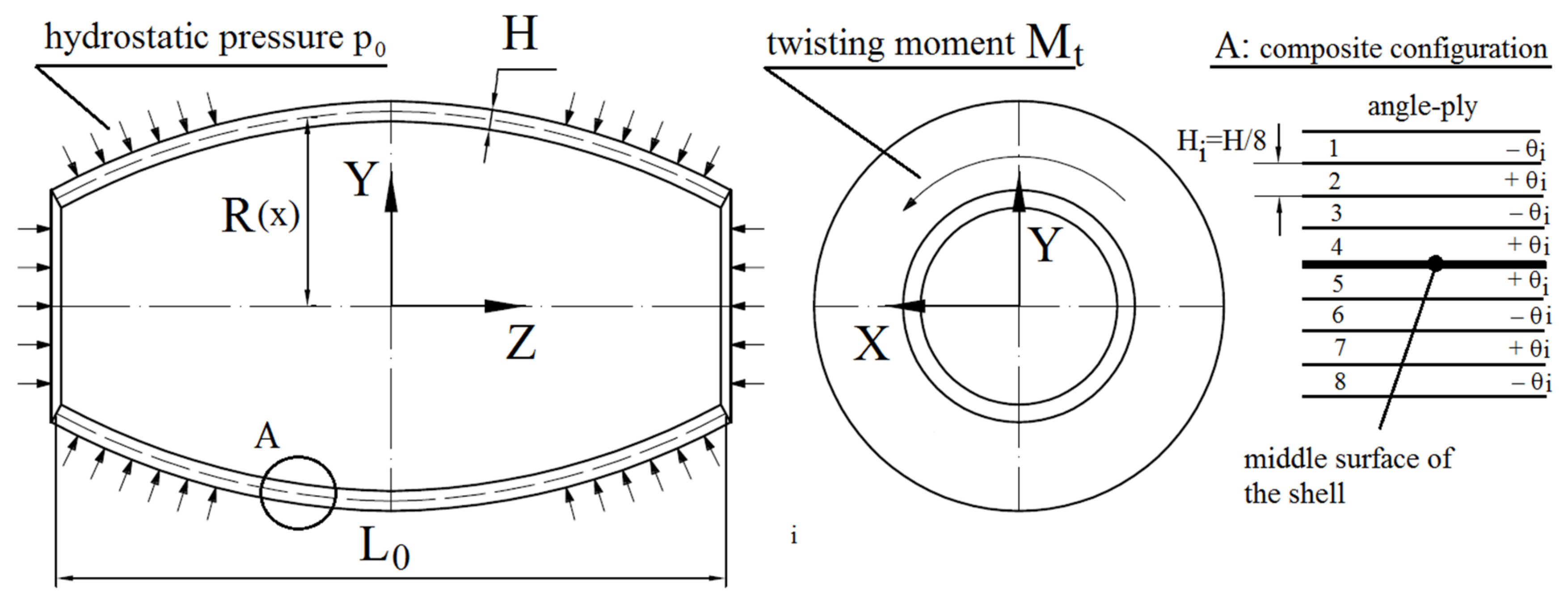
- The volume of the material of the optimal structure and reference shell is identical.
- The capacity of the optimal structure and reference shell is equal.
- The minimal radius at both ends of the shell is constrained by a lower bound, R(L0) > Radm.
- The slope of the meridian is limited by upper bound, |R′| ≤ Radm.
- The current study is limited to the convex shell (the positive Gaussian curvature), where R″ ≤ 0.
3. Methods of Finding Solution
3.1. Optimization Procedure
3.2. Numerical Model and Material Properties
4. Results
4.1. Composite Shell under Hydrostatic Pressure
4.2. Composite Shell under Twisting
4.3. Shell under Combined Loadings
5. Conclusions
- The proposed optimization technique, based on splitting the procedure into two steps (the shape of the middle surface and the layer configuration are optimized separately), gives considerable benefits in the case of anisotropic structures subjected to combined loadings, and allows for the determination of more optimal geometries for all investigated loading conditions.
- In the case of the isotropic structure under hydrostatic pressure, profit from optimization is the highest for structure, where μ = 0.5 and γ = 0.004. The obtained qmax/q0 ratio varies from 3.461 to 2.238.
- In the case of isotropic shells subjected to pure twisting the profit from optimization varies insignificantly (from 1.712 to 1.619) and is smaller in comparison with shells under hydrostatic pressure. A very slight impact of parameters μ and γ on final results is observed.
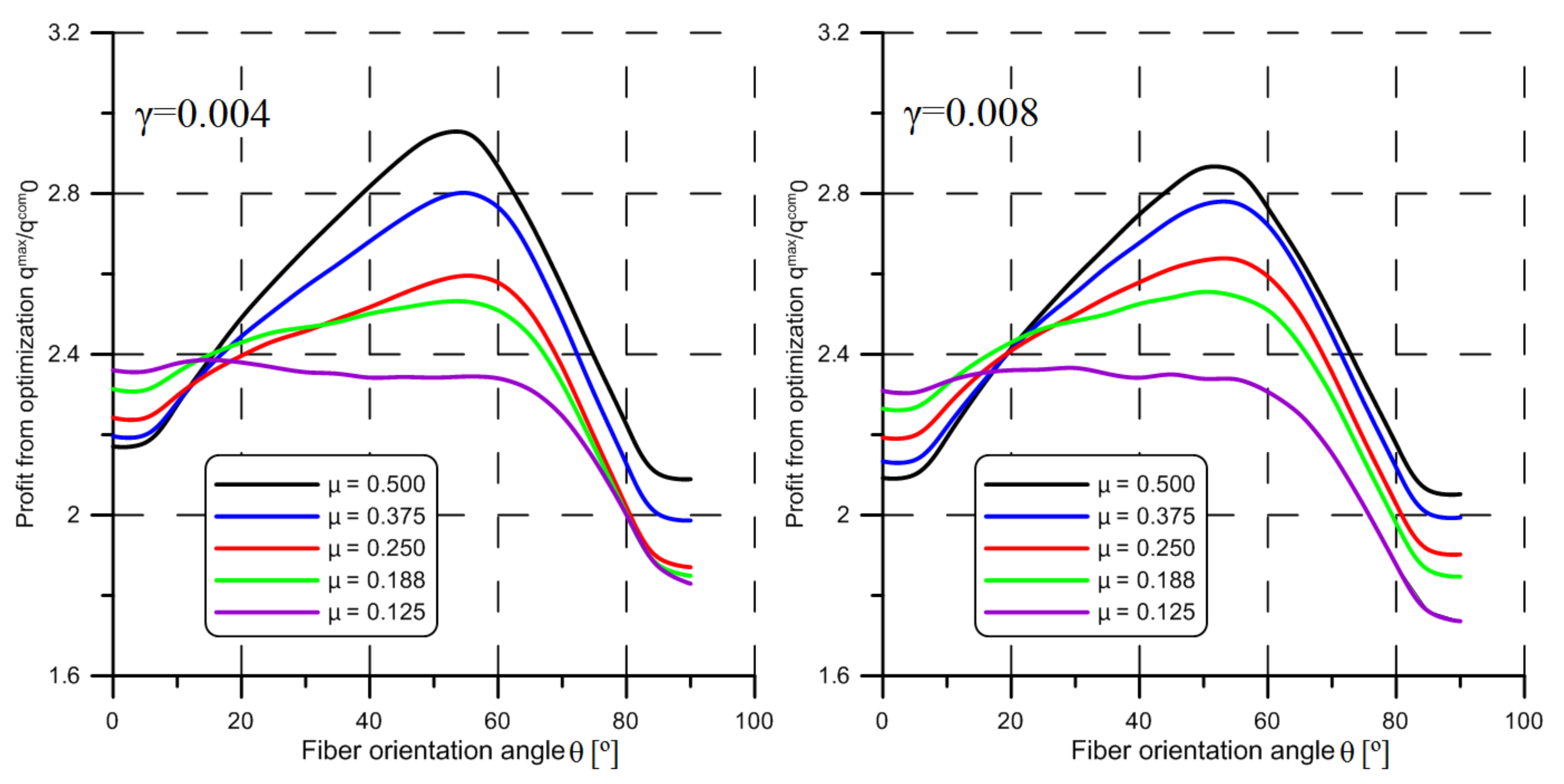
- Generally, in the case of composite shells, the profit from optimization is significantly higher as in the case of isotropic shells. For shells under hydrostatic pressure, the qmax/qcom0 ratio varies from 5.495 to 3.386 for E1/E2 = 17.573, and from 4.080 to 2.727 for ratio E1/E2 = 3.415. The value of parameters μ and γ as well as the E1/E2 ratio have a significant influence on the final results.
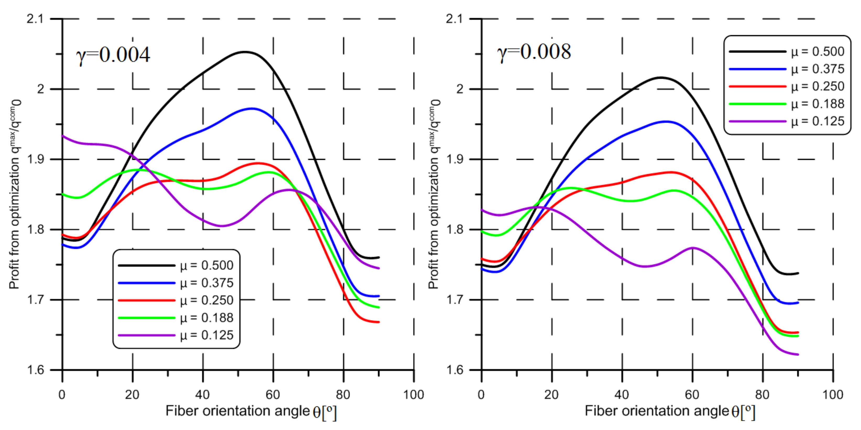
- For the composite shells subjected to twisting the impact of the parameters μ and γ are not significant except the E1/E2 ratio. The obtained results vary from 2.951 to 2.366 for E1/E2 = 17.573, and from 2.052 to 1.832 for E1/E2 = 3.415. A clear maximum in the relationship between qmax/qcom0 ratio and the fiber orientation angle θ is observed.
- In the case of structures subjected to combined load (external pressure and twisting), a significant profit of the application of the barrel-shaped shell is observed. A larger increase of this profit (qmax/qcom0 is from 5.359 to 2.951) is observed for shorter shells (γ = 0.004 and μ = 0.5). In the case of the longer shells, this profit is much smaller (from 3.386 to 2.366). Optimal fiber orientation angle θmax is significantly different in such cases.
- In the case of the structures, where the participation of twisting is significant, it seems to be a justified extension of the optimization procedure by the introduction of the variable thickness as the additional design variable.
Author Contributions
Funding
Institutional Review Board Statement
Informed Consent Statement
Data Availability Statement
Conflicts of Interest
Appendix A
Appendix B. Local Stability Condition and Shell of Uniform Stability
- First of all, the maximal value of critical load multiplied and the corresponding shape of the middle surface of the shell is determined with the use of Equations (A6), (A7), and (A24). The variable wall thickness is described by one of the expressions (A20), (A22), or (A23) depending on which case of the load is studied.
- The determined previously optimal shape of the middle surface is imported to the system of the finite element method. Next, the regular mesh, which consists of quadrilateral elements, is generated as shown in Figure 2. The size of the elements is assumed as le = L0/40.
- It is assumed that the thickness in each finite element is constant and its value is computed with the use of the expression (A20), (A22), or (A23) in the point where ξ = (ξi + ξi + 1)/2, i = 1,2, …, 40. Of course, the mentioned coordinates ξi and ξi + 1 describe the X coordinate of the nodes which create each following ring of finite elements. For all these elements the wall thickness H is identical.
- For such a finite element model the buckling analysis is performed. If the value of the obtained critical load multiplier is identical in comparison with the value computed with the use of analytical formulas described in Appendix B, which means that the analytical model provides reliable and accurate results.
| μ | q0·10−6 | qustb/q0 | qmes/q0 | n/n0 | r(0) | r(1) |
|---|---|---|---|---|---|---|
| γ = 0.004 | ||||||
| 0.500 | 2.500 | 3.953 | 3.961 | 70/16 | 1.137 | 0.702 |
| 0.375 | 2.162 | 3.934 | 3.945 | 74/14 | 1.216 | 0.500 |
| 0.250 | 1.773 | 3.547 | 3.573 | 42/10 | 1.216 | 0.500 |
| 0.188 | 1.517 | 3.233 | 3.263 | 30/10 | 1.216 | 0.500 |
| 0.125 | 1.223 | 2.750 | 2.791 | 20/8 | 1.216 | 0.500 |
| γ = 0.008 | ||||||
| 0.500 | 11.811 | 3.347 | 3.356 | 50/12 | 1.137 | 0.702 |
| 0.375 | 10.364 | 3.282 | 3.293 | 52/12 | 1.216 | 0.500 |
| 0.250 | 8.457 | 2.975 | 3.007 | 30/10 | 1.216 | 0.500 |
| 0.188 | 7.115 | 2.757 | 2.798 | 12/8 | 1.216 | 0.500 |
| 0.125 | 5.903 | 2.279 | 2.325 | 14/6 | 1.216 | 0.500 |
| μ | q0·10−6 | qustb/q0 | qmes/q0 | n/n0 | r(0) | r(1) |
|---|---|---|---|---|---|---|
| γ = 0.004 | ||||||
| 0.500 | 7.823 | 1.611 | 1.813 | 44/20 | 1.093 | 0.803 |
| 0.375 | 7.368 | 1.587 | 1.839 | 42/18 | 1.115 | 0.753 |
| 0.250 | 6.749 | 1.575 | 2.015 | 40/16 | 1.170 | 0.619 |
| 0.188 | 6.329 | 1.569 | 2.237 | 38/14 | 1.216 | 0.500 |
| 0.125 | 5.770 | 1.474 | 2.123 | 28/12 | 1.216 | 0.500 |
| γ = 0.008 | ||||||
| 0.500 | 33.552 | 1.502 | 1.669 | 30/16 | 1.093 | 0.803 |
| 0.375 | 31.668 | 1.487 | 1.762 | 30/14 | 1.126 | 0.728 |
| 0.250 | 29.129 | 1.468 | 1.928 | 30/12 | 1.181 | 0.590 |
| 0.188 | 27.334 | 1.453 | 2.081 | 28/12 | 1.216 | 0.500 |
| 0.125 | 24.928 | 1.365 | 1.978 | 20/10 | 1.216 | 0.500 |
References
- Pan, B.B.; Cui, W.C. An overview of buckling and ultimate strength of spherical pressure hull under external pressure. Mat. Struct. 2010, 23, 227–240. [Google Scholar] [CrossRef]
- Zingoni, A. Liquid-containment shells of revolution: A review of recent studies on strength, stability and dynamics. Thin Wall. Struct. 2015, 87, 102–114. [Google Scholar] [CrossRef]
- Błachut, J.; Magnucki, K. Strength, Stability, and optimization of pressure vessels: Review of selected problems. Appl. Mech. Rev. 2008, 61, 60801. [Google Scholar] [CrossRef]
- Liu, P.; Kaewunruen, S.; Zhou, D.; Wang, S. Investigation of the Dynamic Buckling of Spherical Shell Structures Due to Subsea Collisions. Appl. Sci. 2018, 8, 1148. [Google Scholar] [CrossRef]
- Błachut, J. Buckling of cylinders with imperfect length. J. Press. Technol. 2014, 137, 011203. [Google Scholar] [CrossRef]
- Xue, J. Local buckling in infinitely, long cylindrical shells subjected uniform external pressure. Thin Wall. Struct. 2012, 53, 211–216. [Google Scholar] [CrossRef]
- MacKay, J.R.; Van Keulen, F.; Smith, M.J. the accuracy of numerical collapse predictions for the design of submarine pressure hulls. Thin Wall. Struct. 2011, 49, 145–156. [Google Scholar] [CrossRef]
- Błachut, J. Buckling of externally pressurized steel toriconical shells. Int. J. Press.Vessel. Pip. 2016, 144, 25–34. [Google Scholar] [CrossRef]
- Zhang, J.; Zhang, M.; Tang, W.X.; Wang, W.B.; Wang, M.L. Buckling of spherical shells subjected to external pressure: A comparison of experimental and theoretical data. Thin Wall. Struct. 2017, 111, 58–64. [Google Scholar] [CrossRef]
- Błachut, J. Experimental perspective on the buckling of pressure vessel components. Appl. Mech. Rev. 2013, 66, 11003. [Google Scholar] [CrossRef]
- Sato, M.; Wadee, M.A.; Iiboshi, K.; Sekizawa, T.; Shima, H. Buckling patterns of complete spherical shells filled with an elastic medium under external pressure. Int. J. Mech. Sci. 2012, 59, 22–30. [Google Scholar] [CrossRef]
- Shakouri, M.; Kouchakzadeh, M.A. Analytical solution for vibration of generally laminated conical and cylindrical shells. Int. J. Mech. Sci. 2017, 131–132, 414–425. [Google Scholar] [CrossRef]
- Krysko, V.A.; Awrejcewicz, J.; Saveleva, N.E. Stability, bifurcation and chaos of closed flexible cylindrical shells. Int. J. Mech. Sci. 2008, 50, 247–274. [Google Scholar] [CrossRef]
- Thompson, J.; Michael, T. Advances in shell buckling: Theory and experiments. Int. J. Bifurc. Chaos 2015, 25, 1530001. [Google Scholar] [CrossRef]
- Arbocz, J.; Starnes, J.H. Future directions and challenges in shell stability analysis. Thin Wall. Struct. 2002, 40, 729–754. [Google Scholar] [CrossRef]
- Błachut, J. On optimal barrel ‒ shaped shells under buckling constraints. AIAA J. 1987, 25, 186–188. [Google Scholar]
- Błachut, J. Combined axial and pressure buckling of shells having optimal positive curvature. Comput. Struct. 1987, 26, 513–519. [Google Scholar] [CrossRef]
- Błachut, J. Buckling of externally pressurised barrelled shells: A comparison of experiment and theory. Int. J. Pres. Ves. Pip. 2002, 79, 507–517. [Google Scholar] [CrossRef]
- Błachut, J. Optimal barreling of steel shells via simulated annealing algorithm. Comp. Struct. 2003, 81, 1941–1956. [Google Scholar] [CrossRef]
- Jasion, P.; Magnucki, K. Elastic buckling of barrelled shell under external pressure. Thin Wall. Struct. 2007, 45, 393–399. [Google Scholar] [CrossRef]
- Jasion, P. Stability analysis of shells of revolution under pressure conditions. Thin Wall. Struct. 2009, 47, 311–317. [Google Scholar] [CrossRef]
- Jasion, P.; Magnucki, K. Elastic buckling of horizontal barrelled shells filled with liquid—Numerical analysis. Thin Wall. Struct. 2012, 52, 117–125. [Google Scholar] [CrossRef]
- Magnucki, K.; Jasion, P. Analytical description of pre-buckling and buckling states of barrelled shells under radial pressure. Ocean Eng. 2013, 58, 217–223. [Google Scholar] [CrossRef]
- Krużelecki, J.; Stawiarski, A. Optimal design of thin-walled columns for buckling under loadings controlled by displacements. Struct. Multidiscip. Optim. 2010, 42, 305–314. [Google Scholar] [CrossRef]
- Zhang, J.; Wang, M.; Wang, W.; Tang, W. Buckling of egg-shaped shells subjected to external pressure. Thin Wall. Struct. 2017, 113, 122–128. [Google Scholar] [CrossRef]
- Zhang, J.; Hua, Z.; Tang, W.; Wang, F.; Wang, S. Buckling of externally pressurised egg-shaped shells with variable and constant wall thickness. Thin Wall. Struct. 2018, 132, 111–119. [Google Scholar] [CrossRef]
- Zhang, J.; Tan, J.; Tang, W.; Zhao, X.; Zhu, Y. Experimental and numerical collapse properties of externally pressurized egg-shaped shells under local geometrical imperfections. Int. J. Pres. Ves. Pip. 2019. [Google Scholar] [CrossRef]
- Sowiński, K. Buckling of shells with special shapes with corrugated middle surfaces—FEM study. Eng. Struct. 2019, 179, 310–320. [Google Scholar] [CrossRef]
- Rezaiee-Pajand, M.; Masoodi, A.R. Shell instability analysis by using mixed interpolation. J. Braz. Soc. Mech. Sci. Eng. 2019, 41, 419. [Google Scholar] [CrossRef]
- Rezaiee-Pajand, M.; Arabi, E.; Masoodi, A.R. Nonlinear analysis of FG-sandwich plates an shells. Aerosp. Sci. Technol. 2019, 87, 178–189. [Google Scholar] [CrossRef]
- Życzkowski, M.; Krużelecki, J. Optimal design of shells with respect to their stability. In IUTAM Symposium on Optimization in Structural Design; Sawczuk, A., Mróz, Z., Eds.; Springer: Warsaw, Poland, 1973; Berlin/Heidelberg, Germany; New York, NY, USA, 1975; pp. 229–247. [Google Scholar]
- Krużelecki, J.; Trzeciak, P. Optimal design of axially symmetrical shells under hydrostatic pressure with respect to their stability. Struct. Multidisc. Optim. 2000, 19, 148–154. [Google Scholar] [CrossRef]
- Życzkowski, M.; Krużelecki, J.; Trzeciak, P. Optimal design of rotationally symmetric shells for buckling under thermal loadings. J. Appl. Mech. 2001, 39, 443–455. [Google Scholar]
- Barski, M.; Krużelecki, J. Influence of a shearing force on optimal design of shells against buckling under overall bending. Eng. Optim. 2004, 36, 439–455. [Google Scholar] [CrossRef]
- Barski, M.; Krużelecki, J. Optimal design of shells against buckling by means of the simulated annealing method. Struct. Multidisc. Optim. 2005, 29, 61–72. [Google Scholar] [CrossRef]
- Barski, M.; Krużelecki, J. Optimal design of shells against buckling under overall bending and external pressure. Thin Wall. Struct. 2005, 43, 1677–1698. [Google Scholar] [CrossRef]
- Barski, M. Optimal design of shells against buckling subjected to combined loadings. Struct. Multidisc. Optim. 2006, 31, 211–222. [Google Scholar] [CrossRef]
- Muc, A.; Chwał, M.; Barski, M. Remarks on experimental and theoretical investigations of buckling loads for laminated plated and shell structures. Compos. Struct. 2018, 203, 861–874. [Google Scholar] [CrossRef]
- Barski, M.; Romanowicz, P. Natural frequencies and modal shapes of composite cylindrical panels with local damages. In Shell Structures: Theory and Applications—Proceedings of the 10th SSTA 2013 Conference; Gdańsk, Poland, 16–18 October 2013, Pietraszkiewicz, W., Górski, J., Eds.; Taylor &Francis Group: London, UK, 2014; Volume 3, pp. 277–280. [Google Scholar]
- Muc, A.; Bondyra, A.; Romanowicz, P. Buckling of composite multilayered shells—An experimental analysis. In Shell Structures: Theory and Applications—Proceedings of the 10th SSTA 2013 Conference; Gdańsk, Poland, 16–18 October 2013, Pietraszkiewicz, W., Górski, J., Eds.; Taylor & Francis Group: London, UK, 2014; Volume 3, pp. 227–230. [Google Scholar]
- Muc, A.; Stawiarski, A.; Romanowicz, P. Experimental Investigations of Compressed Sandwich Composite/Honeycomb Cylindrical Shells. Appl. Compos. Mater. 2018, 25, 177–189. [Google Scholar] [CrossRef]
- Stawiarski, A.; Chwał, M.; Barski, M.; Muc, A. The influence of the manufacturing constraints on the optimal design of laminated conical shells. Compos. Struct. 2020, 235, 111820. [Google Scholar] [CrossRef]
- Muc, A.; Chwał, M.; Romanowicz, P.; Stawiarski, A. Fatigue-Damage Evolution of Notched Composite Multilayered Structures under Tensile Loads. J. Compos. Sci. 2018, 2, 27. [Google Scholar] [CrossRef]
- Muc, A. Peculiarities in the Material Design of Buckling Resistance for Tensioned Laminated Composite Panels with Elliptical Cut-Outs. Materials 2018, 11, 1019. [Google Scholar] [CrossRef]
- Verchery, G. Design rules for the laminate stiffness. Mech. Compos. Mater. 2011, 47, 47–58. [Google Scholar] [CrossRef]
- Muc, A.; Chwał, M. Analytical discrete stacking sequence optimization of rectangular composite plates subjected to buckling and FPF constraints. J. Theor. Appl. Mech. 2016, 54, 423–436. [Google Scholar] [CrossRef]
- Vlassov, V.S. Allgemeine Schalentheorie und ihre Anwendung in der Technik; Akademie‒Verlag: Berlin, Germany, 1958; (translated from Russian, Moskva‒Leningrad 1949). [Google Scholar]
- Shirshov, V.P. Local buckling of shells. Soviet Appl. Mech. 1966, 2, 77–78. [Google Scholar] [CrossRef]
- Bushnell, D. Computerized Buckling of Shells. Mechanics of Elastic Stability 9; Martinus Nijhoff Publishers: Dordrecht, The Netherlands, 1985. [Google Scholar]
- Muc, A. Mechanika Kompozytów Włóknistych; Księgarnia Akademicka: Kraków, Poland, 2003. [Google Scholar]
- Bere, P.; Nemes, O.; Dudescu, C.; Berce, P.; Sabau, E. Design and analysis of carbon/epoxy composite tubular parts. Adv. Eng. Forum 2013, 8–9, 207–214. [Google Scholar] [CrossRef]
- Papkovich, P.F. Stroitelnaya Mekhanika Korablya, Ch. 2. (Structural Mechanics of a Ship), Part 2; Gos. Soyuz. Izd. Sudostr. Promyshl: Leningrad, Russia, 1941. (in Russian) [Google Scholar]
- Axelrad, E.I. On local buckling of thin shells. Int. J. Non Linear Mech. 1985, 24, 249–259. [Google Scholar] [CrossRef]
- Grikmann, K. Flächentragwerke, Einführung in die Elastostatik der Scheiben, Platten, Schalen und Faltwerke; Springer: Berlin/Heidelberg, Germany, 1954. [Google Scholar]
- Flügge, W. Statik und Dynamik der Schalen; Springer: Berlin/Heidelberg, Germany, 1957. [Google Scholar]
- Trzeciak, P. Optimal Design of Axially-Symmetric Shells of Uniform Stability Subjected to Combined Loadings. Ph.D. Thesis, Cracow University of Technology, Kraków, Poland, 2006. (in Polish). [Google Scholar]



| Material | E1 [GPa] | E2 [GPa] | G12 [GPa] | ν12 | E1/E2 |
|---|---|---|---|---|---|
| steel | 210.0 | 210.0 | 80.77 | 0.30 | 1.000 |
| carbon fiber/epoxy resin | 181.0 | 10.3 | 7.17 | 0.28 | 17.573 |
| glass fiber/polyester resin | 28.0 | 8.2 | 2.80 | 0.29 | 3.415 |
| μ | q0·10−6 | qmax/q0 | qustb/q0 | h | n/n0 | r(0) | r(1) |
|---|---|---|---|---|---|---|---|
| γ = 0.004 | |||||||
| 0.500 | 2.500 | 3.461 | 3.767 | 0.937 | 36/16 | 1.115 | 0.753 |
| 0.375 | 2.162 | 3.476 | 3.693 | 0.938 | 32/14 | 1.159 | 0.647 |
| 0.250 | 1.773 | 3.570 | 3.547 | 0.961 | 28/10 | 1.216 | 0.500 |
| 0.188 | 1.517 | 3.220 | 3.233 | 0.987 | 30/10 | 1.216 | 0.500 |
| 0.125 | 1.223 | 2.670 | 2.750 | 1.007 | 20/8 | 1.216 | 0.500 |
| γ = 0.008 | |||||||
| 0.500 | 11.811 | 3.012 | 3.189 | 0.937 | 26/12 | 1.115 | 0.753 |
| 0.375 | 10.364 | 2.980 | 3.082 | 0.938 | 24/12 | 1.159 | 0.647 |
| 0.250 | 8.457 | 3.046 | 2.975 | 0.961 | 22/10 | 1.216 | 0.500 |
| 0.188 | 7.115 | 2.761 | 2.757 | 0.987 | 22/8 | 1.216 | 0.500 |
| 0.125 | 5.903 | 2.238 | 2.279 | 1.007 | 14/6 | 1.216 | 0.500 |
| μ | γ | Cylindrical Pipe | Optimal (Barrel) Shape | ||||
|---|---|---|---|---|---|---|---|
| qcom0·10−6 | qcomcyl/qcom0 | θcyl [°] 1 | qmax/qcom0 | θmax [°] 1 | n/n0 | ||
| 0.500 | 0.004 | 0.781 | 2.091 | 10 | 5.495 | 15 | 22/20 |
| 0.375 | 0.683 | 2.084 | 0 | 5.457 | 10 | 18/18 | |
| 0.250 | 0.569 | 2.028 | 0 | 5.460 | 0 | 16/16 | |
| 0.188 | 0.495 | 2.099 | 5 | 4.785 | 0 | 16/14 | |
| 0.125 | 0.411 | 1.996 | 0 | 3.903 | 0 | 10/12 | |
| 0.500 | 0.008 | 3.659 | 2.126 | 5 | 4.851 | 25 | 18/16 |
| 0.375 | 3.217 | 2.045 | 0 | 4.768 | 15 | 14/14 | |
| 0.250 | 2.655 | 2.065 | 5 | 4.723 | 0 | 12/12 | |
| 0.188 | 2.353 | 1.998 | 0 | 4.068 | 0 | 10/12 | |
| 0.125 | 1.938 | 2.189 | 10 | 3.386 | 0 | 8/10 | |
| μ | γ | Cylindrical Pipe | Optimal (Barrel) Shape | ||||
|---|---|---|---|---|---|---|---|
| qcom0·10−6 | qcomcyl/qcom0 | θcyl [°] 1 | qmax/qcom0 | θmax [°] 1 | n/n0 | ||
| 0.500 | 0.004 | 1.489 | 1.368 | 0 | 4.080 | 10 | 28/18 |
| 0.375 | 1.300 | 1.357 | 0 | 4.140 | 0 | 24/16 | |
| 0.250 | 1.053 | 1.377 | 0 | 4.354 | 0 | 22/12 | |
| 0.188 | 0.913 | 1.357 | 0 | 3.880 | 0 | 22/10 | |
| 0.125 | 0.741 | 1.423 | 0 | 3.210 | 0 | 16/10 | |
| 0.500 | 0.008 | 6.949 | 1.372 | 0 | 3.579 | 15 | 22/14 |
| 0.375 | 6.079 | 1.364 | 0 | 3.609 | 5 | 18/12 | |
| 0.250 | 5.001 | 1.348 | 0 | 3.719 | 0 | 16/10 | |
| 0.188 | 4.391 | 1.410 | 0 | 3.238 | 0 | 16/10 | |
| 0.125 | 3.552 | 1.345 | 0 | 2.727 | 0 | 12/8 | |
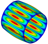
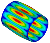
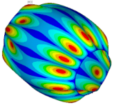
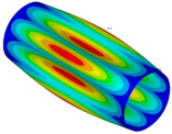
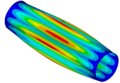
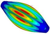
| Ref. Cylindrical Metal Shell | Optimal Metal Barrel Shell | Ref. Composite Cylindrical Shell θ = 90° | Optimal Composite Barrel Shell |
|---|---|---|---|
 |  |  |  |
| μ = 0.500 | |||
 |  |  |  |
| μ = 0.375 | |||
 |  |  |  |
| μ = 0.250 | |||
 |  |  |  |
| μ = 0.188 | |||
 |  |  |  |
| μ = 0.125 | |||
| μ | q0·10−6 | qmax/q0 | qustb/q0 | h | n/n0 | r(0) | r(1) |
|---|---|---|---|---|---|---|---|
| γ = 0.004 | |||||||
| 0.500 | 7.823 | 1.688 | 1.611 | 0.957 | 34/20 | 1.093 | 0.803 |
| 0.375 | 7.368 | 1.671 | 1.587 | 0.965 | 32/18 | 1.113 | 0.753 |
| 0.250 | 6.749 | 1.672 | 1.575 | 0.973 | 26/16 | 1.170 | 0.619 |
| 0.188 | 6.329 | 1.702 | 1.569 | 0.987 | 22/14 | 1.216 | 0.500 |
| 0.125 | 5.770 | 1.712 | 1.474 | 1.007 | 18/12 | 1.216 | 0.500 |
| γ = 0.008 | |||||||
| 0.500 | 33.552 | 1.638 | 1.502 | 0.957 | 24/16 | 1.093 | 0.803 |
| 0.375 | 31.668 | 1.619 | 1.487 | 0.959 | 22/14 | 1.126 | 0.728 |
| 0.250 | 29.129 | 1.623 | 1.468 | 0.970 | 18/12 | 1.182 | 0.590 |
| 0.188 | 27.334 | 1.651 | 1.453 | 0.987 | 16/12 | 1.216 | 0.500 |
| 0.125 | 24.928 | 1.651 | 1.365 | 1.007 | 14/10 | 1.216 | 0.500 |
| μ | γ | Cylindrical Pipe | Optimal (Barrel) Shape | ||||
|---|---|---|---|---|---|---|---|
| qcom0·10−6 | qcomcyl/qcom0 | θcyl [°] 1 | qmax/qcom0 | θmax [°] 1 | n/n0 | ||
| 0.500 | 0.004 | 2.535 | 1.695 | 20 | 2.951 | 55 | 38/24 |
| 0.375 | 2.428 | 1.666 | 15 | 2.802 | 55 | 36/22 | |
| 0.250 | 2.297 | 1.617 | 0 | 2.596 | 55 | 30/20 | |
| 0.188 | 2.209 | 1.589 | 0 | 2.531 | 55 | 24/18 | |
| 0.125 | 2.086 | 1.549 | 0 | 2.386 | 15 | 14/16 | |
| 0.500 | 0.008 | 10.083 | 1.715 | 25 | 2.864 | 50 | 28/18 |
| 0.375 | 10.245 | 1.695 | 20 | 2.777 | 55 | 26/18 | |
| 0.250 | 9.627 | 1.651 | 15 | 2.636 | 55 | 22/16 | |
| 0.188 | 9.262 | 1.612 | 10 | 2.555 | 50 | 16/14 | |
| 0.125 | 8.775 | 1.581 | 0 | 2.366 | 30 | 10/12 | |
| μ | γ | Cylindrical Pipe | Optimal (Barrel) Shape | ||||
|---|---|---|---|---|---|---|---|
| qcom0·10−6 | qcomcyl/qcom0 | θcyl [°] 1 | qmax/qcom0 | θmax [°] 1 | n/n0 | ||
| 0.500 | 0.004 | 4.552 | 1.238 | 0 | 2.052 | 50 | 36/22 |
| 0.375 | 4.362 | 1.233 | 0 | 1.972 | 55 | 34/20 | |
| 0.250 | 4.100 | 1.221 | 0 | 1.894 | 55 | 28/18 | |
| 0.188 | 3.911 | 1.214 | 0 | 1.885 | 20 | 20/16 | |
| 0.125 | 3.602 | 1.214 | 0 | 1.933 | 0 | 16/14 | |
| 0.500 | 0.008 | 19.259 | 1.244 | 20 | 2.016 | 50 | 26/16 |
| 0.375 | 18.368 | 1.240 | 0 | 1.952 | 50 | 24/16 | |
| 0.250 | 17.280 | 1.232 | 0 | 1.881 | 55 | 20/14 | |
| 0.188 | 16.562 | 1.219 | 0 | 1.859 | 25 | 16/12 | |
| 0.125 | 15.539 | 1.207 | 0 | 1.832 | 15 | 12/12 | |
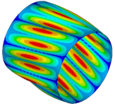
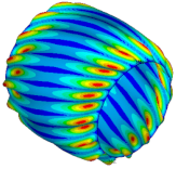
| Ref. Cylindrical Metal Shell | Optimal Metal Barrel Shell | Ref. Composite Cylindrical Shell θ = 90° | Optimal Composite Barrel Shell |
|---|---|---|---|
 |  |  |  |
| μ = 0.500 | |||
 |  |  |  |
| μ = 0.375 | |||
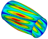 |  |  | 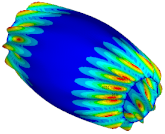 |
| μ = 0.250 | |||
 |  | 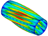 |  |
| μ = 0.188 | |||
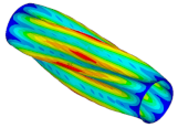 |  | 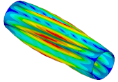 | 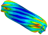 |
| μ = 0.125 | |||
| mt | Cylindrical Pipe | Optimal (Barrel) Shape: rC = r(ξ = 0) = 1.115, r(ξ = 1) = 0.753, m = 0.325 | Optimal (Barrel) Shape: rC = r(ξ = 0) = 1.093, r(ξ = 1) = 0.803, m = 0.265 | ||||
|---|---|---|---|---|---|---|---|
| qcom0·10−6 | qcomcyl/qcom0 | θcyl [°] | qmax/qcom0 | θmax [°] 1 | qmax/qcom0 | θmax [°] 1 | |
| 0 | 0.781 | 2.090 | 10 | 5.495 | 15 | 5.359 | 10 |
| 0.5 | 0.780 | 2.088 | 10 | 5.221 | 20 | 5.109 | 15 |
| 1 | 0.778 | 2.085 | 10 | 4.988 | 55 | 4.865 | 60 |
| 2 | 0.770 | 2.069 | 5 | 4.616 | 55 | 4.542 | 60 |
| 5 | 0.722 | 1.960 | 10 | 3.872 | 55 | 3.853 | 55 |
| 9 | 0.646 | 1.892 | 15 | 3.476 | 55 | 3.485 | 55 |
| 15 | 0.555 | 1.820 | 15 | 3.249 | 55 | 3.274 | 55 |
| 25 | 0.460 | 1.764 | 15 | 3.101 | 55 | 3.135 | 55 |
| ∞-Pure twisting | 2.535 | 1.695 | 20 | 2.916 | 50 | 2.951 | 55 |
| mt | Cylindrical Pipe | Optimal (Barrel) Shape: rC = r(ξ = 0) = 1.216, r(ξ = 1) = 0.500, m = 0.589 | |||
|---|---|---|---|---|---|
| qcom0·10−6 | qcomcyl/qcom0 | θcyl[°] 1 | qmax/qcom0 | θmax [°] 1 | |
| 0 | 1.938 | 2.189 | 10 | 3.386 | 0 |
| 0.5 | 1.937 | 2.189 | 10 | 3.385 | 0 |
| 1 | 1.936 | 2.186 | 10 | 3.383 | 0 |
| 2 | 1.929 | 2.180 | 5 | 3.372 | 0 |
| 5 | 1.891 | 2.100 | 0 | 3.302 | 0 |
| 9 | 1.808 | 1.956 | 0 | 3.146 | 0 |
| 15 | 1.669 | 1.825 | 0 | 2.913 | 0 |
| 25 | 1.466 | 1.724 | 0 | 2.678 | 15 |
| ∞-Pure twisting | 8.775 | 1.581 | 0 | 2.366 | 30 |
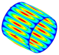
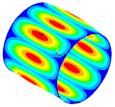
| Ref. Composite Cylindrical Shell θ = 90° | Optimal. Composite Cylindrical Shell | Optimal Composite Barrel Shell |
|---|---|---|
 |  |  |
| mt = 0.5 | ||
 | 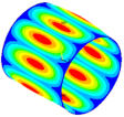 |  |
| mt = 1 | ||
 |  |  |
| mt = 2 | ||
 | 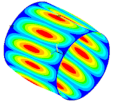 |  |
| mt = 5 | ||
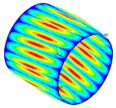 |  |  |
| mt = 15 | ||
Publisher’s Note: MDPI stays neutral with regard to jurisdictional claims in published maps and institutional affiliations. |
© 2021 by the authors. Licensee MDPI, Basel, Switzerland. This article is an open access article distributed under the terms and conditions of the Creative Commons Attribution (CC BY) license (https://creativecommons.org/licenses/by/4.0/).
Share and Cite
Barski, M.; Romanowicz, P.J.; Chwał, M.; Stawiarski, A. Parametric Optimization of Isotropic and Composite Axially Symmetric Shells Subjected to External Pressure and Twisting. J. Compos. Sci. 2021, 5, 128. https://doi.org/10.3390/jcs5050128
Barski M, Romanowicz PJ, Chwał M, Stawiarski A. Parametric Optimization of Isotropic and Composite Axially Symmetric Shells Subjected to External Pressure and Twisting. Journal of Composites Science. 2021; 5(5):128. https://doi.org/10.3390/jcs5050128
Chicago/Turabian StyleBarski, Marek, Paweł J. Romanowicz, Małgorzata Chwał, and Adam Stawiarski. 2021. "Parametric Optimization of Isotropic and Composite Axially Symmetric Shells Subjected to External Pressure and Twisting" Journal of Composites Science 5, no. 5: 128. https://doi.org/10.3390/jcs5050128
APA StyleBarski, M., Romanowicz, P. J., Chwał, M., & Stawiarski, A. (2021). Parametric Optimization of Isotropic and Composite Axially Symmetric Shells Subjected to External Pressure and Twisting. Journal of Composites Science, 5(5), 128. https://doi.org/10.3390/jcs5050128


