Article

Fabrication of Porous Carbon Films and Their Impact on Carbon/Polypropylene Interfacial Bonding

1
School of Forestry and Wildlife Sciences, Auburn University, 602 Duncan Drive, Auburn, AL 36849, USA
2
Department of Materials Science and Engineering, Clemson University, 161 Sirrine Hall, Clemson, SC 29634, USA
*
Authors to whom correspondence should be addressed.
J. Compos. Sci. 2021, 5(4), 108; https://doi.org/10.3390/jcs5040108
Submission received: 22 March 2021 / Revised: 7 April 2021 / Accepted: 9 April 2021 / Published: 14 April 2021
(This article belongs to the Special Issue Carbon Fiber Composites)

Abstract

:
Porous carbon films were generated by thermal treatment of polymer films made from poly(acrylonitrile-co-methyl acrylate)/polyethylene terephthalate (PAN/PET) blend. The precursor films were fabricated by a dip-coating process using PAN/PET solutions in hexafluoro-2-propanol (HFIP). A two-step process, including stabilization and carbonization, was employed to produce the carbon films. PET functioned as a pore former. Specifically, porous carbon films with thicknesses from 0.38–1.83 μm and pore diameters between 0.1–10 μm were obtained. The higher concentrations of PET in the PAN/PET mixture and the higher withdrawal speed during dip-coating caused the formation of larger pores. The thickness of the carbon films can be regulated using the withdrawal speed used in the dip-coating deposition. We determined that the deposition of the porous carbon film on graphite substrate significantly increases the value of the interfacial shear strength between graphite plates and thermoplastic PP. This study has shown the feasibility of fabrication of 3D porous carbon structure on the surface of carbon materials for increasing the interfacial strength. We expect that this approach can be employed for the fabrication of high-performance carbon fiber-thermoplastic composites.

1. Introduction

The increasing utilization of carbon fiber reinforced polymer composites (CFRPC), especially thermosetting polymers, has raised environmental and economic awareness for the need to recycle the composites [1,2,3,4,5,6,7]. To this end, employment of polyolefins for fabrication of advanced and recyclable carbon fiber reinforced thermoplastic composites (CFRTCs) possessing high solvent/environmental resistance, high modulus, strength, and toughness, can relieve the economic, environmental, and political pressure [8,9,10,11,12,13,14,15,16,17,18,19]. Lightweight CFRTCs already demonstrate great potential for automobile, aerospace, defense sectors, civil infrastructures, sport/leisure goods, and energy sector [1,5,6,12,20,21,22]. However, the key challenge remaining in the fabrication of advanced CFRTCs is poor interfacial bonding between fiber surface and polyolefins (exemplified by the most extensively explored polypropylene). The low adhesion level originates from low surface energy and the inert surface of carbon fibers (CFs) made from highly crystallized graphitic basal planes [20,21,22,23,24,25,26,27,28,29,30,31,32,33,34,35,36,37,38,39,40,41,42].
Several chemical and physical strategies are being explored to increase the interfacial adhesion between the CFs and polypropylene (PP). This includes the functionalization of PP with polar/reactive functional moieties and/or surface modification of CF such as oxidation, plasma and ozone treatment, thermal treatments, sizing, coupling agent treatments, and micro/nanofiber deposition, including whiskerization [23,24,25,26,27,28,29,30,31,32,43]. The latter methods of CF surface modification, where a change of surface topography/morphology of the fiber is targeted, employ mechanical interlocking to considerably increase the interlaminar shear strength (ILSS) of the resulting carbon fiber composites [31,32,43,44]. The mechanical anchoring diminishes the relative sliding between the CF and polymer matrix and improves stress transfer between the fiber and matrix, leading to higher modulus and strength. Thus, the properties of CFRTCs can be significantly improved via manipulation of the interfacial geometry. The interlocking approach appears to be quite universal in respect to polymer matrices used, as long as polymer material can impregnate the deposited fibrous surface structures. The main challenges remaining for the approach are complexity/sophistication of the morphological modification of CF exterior, mechanical robustness and uniformity of the fibrous layer deposited, effective impregnation of the layer with thermoplastic (e.g., PP) melt of high viscosity, and decrease of mechanical strength of CF as a result of the modification.
To this end, we have been developing an original surface modification method for carbon graphitic surfaces (such as the ones of carbon fibers) to create a non-fibrous mechanically anchoring robust carbon-based boundary. Specifically, our focus is on the fabrication of three-dimensional (3D) micrometric porous carbon structures attached to the carbon substrate surface. A 3D micromechanical interlocking interphase between carbon materials and a thermoplastic polymer is built during the composite manufacturing process through the infiltration of polymer melt into the pores created on carbon’s surface, leading to improvement of interfacial shear strength. The 3D micromechanical interlocking interphase has been designed to equate the stress at the carbon/polymer interface to the stress in the continuous phase of the polymer component when external shear/tension forces are applied to the composites. In this case, the maximum interfacial shear stress that can be sustained is determined by the strength of the polymer matrix.
The porous anchoring layer formation is conducted in just two straightforward steps: deposition of polymeric precursor on carbon surface and carbonization of the precursor layer. The deposition of carbon precursor is conducted from a solvent using a dip-coating procedure that can be realized in a conventional industrial setting. The carbonization is conducted using the same protocols as those typically used to obtain CF from polyacrylonitrile (PAN) fibers. In essence, to obtain the porous carbon coatings, we followed here procedures previously reported by us elsewhere [45]. In brief, it was found that crack-free carbon films with nanoscale roughness and controllable thickness can be produced by high-temperature treatment of the PAN-based film fabricated through dip-coating from 1,1,1,3,3,3-hexafluoro-2-propanol (HFIP) solution. The same basic procedure was used to form porous carbon films with tunable porous structure when PAN and polyethylene oxide (PEO) blend was used instead of PAN. PEO functioned as the pore-forming component in the precursor and carbon films, whose pore diameter could be varied from hundreds of nanometers to micrometers. However, PEO was not the ideal pore-forming polymer since it has relatively low glass transition and melting temperatures and is in a viscous molten state at the temperature of PAN stabilization. Thus, while carbon film obtained had significant internal porosity, surface porosity was relatively low [45].
In the current work, we replaced PEO with polyethylene terephthalate (PET), which has a melting temperature of about 265 °C [46] and does not flow at the temperature used for PAN stabilization. The PET’s employment allowed us to produce carbon films with the open-pore structure suitable to serve as the porous anchoring layer, connecting the polymer matrix and CF via the interlocking mechanism. The initial 3D micrometric porous carbon structure development and characterization were performed on silicon wafers. The porous carbon structure was then fabricated on the surfaces of graphite plates using the protocols developed for depositing porous carbon structure on the silicon wafers. Finally, the inter-laminar shear strength for PP/carbon interface was measured for graphite substrates using a lap-shear test. It was determined that ILSS increased ~70% when the porous coating was deposited on graphite plates.

2. Materials and Methods

2.1. Materials

Poly(acrylonitrile-co-methyl acrylate) (PAN, Mw = 100,000 g/mol) with 94 wt.% of acrylonitrile and polyethylene terephthalate (PET, MV = 18,000 g/mol) were purchased from Sigma-Aldrich (St. Louis, MO, USA). 1,1,1,3,3,3-hexafluoro-2-propanol (HFIP) was obtained from Oakwood Chemical (West Columbia, SC, USA). Silicon wafers with one highly polished side were obtained from WRS Materials (Spring City, PA, USA). Homopolymer polypropylene (PP) grafted with 1 wt.% maleic anhydride with a melt flow index of 115 g/10 min at 2.16 kg/190 °C was purchased from Addivant (Danbury, CT, USA). The melting point of the PP is reported as 160–170 °C. High-density graphite plates (1.91 g/cm3) were provided by Toyo Tanso USA, Inc. (Durham, CT, USA).

2.2. Polymer Solution Preparation

PAN solution in HFIP at the concentration of 3 wt.% was prepared by dissolving PAN in HFIP at room temperature. PAN/PET solutions were prepared by dissolving both polymers in HFIP at room temperature. The concentration of PAN/PET solutions represents the total weight of PAN and PET in the solution. Six solutions having 3 wt.% concentration with PAN/PET weight ratios of 60:40, 65:35, 70:30, 75:25, 80:20, and 90:10 were prepared.

2.3. Precursor Polymer Film Preparation

A dip-coating process was employed to deposit a polymer film from the solution on the silicon wafers using dip-coater D-3400 (Mayer Feintechnik, Göttingen, Germany). Before the dip-coating, silicon wafers were first cleaned in D.I. (deionized) water for one hour using an ultrasonic bath, then placed in a piranha solution (3:1 concentrated sulfuric acid/30% hydrogen peroxide) at 80 °C and sonicated for one hour, and finally rinsed several times with D.I. water. In the dip-coating process, two limiting withdrawal speeds of the equipment (25 and 250 mm/min) were used. All depositions were performed after ultrasonic treatment of the polymer solutions for about 10 min to remove air bubbles. After the dip-coating, the samples were placed under a hood in an ambient environment for three days to dry. The typical dimensions of the polymer films produced were 1 cm × 2 cm.
The following sample nomenclature used in this study is shown in Table 1. For PAN films, the first number after “PAN“ shows the solution concentration and the second number indicates the dip-coating withdrawal speed. For example, PAN-3-25 is used to denote the sample of PAN film produced from a 3 wt.% solution at a dip-coating speed of 25 mm/min. The sample name for polymer films of PAN/PET prepared from 3 wt.% solution starts with PAN/PET followed by the weight percentage of PET in the total polymer weight and then the dip-coating withdrawal speed. For instance, PAN/PET film obtained at a dip-coating withdrawal speed of 25 mm/min with the weight ratio of PAN to PET of 90:10 was labeled as PAN/PET-10-25.

2.4. Carbon Film Fabrication

The two-step carbonization procedure previously reported by us was employed here [45]. The films of PAN and PAN/PET were first thermally stabilized under air in an oven. The oven temperature was raised from 30–230 °C at a heating rate of 3 °C/min, held at 230 °C for 6 h, and then cooled down to room temperature. A high-temperature carbonization treatment was applied to the thermally stabilized films under a stream of ultrahigh purity nitrogen. The temperature was raised from 30 °C at a heating rate of 3 °C/min to 600 °C and then was subsequently heated to 1000 °C at a heating rate of 10 °C/min. The temperature was kept at 1000 °C for 30 min. The films were finally cooled down to room temperature in nitrogen.

2.5. Materials Characterization

Characterization of the films followed the procedures used in our previous study reported elsewhere [45]. The surface morphologies of the polymer films, stabilized films, and carbon films were characterized by atomic force microscopy (AFM) and scanning electron microscopy (SEM). AFM Dimension™ 3100 (Digital Instruments Inc., Tonawanda, NY, USA) in tapping mode was used to image the surface topography. NSC16 type silicon probes (MikroMasch) with a resonance frequency ~170 kHz, a spring constant ~45 N/m, and a tip radius of 8–10 nm were used. Imaging was performed at a scan rate of 1 Hz for pure PAN films and 0.5 Hz for PAN/PET films. A high-resolution scanning electron microscope (S4800 Hitachi, Tokyo, Japan) was used for the surface and fracture morphologies characterization. Before the SEM examination, the samples were coated with platinum. SEM images were obtained at an accelerating voltage of 10 kV at various magnifications. The thicknesses of the polymer films, stabilized films, and carbon films were determined by AFM cross-sectional measurements using the scratch method [47]. Scratches were formed on the polymer films by a razor blade. The same scratches were used to measure the thickness of the stabilized and carbonized films.

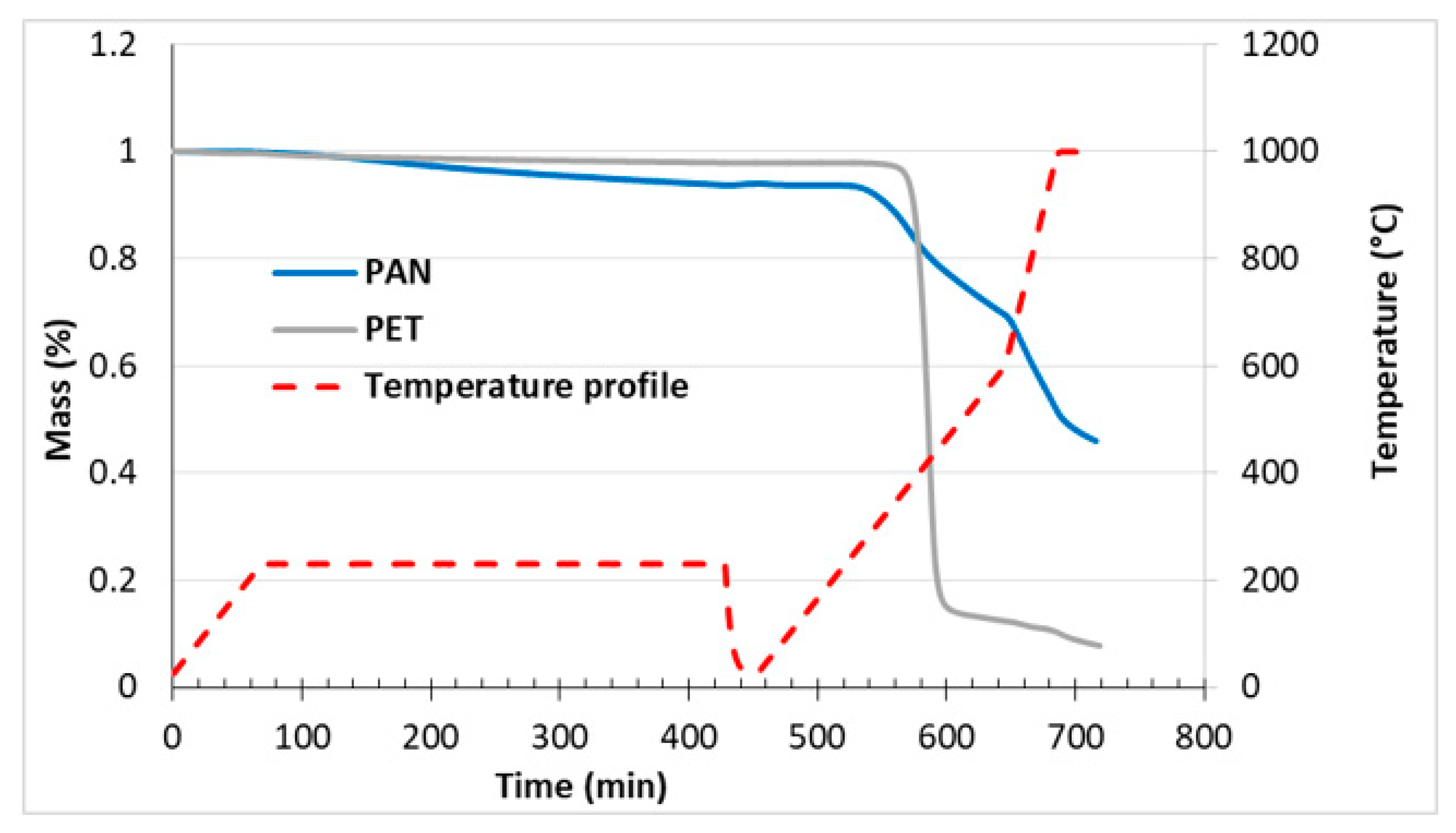
2.6. Thermogravimetric Analysis

Thermogravimetric analysis (TGA) of PAN and PET was conducted on an analyzer of Q500 from TA Instruments (New Castle, DE, USA). The TGA analysis was performed using the conditions simulating the two-step thermal treatment process. The TGA steps were specified as follows: (1) raise the temperature from 30–230 °C in air at 3 °C/min, (2) stay at 230 °C for 6 h in air, (3) cooldown to 30 °C in air, (4) raise the temperature from 30–600 °C at 3 °C/min in nitrogen, (5) raise the temperature from 600–1000 °C at 10 °C/min in nitrogen, and (6) stay at 1000 °C for 30 min.

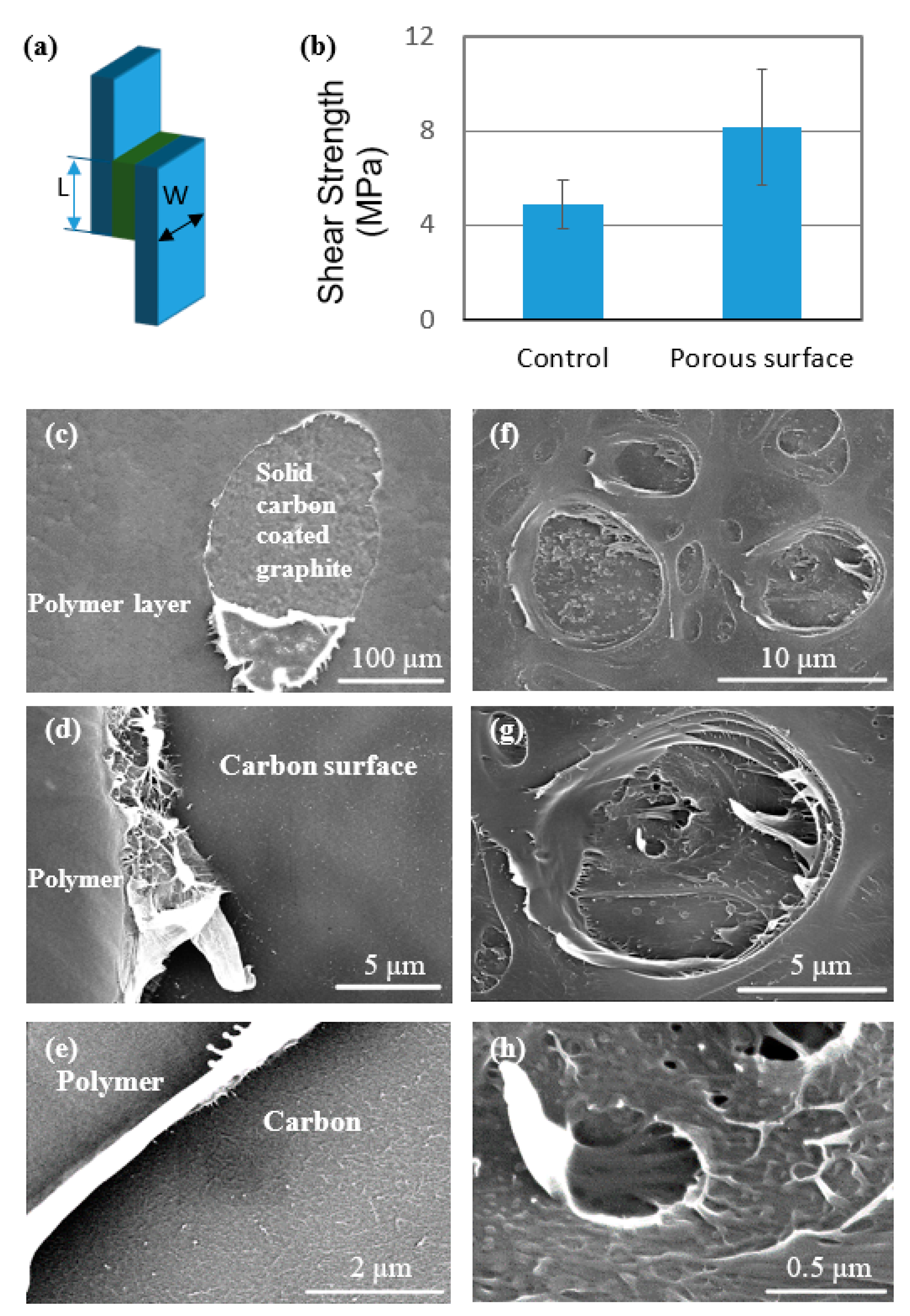
2.7. Interlaminar Shear Strength Measurement

Graphite plates coated with solid and porous carbon films were used in this part of our study. The dip-coating and carbonization procedures were the same as the ones used for the model silicon wafer substrates. Before the dip-coating, graphite plates (2.5 cm × 2 cm) were cleaned using the HFIP solvent. PAN and PAN/PET solutions with the PAN to PET ratio of 65:35 were used in the dip-coating process at the withdrawal speed of 250 mm/min. Initial bonding of the graphite plates coated with the carbon films was performed in a vacuum oven. Inside the oven, PP pellets were placed between the two graphite plates with a vacuum applied at the beginning of the consolidation process. The temperature was raised to 200 °C to melt the PP, and the assembly was kept at 200 °C for 30 min. Then, the two graphite plates with molten PP in between were transferred to a laboratory hot press set at 200 °C and low pressure (less than 0.7 MPa) was applied to fabricate a uniform PP layer between the plates. The bonding area was 2 cm × 2 cm, and 5 specimens for each sample group were prepared. The single lap-joint test was performed using an Instron machine (Model 5582) in compression mode at a loading head motion rate of 1 mm/min. The interlaminar shear strength is reported. The fracture interface between the two graphite plates was then characterized using a high-resolution scanning electron microscope (S4800 Hitachi). Before the SEM examination, the fracture surfaces were coated with platinum. SEM images were obtained at an accelerating voltage of 10 kV at various magnifications.

3. Result and Discussion

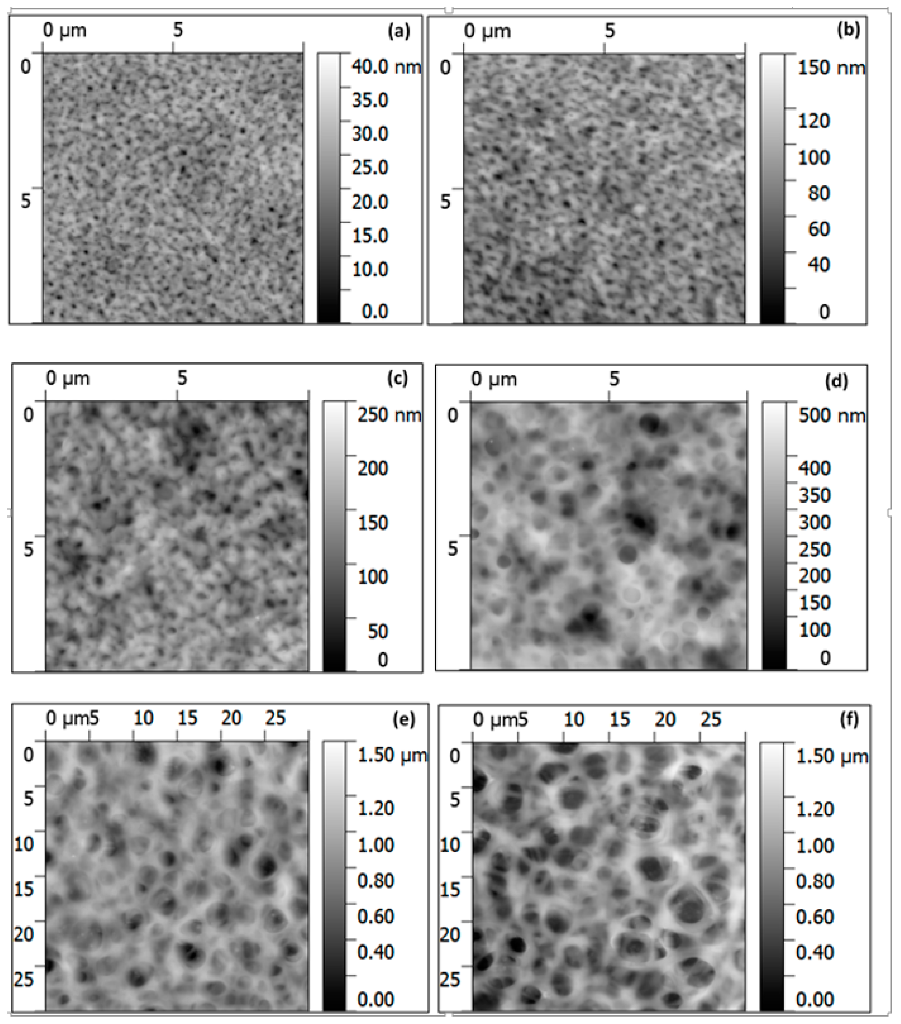
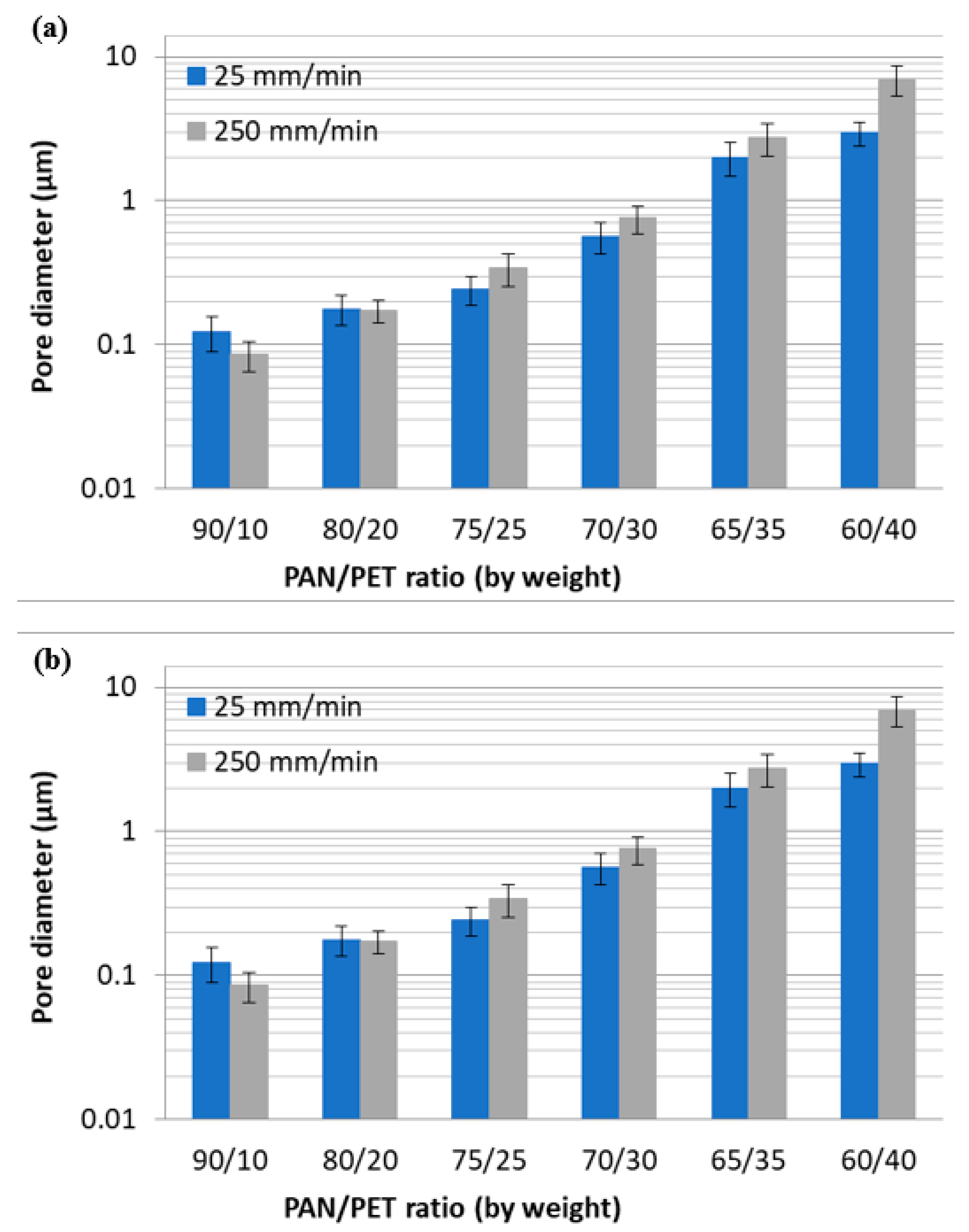
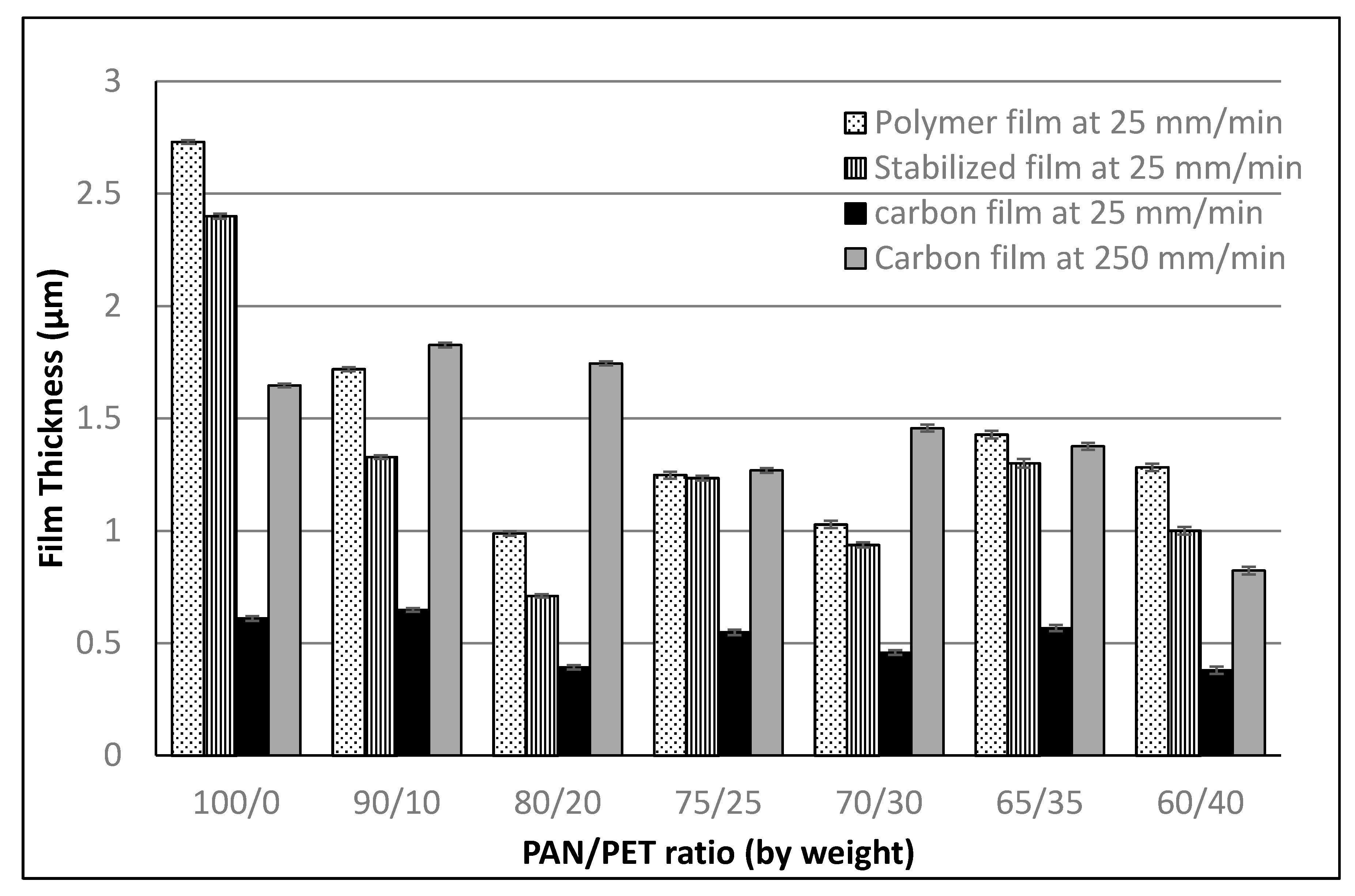
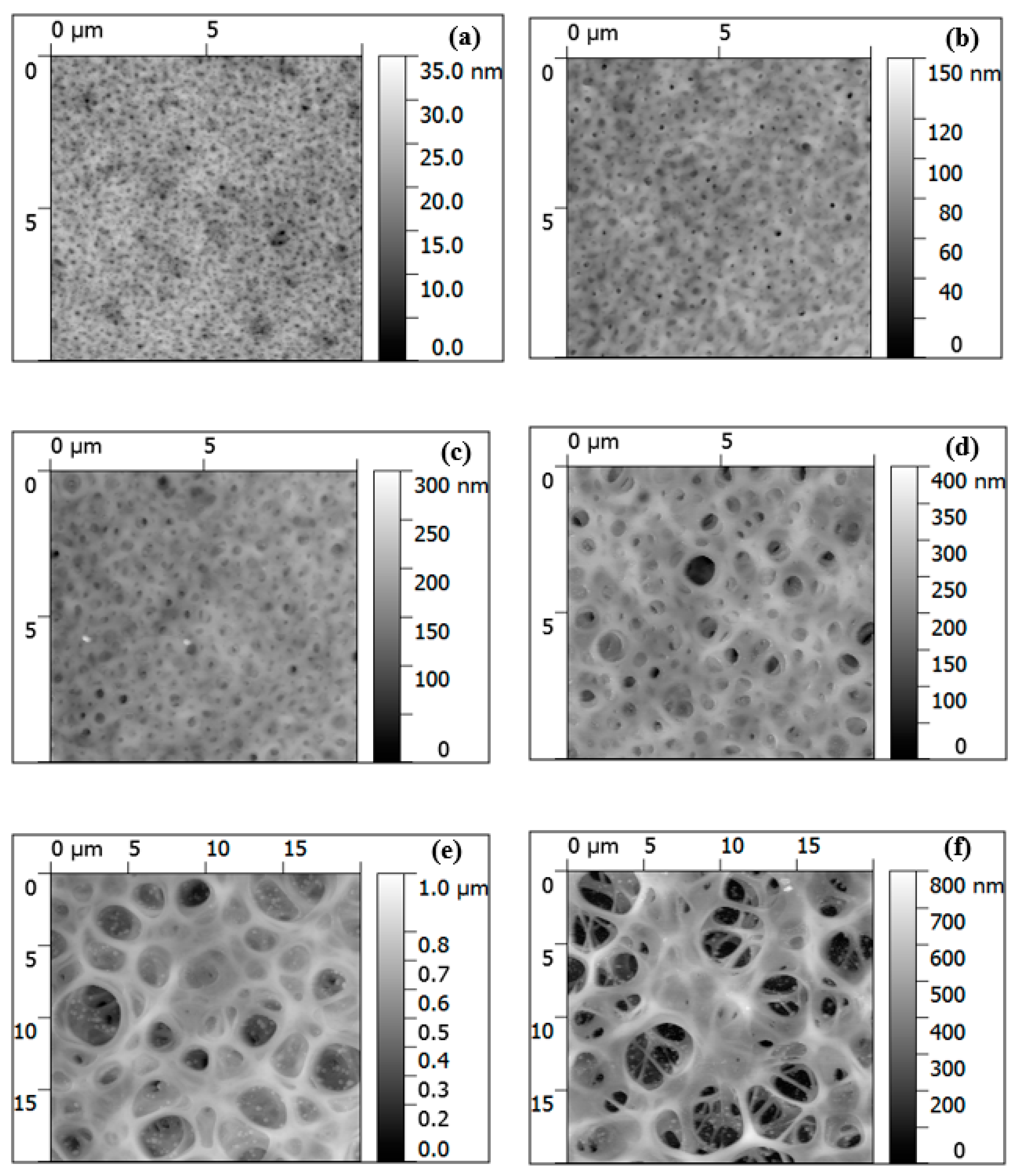
3.1. Fabrication and Morphology of Polymer Films

To obtain films from a binary polymer blend via a controllable and reproducible solvent-based process (such as dip-coating employed in this work), both polymers must be soluble in a solvent. It is also required that no phase separation occurs when the polymers are dissolved in the solvent simultaneously. One-component PAN and PET solutions in HFIP are visually clear, and the solid films obtained from the solution are optically transparent and uniform. The result indicated significant PAN and PET solubility in the solvent. The binary PAN/PET solutions were also transparent and homogeneous at the concentrations used here (PAN to PET ratio from 90:10 to 60:40), indicating good solubility of the polymer mixture in the solvent at 3 wt.%. Thus, PET could be added to the PAN solution to generate pores in the carbon films in the course of the high-temperature carbonization process.
Due to drying, the PAN/PET films at the PAN to PET ratios of 75:25, 70:30, 65:35, and 60:40 lost their transparency. The opaqueness of films suggested that phase separation occurred in these films. At the same time, the films with the PAN to PET ratios of 90:10 and 80:20 remained visually transparent. To further characterize the morphology of the PET/PAN films, their surface was visualized with AFM. Figure 1 shows the images for the films obtained by the dip-coating at the withdrawal speed of 25 mm/min followed by drying. One can see that, for all PET concentrations, circular pores formed within the films. The porous structure formation is associated with the different affinity of phases separating PAN and PET to the solvent [45]. Specifically, the pore formation indicates that the PAN matrix is more rapidly depleted of the solvent and solidifies before the solidification of the PET phase, which has a higher affinity to the solvent [48,49]. When a withdrawal speed of 250 mm/min is used, the films’ morphology was practically the same at the qualitative level (images are not shown). However, at higher PET content, the pores’ size is somewhat larger for the PET/PAN films obtained at a withdrawal speed of 250 mm/min. We suggest that the formation of larger pores can be caused by the deposition of a thicker swollen polymer film on the surface of the substrate at the higher dip-coating withdrawal speed (as discussed in the sections below). For the thicker film, it takes longer for the solvent to evaporate, and, therefore, larger PET domains can form during the phase separation process.
For both withdrawal speeds, the pore size increased with PET concentration. The diameter of the pores was estimated from AFM images (Figure 2a). At PAN/PET ratios of 90:10 and 80:20, the pores at both dip-coating withdrawal speeds were smaller than 220 nm in diameter, and, therefore, the films appeared transparent after drying. With the increase of PET concentration, the pore size increased to about 242 nm, 563 nm, 2 μm, to 3 μm for films having the PAN to PET ratios of 75:25, 70:30, 65:35, and 60:40, respectively, fabricated at the withdrawal speed of 25 mm/min. For a withdrawal speed of 250 mm/min, the pore sizes were 340 nm, 755 nm, 2.74 μm, and 7 μm for films with the PAN to PET ratios of 75:25, 70:30, 65:35, and 60:40, respectively. Our results indicate that the porous structure’s parameters can be varied via PET concentration and the withdrawal speed in a certain range.
The thicknesses of polymer films obtained were measured using AFM (Figure 3). For the films fabricated using the speed of 250 mm/min, all the polymer films had thicknesses higher than the vertical limit of our AFM (6.42 μm), and, thus, the thicknesses were not determined. Therefore, the data is reported for the films obtained using the lower withdrawal speed. The pure PAN film had a thickness of 2.73 μm. The PAN/PET films produced in this study had significantly lower thicknesses than that of the PAN film. The blended films’ thicknesses with 10, 20, 25, 30, 35, and 40 wt.% of PET were 1.72, 1, 1.25, 1.03, 1.43, and 1.28 μm, respectively. The decrease of the thickness is associated with the decrease of the solution viscosity as part of PAN is replaced with PET. Indeed, according to the classical Landau–Levich theory, the thickness of a film (h) produced by dip-coating on a flat substrate is related to the viscosity of the solution, dip-coating withdrawal speed, solution surface tension, and density [45,50,51]:
h     ( η · ν ) 2 / 3 σ 1 / 6 · ( ρ · g ) 1 / 2
where η , σ , and ρ are the viscosity, the surface tension, and the density of the fluid, respectively, while ν and g are the dip-coating withdrawal speed and the standard gravitational acceleration. In our case, the effect of the viscosity and dip-coating speed dominated the process. At the higher speed, significantly thicker films were fabricated. At the constant speed of 25 mm/min, the PAN/PET films were significantly thinner than the PAN film. We suggest that the decrease of solution viscosity was the main cause in this case. Indeed, the viscosity ( η ) of the PET solution was significantly lower than that of PAN at the same concentration. It is associated with the significant molecular weight (M) difference between the two polymers, as indicated by the relationship shown below [46]:
η     ( c γ M ) β
where c is the solution concentration, parameter β changes with molecular weight and concentration, generally from 2 to 3.4, and γ varies from 1.85 to 1.4 as solvent affinity to polymer increases. From Equation (2), it is evident that replacing part of the PAN (Mw = 100,000 g/mol) with PET (Mw = 18,000 g/mol) would decrease the solution viscosity, leading to a thinner film. The effect of PET concentration in the solution on the film thickness is not yet clear, since many factors, such as surface tension, density, and polymer-solvent affinity influence the polymer film thickness. At the same time, it is obvious that the thickness of the films can be tuned significantly by variation of the withdrawal speed used for the dip-coating.

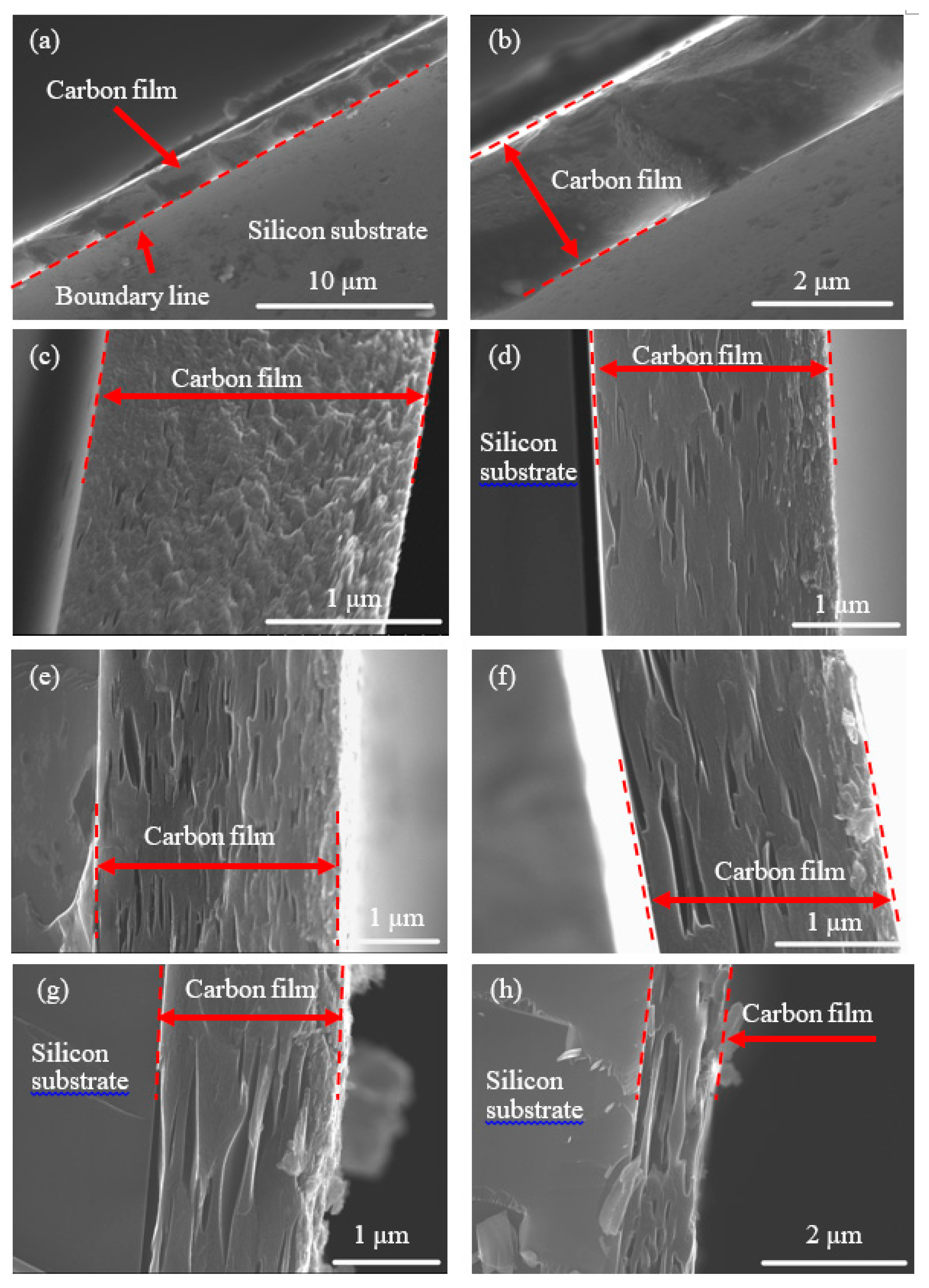
3.2. Fabrication and Morphology of Carbon Films

The general procedures used here to fabricate the solid/porous carbon films were reported in detail in our preceding publication [45]. Before the fabrication, TGA measurements were conducted to determine the behavior of the polymers during the PAN stabilization (at 230 °C for 6 h) and the carbonization process conducted by heating the material to 1000 °C. PAN’s stabilization is necessary to prepare the PAN-based material for further high-temperature carbonization [22,45]. The results are shown in Figure 4. It was observed that during the stabilization process, PET and PAN had 3 wt.% and 7 wt.% mass loss, respectively. Thus, no significant thermal degradation of PET occurred during the stabilization process. We associate the mass loss with water absorbed by the polymer. The mass loss of PAN (beside absorbed water) was mainly caused by the chemical reactions of macromolecular cyclization to form a ladder-type polymer in addition to the dehydrogenation and oxidation [22]. During the initial phase of carbonization (230–600 °C), significant thermal degradation of PET was observed. Specifically, the major mass change of the material (>80 wt.%) takes place between 370–500 °C, and the mass of PET residue was around 12 wt.% at the end of the first phase of carbonization. In this initial carbonization stage, PAN lost about 25 wt.% of its mass. During the next step of carbonization (600–1000 °C), PET lost ~2 wt.% of its original mass. Simultaneously, the mass of PAN residue decreased from 68 wt.% to 52 wt.%. In the course of the final annealing at 1000 °C, PET lost an additional 4 wt.%, and, therefore, the carbon residue of the polymer is ~6 wt.%. PAN lost approximately 6 wt.% during the final annealing leaving the carbon residue of about 46 wt.%.
The temperature profile used in the TGA analysis Figure 4 was employed for the fabrication of carbon films. First, the polymer films after air drying were stabilized under air at 230 °C for 6 h. After the stabilization, the film thickness decreased in the range of 10–25% for PAN and PAN/PET films (Figure 3). Only for the film with a 75/25 PAN/PET ratio, there was no measurable change of thickness. The reason for this was not clear at the time of this writing. The color of stabilized polymer films was dark brown. After carbonization, the films became black. The carbon film thickness was measured using AFM (Figure 3). The thickness decreased significantly in comparison to that of stabilized films. The thickness of solid carbon film made from PAN (at withdrawal speed of 25 mm/min) is around 0.61 μm, which is a 75% decrease from that of the initial polymer film. The reduction of thickness for the carbon films obtained for PAN/PET mixtures was about 40–60%. The porous carbon films with the PET percentages of 10, 20, 25, 30, 35, and 40 had thicknesses of 0.65, 0.39, 0.55, 0.46, 0.57, and 0.38 μm, respectively. The thicknesses of carbon films obtained from polymer films dip-coated at the withdrawal speed of 250 mm/min were also measured using AFM Figure 3. The solid carbon film was 1.65 μm. The porous carbon film thicknesses were on the similar level 1.83, 1.75, 1.27, 1.46, 1.38, and 0.82 μm for 10, 20, 25, 30, 35, and 40% PET in the PAN/PET mixtures, respectively. We did not find a significant correlation between the composition of the PAN/PET mixture and the thickness of the carbon films obtained. However, there is a clear dependence of the thickness on the withdrawal speed used during the polymer film fabrication. Thus, the speed can be used to fabricate the porous carbon film of different thicknesses.
The morphology of carbon films was observed with AFM. The images of the porous films generated from polymer films dip-coated at the withdrawal speed of 25 mm/min are shown in Figure 5. Continuous porous carbon structures were observed, which indicated that a continuous PAN structure was formed during polymer film formation from the binary PAN/PET solutions. The continuous network of the porous PAN structure survived the stabilization and carbonization process without forming cracks. The same observation was made for the films obtained using the higher withdrawal speed (images are not shown). The correlation between PET content and pore size and the one between the withdrawal speed and pore size are maintained through the carbonization process (Figure 2). As the percentage of PET and withdrawal speed increases, the pore size in the carbon films increases. For the carbon films generated from polymer films dip-coated at 25 mm/min, the pore diameters are 0.11, 0.19, 0.32, 0.70, 2.67, and 3.16 μm as the PET percentage in the original polymer films increased from 10, 20, 25, 30, 35, to 40. When the polymer films were formed at the dip-coating withdrawal speed of 250 mm/min, the corresponding pore diameters were 0.11, 0.23, 0.40, 0.72, 3.81, and 10.16 μm. The carbon structure’s pore sizes were also larger than the corresponding pore sizes in the polymer films Figure 2. The mass loss of PAN and PET contributed to the larger pore size in the carbon structure. In general, we determined that the PET content and withdrawal speed could be employed to vary the diameter of pores in the carbon films.
AFM provided accurate information only on the topmost morphology of the films. To complement AFM imaging, the cross-section of carbon films, fabricated from PAN and PAN/PET, were examined using SEM (Figure 6). Figure 6a,b show that the films made from pure PAN do not have a porous structure. Figure 6c–h display the cross-section of the films obtained from the PAN/PET mixture. These films have a significant number of pores in their structure. The pores were found to be elliptical in shape because of the film shrinkage in the vertical direction during stabilization and carbonization processes. The shrinkage in the horizontal direction was constrained by the bonding of the film to the substrates. The film’s thickness and the pores’ size were dependent on PET content. At the PET concentration of 10 wt.%, the carbon films obtained have the internal pore of the smallest size (Figure 6c) that appear not to be interconnected. As the concentration of PET in the polymer film increased, the pores formed in the carbon films became larger, and the number of interconnected pores increased (Figure 6d–h). At the PET concentration of 40% (Figure 6h), the carbon film included a significant fraction of pores in the structure. It is necessary to note that the thickness of the carbon films measured with AFM and the one estimated from SEM were within 10–20% of each other.

3.3. Interlaminar Shear Testing

We hypothesized that porous carbon structure will demonstrate higher adhesion to thermoplastic PP in comparison with non-porous carbon substrate. To test this, we evaluated the effect of the porous coating on interfacial bonding strength between PP and graphite plates. To this end, the porous carbon films were fabricated on the surfaces of the plates using a PAN/PET ratio of 65/35 and withdrawal speed of 250 mm/min. PP grafted with 1 wt.% of maleic anhydride was used in the adhesion test, since it was previously reported that maleic anhydride units improve carbon-PP adhesion [26,28,30]. The schematic of the single lap-joint specimen used in our measurements is shown in Figure 7a. The solid carbon film fabricated from pure PAN film was also deposited on the graphite plates to be used as the control samples. The shear strength results calculated from the tests are shown in Figure 7b. The graphite plates coated with the porous carbon film had a significantly higher shear strength (~8.2 MPa) than those coated with the solid carbon film (~4.9 MPa). Therefore, the modification of carbon materials with the porous surface structure developed in this study improved the interfacial shear strength by ~70%.
The morphology of the fractured interface was observed with SEM (Figure 7c–h). The adhesive failure for the graphite plates coated with the solid carbon film occurred at the polymer/carbon interface (Figure 7c–e). For the plates coated with the porous carbon films, penetration/infiltration of polymer into the pores can be identified from the fracture interface (Figure 7f–h), which also shows the predominantly cohesive failure of the PP matrix. In this failure mode, the interfacial stress causes shear deformation and polymer matrix breakage, indicating that the carbon/PP interfacial bonding is significantly enhanced. The increase of the inter-laminar shear strength is also associated with the increased contact area for the porous structure due to polymer penetration into the internal pores. Indeed, the polymer matrix penetrated in the surface (Figure 7f) and internal pores (Figure 7g,h), and interlocking interphase between PP and the porous carbon structure was formed. The polymer that penetrated the internal pores was stretched during the failure. This conclusion is supported by the extensive fibrillation of the polymer phase (Figure 7f–h). We also note that the carbon porous coating was not damaged during the mechanical test, indicating a strong porous carbon structure was formed using the technique reported here.

4. Conclusions

We demonstrated that porous carbon films with controllable thickness and surface/internal structures could be fabricated by the carbonization of PAN/PET films made through a dip-coating process. PET functioned as a pore former in the polymer film. After carbonization of the polymer, porous carbon films with thicknesses from 0.38–1.83 μm and pore diameters between 0.1–10 μm were obtained. The higher concentrations of PET in the PAN/PET mixture and the higher withdrawal speed during dip-coating caused the formation of larger pores. The thickness of the carbon films can be controlled by the withdrawal speed during dip-coating. We determined that deposition of the porous carbon film on graphite substrate significantly increases the value of the interfacial shear strength between graphite plates and thermoplastic PP. This study has shown the feasibility of fabrication of 3D porous carbon structure on the surface of carbon materials for increasing the interfacial strength. This approach can be used for the fabrication of high-performance carbon fiber-thermoplastic composites.

Author Contributions

Investigation, Y.P., R.B. (Ruslan Burtovyy), R.B. (Rajendra Bordia) and I.L.; Writing—original draft, Y.P. and I.L.; Writing—review & editing, Y.P., R.B. (Rajendra Bordia) and I.L. All authors have read and agreed to the published version of the manuscript.

Funding

This work was supported, in part, by the National Science Foundation EPSCoR Program under NSF Award # OIA-1655740.

Acknowledgments

Any opinions, findings, and conclusions, or recommendations expressed in this material are those of the author(s) and do not necessarily reflect those of the National Science Foundation. Y.P. also acknowledges a postdoctoral research fellowship funded by Clemson University.

Conflicts of Interest

The authors declare no conflict of interest

References

  1. Bledzki, A.K.; Seidlitz, H.; Krenz, J.; Goracy, K.; Urbaniak, M.; Rosch, J.J. Recycling of Carbon Fiber Reinforced Composite Polymers-Review-Part 2: Recovery and Application of Recycled Carbon Fibers. Polymers 2020, 12, 3003. [Google Scholar] [CrossRef] [PubMed]
  2. Deng, J.Y.; Xu, L.; Liu, J.H.; Peng, J.H.; Han, Z.H.; Shen, Z.G.; Guo, S.H. Efficient Method of Recycling Carbon Fiber from the Waste of Carbon Fiber Reinforced Polymer Composites. Polym. Degrad. Stabil. 2020, 182. [Google Scholar] [CrossRef]
  3. Gopalraj, S.K.; Karki, T. A Review on the Recycling of Waste Carbon Fibre/Glass Fibre-Reinforced Composites: Fibre Recovery, Properties and Life-Cycle Analysis. Sn. Appl. Sci. 2020, 2, s42452-s020. [Google Scholar]
  4. Kiss, P.; Stadlbauer, W.; Burgstaller, C.; Stadler, H.; Fehringer, S.; Haeuserer, F.; Archodoulaki, V.M. In-House Recycling of Carbon- and Glass Fibre-Reinforced Thermoplastic Composite Laminate Waste into High-Performance Sheet Materials. Compos. Part A Appl. Sci. Manuf. 2020, 139. [Google Scholar] [CrossRef]
  5. Kumar, S.; Krishnan, S. Recycling of Carbon Fiber with Epoxy Composites by Chemical Recycling for Future Perspective: A Review. Chem. Pap. 2020, 74, 3785–3807. [Google Scholar] [CrossRef]
  6. Utekar, S.; Suriya, V.K.; More, N.; Rao, A. Comprehensive Study of Recycling of Thermosetting Polymer Composites - Driving Force, Challenges and Methods. Compos. Part B Eng. 2021, 207. [Google Scholar] [CrossRef]
  7. Zhang, J.; Chevali, V.S.; Wang, H.; Wang, C.H. Current Status of Carbon Fibre and Carbon Fibre Composites Recycling. Compos. Part. B Eng. 2020, 193. [Google Scholar] [CrossRef]
  8. Pimenta, S.; Pinho, S.T. Recycling Carbon Fibre Reinforced Polymers for Structural Applications: Technology Review and Market Outlook. Waste Manag. 2011, 31, 378–392. [Google Scholar] [CrossRef] [Green Version]
  9. Li, P.D.; Zhao, Y.; Long, X.; Zhou, Y.W.; Chen, Z.Y. Ductility Evaluation of Damaged Recycled Aggregate Concrete Columns Repaired With Carbon Fiber-Reinforced Polymer and Large Rupture Strain FRP. Front. Mater. 2020, 7. [Google Scholar] [CrossRef]
  10. Tapper, R.J.; Longana, M.L.; Norton, A.; Potter, K.D.; Hamerton, I. An Evaluation of Life Cycle Assessment and its Application to the Closed-Loop Recycling of Carbon Fibre Reinforced Polymers. Compos. Part. B Eng. 2020, 184. [Google Scholar] [CrossRef]
  11. Giorgini, L.; Benelli, T.; Brancolini, G.; Mazzocchetti, L. Recycling of Carbon Fiber Reinforced Composite Waste to Close Their Life Cycle in a Cradle-to-Cradle Approach. Curr. Opin. Green Sust. 2020, 26. [Google Scholar] [CrossRef]
  12. Liu, Z.; Turner, T.A.; Wong, K.H.; Pickering, S.J. Development of High Performance Recycled Carbon Fibre Composites with an Advanced Hydrodynamic Fibre Alignment Process. J. Clean Prod. 2021, 278. [Google Scholar] [CrossRef]
  13. Wellekotter, J.; Resch, J.; Baz, S.; Gresser, G.T.; Bonten, C. Insights into the Processing of Recycled Carbon Fibers via Injection Molding Compounding. J. Compos. Sci. 2020, 4, 161. [Google Scholar] [CrossRef]
  14. Ota, H.; Jespersen, K.M.; Saito, K.; Wada, K.; Okamoto, K.; Hosoi, A.; Kawada, H. Effect of the interfacial nanostructure on the Interlaminar Fracture Toughness and Damage Mechanisms of Directly Bonded Carbon Fiber Reinforced Thermoplastics and Aluminum. Compos. Part A Appl. Sci. Manuf. 2020, 139. [Google Scholar] [CrossRef]
  15. Khurshid, M.F.; Hengstermann, M.; Hasan, M.M.B.; Abdkader, A.; Cherif, C. Recent Developments in the Processing of Waste Carbon Fibre for Thermoplastic Composites—A Review. J. Compos. Mater. 2020, 54, 1925–1944. [Google Scholar] [CrossRef]
  16. Roux, M.; Eguemann, N.; Dransfeld, C.; Thiebaud, F.; Perreux, D. Thermoplastic Carbon Fibre-Reinforced Polymer Recycling with Electrodynamical Fragmentation: From Cradle to Cradle. J. Compos. 2017, 30, 381–403. [Google Scholar] [CrossRef]
  17. Hirayama, D.; Saron, C.; Botelho, E.C.; Costa, M.L.; Ancelotti, A.C. Polypropylene Composites Manufactured from Recycled Carbon Fibers from Aeronautic Materials Waste. Mater. Res.-Ibero-Am. J. 2017, 20, 519–525. [Google Scholar] [CrossRef] [Green Version]
  18. Friedrich, K. Carbon Fiber Reinforced Thermoplastic Composites for Future Automotive Applications. AIP Conf. Proc. 2016, 1736. [Google Scholar] [CrossRef]
  19. Stoeffler, K.; Andjelic, S.; Legros, N.; Roberge, J.; Schougaard, S.B. Polyphenylene Sulfide (PPS) Composites Reinforced with Recycled Carbon Fiber. Compos. Sci. Technol. 2013, 84, 65–71. [Google Scholar] [CrossRef]
  20. Sharma, M.; Gao, S.L.; Mader, E.; Sharma, H.; Wei, L.Y.; Bijwe, J. Carbon Fiber Surfaces and Composite Interphases. Compos. Sci. Technol. 2014, 102, 35–50. [Google Scholar] [CrossRef]
  21. Huang, X.S. Fabrication and Properties of Carbon Fibers. Materials 2009, 2, 2369–2403. [Google Scholar] [CrossRef]
  22. Donnet, J.-B.; Wang, T.K.; Peng, J.C.M.; Rebouillat, S. Carbon Fibers, 3rd ed.; Marcel Dekker Inc.: New York, NY, USA, 1998. [Google Scholar]
  23. Fu, S.Y.; Lauke, B.; Mäder, E.; Yue, C.Y.; Hu, X. Tensile Properties of Short-Glass-Fiber- and Short-Carbon-Fiber-Reinforced Polypropylene Composites. Compos. Part A Appl. Sci. Manuf. 2000, 31, 1117–1125. [Google Scholar] [CrossRef]
  24. Gamze Karsli, N.; Aytac, A.; Akbulut, M.; Deniz, V.; Güven, O. Effects of Irradiated Polypropylene Compatibilizer on the Properties of Short Carbon Fiber Reinforced Polypropylene Composites. Radiat. Phys. Chem. 2013, 84, 74–78. [Google Scholar] [CrossRef]
  25. Han, S.H.; Oh, H.J.; Kim, S.S. Evaluation of Fiber Surface Treatment on the Interfacial Behavior of Carbon Fiber-Reinforced Polypropylene Composites. Compos. Part. B Eng. 2014, 60, 98–105. [Google Scholar] [CrossRef]
  26. Karsli, N.G.; Aytac, A. Effects of Maleated Polypropylene on the Morphology, Thermal and Mechanical Properties of Short Carbon Fiber Reinforced Polypropylene Composites. Mater. Des. 2011, 32, 4069–4073. [Google Scholar] [CrossRef]
  27. Rezaei, F.; Yunus, R.; Ibrahim, N.A. Effect of Fiber Length on Thermomechanical Properties of Short Carbon Fiber Reinforced Polypropylene Composites. Mater. Des. 2009, 30, 260–263. [Google Scholar] [CrossRef]
  28. Tian, H.; Yao, Y.; Liu, D.; Li, Y.; Jv, R.; Xiang, G.; Xiang, A. Enhanced Interfacial Adhesion and Properties of Polypropylene/Carbon Fiber Composites by Fiber Surface Oxidation in Presence of a Compatibilizer. Polym. Compos. 2019, 40, E654–E662. [Google Scholar] [CrossRef]
  29. Tian, H.F.; Yao, Y.Y.; Wang, C.Y.; Jv, R.; Ge, X.; Xiang, A.M. Essential Work of Fracture Analysis for Surface Modified Carbon Fiber/Polypropylene Composites with Different Interfacial Adhesion. Polym. Compos. 2020, 41, 3541. [Google Scholar] [CrossRef]
  30. Unterweger, C.; Duchoslav, J.; Stifter, D.; Fürst, C. Characterization of Carbon Fiber Surfaces and Their Impact on the Mechanical Properties of Short Carbon Fiber Reinforced Polypropylene Composites. Compos. Sci. Technol. 2015, 108, 41–47. [Google Scholar] [CrossRef]
  31. Vishkaei, M.S.; Salleh, M.A.M.; Yunus, R.; Biak, D.R.A.; Danafar, F.; Mirjalili, F. Effect of Short Carbon Fiber Surface Treatment on Composite Properties. J. Compos. Mater. 2010, 45, 1885–1891. [Google Scholar] [CrossRef]
  32. Zhang, K.; Li, Y.; He, X.; Nie, M.; Wang, Q. Mechanical Interlock Effect Between Polypropylene/Carbon Fiber Composite Generated by Interfacial Branched Fibers. Compos. Sci. Technol. 2018, 167, 1–6. [Google Scholar] [CrossRef]
  33. Huang, Y.L.; Young, R.J. Interfacial Micromechanics in Thermoplastic and Thermosetting Matrix Carbon Fibre Composites. Compos. Part A Appl. Sci. Manuf. 1996, 27, 973–980. [Google Scholar] [CrossRef]
  34. Tang, L.G.; Kardos, J.L. A Review of Methods for Improving the Interfacial Adhesion between Carbon Fiber and Polymer Matrix. Polym. Compos. 1997, 18, 100–113. [Google Scholar] [CrossRef]
  35. Gravis, D.; Moisan, S.; Poncin-Epaillard, F. Characterization of surface physico-chemistry and morphology of plasma-sized carbon fiber. Thin Solid Films 2021, 721, 11. [Google Scholar] [CrossRef]
  36. Donnet, J.B.; Brendle, M.; Dhami, T.L.; Bahl, O.P. Plasma Treatment Effect on the Surface-Energy of Carbon and Carbon-Fibers. Carbon 1986, 24, 757–770. [Google Scholar] [CrossRef]
  37. Donnet, J.B.; Cazeneuve, C.; Schultz, J.; Shanahan, M.E.R. Surface-Energy of Carbon-Fibers. Carbon 1980, 18, 61. [Google Scholar]
  38. Donnet, J.B.; Dhami, T.L.; Dong, S.; Brendle, M. Microwave Plasma Treatment Effect on the Surface-Energy of Carbon-Fibers. J. Phys. D Appl. Phys. 1987, 20, 269–275. [Google Scholar] [CrossRef]
  39. Donnet, J.B.; Ehrburger, P. Carbon-Fiber in Polymer Reinforcement. Carbon 1977, 15, 143–152. [Google Scholar] [CrossRef]
  40. Donnet, J.B.; Guilpain, G. Surface Treatments and Properties of Carbon-Fibers. Carbon 1989, 27, 749–757. [Google Scholar] [CrossRef]
  41. Donnet, J.B.; Guilpain, G. Surface Characterization of Carbon-Fibers. Composites 1991, 22, 59–62. [Google Scholar] [CrossRef]
  42. Ehrburger, P.; Herque, J.J.; Donnet, J.P. Recent Developments in Carbon-Fiber Treatments. Acs. Sym. Ser. 1976, 324–334. [Google Scholar]
  43. Sadeghvishakei, M.; Yunus, R.; Salleh, M.A.M.; Pignolet, A. Mechanical Investigation in Whiskerized Carbon Fiber/Polypropylene Composite. In Proceedings of the Smart Materials, Structures & NDTin Aerospace, Montreal, QC Canada, November 2011. [Google Scholar]
  44. Zhang, Q.H.; Liu, J.W.; Sager, R.; Dai, L.M.; Baur, J. Hierarchical Composites of Carbon Nanotubes on Carbon Fiber: Influence of Growth Condition on Fiber Tensile Properties. Compos. Sci. Technol. 2009, 69, 594–601. [Google Scholar] [CrossRef]
  45. Peng, Y.C.; Burtovyy, R.; Yang, Y.; Urban, M.W.; Kennedy, M.S.; Kornev, K.G.; Bordia, R.; Luzinov, I. Towards scalable Fabrication of Ultrasmooth and Porous thin Carbon Films. Carbon 2016, 96, 184–195. [Google Scholar] [CrossRef]
  46. Fried, J. Polymer Science and Technology, 3rd ed.; Pearson: London, UK, 2014. [Google Scholar]
  47. Seeber, M.; Zdyrko, B.; Burtovvy, R.; Andrukh, T.; Tsai, C.-C.; Owens, J.R.; Kornev, K.G.; Luzinov, I. Surface Grafting of Thermoresponsive Microgel Nanoparticles. Soft Matter. 2011, 7, 9962–9971. [Google Scholar] [CrossRef]
  48. Walheim, S.; Böltau, M.; Mlynek, J.; Krausch, G.; Steiner, U. Structure Formation via Polymer Demixing in Spin-Cast Films. Macromolecules 1997, 30, 4995–5003. [Google Scholar] [CrossRef]
  49. Elbs, H.; Fukunaga, K.; Stadler, R.; Sauer, G.; Magerle, R.; Krausch, G. Microdomain Morphology of Thin ABC Triblock Copolymer Films. Macromolecules 1999, 32, 1204–1211. [Google Scholar] [CrossRef]
  50. Landau, L.; Levich, B. Dragging of a Liquid by a Moving Plate. Acta. Phys. URSS 1942, 17, 42–54. [Google Scholar]
  51. Mayer, H.C.; Krechetnikov, R. Landau-Levich Flow Visualization: Revealing the Flow Topology Responsible for the Film Thickening Phenomena. Phys. Fluids 2012, 24. [Google Scholar] [CrossRef] [Green Version]
Figure 1. AFM topographical images of polymer films as deposited on silicon wafer by dip-coating: (a) PAN/PET-10-25, (b) PAN/PET-20-25, (c) PAN/PET-25-25, (d) PAN/PET-30-25, (e) PAN/PET-35-25, and (f) PAN/PET-40-25. The scale bar on the right side of the AFM images depicts the height scale of the image, where light and dark shades correspond to high and low relative heights, respectively.
Jcs 05 00108 g001
Figure 2. Pore diameters for porous polymer (a) and carbon (b) films obtained from AFM images.
Jcs 05 00108 g002
Figure 3. The thicknesses of the deposited polymer films, stabilized films, and carbon films.
Jcs 05 00108 g003
Figure 4. Temperature profile for the stabilization and carbonization processes used and corresponding TGA traces for pure PAN and PET.
Jcs 05 00108 g004
Figure 5. AFM topographical images of the carbonized polymer films obtained from (a) PAN/PET-10-25, (b) PAN/PET-20-25, (c) PAN/PET-25-25, (d) PAN/PET-30-25, (e) PAN/PET-35-25, and (f) PAN/PET-40-25. The scale bar on the right side of the AFM images depicts the height scale of the image, where light and dark shades correspond to high and low relative heights, respectively.
Jcs 05 00108 g005
Figure 6. The SEM micrographs showing the cross-section of carbon films prepared from polymer films: (a,b) pure PAN, (c) PAN/PET-10-250, (d) PAN/PET-20-250, (e) PAN/PET-25-250, (f) PAN/PET-30-250, (g) PAN/PET-35-250, and (h) PAN/PET-40-250.
Jcs 05 00108 g006
Figure 7. The schematic of the single lap-joint specimen (a), the shear strength results (b), and the SEM micrographs showing the fracture surfaces of solid (ce) and porous (fh) carbon-coated graphite plates.
Jcs 05 00108 g007
Table 1. Sample nomenclature.
Sample NamePolymer Concentration
in Solution (wt.%)
PAN/PET
(by Weight)
Dip-Coating
Withdrawal Speed
(mm/min)
PAN-3-253100/025
PAN-3-2503100/0250
PAN/PET-10-25390/1025
PAN/PET-20-25380/2025
PAN/PET-25-25375/2525
PAN/PET-30-25370/3025
PAN/PET-35-25365/3525
PAN/PET-40-25360/4025
PAN/PET-10-250390/10250
PAN/PET-20-250380/20250
PAN/PET-25-250375/25250
PAN/PET-30-250370/30250
PAN/PET-35-250365/35250
PAN/PET-40-250360/40250
Publisher’s Note: MDPI stays neutral with regard to jurisdictional claims in published maps and institutional affiliations.

