Article

Mechanical and FEA-Assisted Characterization of Fused Filament Fabricated Triply Periodic Minimal Surface Structures

by
Nikolaos Kladovasilakis
,
Konstantinos Tsongas
and
Dimitrios Tzetzis
*
Digital Manufacturing and Materials Characterization Laboratory, School of Science and Technology, International Hellenic University, 57001 Thessaloniki, Greece
*
Author to whom correspondence should be addressed.
J. Compos. Sci. 2021, 5(2), 58; https://doi.org/10.3390/jcs5020058
Submission received: 19 January 2021 / Revised: 10 February 2021 / Accepted: 11 February 2021 / Published: 17 February 2021
(This article belongs to the Special Issue Feature Papers in Journal of Composites Science in 2021)

Abstract

:
This paper investigates the mechanical behavior of additive manufactured Triply Periodic Minimal Surface (TPMS) structures, such as Gyroid, Schwarz Diamond and Schwarz Primitive. Fused Filament Fabrication (FFF) technique was utilized in order to fabricate lattice structures with different relative densities, at 10%, 20% and 30%, using Polylactic acid (PLA). The test specimens were formed by structural TPMS unit cells and they were tested under quasi-static compression. A finite element analysis (FEA) was performed in order to predict their stress-strain behavior and compare with the experimental results. The results revealed that each architecture influences the mechanical properties of the structure differently depending on the impact of size effect. The structures were designed as sandwich structures (with a top and bottom plate) to avoid significant deterioration of the mechanical behavior, due to the size effect and this was achieved at high relative densities. The Schwarz Diamond structure demonstrated the highest mechanical strength compared with the other architectures, while the Gyroid structure also revealed a similar mechanical performance. In addition, Schwarz Primitive structure showed increased energy absorption especially during plastic deformation. The overall results revealed that the integrity of the mechanical properties of the studied TPMS FFF printed structures deteriorates, as the relative density of the structures decreases.

1. Introduction

Nowadays, owing to the involvement of additive manufacturing (3D Printing) techniques, topology optimization through lattice designs, has been studied experimentally and it could be applied in various industries; indicatively in aerospace, automotive, biomechanical engineering and so forth [1,2]. There is a plethora of lattice structures either naturally formed (foams, bones etc.) or artificially formed, through 3D printing and other manufacturing techniques. Artificially formed lattice structures provide unique properties to the structure, such as high amount of energy absorption, high porosity and high surface area to volume ratio which offer comprehensive advantages for application like packaging, thermal and acoustic isolation, biomechanical and mechanical applications [3,4]. Specifically, according to the review article of Mahmoud and Elbestawi [5], there are studies with 3D printed medical implants, which demonstrate similar porosity to the human bones due to their cellular structure, in order to facilitate cells, blood and nutrients diffusion for tissue regeneration purposes [6,7]. Besides, bone implant applications and in accordance with the review of Henríquez et al. [4], additive manufactured polymer structures, could be utilized in another medical application, such as scaffolds [8,9] or as stent implants [10,11]. In addition, Tao and Leu [12] have utilized topology optimization through lattice structures, with the aim of manufacturing lightweight mechanical components. Even more, the use of lattice geometries results in high surface area-to-volume ratio structures, suitable for applications such as catalysts [13] and heat exchanges [14].
However, it is evident from the existing literature [3,15] that the lattice structures affect the mechanical response of a whole structure. According to Simone and Gibson [15], the decrease in the mechanical properties of lattice structures occurs due to the size effect. The size effect is mainly influenced by the relative density (foam structure) and the geometric parameters of each lattice structure. In particular, the mechanical properties of a structure, such as elastic modulus and yield strength, appear to be different from a solid material, which is the reason why an effective elastic modulus is usually calculated. The majority of the literature on this topic has focused on geometries consisting of strut structures. These studies have shown that elastic modulus is affected as follows Elattice/Esolid = Cnrelative) n and yield strength as follows: σlatticesolid = Cmrelative) m. The variables Cn, Cm, n and m are variables influenced by geometry, that is, for each lattice structure applied. The variables Cn and Cm range from 0.1 to 4.0, while the variables n and m could vary from 1.0 to 2.0 for stretching-dominated and bending-dominated mechanical behavior, respectively [16]. Increased exponential indices (n and m), may lead to intense size effect phenomena at low relative densities [17,18,19]. The current literature on lattice Triply Periodic Minimal Surface (TPMS) structures shows that the same phenomenon appears on such structures as well. Nevertheless, according to studies of Al-Katen et al. [20] and Li et al. [21], TPMS geometries have smaller exponential coefficients than lattice structures with struts. Indicatively, the behavior of sheet-TPMS structures is closer to stretching-dominated behavior, which means that n and m could be close to the value one; hence, the size effect on these structures is significantly smaller [22,23,24]. Thereby, the values of all mechanical properties and especially the elastic modulus and yield strength were reduced for lattice structures due to the size effect. This decrease, in proportion to the relative density, causes a significant reduction in mechanical properties values up to 70–80% for relative densities of less than 15% [3].
It is widely known that the mechanical properties of 3D printed parts differ as compared to the mechanical properties of parts manufactured with traditional fabrication methods, such as injection molding in the case of thermoplastics [25]. The reduction of mechanical properties is mainly due to the 3D printing technique (Fused Filament Fabrication-FFF, Selective Laser Sintering-SLS, etc.), the build orientation and the printing parameters (print speed, layer thickness, etc.) [26]. There is a plethora of studies that demonstrate the changes in mechanical properties especially in relation with the 3D printing parameters [27,28,29]. When the part contains lattice structures, the reduction of the mechanical properties is even greater. Therefore, it is important to propose a design that avoids compromising the mechanical performance and investing the response of such FFF printed structures.
Based on the above, the current research is focused on lattice structures, which consist of TPMS elements, such as Gyroid, Schwarz Diamond and Schwarz Primitive. The examined mechanical properties of such TPMS structures are the stiffness, the effective elasticity modulus and the yield strength, with respect to the relative density and changing architecture. The aim was to reduce the impact of the size effect, to identify the compressive yield strength of each geometry and observe fracture modes that could predict the mechanical behavior of each TPMS geometry. More specifically, this study targets to reduce the phenomenon of size effect; in order to achieve that, the TPMS unit cells’ dimensions (length and thickness) should be comparatively large to the whole structure. For that reason, solid plates were also fabricated on the upper and bottom side of the specimens creating novel sandwich-like structures, in order to maintain the structural integrity of the specimens. The innovation of this research focuses on the use of low-cost fuse filament fabrication (FFF) method to study the mechanical behavior of TPMS structures, since the majority of investigations for such structures focus on using more advanced 3D printing technologies and FFF on such structures is not commonly investigated in literature, according to the authors’ knowledge. The 3D printing material used was Polylactic acid or polylactide (PLA), which is low-cost and biocompatible polymer suitable for medical use [30]. Subsequently, mechanical tests were carried out on the 3D printed TPMS structures to examine and compare their performance. The experimental data were curve-fitted with the results of finite element analysis in order to derive predictive patterns of the mechanical behavior of the TPMS architectures at different relative densities.

2. Design and Experimental Methods

2.1. Procedure of Design and 3D Printing of Lattice Structures

Minimal surfaces are surfaces that have the characteristic of an average curvature of zero at every domain’s points. When these minimal surfaces are periodic and develop at three dimensions are called Triply Periodic Minimal Surfaces (TPMS). TPMS are divided into balanced and unbalanced surfaces; in this study balanced TPMS are examined, that are surfaces divided into equal volumes in each unit cell. Nowadays, there is a plethora of tools that could extract the unit cell’s coordinates of each TPMS. The most widespread and reliable technique leading to TPMS-like topologies is through the utility of Fourier transform equations. This method results in a combination of trigonometric equations defined as follows: Φ(x,y,z) = t. Where Φ is the total formula for the minimum surface and t is the level-set constant [31]. According to existing literature [32,33], there are displayed below the precise functions of the TPMS geometries (Gyroid, Schwarz Diamond, Schwarz Primitive) and their unit cell’s structures (Figure 1) which were studied in this paper:
Gyroid
sinx cosy + siny cosz + sinz sinx = t
Schwarz Diamond
sinx siny sinz + sinx cosy cosz + cosx siny cosz + cosx cosy cosz = t
Schwarz Primitive
cosx + cosy + cosz = t
In order to generate the TPMS geometries the SpaceClaim software was used, which is included in the ANSYS™ software platform. This software contains algorithms, which allow the formation of various lattice structures. The design was completed by applying the above equations and setting the variable t = 0, as according to Zheng et al. (2018), for t = 0 the mechanical performance of the TPMS structures is optimal. Thus, specimens with different lattice structures were designed as cubes and with outer dimensions of 50 mm × 50 mm × 50 mm, which contain 64 TPMS unit cells of 12.5 mm each (4 × 4 × 4). Also, solid plates of 2 mm thickness at the top and bottom of the specimens were designed to maintain the specimen’s integrity and to uniformly distribute the applied loads, as illustrated in Figure 2. The thickness of each unit cell was the main variable that affects the relative density; hence in Table 1, the thickness value for each specimen, is presented.
Polylactic acid (PLA) filament of 2.85 mm diameter, named as PrimaTM Easy-Print, was used for FFF (Fused Filament Fabrication) technique by a BCN3D Sigma R17 printer. The open-source Cura software was used to determine the printing parameters as well as the slicing of the specimen’s geometries. For the manufacturing of the TPMS specimens, no support structures were needed since these designs were self-supported during the printing procedure. Table 2 shows the 3D printing parameters for all the TPMS specimens.

2.2. Microstructure Characterization of the FFF Printed TPMS Structures

The microstructure and fracture characteristics of 3D printed TPMS structures were observed using an optical microscope. The Dino-Lite Pro HR AM 7000/AD7000 digital microscope having 5 MP resolution and 220 times of magnification was used, which was placed on a precision controlled adjustable table. The TPMS structures were captured with an optical microscope prior and after compression testing.

2.3. Nanoindentation and Compression Properties of the Base FFF Material

The mechanical properties of the PLA material were calculated using the nanoindentation technique. This procedure is necessary in order to verify the precise mechanical properties of the feedstock PLA material and provide accuracy to the finite element models, before conducting the experiments. The SHIMADZU DUH-211S (Dynamic Ultra Micro Hardness Tester) equipment was used to calculate the elastic modulus. Details of calculations and employed formalisms can be found in previous work [34,35,36,37,38]. For the current work, the force used for the indentation was 20 mN. At least ten measurements, scattered on the surface of the PLA filament, were performed in order to obtain reliable results.

2.4. Compression Testing of FFF Printed TPMS Lattice Structures

The static uniaxial compression loading tests were performed on TPMS specimens with a universal testing machine Testometric-M500-50AT equipped with 50 kN load cell. All the TPMS specimens were pressed between hardened steel compression platens containing a spherical seat to overcome any small misalignment along the load train. Lubrication was applied on the surfaces of both upper and lower platens. The test specimens were placed between the moving head and fixed head of the test machine where the compressive strain in these tests reached up to 60% of the original specimen’s length, which is the point where the densification of the specimens occurs. The strain rate was selected at 5 mm/min compressive strain rate [39]. All experimental data correspond to the average of at least five different measurements.

2.5. Finite Element Analysis Assisted Simulation of the Mechanical Behavior of the FFF TPMS Structures

A finite element model (FEM) has been developed in order to extract the stress-strain behavior of the 3D printed TPMS structures. It should be noted that the Finite Element Analysis (FEA) for these structures focused on the elastic section of stress-strain diagram, that is, elastic modulus and yield strength, while the post-softening behavior was simulated by utilizing Prony series relaxation model. This model is sophisticated enough to provide a good quantitative fit to any polymer over an extended period [40]. That way, the behavior of the PLA material after yielding was assumed to deform viscoelastically. ANSYS™ software was used for the finite element analysis and static structural module was selected to simulate the quasi-static loading. In mechanical solutions from ANSYS, viscoelasticity is implemented through the use of Prony series. The values of shear modulus, μ and bulk modulus, Κ (related to the elastic modulus E and Poisson’s ratio n) are not constant and can be represented by Prony series in viscoelasticity [40]:
μ ( t ) = μ 0 [ 1 i = 1 N μ i e t / τ i μ ]
K ( t ) = K 0 [ 1 i = 1 N K i e t / τ i K ]
where μ0 and Κ0 are the instantaneous shear and bulk moduli and the μi and Ki are the dimensionless shear and bulk relaxation moduli associated with relaxation times τiμ and τiΚ corresponding to deviatoric and volumetric viscosities, respectively. Shear and bulk moduli are represented by a decaying function of time t. Therefore, several pairs of relative moduli μi and relaxation time τi have been provided as input to the FE model, which represented the amount of stiffness lost at a given rate.
The mesh consisted of tetrahedrals for the lattice structures and hexahedrals for the upper and lower plates. In order to ensure the mesh-independent response, a convergence study was performed. Based on the convergence results performed for elastic response of the TPMS structures, an average element size of 0.9 mm was considered to be adequate to obtain acceptable accuracy in the calculated responses. The post-softening was simulated for an adjacent strain region beyond the yield point, approximately up to a strain of 25%. Attempting to simulate the entire deformation region would be rather complicated due to the post-softening process that occurs when crushing these structures [3].

3. Results

3.1. Material Properties and Fabrication of FFF TPMS Specimens

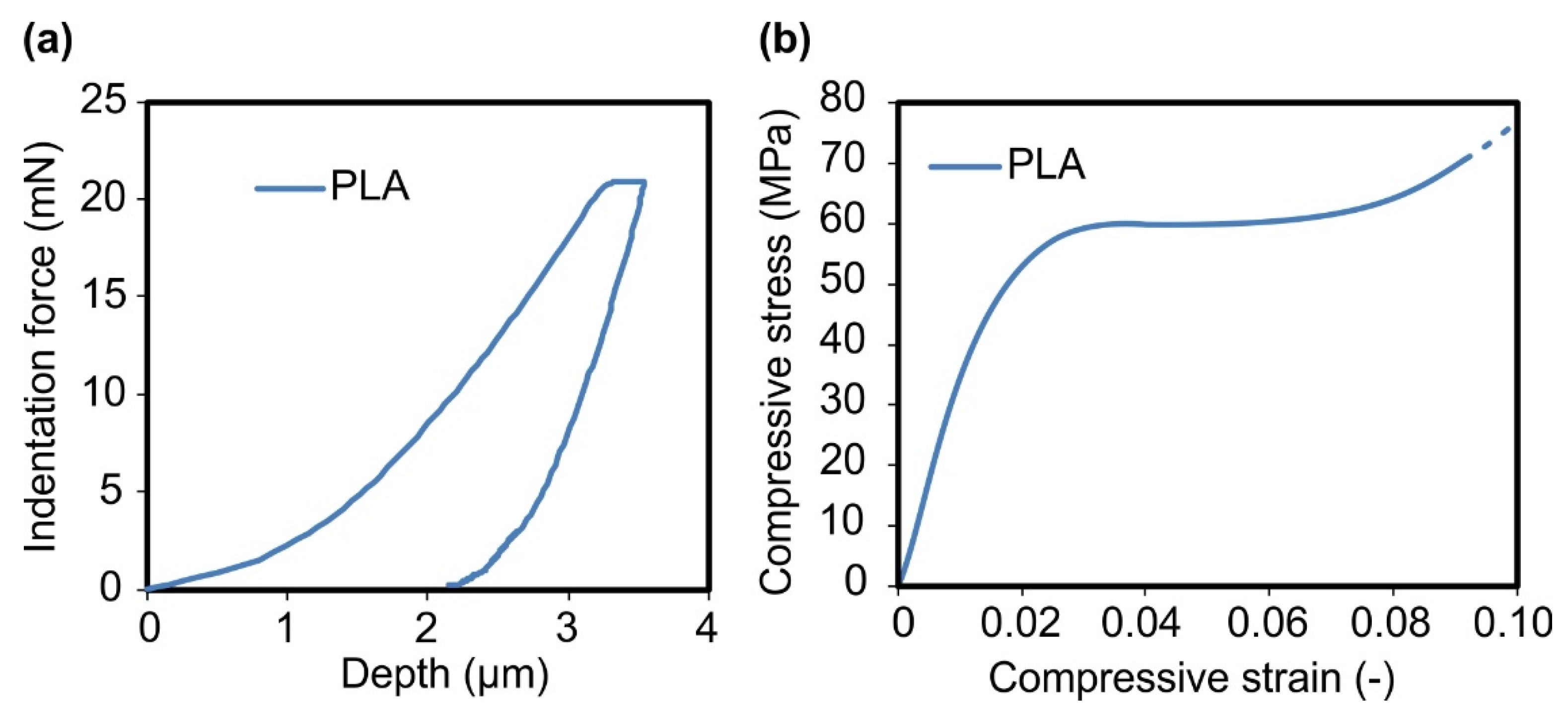
The characterization of the mechanical properties of the filament material used for the fabrication of the specimens is considered essential before conducting the experiments involving the TPMS structures. Figure 3a illustrates the load-depth curves obtained from nanoindentation testing the PLA filament, while Figure 3b portrays a typical stress-strain curve of compression tests of 3D printed PLA cylindrical specimens (with a 29 mm diameter and 12.5 mm height). Following the calculations of the Oliver and Pharr approach [41], the elastic modulus of the PLA filament used in the current work seemed to not diverge compared to values found in the open literature [42]. These values are directly comparable with the results obtained from the compression tests, as shown in Table 3. However, the strain fields in indentation are not uniform, therefore also the strain-rate fields are uniform either; thus, a monotonically direct comparison of rate dependence to compression tests should be assumed with carefulness [43].
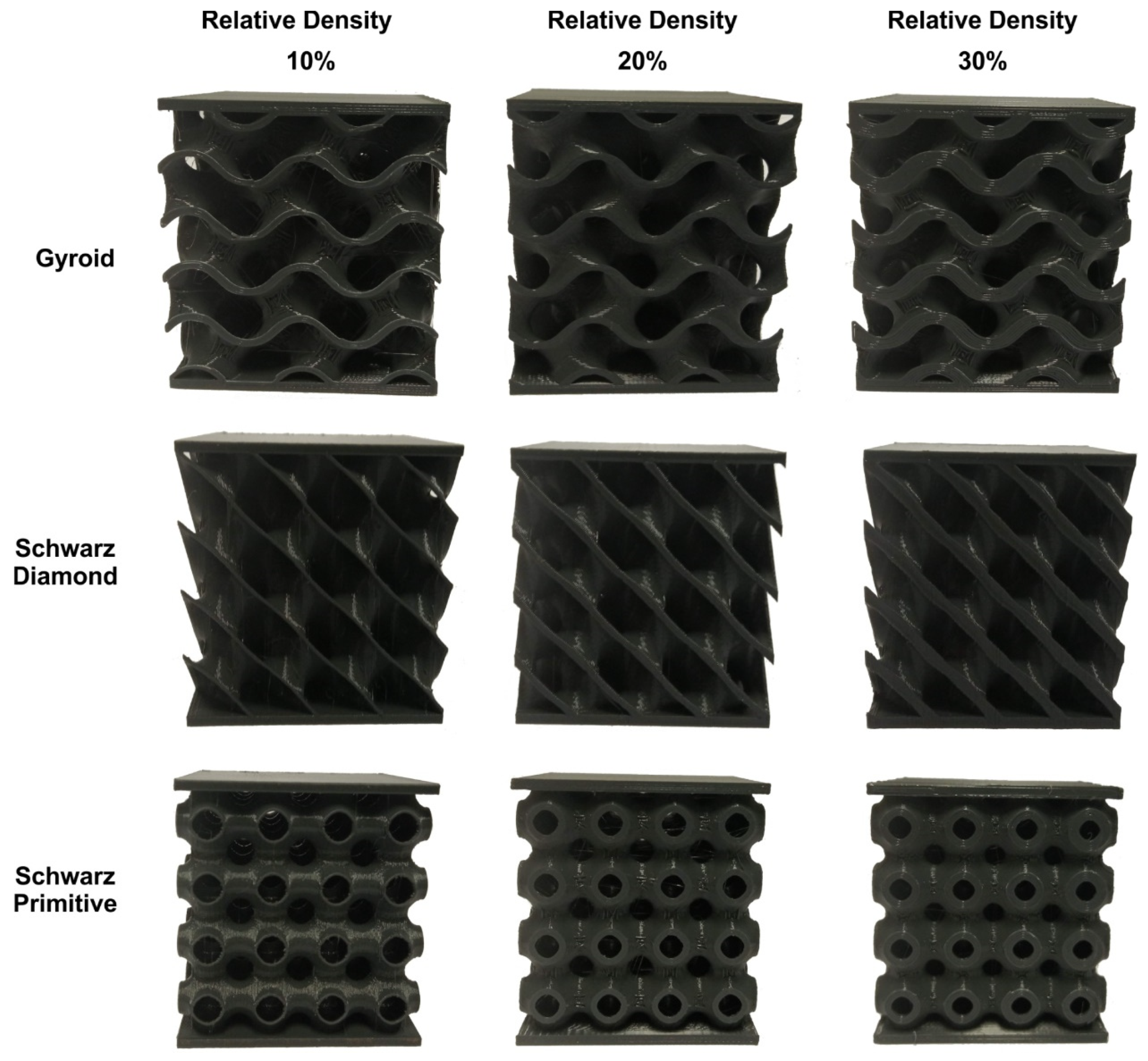
A black colored PLA spool was used to 3D print the TPMS structures. Figure 4 illustrates the 3D printed specimens at the various relative densities, while Table 4 shows the printing time and weight of each specimen. As expected, the higher the relative density, the heavier the specimens are and subsequently more time consuming. The produced specimens appeared to have high dimensional accuracy. Moreover, existing research [34,35] has shown that when the direction of the bonds between the layers is perpendicular to the direction of compressive loads, the maximum compressive strength is achieved. Therefore, for the fabrication of test specimens, the ZXY orientation according to ASTM [44] standard was selected, which also is the optimal print orientation.

3.2. Morphology Characterization of FFF TPMS Structures

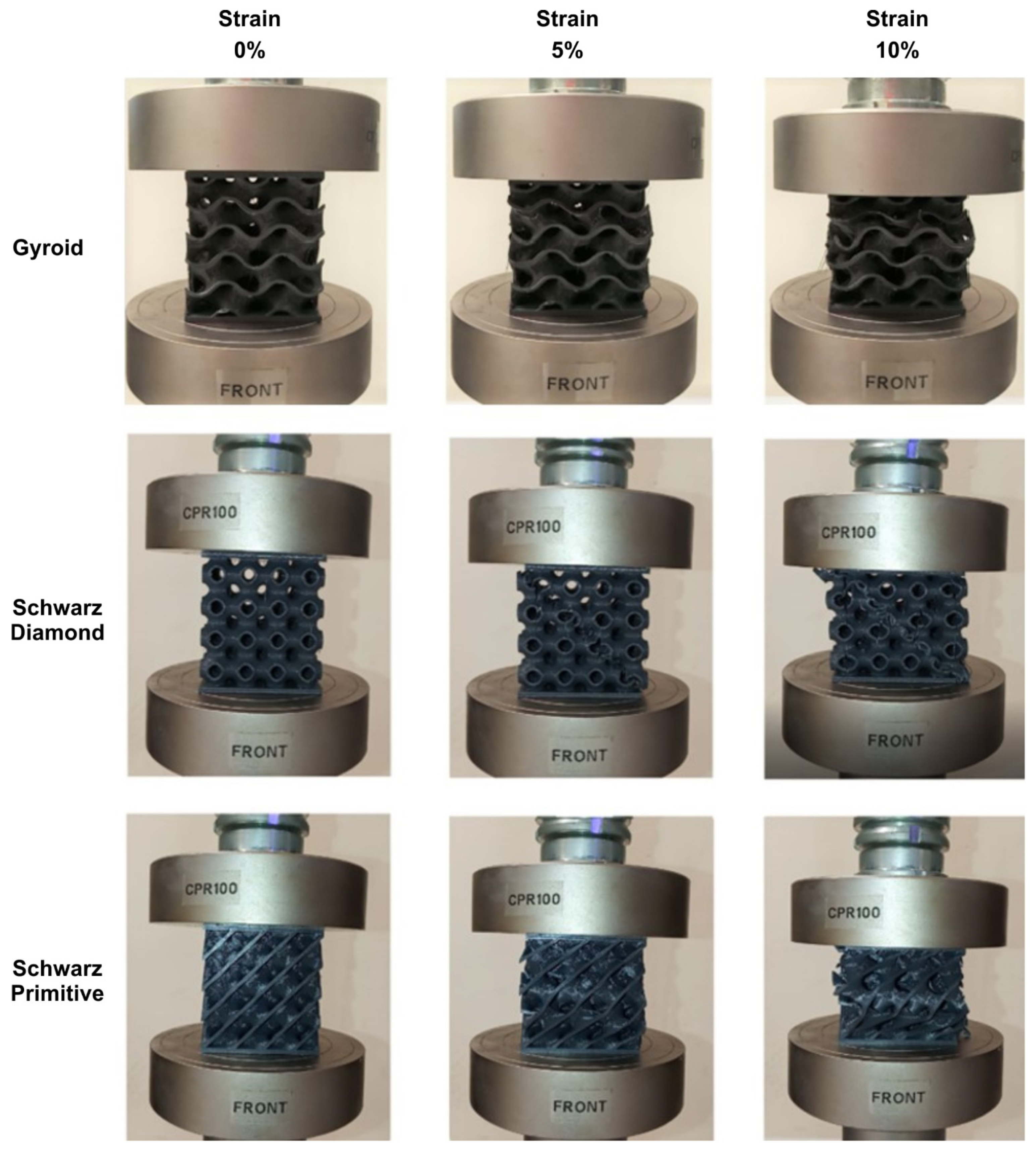
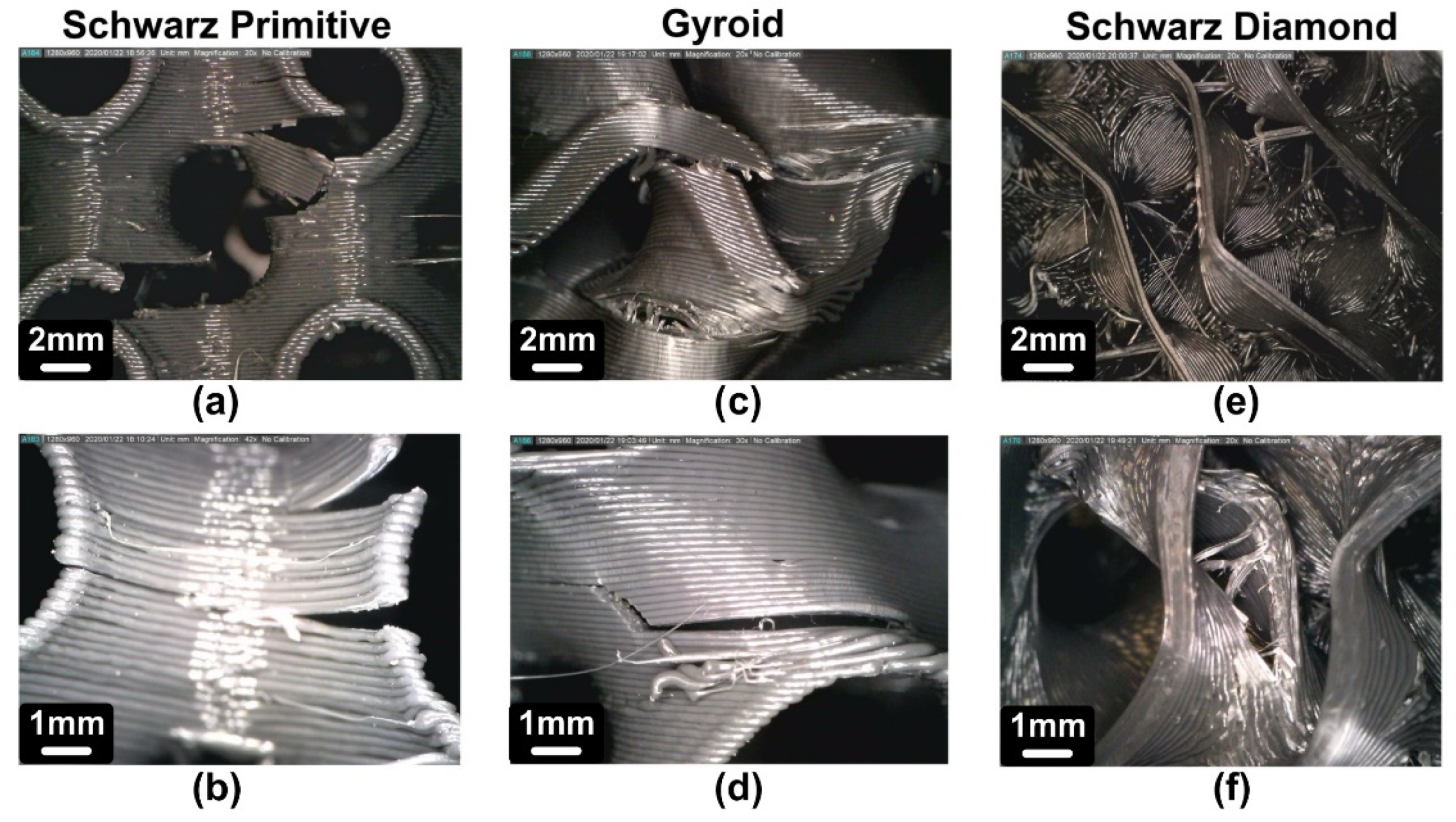
Figure 5 presents the deformation behavior of each TPMS structure under the applied loads. It also shows the condition of each structure for different strains (0%, 5% and 10%). The local microstructure of the TPMS specimens was qualitatively examined at 15% strain using optical microscopy as shown in Figure 6. It portrays the images that were extracted showing characteristic fracture areas of the unit cell of each structure, such as the detachment of layers, the intense shear stresses effect and the stress concentration regions. It is also worth mentioning that the direction of compressive loads was at vertical direction.
The Schwarz Primitive structure in both Figure 5 and Figure 6 show intense shear stress events, which result in the material rupture in the diagonal direction of the specimen. Furthermore, each unit cell fails, with detachment of layers, in the region with the maximum curvature. Still, it is worth noting that such structure withstands loads on the unit cell’s layer closest to the point of application of force. For this reason, the upper layer breaks first, while the rest layers are less affected. In contrast to other structures, in the case of the specimens having a Gyroid structure no strong shear effects were observed in Figure 5 and Figure 6. Also, it appears that this particular structure accumulates the stresses at the center of the specimens and more specific in the boundaries of each unit cell, thereby leading to their failure, with detachment of layers and crashing of each unit cell. The shear stresses involved in Schwarz Diamond structures appear to be more intense than of that in Gyroid. Such stresses are not capable to lead to an immediate fracture of the specimen and only a progressive deformation of the structure is observed. Typically, failure of such specimens occurs when the columns of the structures are subjected to high stresses due to global pressure and eventually the fracture of the specimen commences.

3.3. Mechanical Behavior of FFF TPMS Structures Supported by FEA

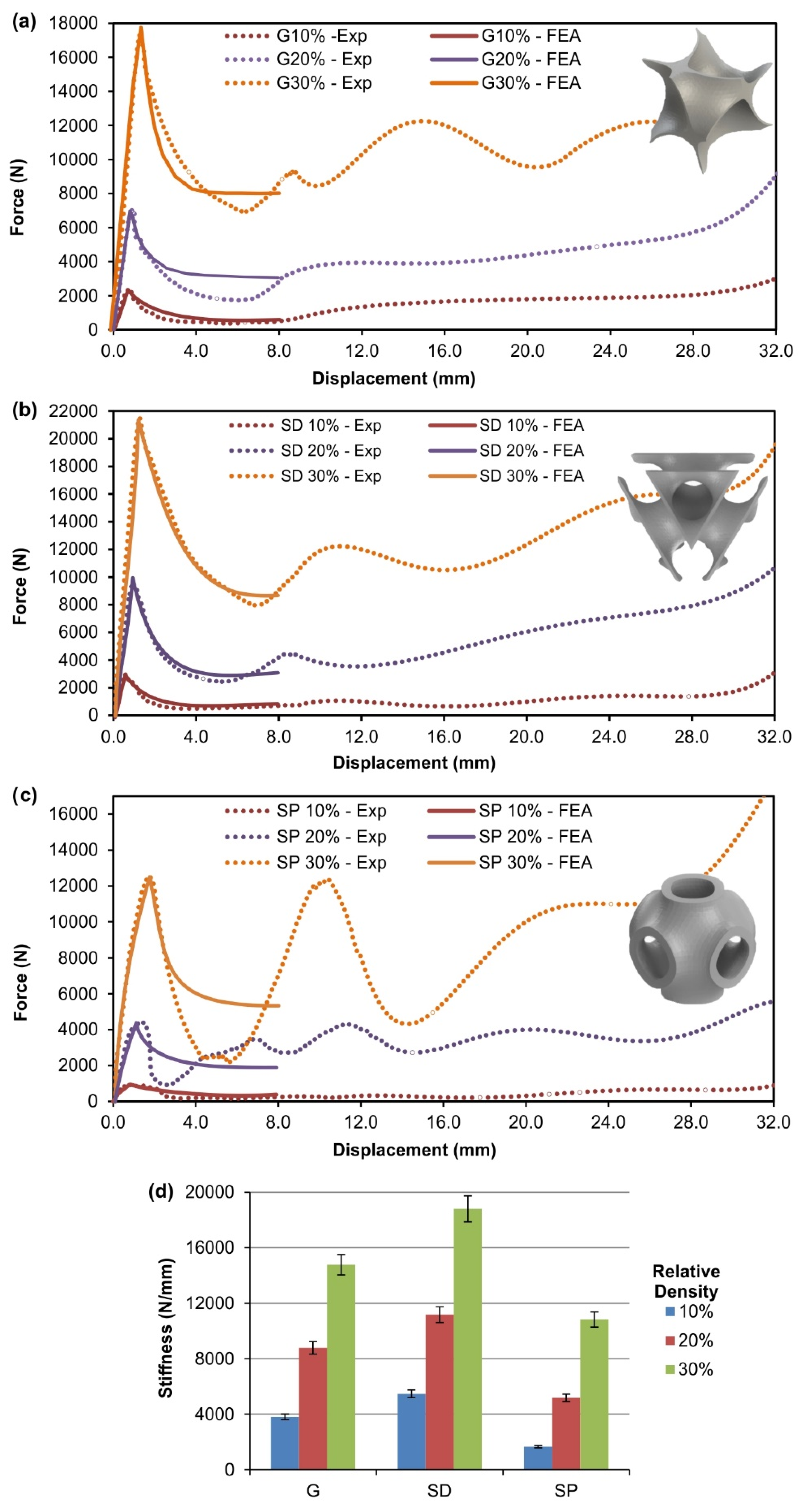
The architectures of the selected cellular units govern whether the structures deform in a stretching-dominated mode or a bending-dominated mode [3]. A stretching-dominated cellular structure demonstrates higher strength and stiffness compared to a bending-dominated structure at the same relative density. The typical load-displacement responses of FFF printed Gyroid, Schwarz Diamond and Schwarz primitive structures, under uniaxial compressive loading is illustrated in Figure 7. It can be easily observed that the Schwarz Diamond and Gyroid structures revealed a clear stretching-dominated behavior, in Figure 7a,b, respectively. Schwarz primitive structures displayed a hybrid behavior between the stretching- and bending-dominated modes. This could be verified by the decrease of high loads, revealing localized bending and uniform stresses at both low and high relative density, as shown in Figure 7c. These fluctuations in strength are more noticeable for the 30% relative density.
It is shown that the Gyroid, Schwarz diamond and Schwarz primitive TPMS structures, have reached an ultimate compression load of 17,415 N, 21,504 N and 12,520 N, respectively. The maximum deformation was set 32 mm for all the specimens and as they further deform this leads to the densification of the structures. In Figure 7d, the results portray clearly that Schwarz Diamond structures showed the highest stiffness for all relative densities. The Gyroid architecture specimens revealed a slight decrease of 21% compared to SD. SP demonstrated a 42% decrease compared to SD at relative density of 30%. This difference increases for low relative densities due to the magnification of the size effect. This phenomenon was expected since the stiffness is expressed as the ratio of force to displacement and is directly affected by the size effect.
The simulation results of the force-displacement data have been plotted as illustrated in Figure 7, where it can be easily seen that these values converged with the experimental results. Thus, the assumption of a combined linear and viscoelastic material model of each TPMS structure was considered correct. The mesh quality and the material properties were sufficiently accurate in the present study, since the differences between the experimental post-softening and numerical relaxation response were scarcely noticeable, as shown in Figure 7. Figure 7 also shows the FEA results simulating viscoelastic responses of Gyroid, SD and SP structures at different relative densities. Note that the decay is rapid in the beginning. This is due to the exponential function of the Prony series. In this case, relative modulus varied from 0.8 to 1.2, while relaxation time was assumed 150 s. The response becomes asymptotic, showing that the maximum force at time equal to 150 s decreases to nearly half of the maximum force at the beginning of the solution, as expected. It should be noted that relaxation starts to occur at the beginning of the solution and this model experiences a multiaxial state of stress, explaining why the latter force value is not exactly half of the ultimate strength.
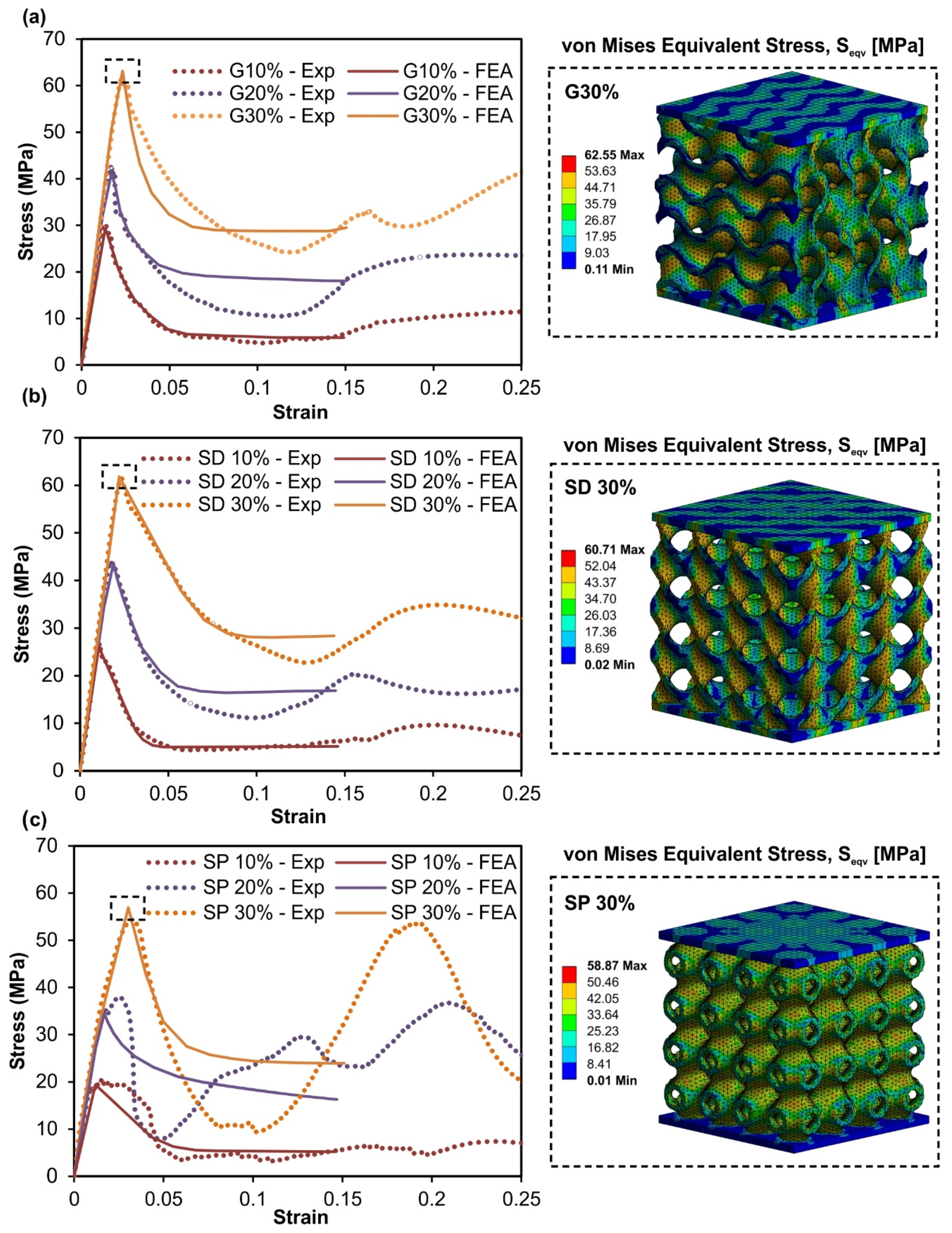
Figure 8 shows the comparison of the experimental and FEA stress-strain curves. Prony series have been used to investigate the relation between cellular architecture and its effective behavior. Table 5 shows the compressive yield strength values and the base material uniaxial elastic modulus at different relative densities. As shown in Table 5, the compressive yield strength values of the TPMS structures are significantly lower compared to those of the base thermoplastic PLA (yield strength at 60 MPa).
The finite element analysis results were similar to the experimental data measured for Gyroid and Schwarz Diamond structures. Schwarz Primitive specimen’s FEA results were similar to the experimental results of the elastic section of the stress-strain diagram. The E modulus mean value was determined to be 3550 MPa and this was in agreement with nanoindentation and compression results and another work on 3D printed PLA [36]. However, due to the influence of manufacturing method (FFF printing) and size effect, the effective elastic modulus ranges between 2250–2928 MPa for TPMS structures (Table 5). This phenomenon is similar to the impact of the size effect on stiffness of the TPMS structures. Since these particular architectures, reveal a post-softening beyond the yield point, the finite element analysis returned comparable results to those of the experiments in the early stage of viscoelastic deformation. Thus, the results of the experimental and FEA almost coincide up to 25% of the ultimate strain, as shown in Figure 8.
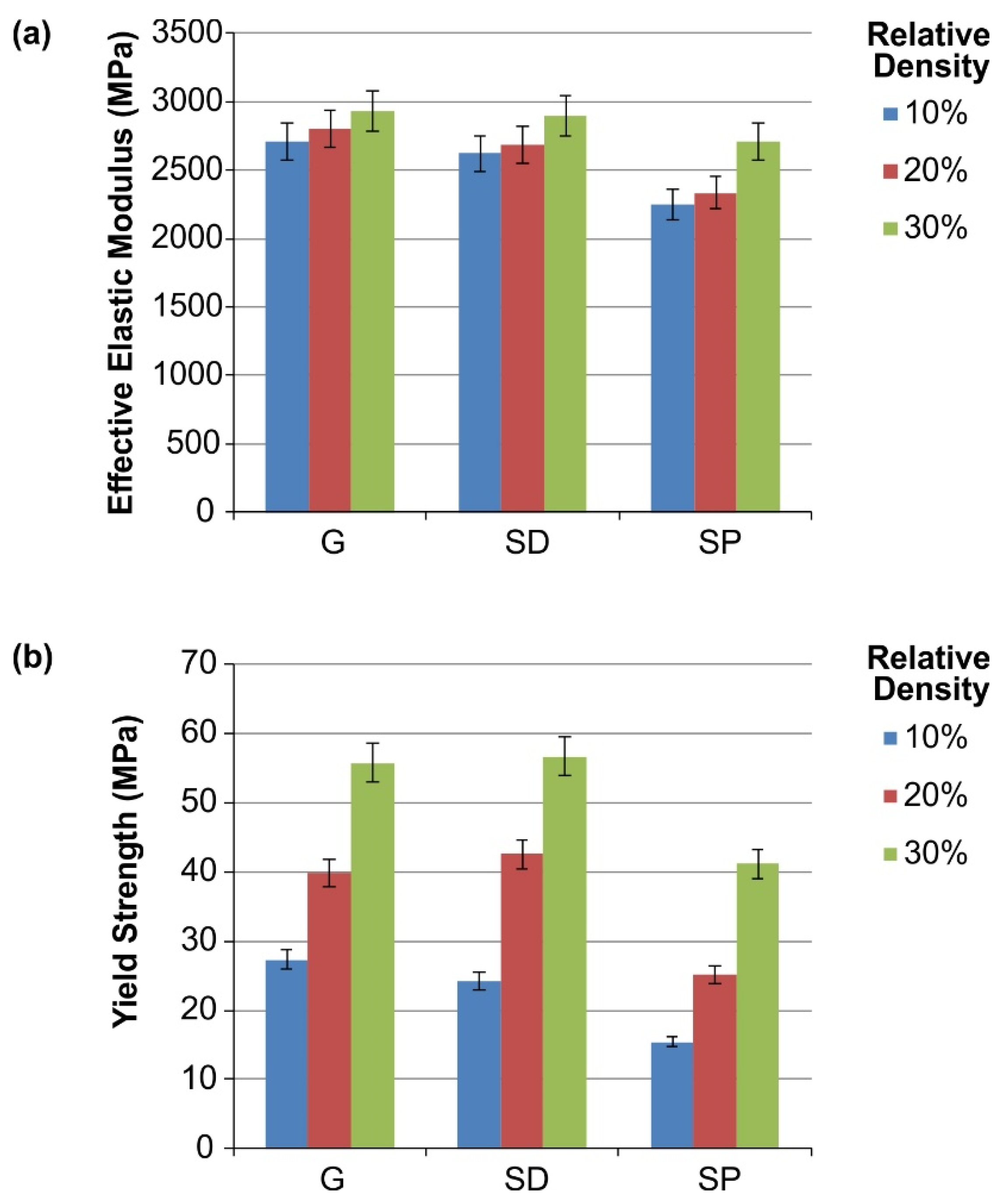
Αs presented in Figure 9a, the Gyroid structure generally exhibited higher effective elastic modulus compared to the other TPMS structures. It can be observed that the Schwarz Primitive structures were influenced by the size effect compare to the Schwarz Diamond and Gyroid structures, since the percentage reduction reached up to 17% between SP30 and SP10. In Figure 9b, the Schwarz Diamond structure demonstrated the highest strength, followed by the Gyroid, while the lowest strength was observed for the Schwarz Primitive specimens. It is worth noting that as the relative density decreases, the mechanical properties deteriorate, regardless of the TPMS structure, due to the intense impact of size effect.
To sum up, the mechanical properties of 3D printed TPMS lattice structures differ from the mechanical properties of the filament material and 3D printed PLA cylindrical specimens. This difference was further increased when the part contains lattice structures [20,45,46]. When an object contains lattice structures with low relative density, the phenomenon of size effect becomes apparent and the mechanical properties of the structure are significantly reduced. The mechanical properties of the structures studied in this work were influenced by both the 3D printing procedure and the size effect. The first concern was to reduce the size effect, hence the length of unit cells was selected at 12.5 mm, while the thickness values ranged between 0.6 to 2 mm. Solid parts were also used in the structure to enhance the mechanical properties exploiting the advantages of sandwich-like structures, with upper and lower plates of 2 mm thickness [47]. In order to minimize the 3D printing effect in the mechanical properties, the smallest available nozzle (0.4 mm) was used for 3D printing to achieve the minimum layer thickness. An attempt was also made to find the optimum print orientation, always keeping in mind the limitations of the FFF printing technique and the complexity of the TPMS surfaces. Hence, the ZXY orientation was chosen according to ISO/ASTM52921-13 [48], which leads to optimal mechanical behavior for compression testing.

3.4. Energy Absorption of the FFF TPMS Structures

The energy absorption study of a lattice structure is essential due to the fact that the high energy absorption rate is a fundamental property for these structures and their applications [3,20,49]. For this reason, it is important to calculate the energy absorption per unit volume regardless the size of test specimens for each TPMS structure.
Since there is no corresponding standardization for the absorption of energy in plastic cellular materials, the methodology for calculating the energy absorption for metal cellular materials standardization was used [48]. This means that the energy absorption per volume of each structure during a compressive load is calculated by the equation:
W v = 0 ε 0 σ d ε
where, Wv is the amount of energy absorption per volume (MJ/m3), ε0 is the maximum strain limit, which refers to the maximum strain before densification occurs, that is, 60%, σ is the compressive stress (MPa or N/mm2) and ε is the strain. Moreover, with the appropriate transformation of the above equation (Equation (1)) the energy absorption per mass can be calculated for each structure of the specific energy absorption (SEA) Wm (kJ/kg). The necessary transformation for this calculation is:
W m = W v ρ
where ρ is the density of the 3D printing material.
Based on the above equations, the energy absorption of each structure is inextricably linked to the surface areas below the stress-strain curves extracted by compressive loading experiments. After extracting the stress-strain curves from compression tests supported by FEA, the energy absorption per volume for each lattice structure and relative density was calculated by numerically solving the equation. The trapezoidal method was used for the numerical solution of the integral of the equations. More specifically, the energy absorption value was calculated for each structure and relative density by the following formula:
W v = 0 ε 60 % σ d ε = 1 2 [ σ ( 0 ) + 2 σ ( ε 1 ) + + σ ( ε 60 % ) ] 1 n
where n is the number of points and it was determined from the experimental stress-strain curves. This number was around 14,400 that is, the displacement (60% of strain) of the specimens was given by the testing machine as 14,400 points in order to simulate the quasi-static mode of the experiment.
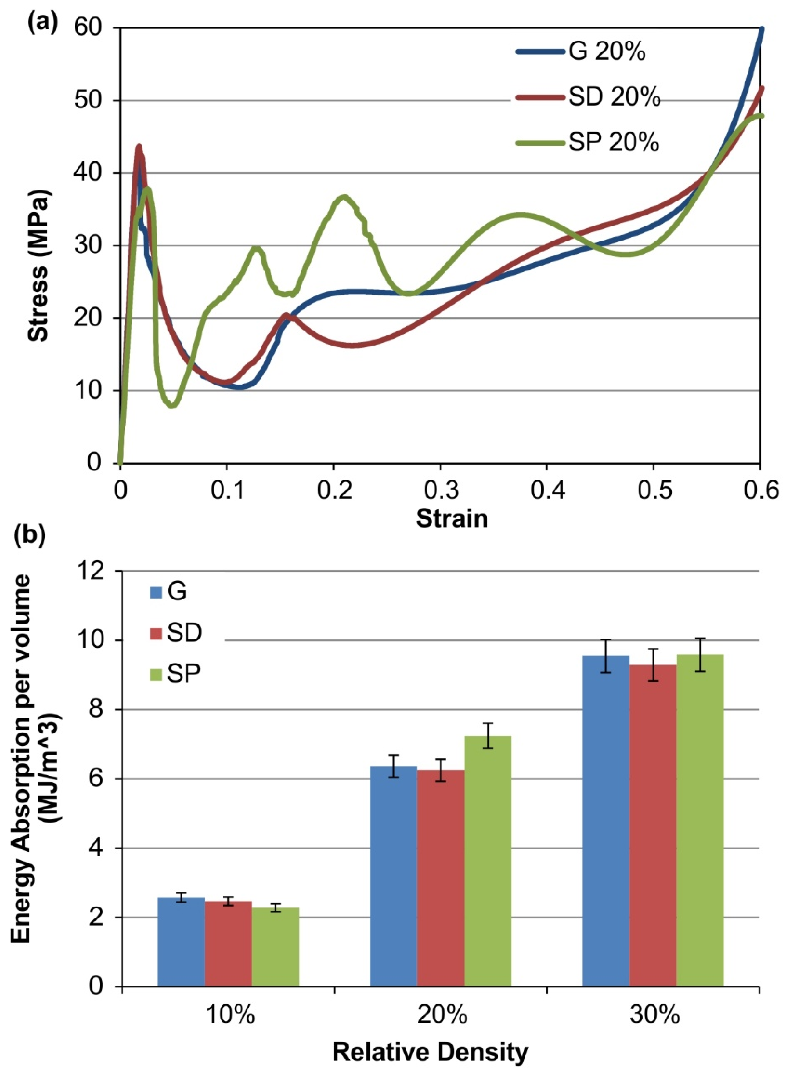
Figure 10a portrays an indicative stress-strain diagram for all TPMS structures at relative density of 20%. The numerical results for energy absorption per unit volume are shown in Figure 10b. It is worth mentioning that energy absorption is measured up to 60% strain, hence the highest amount of energy absorption derived from the plastic deformation section. Moreover, the energy absorption performance of all the TPMS structures was configured by three distinct regions of the stress-strain diagram. Initially there is the elastic section which provided significant amount of energy due to maximum compressive strength, then the post-softening effect occurred reducing the energy absorption rate. Finally, a plateau-like was created and large amount of energy were absorbed until the densification.
The results reveal that Schwarz Primitive structures absorbed the highest amount of energy for 20% and 30% relative densities, however, the Schwarz Primitive structures with 10% relative density were brittle leading to reduced strength, thus to lower energy absorption (Figure 10b). Furthermore, these structures absorbed lower amounts of energy at the elastic region, however beyond yielding point the energy absorption rate was increased, especially after post-softening effect, that is, after 8%. Gyroid structures had a remarkable energy absorption performance for all relative densities due to their high yield strength and the early densification that occurred at these specimens. Schwarz Diamond structures absorbed the lowest amount of energy from these three structures, despite the fact that they had demonstrated the highest compressive strength. It is worth mentioning that extensive post-softening phenomena led to these results. Overall, the under study TPMS structures have demonstrated high energy absorption amounts and could be considered as promising candidates for impact applications, where high crashworthiness structures are needed.

4. Conclusions

This paper investigated the mechanical behavior of FFF printed lattice structures, which are included in the TPMS family (Gyroid, Schwarz Diamond and Schwarz Primitive). Specimens were FFF printed as sandwich-like structures and their mechanical behavior was determined with quasi-static compressive experiments, supported by finite element analysis. The stress-strain behavior in the FE model for the 3D printed TPMS structures was determined by curve-fitting the experimental compression data. Schwarz Primitive structure was mostly affected by the size effect and this led to a significant deterioration of its structural integrity. Schwarz Primitive geometry exhibited a similar to bending-dominated behavior with the presence of strong shear stresses, resulting in diagonal failure of the specimens. However, Schwarz Primitive structure have shown the highest amount of absorbed energy among the other TPMS structures, since it continued to withstand high loads after yielding point. Gyroid structure revealed the highest performance in terms of stiffness and elastic modulus. The boundaries of the Gyroid unit cell were the weakest regions and the failure typically initiated from there. In addition, Gyroid structures have shown substantial energy absorption rate, due to the combination of their high yield strength and limited post-softening effect. Schwarz Diamond structures portrayed the highest strength among the studied TPMS structures. This phenomenon could be possibly attributed to the fact that Schwarz Diamond structures have superior material distribution within the volume’s domain and therefore the stresses could be distributed more effectively. Schwarz Diamond and Gyroid structures were moderately deteriorated from the size effect due to the novel sandwich-like structures, which helped to maintain their structural integrity. Therefore, both Schwarz Diamond and Gyroid structures revealed a clear stretching-dominated behavior.

Author Contributions

Conceptualization, N.K., K.T. and D.T.; methodology, N.K. and K.T.; software, N.K., K.T.; formal analysis, N.K., K.T. and D.T.; investigation, N.K., K.T. and D.T.; resources, N.K.; data curation, N.K.; writing—original draft preparation, N.K.; writing—review and editing, K.T. and D.T.; supervision, K.T. and D.T.; project administration, D.T. All authors have read and agreed to the published version of the manuscript.

Funding

This research received no external funding.

Conflicts of Interest

The authors declare no conflict of interest.

References

  1. Gebisa, A.W.; Lemu, H.G. A case study on topology optimized design for additive manufacturing. IOP Conf. Ser. Mater. Sci. Eng. 2017, 276, 12026. [Google Scholar] [CrossRef] [Green Version]
  2. Rosso, S.; Savio, G.; Uriati, F.; Meneghello, R.; Concheri, G. Optimization Approaches in Design for Additive Manufacturing. Proc. Des. Soc. Int. Conf. Eng. Des. 2019, 1, 809–818. [Google Scholar] [CrossRef] [Green Version]
  3. Gibson, L.J.; Ashby, M.F. Cellular Solids: Structure & Properties; Pergamon Press: Oxford, UK, 1988; ISBN 0-08-036607-4. [Google Scholar]
  4. González-Henríquez, C.M.; Sarabia-Vallejos, M.A.; Rodriguez-Hernandez, J. Polymers for additive manufacturing and 4D-printing: Materials, methodologies, and biomedical applications. Prog. Polym. Sci. 2019, 94, 57–116. [Google Scholar] [CrossRef]
  5. Mahmoud, D.; Elbestawi, M.A. Lattice Structures and Functionally Graded Materials Applications in Additive Manufacturing of Orthopedic Implants: A Review. J. Manuf. Mater. Process. 2017, 1, 13. [Google Scholar] [CrossRef]
  6. Kladovasilakis, N.; Tsongas, K.; Tzetzis, D. Finite Element Analysis of Orthopedic Hip Implant with Functionally Graded Bioinspired Lattice Structures. Biomimetics 2020, 5, 44. [Google Scholar] [CrossRef] [PubMed]
  7. Khanoki, S.A.; Pasini, D. Fatigue design of a mechanically biocompatible lattice for a proof-of-concept femoral stem. J. Mech. Behav. Biomed. Mater. 2013, 22, 65–83. [Google Scholar] [CrossRef] [Green Version]
  8. Elomaa, L.; Teixeira, S.; Hakala, R.; Korhonen, H.; Grijpma, D.W.; Seppälä, J.V. Preparation of poly(ε-caprolactone)-based tissue engineering scaffolds by stereolithography. Acta Biomater. 2011, 7, 3850–3856. [Google Scholar] [CrossRef] [PubMed]
  9. Kantaros, A.; Chatzidai, N.; Karalekas, D. 3D printing-assisted design of scaffold structures. Int. J. Adv. Manuf. Technol. 2016, 82, 559–571. [Google Scholar] [CrossRef]
  10. Cabrera, M.S.; Sanders, B.B.; Goor, O.J.; Driessen-Mol, A.A.; Oomens, C.W.; Baaijens, F.P. Computationally Designed 3D Printed Self-Expandable Polymer Stents with Biodegradation Capacity for Minimally Invasive Heart Valve Implantation: A Proof-of-Concept Study. 3D Print. Addit. Manuf. 2017, 4, 19–29. [Google Scholar] [CrossRef]
  11. Melchiorri, A.J.; Hibino, N.; Best, C.A.; Yi, T.; Lee, Y.U.; Kraynak, C.A.; Kimerer, L.K.; Krieger, A.; Kim, P.; Breuer, C.K.; et al. 3D-Printed Biodegradable Polymeric Vascular Grafts. Adv. Health Mater. 2016, 5, 319–325. [Google Scholar] [CrossRef] [PubMed]
  12. Tao, W.; Leu, M.C. Design of lattice structure for additive manufacturing. In Proceedings of the 2016 International Symposium on Flexible Automation (ISFA), Cleveland, OH, USA, 1–3 August 2016; pp. 325–332. [Google Scholar] [CrossRef]
  13. Hurt, C.; Brandt, M.; Priya, S.S.; Bhatelia, T.; Patel, J.; Selvakannan, P.; Bhargava, S. Combining additive manufacturing and catalysis: A review. Catal. Sci. Technol. 2017, 7, 3421–3439. [Google Scholar] [CrossRef]
  14. Boomsma, K.; Poulikakos, D.; Zwick, F. Metal foams as compact high performance heat exchangers. Mech. Mater. 2003, 35, 1161–1176. [Google Scholar] [CrossRef]
  15. Simone, A.; Gibson, L. Effects of solid distribution on the stiffness and strength of metallic foams. Acta Mater. 1998, 46, 2139–2150. [Google Scholar] [CrossRef]
  16. Maskery, I.; Sturm, L.; Aremu, A.; Panesar, A.; Williams, C.; Tuck, C.; Wildman, R.; Ashcroft, I.; Hague, R. Insights into the mechanical properties of several triply periodic minimal surface lattice structures made by polymer additive manufacturing. Polymer 2018, 152, 62–71. [Google Scholar] [CrossRef]
  17. Kaur, M.; Yun, T.G.; Han, S.M.; Thomas, E.L.; Kim, W.S. 3D printed stretching-dominated micro-trusses. Mater. Des. 2017, 134, 272–280. [Google Scholar] [CrossRef]
  18. Bauer, J.; Meza, L.R.; Schaedler, T.A.; Schwaiger, R.; Zheng, X.; Valdevit, L. Nanolattices: An Emerging Class of Mechanical Metamaterials. Adv. Mater. 2017, 29, 1701850. [Google Scholar] [CrossRef]
  19. Zhao, M.; Liu, F.; Fu, G.; Zhang, D.Z.; Zhang, T.; Zhou, H. Improved Mechanical Properties and Energy Absorption of BCC Lattice Structures with Triply Periodic Minimal Surfaces Fabricated by SLM. Materials 2018, 11, 2411. [Google Scholar] [CrossRef] [Green Version]
  20. Al-Ketan, O.; Rowshan, R.; Abu Al-Rub, R.K. Topology-mechanical property relationship of 3D printed strut, skeletal, and sheet based periodic metallic cellular materials. Addit. Manuf. 2018, 19, 167–183. [Google Scholar] [CrossRef]
  21. Li, D.; Liao, W.; Dai, N.; Xie, Y.M. Comparison of Mechanical Properties and Energy Absorption of Sheet-Based and Strut-Based Gyroid Cellular Structures with Graded Densities. Materials 2019, 12, 2183. [Google Scholar] [CrossRef] [PubMed] [Green Version]
  22. Abueidda, D.W.; Elhebeary, M.; Shiang, C.-S.A.; Pang, S.; Abu Al-Rub, R.K.; Jasiuk, I.M. Mechanical properties of 3D printed polymeric Gyroid cellular structures: Experimental and finite element study. Mater. Des. 2019, 165, 107597. [Google Scholar] [CrossRef]
  23. Zheng, X.; Fu, Z.; Du, K.; Wang, C.; Yi, Y. Minimal surface designs for porous materials: From microstructures to mechanical properties. J. Mater. Sci. 2018, 53, 10194–10208. [Google Scholar] [CrossRef]
  24. Al-Ketan, O.; Rezgui, R.; Rowshan, R.; Du, H.; Fang, N.X.; Abu Al-Rub, R.K. Microarchitected Stretching-Dominated Mechanical Metamaterials with Minimal Surface Topologies. Adv. Eng. Mater. 2018, 20, 1800029. [Google Scholar] [CrossRef]
  25. Chua, C.K.; Yeong, W.Y.; Tan, M.J.; Liu, E.J.; Tor, S.B. Study of the influence of 3D printing parameters on the mechanical properties of PLA. In Proceedings of the 3rd International Conference on Progress in Additive Manufacturing, Nanyang Executive Centre, Singapore, 14–17 May 2018; pp. 547–552. [Google Scholar]
  26. Mohamed, O.A.; Masood, S.H.; Bhowmik, J.L. Optimization of fused deposition modeling process parameters: A review of current research and future prospects. Adv. Manuf. 2015, 3, 42–53. [Google Scholar] [CrossRef]
  27. Popescu, D.; Zapciu, A.; Amza, C.; Baciu, F.; Marinescu, R. FDM process parameters influence over the mechanical properties of polymer specimens: A review. Polym. Test. 2018, 69, 157–166. [Google Scholar] [CrossRef]
  28. Zhang, J.W.; Peng, A.H. Process-Parameter Optimization for Fused Deposition Modeling Based on Taguchi Method. Adv. Mater. Res. 2012, 538, 444–447. [Google Scholar] [CrossRef]
  29. Ang, K.C.; Leong, K.F.; Chua, C.K.; Chandrasekaran, M. Investigation of the mechanical properties and porosity relationships in fused deposition modelling-fabricated porous structures. Rapid Prototyp. J. 2006, 12, 100–105. [Google Scholar] [CrossRef]
  30. Da Silva, D.; Kaduri, M.; Poley, M.; Adir, O.; Krinsky, N.; Shainsky-Roitman, J.; Schroeder, A. Biocompatibility, biodegradation and excretion of polylactic acid (PLA) in medical implants and theranostic systems. Chem. Eng. J. 2018, 340, 9–14. [Google Scholar] [CrossRef]
  31. Al-Ketan, O.; Abu Al-Rub, R.K. Multifunctional Mechanical Metamaterials Based on Triply Periodic Minimal Surface Lattices: A review. Adv. Eng. Mater. 2019, 21, 1900524. [Google Scholar] [CrossRef]
  32. Lord, E.A.; Mackay, A.L. Periodic minimal surfaces of cubic symmetry. Curr. Sci. 2003, 85, 346–362. [Google Scholar]
  33. Panesar, A.; Abdi, M.; Hickman, D.; Ashcroft, I. Strategies for functionally graded lattice structures derived using topology optimisation for Additive Manufacturing. Addit. Manuf. 2018, 19, 81–94. [Google Scholar] [CrossRef]
  34. Mansour, G.; Tsongas, K.; Tzetzis, D.; Tzikas, K. Dynamic Mechanical Characterization of Polyurethane/Multiwalled Carbon Nanotube Composite Thermoplastic Elastomers. Polym. Plast. Technol. Eng. 2017, 56, 1505–1515. [Google Scholar] [CrossRef]
  35. Mansour, M.; Tsongas, K.; Tzetzis, D.; Antoniadis, A. Mechanical and Dynamic Behavior of Fused Filament Fabrication 3D Printed Polyethylene Terephthalate Glycol Reinforced with Carbon Fibers. Polym. Technol. Eng. 2018, 57, 1715–1725. [Google Scholar] [CrossRef]
  36. Mansour, M.; Tsongas, K.; Tzetzis, D. Measurement of the mechanical and dynamic properties of 3D printed polylactic acid reinforced with graphene. Polym. Plast. Technol. Eng. 2018, 58, 1234–1244. [Google Scholar] [CrossRef]
  37. Tsongas, K.; Tzetzis, D.; Mansour, G. Mechanical and vibration isolation behaviour of acrylonitrile-butadiene rubber/multi-walled carbon nanotube composite machine mounts. Plast. Rubber Compos. 2017, 46, 458–468. [Google Scholar] [CrossRef]
  38. Tzetzis, D.; Tsongas, K.; Mansour, G. Determination of the Mechanical Properties of Epoxy Silica Nanocomposites through FEA-Supported Evaluation of Ball Indentation Test Results. Mater. Res. 2017, 20, 1571–1578. [Google Scholar] [CrossRef] [Green Version]
  39. Walley, S.M.; Field, J.E. Strain rate sensitivity of polymers in compression from low to high rates. DYMAT J. 1994, 1, 211–227. [Google Scholar]
  40. Khan, K.A.; Abu Al-Rub, R.K. Viscoelastic properties of architected foams based on the Schoen IWP triply periodic minimal surface. Mech. Adv. Mater. Struct. 2020, 27, 775–788. [Google Scholar] [CrossRef]
  41. Oliver, W.; Pharr, G. An improved technique for determining hardness and elastic modulus using load and displacement sensing indentation experiments. J. Mater. Res. 1992, 7, 1564–1583. [Google Scholar] [CrossRef]
  42. Granta Material Intelligence. Granta’s CES EduPack; Granta Design Limited: Cambridge, UK, 2007. [Google Scholar]
  43. Tzetzis, D.; Mansour, G.; Tsiafis, I.; Pavlidou, E. Nanoindentation measurements of fumed silica epoxy reinforced nanocomposites. J. Reinf. Plast. Compos. 2013, 32, 160–173. [Google Scholar] [CrossRef]
  44. ASTM. ISO/ASTM 52921: 2013 Standard Terminology for Additive Manufacturing–Coordinate Systems and Test Methodologies; ASTM International: West Conshohocken, PA, USA, 2013. [Google Scholar] [CrossRef]
  45. Meza, L.R.; Das, S.; Greer, J.R. Strong, lightweight, and recoverable three-dimensional ceramic nanolattices. Science 2014, 345, 1322–1326. [Google Scholar] [CrossRef] [PubMed] [Green Version]
  46. Bauer, J.; Hengsbach, S.; Tesari, I.; Schwaiger, R.; Kraft, O. High-strength cellular ceramic composites with 3D microarchitecture. Proc. Natl. Acad. Sci. USA 2014, 111, 2453–2458. [Google Scholar] [CrossRef] [PubMed] [Green Version]
  47. Mahshid, R.; Hansen, H.N.; Højbjerre, K.L. Strength analysis and modeling of cellular lattice structures manufactured using selective laser melting for tooling applications. Mater. Des. 2016, 104, 276–283. [Google Scholar] [CrossRef] [Green Version]
  48. Mechanical Testing of Metals—Ductility Testing—Compression Test for Porous and Cellular Metals; ISO 13314:2011; International Organization for Standardization: Geneva, Switzerland, 2011–2012.
  49. Sychov, M.; Lebedev, L.; Dyachenko, S.; Nefedova, L. Mechanical properties of energy-absorbing structures with triply periodic minimal surface topology. Acta Astronaut. 2018, 150, 81–84. [Google Scholar] [CrossRef]
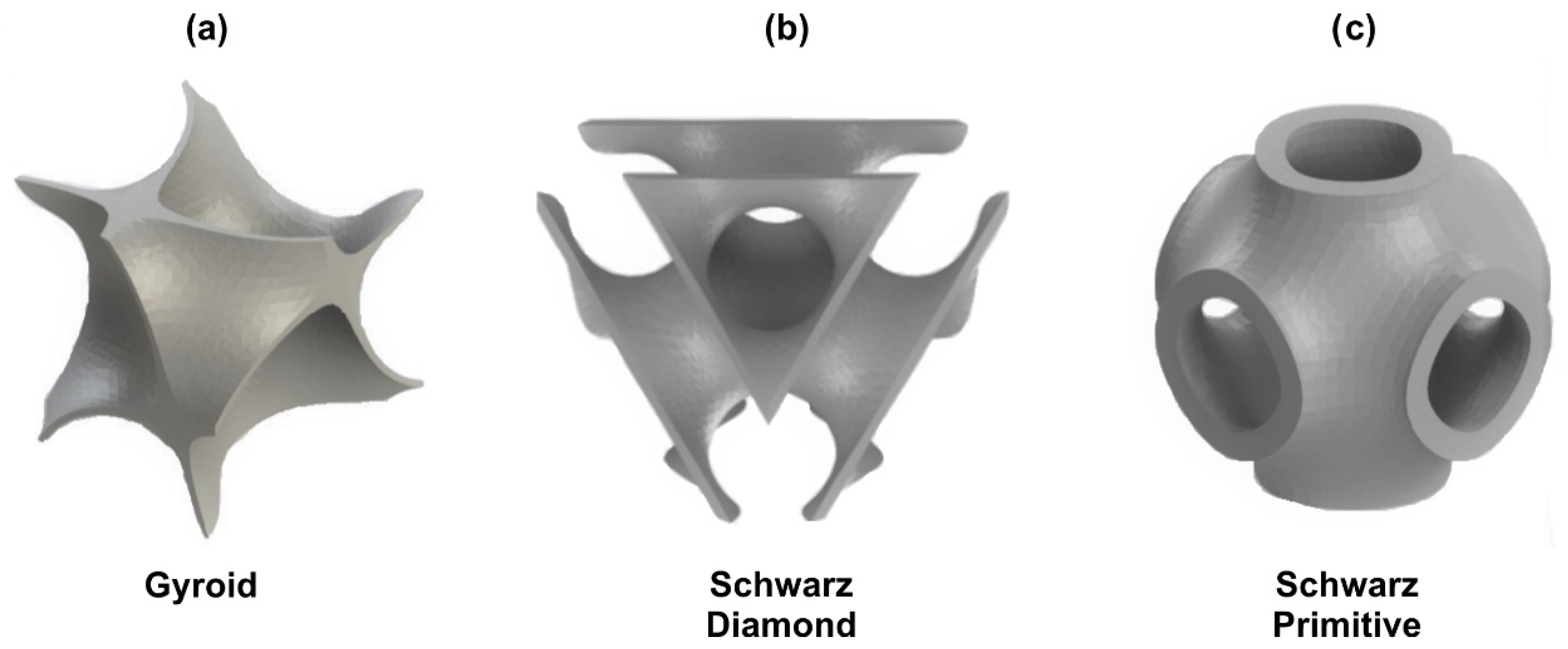
Figure 1. Unit cell of each Triply Periodic Minimal Surface (TPMS) structure: (a) Gyroid, (b) Schwarz Diamond (SD), (c) Schwarz Primitive (SP).
Jcs 05 00058 g001
Figure 2. 3D CAD models of Gyroid, SD and SP TPMS structures (4 × 4 × 4 unit cells).
Jcs 05 00058 g002
Figure 3. (a) Force-depth results of the nanoindentation tests of the polylactic acid (PLA) filament material and (b) compressive stress-strain results of 3D printed cylindrical PLA specimens.
Jcs 05 00058 g003
Figure 4. 3D-Printed TPMS specimens with different relative densities.
Jcs 05 00058 g004
Figure 5. Comparison of deformation frames at 0%, 5% and 10% strain for 20% relative density Gyroid, Schwarz Diamond and Schwarz Primitive structures.
Jcs 05 00058 g005
Figure 6. Fracture areas at 15% strain for (a,b) Schwarz Primitive, (c,d) Gyroid and (e,f) Schwarz Diamond TPMS structures.
Jcs 05 00058 g006
Figure 7. Comparison between finite element analysis (FEA)-determined and experimental compression tests for: (a) Gyroid, (b) SD, (c) SP TPMS structures and (d) a bar chart of the stiffness values for all the TPMS structures.
Jcs 05 00058 g007
Figure 8. Comparison between experimental and FEA-determined stress-strain curves for (a) Gyroid, (b) Schwarz Diamond and (c) Schwarz Primitive TPMS structures at different relative densities.
Jcs 05 00058 g008
Figure 9. (a) Effective elastic modulus and (b) compressive yield strength for each TPMS structure.
Jcs 05 00058 g009
Figure 10. (a) Indicative Stress-strain curves for all the TPMS structures at relative density of 20% (up to 60% strain); (b) Energy absorption per volume comparison between different lattice structures (up to 60% strain).
Jcs 05 00058 g010
Table 1. Element Thickness of Gyroid, SD and SP TPMS structures.
TPMS StructureRelative Density
10%20%30%
Thickness Gyroid0.65 mm1.3 mm1.95 mm
Thickness Schwarz Diamond0.67 mm1.33 mm2 mm
Thickness Schwarz Primitive0.54 mm1.07 mm1.61 mm
Table 2. General 3D printing parameters of all the TPMS specimens.
Printing ParametersValues
Layer Height0.2 mm
Wall Thickness0.54–2 mm (depending on applied unit cell)
Infill100%
Printing Temperature210 °C
Printing Speed60 mm/s
Table 3. Properties of the filament material.
Properties PLADensity (g/cm3)Elastic Modulus from Nanoindentation Test (MPa)Elastic Modulus from Compression Tests (MPa)Compressive Yield Strength (MPa)
1.253700 ± 1153400 ± 13060 ± 5
Table 4. Structural Properties of 3D Printed Specimens.
TPMS Relative Density of Lattice VolumeActual Relative DensityWeight of Specimen (gr.)Time of Printing
Gyroid10%16.7%28.18~4 h
20%26.1%44.04~5 h and 30 min.
30%35%59.06~7 h and 30 min.
Schwarz Diamond10%16.7%28.18~4 h
20%26.1%44.04~5 h and 30 min.
30%35%59.06~7 h and 30 min.
Schwarz Primitive10%16.7%28.18~4 h
20%26.1%44.04~5 h and 30 min.
30%35%59.06~7 h and 30 min.
Table 5. Mechanical Properties of the finite element analysis (FEA) printed TPMS structures.
Type of SpecimenEffective Elastic Modulus
Elat (MPa)
Compressive Yield Strength (Experimental)
σexp (MPa)
Compressive Yield Strength (FEA)
σfea (MPa)
Gyroid (ρ = 10%)270827.3327.11
Gyroid (ρ = 20%)280439.8239.89
Gyroid (ρ = 30%)292855.7653.55
Schwarz Diamond (ρ = 10%)262424.1725.83
Schwarz Diamond (ρ = 20%)268542.5239.32
Schwarz Diamond (ρ = 30%)289656.6751.71
Schwarz Primitive (ρ = 10%)225015.4417.61
Schwarz Primitive (ρ = 20%)233425.1533.63
Schwarz Primitive (ρ = 30%)271341.1147.50
Publisher’s Note: MDPI stays neutral with regard to jurisdictional claims in published maps and institutional affiliations.