
Technological Aspects of Producing Surface Composites by Friction Stir Processing—A Review


Abstract
:1. Introduction
2. Methods
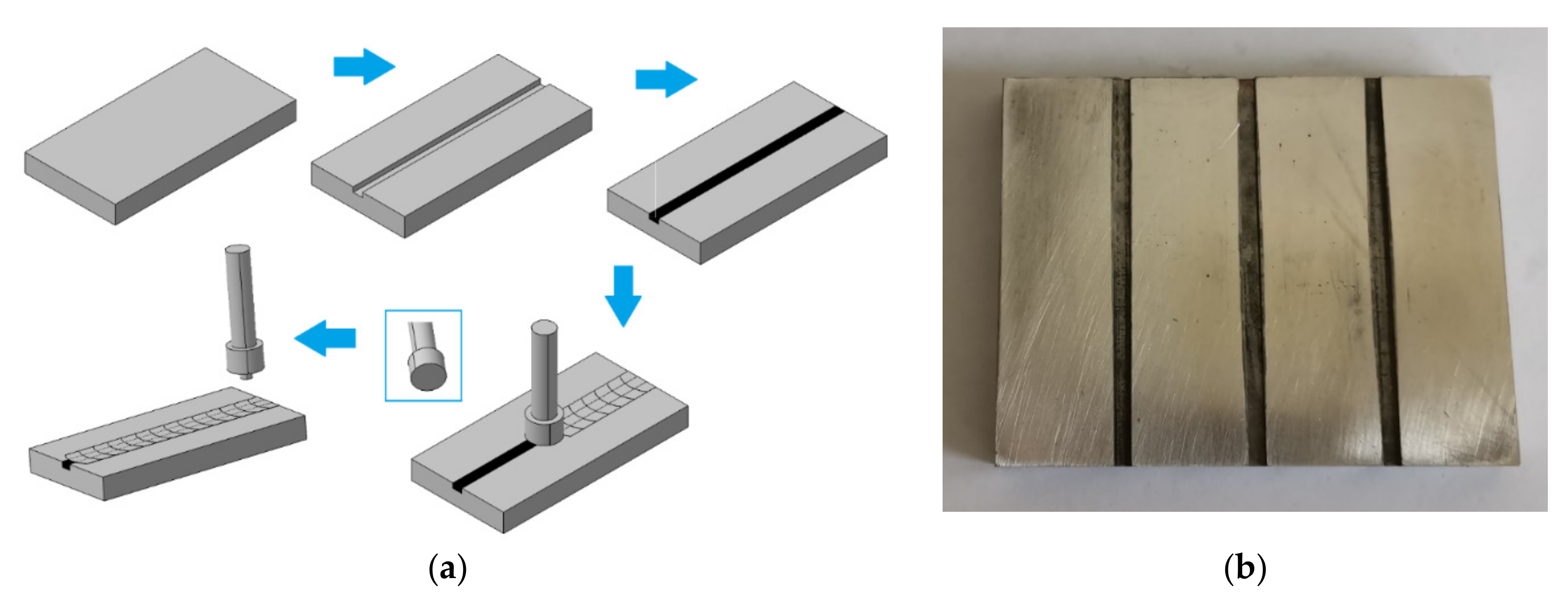
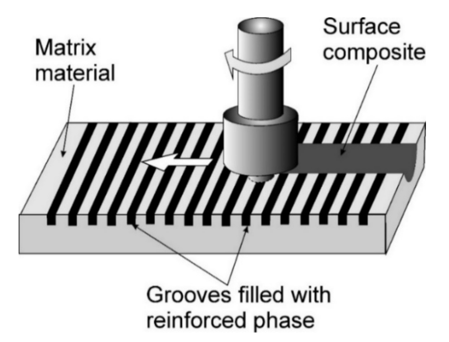
2.1. Groove Method
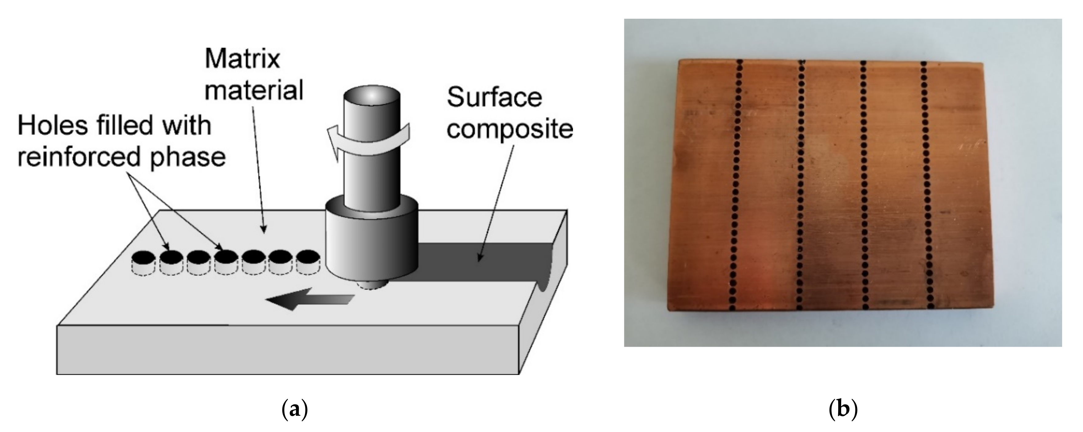
2.2. Hole Method
2.2.1. Zigzag Hole Pattern
2.2.2. The Hole Method with the Offset Line of Holes
2.2.3. A Deep Hole Drilled under the Surface
2.3. Sandwich Method
2.4. Direct Friction Stir Processing
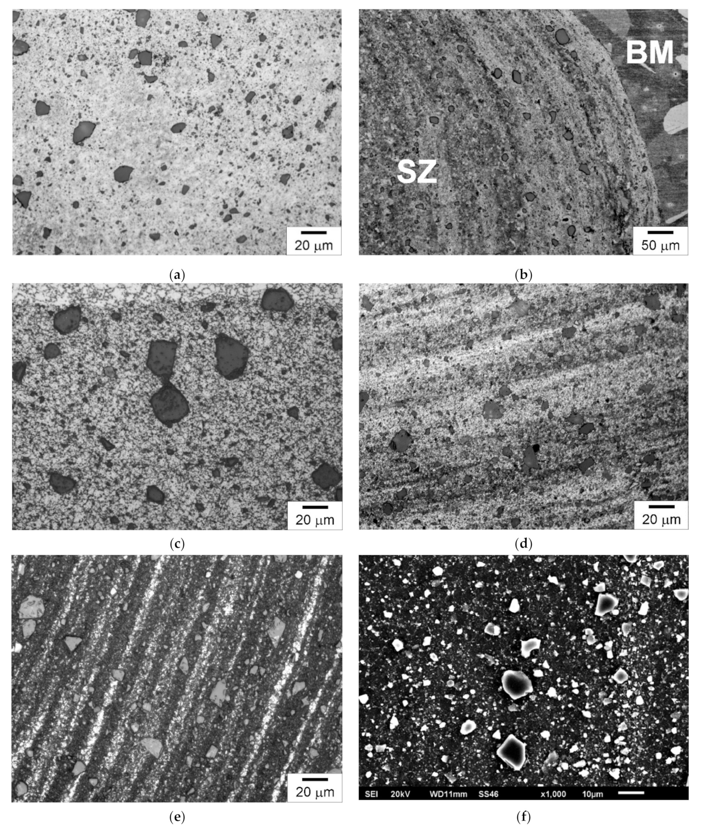
2.5. Modifying the Microstructure of Composites with FSP
3. Summary
4. Conclusions
Author Contributions
Funding
Conflicts of Interest
References
- Mishra, R.S.; Mahoney, M.W.; McFadden, S.X.; Mara, N.A.; Mukherjee, A.K. High strain rate superplasticity in a friction stir processed 7075 Al alloy. Scr. Mater. 1999, 42, 163–168. [Google Scholar] [CrossRef]
- Mishra, R.S.; Mahoney, M.W. Friction stir processing: A new grain refinement technique to achieve high strain rate superplasticity in commercial alloys. Mater. Sci. Forum 2001, 357–359, 507–514. [Google Scholar] [CrossRef]
- Thomas, W.M.; Nicholas, E.D.; Needham, J.C.; Murch, M.G.; Smith, P.T.; Dawes, C.J. Friction Stir Butt Welding. GB Patent 9125978, 6 December 1991. [Google Scholar]
- Kraiklang, R.; Onwong, J.; Santhaweesuk, C. Multi-performance characteristics of AA5052 + 10% SiC surface composite by friction stir processing. J. Compos. Sci. 2020, 4, 36. [Google Scholar] [CrossRef] [Green Version]
- Gan, Y.X.; Solomon, D.; Reinbolt, M. Friction stir processing of particle reinforced composite. Materials 2010, 3, 329–350. [Google Scholar] [CrossRef] [Green Version]
- Iwaszko, J.; Kudła, K. Friction stir processing of copper. In Proceedings of the 28th International Conference on Metallurgy and Materials (METAL 2019), Brno, Czech Republic, 22–24 May 2019; pp. 1051–1056. [Google Scholar] [CrossRef]
- Tamadon, A.; Pons, D.J.; Clucas, D. EBSD characterization of bobbin friction stir welding of AA6082-T6 aluminum alloy. Adv. Mater. Sci. 2020, 20, 49–74. [Google Scholar] [CrossRef]
- Wang, N.; Cao, L.; Yin, K. The microstructure, hardness and friction and wear behavior of AM60B magnesium alloy by friction stir processing. In Proceedings of the 2019 International Conference on Robotics, Intelligent Control and Artificial Intelligence, Shanghai, China, 20–22 September 2019; pp. 73–76. [Google Scholar] [CrossRef]
- Janeczek, A.; Tomków, J.; Fydrych, D. The influence of tool shape and process parameters on the mechanical properties of AW-3004 aluminium alloy friction stir welded joints. Materials 2021, 14, 3244. [Google Scholar] [CrossRef] [PubMed]
- Kosturek, R.; Śnieżek, L.; Torzewski, J.; Wachowski, M. The influence of welding parameters on macrostructure and mechanical properties of Sc-modified AA2519-T62 FSW joints. Manuf. Rev. 2020, 7, 28. [Google Scholar] [CrossRef]
- Sharma, V.; Prakash, U.; Manoj Kumar, B.V. Surface composites by friction stir processing: A review. J. Mater. Process. Technol. 2015, 224, 117–134. [Google Scholar] [CrossRef]
- Pouraliakbar, H.; Beygi, R.; Fallah, V.; Monazzah, A.H.; Mohammad, M.; Jandaghi, M.R.; Khalaj, G.; Da Silva, L.F.M.; Pavese, M. Processing of Al-Cu-Mg alloy by FSSP: Parametric analysis and the effect of cooling environment on microstructure evolution. Mater. Lett. 2022, 308, 131157. [Google Scholar] [CrossRef]
- Iwaszko, J.; Kudła, K.; Fila, K.; Strzelecka, M. The effect of friction stir processing (FSP) on the microstructure and properties of AM60 magnesium alloy. Arch. Metall. Mater. 2016, 61, 1209–1214. [Google Scholar] [CrossRef] [Green Version]
- Li, K.; Liu, X.; Zhao, Y. Research status and prospect of friction stir processing technology. Coatings 2019, 9, 129. [Google Scholar] [CrossRef] [Green Version]
- Sajed, M. Parametric study of two-stage refilled friction stir spot welding. J. Manuf. Process. 2016, 24, 307–317. [Google Scholar] [CrossRef]
- Ralls, A.M.; Kasar, A.K.; Menezes, P.L. Friction stir processing on the tribological, corrosion, and erosion properties of steel: A review. J. Manuf. Mater. Process. 2021, 5, 97. [Google Scholar] [CrossRef]
- Merah, N.; Abdul Azeem, M.; Abubaker, H.M.; Al-Badour, F.; Albinmousa, J.; Sorour, A.A. Friction stir processing influence on microstructure, mechanical, and corrosion behavior of steels: A review. Materials 2021, 14, 5023. [Google Scholar] [CrossRef] [PubMed]
- Mishra, R.S.; Ma, Z.Y.; Charit, I. Friction stir processing: A novel technique for fabrication of surface composite. Mater. Sci. Eng. A 2003, 341, 307–310. [Google Scholar] [CrossRef]
- Kumar, M.; Prasanth, R.; Selvakumar, B.; Ranjith, V. A review on friction stir processing of Al6061 surface composites. AIP Conf. Proc. 2019, 2128, 020031. [Google Scholar] [CrossRef]
- Bagheri, B.; Abdollahzadeh, A.; Sharifi, F.; Abbasi, M. The role of vibration and pass number on microstructure and mechanical properties of AZ91/SiC composite layer during friction stir processing. Proc. Inst. Mech. Eng. Part C J. Mech. Eng. Sci. 2021. Available online: https://journals.sagepub.com/doi/abs/10.1177/09544062211024281 (accessed on 6 November 2021). [CrossRef]
- Khan, M.; Rehman, A.; Aziz, T.; Shahzad, M.; Naveed, K.; Subhani, T. Effect of inter-cavity spacing in friction stir processed Al 5083 composites containing carbon nanotubes and boron carbide particles. J. Mater. Process Tech. 2018, 253, 72–85. [Google Scholar] [CrossRef]
- Huang, G.; Hou, W.; Shen, Y. Evaluation of the microstructure and mechanical properties of WC particle reinforced aluminum matrix composites fabricated by friction stir processing. Mater. Charact. 2018, 138, 26–37. [Google Scholar] [CrossRef]
- Marczyk, J.; Nosal, P.; Hebda, M. Effect of friction stir processing on microstructure and microhardness of Al–TiC composites. In Proceedings of the Student’s Conference STC, Prague, Czech Republic, 11 April 2018. [Google Scholar]
- Velmurugan, T.; Subramanian, R.; Suganya Priyadharshini, G.; Raghu, R. Experimental investigation of microstructure, mechanical and wear characteristics of Cu-Ni/ZrC composites synthesized through friction stir processing. Arch. Metall. Mater. 2020, 65, 565–574. [Google Scholar] [CrossRef]
- Kim, J.-Y.; Hwang, J.-W.; Lee, S.-M.; Hyun, C.-Y.; Park, I.-K.; Byeon, J.-W. Effect of process variables on friction stirred microstructure and surface hardness of AZ31 magnesium alloy. Arch. Metall. Mater. 2019, 64, 907–911. [Google Scholar] [CrossRef]
- Vaira Vignesh, R.; Padmanaban, R.; Govindaraju, M. Synthesis and characterization of magnesium alloy surface composite (AZ91D-SiO2) by friction stir processing for bioimplants. Silicon 2020, 12, 1085–1102. [Google Scholar] [CrossRef]
- Rao, D.S.; Gupta, B.G.; Rao, T.V.; Manikanta, J.E. Mechanical and microstructural behaviour of aluminium/TiB2 composites fabricated through multi-pass friction stir processing. Mater. Today Proc. 2021, 44, 413–418. [Google Scholar] [CrossRef]
- Akshay, B.R.; Keshavamurthy, R.; Kuppahalli, P.; Madhu Sudhan, J. Mechanical properties of friction stir processed Al6061-BN surface composite. Mater. Today Proc. 2018, 5, 24568–24577. [Google Scholar] [CrossRef]
- Thankachan, T.; Soorya Prakash, K.; Kavimani, V. Investigations on the effect of friction stir processing on Cu-BN surface composites. Mater. Manuf. Process. 2018, 33, 299–307. [Google Scholar] [CrossRef]
- Liang, J.; Li, H.; Qi, L.; Tian, W.; Li, X.; Chao, X.; Wei, J. Fabrication and mechanical properties of CNTs/Mg composites prepared by combining friction stir processing and ultrasonic assisted extrusion. J. Alloy. Compd. 2017, 728, 282–288. [Google Scholar] [CrossRef]
- Sanusi, K.O.; Akinlabi, E.T. Experimental investigation of magnesium alloy processed by friction stir process using stainless steel powder as matrix composite. Mater. Today Proc. 2018, 5, 18468–18474. [Google Scholar] [CrossRef]
- Hanas, T.; Sampath Kumar, T.S.; Perumal, G.; Doble, M.; Ramakrishna, S. Electrospun PCL/HA coated friction stir processed AZ31/HA composites for degradable implant applications. J. Mater. Process. Technol. 2018, 252, 398–406. [Google Scholar] [CrossRef]
- Dinaharan, I.; Akinlabi, E.T. Low cost metal matrix composites based on aluminum, magnesium and copper reinforced with fly ash prepared using friction stir processing. Compos. Commun. 2018, 9, 22–26. [Google Scholar] [CrossRef]
- Salehi, M.; Farnoush, H.; Mohandesi, J.A. Fabrication and characterization of functionally graded Al–SiC nanocomposite by using a novel multistep friction stir processing. Mater. Des. 2014, 63, 419–426. [Google Scholar] [CrossRef]
- El-Mahallawy, N.A.; Zoalfakar, S.; Maboud, A.A.G.A. Microstructure and mechanical properties of Al/SiC surface composite with different volume fractions using friction stir process. IOP Conf. Ser. Mater. Sci. Eng. 2019, 634, 012046. [Google Scholar] [CrossRef] [Green Version]
- Wang, T.; Gwalani, B.; Shukla, S.; Frank, M.; Mishra, R.S. Development of in situ composites via reactive friction stir processing of Ti–B4C system. Compos. B. Eng. 2019, 172, 54–60. [Google Scholar] [CrossRef]
- Ding, Z.; Zhang, C.; Xie, L.; Zhang, L.-C.; Wang, L.; Lu, W. Effects of friction stir processing on the phase transformation and microstructure of TiO2-compounded Ti-6Al-4V alloy. Metall. Mater. Trans. A 2016, 47, 5675–5679. [Google Scholar] [CrossRef]
- Iwaszko, J.; Kudła, K. Characterization of Cu/SiC surface composite produced by friction stir processing. Bull. Pol. Acad. Sci. Tech. Sci. 2020, 68, 555–564. [Google Scholar] [CrossRef]
- Bagheri, B.; Abbasi, M. Development of AZ91/SiC surface composite by FSP: Effect of vibration and process parameters on microstructure and mechanical characteristics. Adv. Manuf. 2020, 8, 82–96. [Google Scholar] [CrossRef]
- Sharma, A.; Sharma, V.M.; Sahoo, B.; Joseph, J.; Paul, J. Study of nano-mechanical, electrochemical and raman spectroscopic behavior of Al6061-SiC-Graphite hybrid surface composite fabricated through friction stir processing. J. Compos. Sci. 2018, 2, 32. [Google Scholar] [CrossRef] [Green Version]
- Azizieh, M.; Kim, H.S.; Kokabi, A.H.; Shahraki, B.K. Fabrication of AZ31/Al2O3 nanocomposites by friction stir processing. Rev. Adv. Mater. Sci. 2011, 28, 85–89. [Google Scholar]
- Sharma, A.; Maheshwari, S.; Khanna, P. Surface composite fabrication by friction stir processing: A review. E3S Web Conf. 2021, 309, 01150. [Google Scholar] [CrossRef]
- Zakaria, H.M. Microstructural and corrosion behavior of Al/SiC metal matrix composites. Ain Shams Eng. J. 2014, 5, 831–838. [Google Scholar] [CrossRef]
- Moharami, A.; Razaghian, A. Corrosion behaviour of friction stir processed Al–Mg2Si composites. Mater. Sci. Technol. 2020, 36, 1922–1929. [Google Scholar] [CrossRef]
- Heidarzadeha, A.; Pouraliakbarb, H.; Mahdavic, S.; Jandaghi, M.R. Ceramic nanoparticles addition in pure copper plate: FSP approach, microstructure evolution and texture study using EBSD. Ceram. Int. 2018, 44, 3128–3133. [Google Scholar] [CrossRef]
- Pol, N.; Verma, G.; Pandey, R.P.; Shanmugasundaram, T. Fabrication of AA7005/TiB2-B4C surface composite by friction stir processing: Evaluation of ballistic behavior. Def. Technol. 2019, 15, 363e368. [Google Scholar] [CrossRef]
- Iwaszko, J.; Kudła, K. Microstructure, hardness, and wear resistance of AZ91 magnesium alloy produced by friction stir processing with air-cooling. Int. J. Adv. Manuf. Technol. 2021, 116, 1309–1323. [Google Scholar] [CrossRef]
- Almazrouee, A.I.; Al-Fadhalah, K.J.; Alhajeri, S.N. A New approach to direct friction stir processing for fabricating surface composites. Crystals 2021, 11, 638. [Google Scholar] [CrossRef]
- Sathish, T.; Kaladgi, A.R.R.; Mohanavel, V.; Arul, K.; Afzal, A.; Aabid, A.; Baig, M.; Saleh, B. Experimental Investigation of the Friction Stir Weldability of AA8006 with zirconia particle reinforcement and optimized process parameters. Materials 2021, 14, 2782. [Google Scholar] [CrossRef]
- Papantoniou, I.G.; Markopoulos, A.P.; Manolakos, D.E. A new approach in surface modification and surface hardening of aluminum alloys using friction stir process: Cu-reinforced AA5083. Materials 2020, 13, 1278. [Google Scholar] [CrossRef] [Green Version]
- Cao, G.; Zhang, L.; Zhang, D.; Liu, Y.; Gao, J.; Li, W.; Zheng, Z. Microstructure and properties of nano-hydroxyapatite reinforced WE43 alloy fabricated by friction stir processing. Materials 2019, 12, 2994. [Google Scholar] [CrossRef] [PubMed] [Green Version]
- Gangil, N.; Nagar, H.; Mohammed, S.M.A.K.; Singh, D.; Siddiquee, A.N.; Maheshwari, S.; Chen, D.L. Fabrication of magnesium–NiTip composites via friction stir processing: Effect of tool profile. Metals 2020, 10, 1425. [Google Scholar] [CrossRef]
- Heidarzadeh, A.; Taghizadeh, B.; Mohammadzadeh, A. In-situ formation of Zn oxide particles in CuZn matrix during friction stir processing. J. Adhes. Sci. Technol. 2021, 35, 1006–1013. [Google Scholar] [CrossRef]
- Gupta, M.K. Effects of tool pin profile and feed rate on wear performance of pine leaf ash/Al composite prepared by friction stir processing. J. Adhes. Sci. Technol. 2021, 35, 256–268. [Google Scholar] [CrossRef]
- Liu, F.; Li, Y.; Sun, Z.; Ji, Y. Corrosion resistance and tribological behavior of particles reinforced AZ31 magnesium matrix composites developed by friction stir processing. J. Mater. Res. Technol. 2021, 11, 1019–1030. [Google Scholar] [CrossRef]
- Liu, P.; Sun, Q.-Z.; Liu, Y.; Sun, Q.-L. Microstructure and corrosion properties of 5A06 aluminum matrix surface composite fabricated by friction stir processing. Sci. Eng. Compos. Mater. 2013, 20, 123–127. [Google Scholar] [CrossRef]
- Blanco Fernandez, J.; Jimenez Macias, E.; Saenz-Diez Muro, J.C.; Caputi, L.S.; Miriello, D.; De Luca, R.; Sanchez Roca, A.; Carvajal Fals, H.D. Tribological behavior of AA1050H24-graphene nanocomposite obtained by friction stir processing. Metals 2018, 8, 113. [Google Scholar] [CrossRef] [Green Version]
- Srivastava, A.K.; Maurya, N.K.; Dixit, A.R.; Dwivedi, S.P.; Saxena, A.; Maurya, M. Experimental investigations of A359/Si3N4 surface composite produced by multi-pass friction stir processing. Mater. Chem. Phys. 2021, 257, 1–12. [Google Scholar] [CrossRef]
- Butola, R.; Tyagi, L.; Singari, R.M.; Murtaza, Q.; Kumar, H.; Nayak, D. Mechanical and wear performance of Al/SiC surface composite prepared through friction stir processing. Mater. Res. Express. 2021, 8, 1–11. [Google Scholar] [CrossRef]
- Iwaszko, J.; Kudła, K.; Fila, K.; Caban, R. Application of FSP technology in formation process of composite microstructure in AlZn5.5MgCu aluminium alloy surface layer reinforced with SiC particles. Compos. Theory Pract. 2017, 17, 51–56. [Google Scholar]
- Sharma, D.K.; Patel, V.; Badheka, V.; Mehta, K.; Upadhyay, G. Different reinforcement strategies of hybrid surface composite AA6061/(B4C+MoS2) produced by friction stir processing. Materialwiss. Werkstofftech. 2020, 51, 1493–1506. [Google Scholar] [CrossRef]
- Singh, S.; Rathi, K.; Pal, K. Synthesis, characterization of graphene oxide wrapped silicon carbide for excellent mechanical and damping performance for aerospace application. J. Alloy. Compd. 2018, 740, 436–445. [Google Scholar] [CrossRef]
- Komarasamy, M.; Mishra, R.S.; Baumann, J.A.; Grant, G.; Hovanski, Y. Friction Stir Welding and Processing VII; Springer: Berlin/Heidelberg, Germany, 2013. [Google Scholar] [CrossRef]
- Akramifard, H.R.; Shamanian, M.; Sabbaghian, M.; Esmailzadeh, M. Microstructure and mechanical properties of Cu/SiC metal matrix composite fabricated via friction stir processing. Mater. Des. 2014, 54, 838–844. [Google Scholar] [CrossRef]
- Sabbaghian, M.; Shamanian, M.; Akramifard, H.R.; Esmailzadeh, M. Effect of friction stir processing on the microstructure and mechanical properties of Cu–TiC composite. Ceram. Int. 2014, 40, 12969–12976. [Google Scholar] [CrossRef]
- Mohammed, M.H.; Subhi, A.D. Exploring the influence of process parameters on the properties of SiC/A380 Al alloy surface composite fabricated by friction stir processing. Eng. Sci. Technol. Int. J. 2021, 69, e136735. [Google Scholar] [CrossRef]
- Iwaszko, J.; Kudła, K.; Fila, K. Technological aspects of friction stir processing of AlZn5.5MgCu aluminum alloy. Bull. Pol. Acad. Sci. Tech. Sci. 2018, 66, 713–719. [Google Scholar] [CrossRef]
- Barmouz, M.; Zall, V.; Pashazadeh, H. Mechanical and microstructural characterization of hybrid Cu-SiC-Zn composites fabricated via friction stir processing. Mater. Res. 2016, 19, 1292–1298. [Google Scholar] [CrossRef] [Green Version]
- Ratna Sunil, B. Different strategies of secondary phase incorporation into metallic sheets by friction stir processing in developing surface composites. Int. J. Mech. Mater. Eng. 2016, 11, 12. [Google Scholar] [CrossRef] [Green Version]
- Houshyar, M.; Nourouzi, S.; Aval, H.J. Sandwich method: Strategy to fabricate Al/SiC composites by FSP. Trans. Indian Inst. Met. 2019, 72, 3249–3259. [Google Scholar] [CrossRef]
- Mertens, A.; Simar, A.; Montrieux, H.-M.; Halleux, J.; Lecomte-Beckers, J. Friction stir processing of magnesium matrix composites reinforced with carbon fibres: Influence of the matrix characteristics and of the processing parameters on microstructural developments. In Proceedings of the 9th International Conference on Magnesium Alloys and their Applications, Vancouver, BC, Canada, 8–12 July 2012; pp. 845–850. Available online: http://hdl.handle.net/2268/120134 (accessed on 22 November 2021).
- Huang, Y.; Wang, T.; Guo, W.; Wan, L.; Lv, S. Microstructure and surface mechanical property of AZ31 Mg/SiCp surface composite fabricated by direct friction stir processing. Mater. Des. 2014, 59, 274–278. [Google Scholar] [CrossRef]
- Takhakh, A.M.; Abdulla, H.H. Improving the mechanical properties of Al7075-T651 welded joint using direct friction stir processing. In Proceedings of the Second Conference of Post Graduate Researches (CPGR’2017), Baghdad, Iraq, 4 October 2017. [Google Scholar]
- Iwaszko, J.; Kudła, K. Effect of friction stir processing (FSP) on microstructure and hardness of AlMg10/SiC composite. Bull. Pol. Acad. Sci. Tech. Sci. 2019, 67, 185–192. [Google Scholar] [CrossRef]
- Kurtyka, P.; Rylko, N.; Tokarski, T.; Wójcicka, A.; Pietras, A. Cast aluminium matrix composites modified with using FSP process–changing of the structure and mechanical properties. Compos. Struct. 2015, 133, 959–967. [Google Scholar] [CrossRef]
- Bauri, R.; Yadav, D.; Suhas, G. Effect of friction stir processing (FSP) on microstructure and properties of Al–TiC in situ composite. Mater. Sci. Eng. A 2011, 528, 4732–4739. [Google Scholar] [CrossRef]
- Stawiarz, M.; Kurtyka, P.; Rylko, N.; Gluzman, S. Influence o FSP process modification on selected properties of Al-Si-Cu/SiC composite surface layer. Compos. Theory Pract. 2019, 19, 161–168. [Google Scholar]


| Type of Composite (Matrix/Reinforcing Phase) | Average Particle Size | Rotational Speed * (rpm) | Traverse Speed * (mm/min) | Tool Dimensions ** Shoulder Diameter/Pin Length (mm) | Tilt Angle (o) | Number of FSP Passes | Main Results | Reference |
|---|---|---|---|---|---|---|---|---|
| Cu–Ni/ZrC | 5 μm | 1300 | 40 Cu–Ni/ZrC | 25/2.7 | 2 | 1 |
| [24] |
| AZ31/Al2O3 AZ31/ZrO2 AZ31/diamond | Al2O3 < 1 μm ZrO2: 0.15–0.35 μm Diamond: 4–6 nm | 715, 1000, 1400 | 25, 95, 157, 210 | 16/4 | 3 | 1 |
| [25] |
| AZ91D/SiO2 | 15 nm | 600, 750, 900 | 20, 40 | 18/3.5 | nd | 1–2 |
| [26] |
| Al/TiB2 | 2 μm | 1120 | 40 | 18/4.5 | nd | 1–4 |
| [27] |
| Al6061/BN | 20–40 μm | nd | nd | 25/nd | nd | 1–3 |
| [28] |
| AZ61/stainless steel powder | nd | 1200 | 20 | nd | nd | 1, 3 |
| [31] |
| AZ31/HA | nd | 1500 | 6 | nd/5 | nd | 2 |
| [32] |
| 6061/Fly ash, AZ31/Fly ash Cu/Fly ash | ~5 μm | 1600 1200 1000 | 60 40 40 | 18/5.8 18/5 24/4.5 | nd | 1 |
| [33] |
| Al6061/SiC | 50 nm | 1600 | 40 | 20/6 20/3.2 | 3 | 4 |
| [34] |
| 1050/SiC | 950 nm | 1500 | 116 | nd | nd | 3 |
| [35] |
| Ti–6Al-4V/TiO2 | 200 nm | 375 | 60 | 15/2 | 2.5 | 1 |
| [37] |
| AZ91/SiC | ~50 nm | 700, 950, 1100, 1250 | 12.5, 45.5 | 20/nd | 2 | 1 |
| [39] |
| Al6061/SiC-Graphite | ~44 μm | 1800, 2200, 2500 | 25 | 25/5 | nd | 1 |
| [40] |
| AZ31/Al2O3 | 35 nm | 800, 1000, 1200 | 45 | 18/5.7 | 2 | 2–4 |
| [41] |
| Cu/Al2O3 | <100 nm | 800 | 100 | 12/1.8 | nd | 1 |
| [45] |
| AA8006/ZrO2 | nd | 800–1100 | 40 | 18/5.5 | 2 | 1 |
| [49] |
| AA5083/Cu | Copper strip | 1000 | 13 | 22/4 | nd | 1–3 |
| [50] |
| WE43/nHA | 20–30 nm in width and 60–120 nm in length | 1000 | 60 | 15/5 | 2.5 | 2 |
| [51] |
| Mg/NiTip | ≈5 µm | 560 | 100 | 18/4 | 2 | 1 |
| [52] |
| Cu–30Zn/Al2O3 | 30 nm | 1120 | 50 | 12/1.75 | nd | 1 |
| [53] |
| Al–1120/Pine leaf ash | 105 µm (150 mesh) | 1400 | 20, 30, 40, 56, 80, 100 | 18/5 | 2.5 | 1 |
| [54] |
| AZ31/Al AZ31/Al–Si AZ31/Al–SiC | Al: 5–10 µm Si: 5~20 μm SiC: 10~50 μm | 800 | 100 | 12/1 | 2.5 | 4 |
| [55] |
| 5A06/Al–Ni–La | 65 μm thick amorphous strip | 500–900 | 200–300 | 18/nd | 2.5 | 1 |
| [56] |
| AA1050/GNSs | flakes with average dimensions of 250 nm in XY plane | 1120, 1800 | 40, 63, 100 | 10/1.2 | nd | 1 |
| [57] |
| A359/Si3N4 | 30–50 μm | 1000 | 25 | 20/5 | 0 | 1–3 |
| [58] |
| AA7075/SiC | 40 μm | 700, 1000 | nd | 19.95/3.5 | 2 | 1 |
| [59] |
| Type of Composite (Matrix/Reinforcing Phase) | Average Particle Size | Rotational Speed * (rpm) | Traverse Speed * (mm/min) | Tool Dimensions ** Shoulder Diameter/Pin Length (mm) | Tilt Angle (o) | Number of FSP Passes | Main Results | Reference |
|---|---|---|---|---|---|---|---|---|
| AA5052/SiC | 18 µm | 1000, 1500 | 10, 30 | 18/4.5 | 3 | 1–4 |
| [4] |
| Al5083/B4C Al5083/ MWCNT Al5083/ B4C+MWCNT | B4C: > 10 μm MWCNT: length—1 μm diameter—20–30 nm | 750 | 16 | 16/5 | 2 | 1 |
| [21] |
| AZ91/CNTs | 10–20 nm in diameter and ~ 30 μm in length | 950 | 30 | 26.8/7.8 | nd | 1 |
| [30] |
| Ti–6Al–4V/B4C | 10 μm | 800 | 25.4 | 16/4.2 | nd | 1 |
| [36] |
| Cu/SiC | 5 μm | 1500 | 30 | 18/5.3 | 2 | 1 |
| [38] |
| AA7005/TiB2–B4C | 3 μm | 750 | 50 | 18/4 | nd | 2 |
| [46] |
| AlZn5.5MgCu/SiC | ~4 µm | 400 | 40 | 18/4.5 | 2 | 1 |
| [60] |
| AA6061/(B4C+MoS2) | B4C-8 μm MoS2-3 μm | 545 | 50 | 18/2.9 | 3 | 3 |
| [61] |
| Al/SiC/GO | SiC: 3.6 μm GO: nd | 600 | 20 | 18/5.5 | 1 | 1 |
| [62] |
| Cu/SiC | 25 μm | 1000 | 50 | 16/3 | 3 | nd |
| [64] |
| Cu/TiC | 25 μm | 1000 | 50 | 16/3 | 3 | nd |
| [65] |
| A380/SiC | 4.6 μm | 930, 1460, 2270 | 30 | 10/3 | 2 | 1 |
| [66] |
| AA7075/SiC | 4 µm | 250, 400, 550 | 30 | 18/4.5 | 2 | 2 |
| [67] |
| Cu/SiC-Zn | 5 μm | 1120 | 40 | 20/3 | 2 | 1–3 |
| [68] |
| Type of Composite (Matrix/Reinforcing Phase) | Average Particle Size | Rotational Speed * (rpm) | Traverse Speed * (mm/min) | Tool Dimensions Shoulder Diameter/Pin Length (mm) | Tilt Angle (o) | Number of FSP Passes | Main Results | Reference |
|---|---|---|---|---|---|---|---|---|
| AA3105/SiC | 11–18 μm | 800 | 31.5 | 18/5.8 | 2 | 1–4 |
| [70] |
| AZ91D/C AZ31B/C | C fiber | 500, 1500 | 80, 300 | 20/2.7 | 1 | 1 |
| [71] |
| Type of Composite (Matrix/Reinforcing Phase) | Average Particle Size | Rotational Speed (rpm) | Traverse Speed (mm/min) | Tool Dimensions Shoulder Diameter/Pin Length (mm) | Tilt Angle (\o) | Number of FSP Passes | Main Results | Reference |
|---|---|---|---|---|---|---|---|---|
| Al/SiC | 20 μm | 3000 | 20 | 25/pinless | 7 | 1 |
| [48] |
| AZ31/SiCp | 1 μm | 400 | 30 | 24/pinless | 0.5 | 1 |
| [72] |
| AA7075/SiC | 3.5 μm | 1460 | 60 | 22/3 | nd | 1 |
| [73] |
| Type of Composite (Matrix/Reinforcing Phase) | Average Particle Size | Rotational Speed (rpm) | Traverse Speed (mm/min) | Tool Dimensions Shoulder Diameter/Pin Length (mm) | Tilt Angle (o) | Number of FSP Passes | Main Results | Reference |
|---|---|---|---|---|---|---|---|---|
| AlMg10/SiC | 43 µm | 250 | 30 | 18/4.5 | 2 | 1 |
| [74] |
| A339/SiC | 15 μm | 900 | 355 | nd | 1.5 | nd |
| [75] |
| Al/TiC | nd | 1000 | 60 | 12/3.5 | nd | 1, 2 |
| [76] |
| Al–Si–Cu/SiCp | 15 μm | 560 900 | 355 | nd | 1.5 | nd |
| [77] |
| Methods | Advantages and Application Potential | Disadvantages and Application Limitations |
|---|---|---|
| Groove FSP |
|
|
| Hole FSP |
|
|
| Zigzag Hole Method |
| |
| Hole Method with an Offset Line of Holes |
|
|
| Deep Hole Drilled under the Surface |
|
|
| Sandwich FSP |
|
|
| DFSP |
|
|
Publisher’s Note: MDPI stays neutral with regard to jurisdictional claims in published maps and institutional affiliations. |
© 2021 by the authors. Licensee MDPI, Basel, Switzerland. This article is an open access article distributed under the terms and conditions of the Creative Commons Attribution (CC BY) license (https://creativecommons.org/licenses/by/4.0/).
Share and Cite
Iwaszko, J.; Sajed, M. Technological Aspects of Producing Surface Composites by Friction Stir Processing—A Review. J. Compos. Sci. 2021, 5, 323. https://doi.org/10.3390/jcs5120323
Iwaszko J, Sajed M. Technological Aspects of Producing Surface Composites by Friction Stir Processing—A Review. Journal of Composites Science. 2021; 5(12):323. https://doi.org/10.3390/jcs5120323
Chicago/Turabian StyleIwaszko, Józef, and Moosa Sajed. 2021. "Technological Aspects of Producing Surface Composites by Friction Stir Processing—A Review" Journal of Composites Science 5, no. 12: 323. https://doi.org/10.3390/jcs5120323
APA StyleIwaszko, J., & Sajed, M. (2021). Technological Aspects of Producing Surface Composites by Friction Stir Processing—A Review. Journal of Composites Science, 5(12), 323. https://doi.org/10.3390/jcs5120323