Article

Manufacturing and Performance of Carbon Short Fiber Reinforced Composite Using Various Aluminum Matrix

1
Mechanical Engineering Program, Graduate School of Advanced Science and Engineering, Hiroshima University, Hiroshima 739-8527, Japan
2
Department of Mechanical Science and Engineering, Graduate School of Engineering, Hiroshima University, Hiroshima 739-8527, Japan
3
State Key Laboratory of Metastable Materials Science and Technology, Yanshan University, Hebei Street 438#, Qinhuangdao 066004, China
*
Author to whom correspondence should be addressed.
J. Compos. Sci. 2021, 5(12), 307; https://doi.org/10.3390/jcs5120307
Submission received: 29 October 2021 / Revised: 14 November 2021 / Accepted: 18 November 2021 / Published: 24 November 2021
(This article belongs to the Special Issue Carbon Fiber Composites)

Abstract

:
A new fabrication process without preform manufacturing has been developed for carbon short fiber (CSF) reinforced various aluminum matrix composites. And their mechanical and thermal properties were evaluated. Electroless Ni plating was conducted on the CSF for improving wettability between the carbon fiber (CF) and aluminum. It was confirmed that pores in Ni plated CSF/Al and Al alloy matrix composites prepared by applied pressure, 0.8 MPa, had some imperfect infiltration regions between the CF/CF and CF/matrix in all composites. However, pores size in the region between the CF/CF and CF/matrix to use the A336 matrix was about 1 µm. This size is smaller than that of other aluminum-based composites. Vickers hardness of Ni plated CSF/A1070, A356 alloy, and A336 alloy composites were higher as compared to matrix. However, the A1070 pure aluminum matrix composite had the highest hardness improvement. The Ultimate tensile strength of the A1070 and A356 aluminum matrix composite was increased due to carbon fiber compared to only aluminum, but the Ultimate tensile strength of the A336 aluminum matrix composite was rather lowered due to the highest content of Si precipitate and large size of Al3Ni compounds. The Thermal Conductivity of Ni plated CSF/A1070 composite has the highest value (167.1 W·m−1·K−1) as compared to composites.

1. Introduction

In the fields of thermal management and engineering applications, composite materials with high thermal conductivity (TC) and high mechanical properties that are lightweight are expected to be utilized as an alternative to existing materials such as heat sink material [1,2] or internal engine parts [3,4]. Among the various reinforcements, carbon fibers (CFs) possess high thermal and electrical conductivity, extremely low coefficients of thermal expansion (CTE), and excellent mechanical properties, which have attracted much attention and have been particularly considered as an ideal candidate for reinforcement in multifunctional composites and engineering applications [5]. Aluminum is a dominant matrix for fabricating composite, CF-reinforced aluminum composite can combine the superior characteristics of CF and Al matrix; therefore, CF/Al matrix composites can be the promising materials for the heat sink components or structural material with high TC, are lightweight, and have good workability. Recently, much work has been devoted to mainly investigating the effect of CF amount on the modified TC and the enhancement of the mechanical properties [6]. However, the analysis of the effect of the matrix with various alloying elements on the properties of CF/Al matrix composites has been rarely studied. The alloying elements of the matrix (such as silicon and nickel) make an important impact thermal and mechanical properties of composites. A suitable manufacturing process for AMCs is the point for achieving high-performance composites with a good combination of reinforcement and matrix. The low-pressure infiltration (LPI) method is the useful fabrication process for composites with cost-saving and the possibility of large or complex structures [7,8,9].
In addition, the problems associated with the fabrication of CF-reinforced Al matrix composites are the poor wettability and chemical reactions between the carbon and Al matrix. An effective way to solve problems is the surface coating on CFs [10]. The coating materials used electroless nickel (Ni) plating, which is improving the wettability. A new process without manufacturing preform process was developed for CF/Al and Al alloy matrix composites. In this study, a new process without preform manufacturing was developed for carbon short fiber (CSF) reinforced various aluminum matrix composites, and the effect of the matrix with various alloying elements on the thermal and mechanical properties of composites has been investigated.

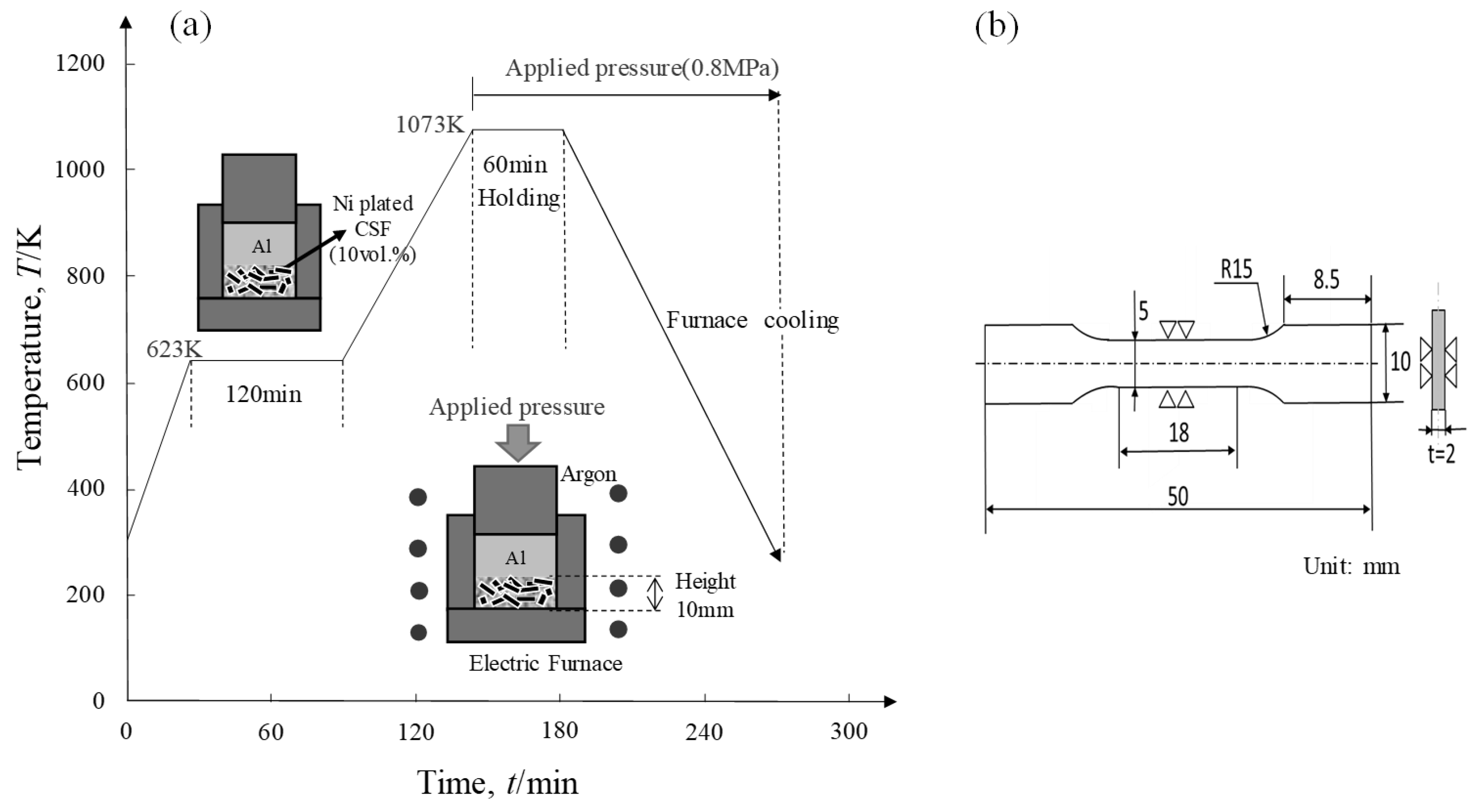
2. Materials and Manufacturing Methods

A1070 (purity, 99.7%), A356 alloy (6.5–7.5% Si—0.25-0.45% Mg) and A336 alloy (11–13% Si—0.8–1.5% Ni—0.5–1.5% Cu) are used as matrix for composites. The three types of Al-based matrix contain different kinds and contents of alloying elements. In order to infiltrate the molten Al into porous CF easily by the low-pressure infiltration (LPI) process, a good wettability between the CFs and molten Al is required. Electroless Ni plating was conducted on the CSFs for improving wettability [11]. As received CSFs and electroless nickel plated CSFs by 60 to 180 s plating time (pH of 6.5 and temperature of 313 K). The CSFs deposited by the electroless Ni plated were observed by EDS analysis (Genesis XM2).
Ni plated CSFs were put into a graphite mold of diameter 10 mm with adjustable height. To achieve a volume fraction of 10 vol.%, the height was adjusted to 10 mm. Al and Al alloy ingot were placed on the fibers, then the total mold was put into LPI equipment and heated up to the temperature of 623 K holding for 2 h. (in order to recrystallization of nickel [12]), and the temperature of the matrix was 1073 K. The infiltration pressure was 0.8 MPa [13]. Figure 1a shows the schematic illustration of the new fabrication process without preform manufacturing by low-pressure infiltration method. The microstructures of the Ni plated CSF and composites were observed using an Electron Probe Micro-Analyzer (EPMA, JXA-8900RL). The elemental analysis was carried out by energy-dispersive X-ray spectroscopy (EDS, S-5200 Energy Dispersive X-ray Analyzer, Hitachi, Japan). X-ray diffraction (XRD) was carried out with a Rigaku Smart Lab, Japan. Using Cu Kα radiation at 40 kV and 0.1 A, a scan speed of 2°/min was used in the range of 20–80°. Element analysis of surrounding carbon fibers was observed by Electron Probe Micro-Analyzer (EPMA, JXA-8900RL).
The hardness of the CSF/Al matrix composites was measured in a Vickers hardness tester. The values reported for Vickers hardness represented the average of ten separate measurements taken at randomly selected points using a load of 3 kg for 10 s. Tensile specimens with a thickness of 2 mm and a gauge length of 18 mm (Figure 1b) were cut from the composites in accordance with ASTM test method E8M-11. Tensile tests were carried out using a precision universal testing machine (AG-50KNX STD, SHIMADZU Inc., Kyoto, Japan) with a strain rate of 0.5 mm/min, the sampling time of 1 s at room temperature. The strain gauge (YEFLA-2, t = Tokyo Measuring Instruments Lab) was used for strain analysis. Thermal conductivity of CSF/Al matrix composites was measured by laser flash method thermal constants measuring system (TC-9000H, ULVAC-RIKO Inc., Yokohama, Japan) at the room temperature in air. The specimen size of CF/Al composites was ø 10 × 1.5 h. Thermal conductivity was evaluated according to ASTM E 1461-01.

3. Results

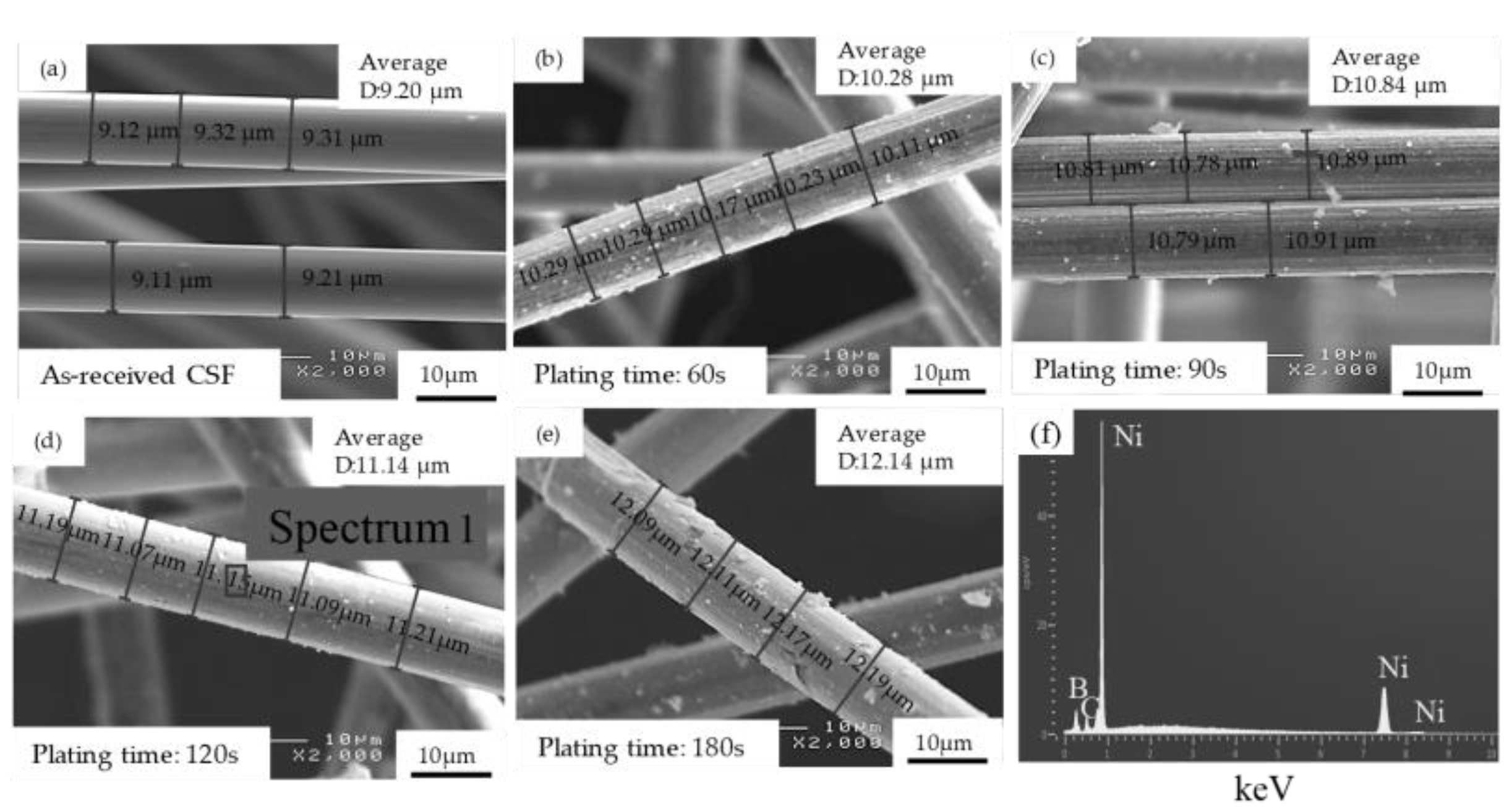
3.1. Thickness of Ni Plated CSFs by Plating Time

Figure 2 shows SEM images of as-received CSFs and electroless nickel-plated CSFs by 60 to 180 s plating time (pH of 6.5 and temperature of 313 K). As-received CSF presented a clean and smooth surface in Figure 2a. In Figure 2b,c,e, CSFs were not uniformly plated with Ni layer. In Figure 2d, a perfect uniformly Ni-plated layer was obtained over the CSFs. In the case of CSFs plating for 120 s that the Ni particles on fiber surface grew gradually, met each other particles, and formed a uniform metallic layer by the process of “layer formation”, which provided uniform wettability, and protection over CSFs. Figure 2f shows that there was no oxygen or other atoms atomic peak which meant the surface of CSF (plating time, 120 s) was wholly even covered by nickel layer. Therefore, Ni plated CSFs (plating time, 120 s) were selected for fabrication composites. The diameters of Ni plated CSFs by different plating times; diameters were calculated by Image-Pro Plus 5.0, which were marked in the images. The volume fraction of electroless plated Ni to CSF, the density of Ni plated CSF and the Ni plated thickness are summarized in Table 1.

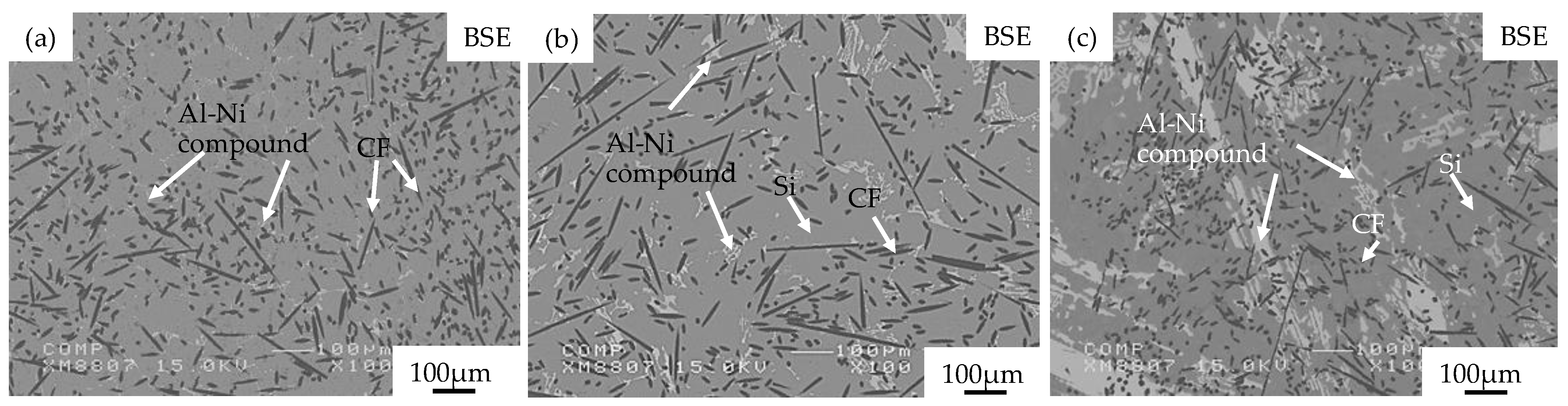
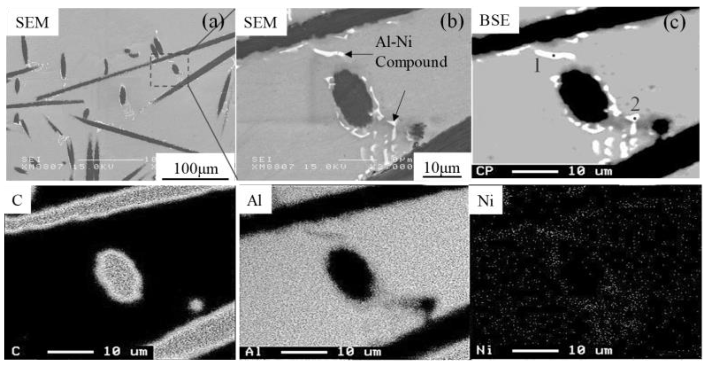
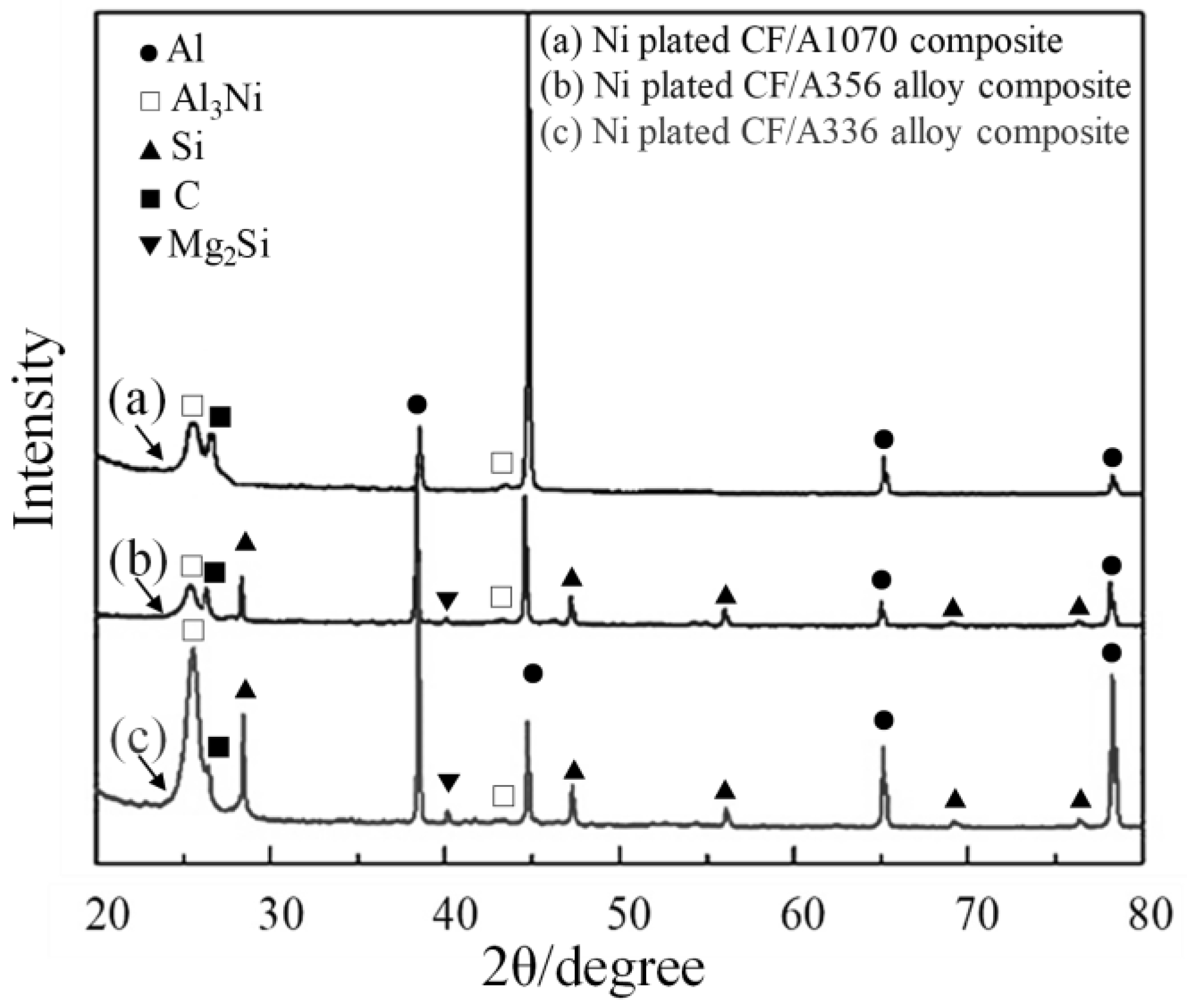
3.2. Microstructures of Ni plated CSF Reinforced Aluminum Matrix Composites

Figure 3 shows the microstructures on the surface of the Ni plated CSF/Al matrix composites fabricated under 0.8 MPa. The surface and cross-section of the composites have almost the same structure, so this paper shows only the surface structure of the composites. The volume fraction of carbon fiber is 10 vol.%. In Figure 3a–c, it is observed that the CSFs were randomly distributed in the composites, white phases were formed around CSFs and some were dispersed in the matrix. The white phases were supposed to be Al-Ni compounds that were generated by not only the Ni plated layers dissolving and reacting with the Al matrix, but also the Ni element in the matrix promoted the formation of compounds. Therefore, the content of the Al-Ni compound in Ni plated CSF/A336 alloy composites were much higher than the other two composites due to a higher amount of Ni element of A336 alloy. Si phases were observed in Figure 3b,c due to the existence of Si elements in A356 and A336 alloys. Table 2 shows the image analysis of the volume fraction of CSFs, Al-Ni compounds and Si phases of the Ni plated CSF/Al and Al alloy matrix composites fabricated under 0.8 MPa. Ni plated CSF/1070 and A356 alloy composites exhibited 3.6 vol.% of Al-Ni compounds, Ni plated CSF/A336 alloy composite exhibited 8.4 vol.% of Al-Ni compounds. The amount of Si phases in A356 and A336 alloys composites was about 8.0 vol.% and 15.0 vol.%, respectively, which was caused by 7 mass% and 12 mass% Si content in A356 and A336 alloys.
Figure 4 shows the SEM images and pore size of the Ni plated CSF/Al and Al alloy matrix composites fabricated 0.8 MPa. It can be found that there existed some imperfect infiltration regions (defects) such as pores between the CF/CF and CF/matrix in all composites. It is supposed that the molten Al preferentially infiltrated a largely spaced region of the adjacent CSFs. At the same time, the narrow space between the CSFs was difficult to infiltrate because of the existence of capillary resistance. Meanwhile, the fluidity of metals also had a great effect on infiltration. At the condition of 0.8 MPa, some large-size pores were observed in Figure 4a in the region of CF/CF (2.3 μm) and CF/matrix (1.9 μm); because there is no alloying element in 1070 Al lead to a poor metal fluidity, the CSFs cannot be fully infiltrated result in large pores between the CF/CF and CF/matrix. Figure 4b,c showed an apparent decrease in the size of pores than 1070 composite due to the existence of Si element in Al alloys, which could increase the metal fluidity. Especially, Figure 4c possessed the smallest pore size compared to Figure 4a,b due to the highest amount of Si element (13 mass%) of A336 alloy. Compared with Figure 4a,b, Figure 4c showed an obvious decrease of pore size in the region between the CF/CF and CF/matrix of each composite by applied infiltration pressure of 0.8 MPa.
Element area mapping by EMPA and EDS analysis were conducted to Ni plated CSF/A1070 composite as shown in Figure 5 and Table 3. In Figure 5, Intermetallic compounds (IMC) were identified around CSF by the reaction of Ni plating and aluminum. The EDX analysis data of IMC showed the ratio of Al to Ni was 3:1, which confirmed the Al-Ni compound was Al3Ni phase (Table.3). The Al3Ni phase was generated as the following process: the infiltration temperature was 1073 K, from the Ni plated layer on the surface of CSFs was in contact with molten aluminum and reacted with aluminum directly. It was observed that the Al3Ni phases were separated from the surface of CSFs in Figure 5, in light of the densities of the Ni and Al3Ni, i.e., 8.9 and 4.0 kg/m3, the formation of Al3Ni was thought to be an expansion reaction and finally, the fine Al3Ni phases were dispersed into the matrix, which was separated from the CSFs surface.
Figure 6a–c depicts the X-ray diffraction results of electroless Ni plated CSF/Al matrix composites. The detected crystals are only Al, C, Al3Ni, Mg2Si, and Si. It is worth noting that no peaks for Al4C3 were detected in all electroless Ni plated CSF/Al matrix composites which indicated that the Ni plated layer acted as a barrier layer to effectively prevent the matrix from chemically reacting with the CSFs to cause damage to the strength of the fibers. The peak of Al3Ni, Mg2Si, and Si phase in Figure 6c is higher than that of other composites, which meant a higher content of IMCs and precipitate in electroless Ni plated CSF/A336 alloy composite.

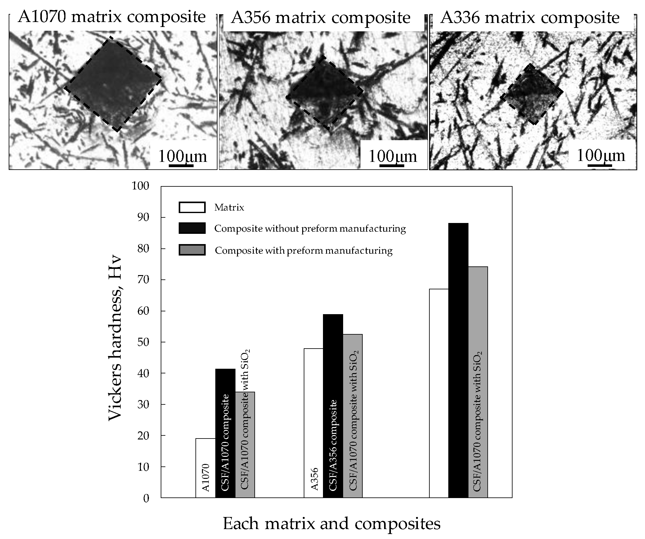
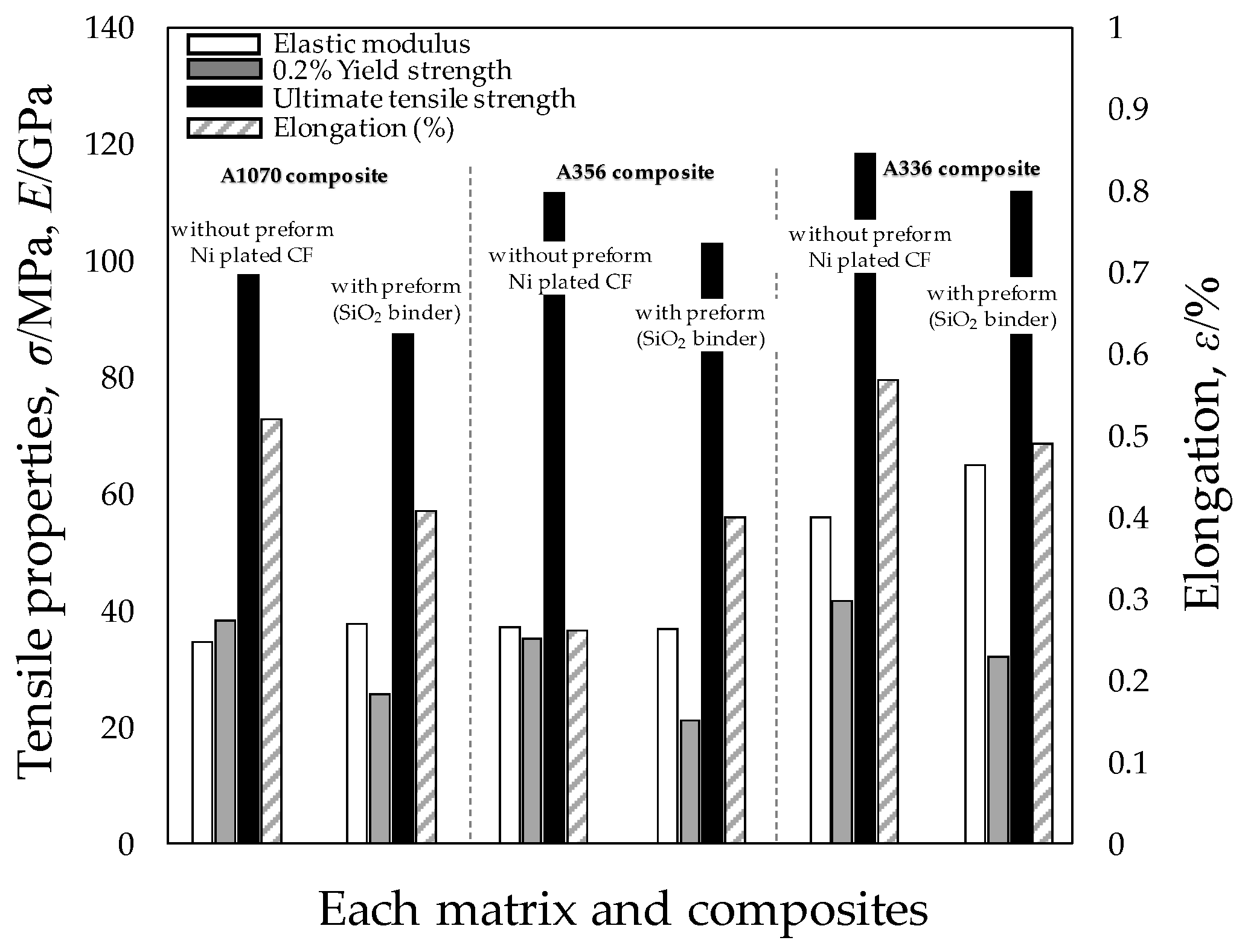
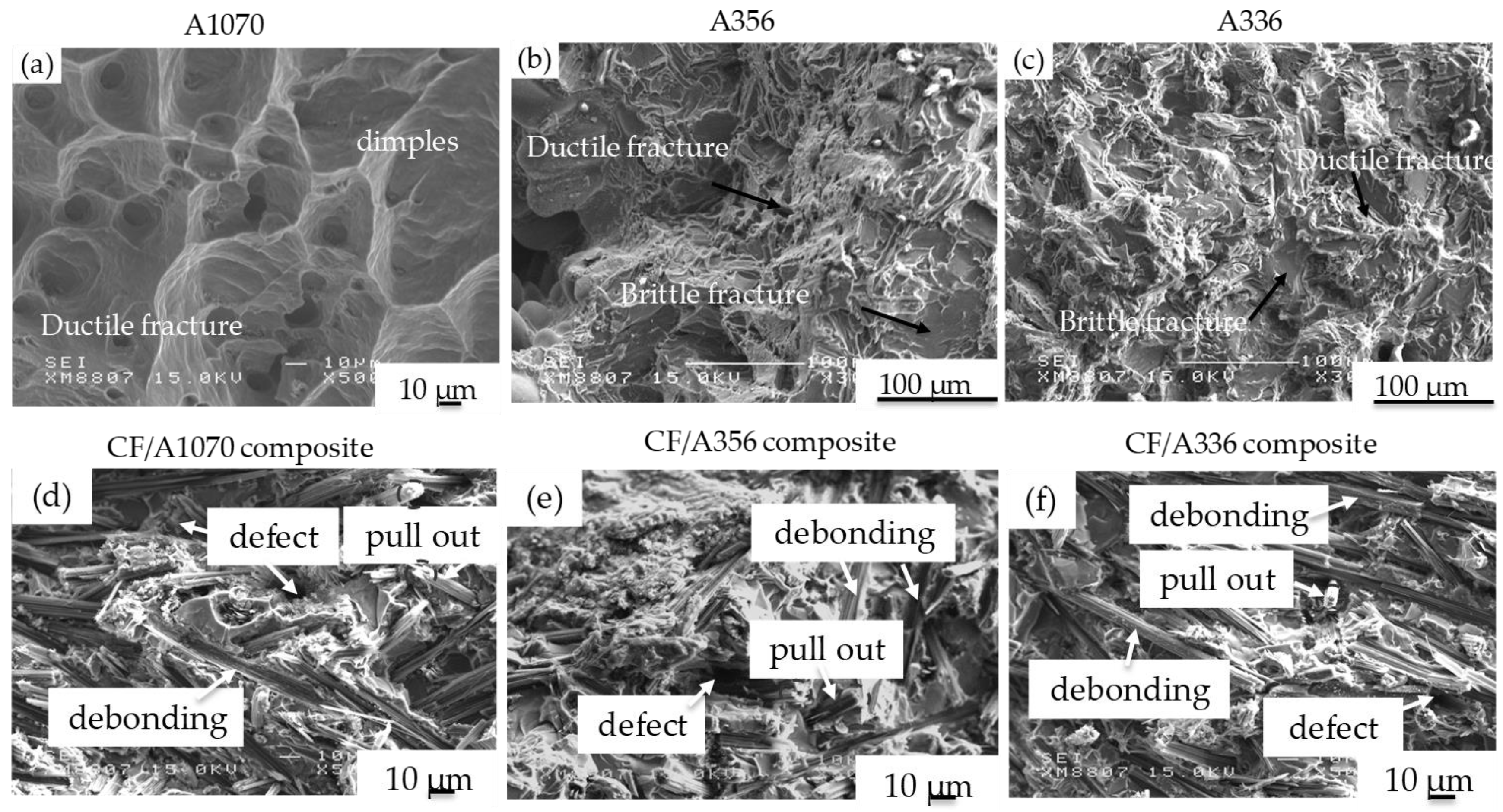
3.3. Hardness and Tensile Strength of Each Matrix and CSF Reinforced Al and Al Alloy Matrix Composites

Figure 7 shows the Vickers hardness of each matrix and Ni plated CSF/Al and Al alloy matrix composites fabricated without preform manufacturing. In addition, the properties of the CSF/Al and Al alloy matrix composites produced by fabricating a preform (SiO2 binder) used in the conventional composite material were compared. Vickers hardness of Ni plated CSF/A1070, A356 alloy, and A336 alloy composites were 41.3 Hv, 58.8 Hv, and 88.4 Hv, respectively, which presented an improvement of 116.2%, 23.1%, and 31.4% as compared to matrix. The introduction of CSF, generation of Al3Ni phase, and the solid solution strengthening caused by Si phase precipitation in Al alloys composites contributed to the increase of hardness. A336 alloy possessed the highest content of Si (12 mass%) and Ni (1.5 mass%) elements, therefore, the highest content of IMCs and precipitate in Ni plated CSF/A336 alloy composite enables it to possess the highest hardness. In addition, the hardness of the Ni plated CSF/Al and Al alloy matrix composite was slightly increased compared to the CSF/Al and Al alloy matrix composite fabricated by preform (SiO2 binder). The measurement of hardness is the global hardness of the composites. In measuring the hardness of the three types of composite, the hardness indentations photograph shows that they were measured including carbon fiber and base material.
Figure 8 shows the tensile properties of each matrix and Ni plated CSF/Al and Al alloy matrix composites fabricated without preform manufacturing. In addition, the properties of the CSF/Al and Al alloy matrix composites produced by fabricating a preform (SiO2 binder) used in the conventional composite material were compared. The 0.2% yield strength and ultimate tensile strength (UTS) increased by changing the matrix from A1070 to A336 alloy, and the CSF/A336 alloy composite possessed the highest UTS than the other two kinds of composites due to the highest content of Si precipitate and Al3Ni compounds. As for the comparison of Ni plated CSF/Al alloys composites and CSF/Al and Al alloy matrix composite fabricated by preform (SiO2 binder), the 0.2% yield strength and UTS of Ni plated CSF/A356 alloy composite was slightly increased compared to the CSF/Al and Al alloy matrix composite fabricated by preform (SiO2 binder). However, there was no trend in elastic modulus or elongation. The manufactured composites without a preform show better tensile strength characteristics than a composite made by the conventional manufacturing method with preform. However, it can be seen that the elongation of the composites is much weaker than that of the general aluminum. This is due to the weak interfacial strength between the CF and aluminum. Figure 9 shows tensile fracture surfaces of each matrix and Ni plated CSF/Al matrix composites: (a), (d) A1070 and composite, (b), (e) A356 alloy and composite, (e), (f) A336 alloy and composite. The fracture surface of A1070 shows the presence of many dimples. However, for the A356 and A336 alloys, the main fracture mechanism was a ductile fracture, while the brittle fracture occurred at the place of Si and IMC, a lot of cleavage stages were observed. The fracture mechanism of Ni plated CSF/A1070 composite was changed to brittle fracture, and lots of large size pores were also observed as shown in Figure 9d. The A1070 matrix possesses no alloying elements with relatively limited tensile properties. The increased UTS of the A1070 composite than A1070 matrix was attributed to the presence of CSFs and the formation of Al3Ni in composites, which could increase the resistance to crack propagation, as a result of enhancement of the tensile property of composite. Figure 9d shows fibers pull out and debonding generated by the high number of pores between the CSF/CSF and CSF/matrix. Therefore, the enhancement effect on the tensile property was weakened accordingly. The fracture mechanism of Ni plated CSF/Al alloys composites were brittle fracture, while cleavage stages were seldom observed by the addition of CSFs as shown in Figure 9e,f. Pores with reduced size were observed compared to A1070 composites. However, lots of fibers debonding and fibers pull-out were observed at the fracture surfaces of CSF/Al alloys composites. Al alloys matrix possess a high content of alloying elements which fulfill their high tensile strength. The pores in composites increased the possibility of minute cracks generation, also the interface of CSFs and Al matrix shows poor bonding characteristics, cracks propagated along with the interface that rarely propagated through the fibers, which inevitably led to the failure of the material with low strength than Al alloys matrix.

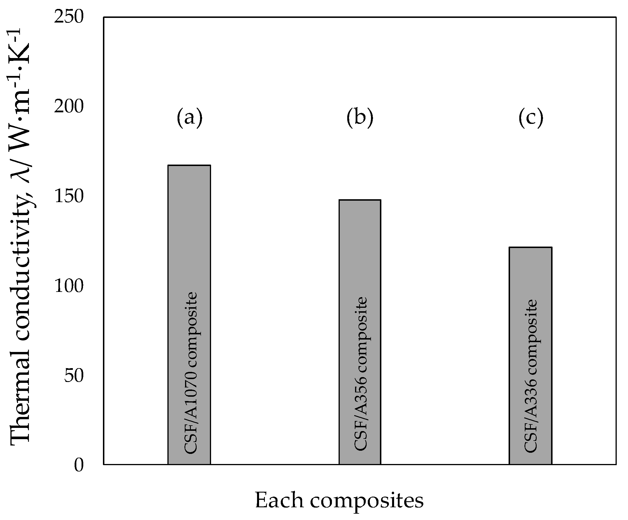
3.4. Thermal Conductivity of CSF Reinforced Al and Al Alloy Matrix Composites

Figure 10 shows the thermal conductivity of Ni plated CSF/Al and Al alloy composites. TC of Ni plated CSF/A1070 composite was 167.1 W·m−1·K−1. However, the TC of Ni plated CSF/A356 alloy and A336 alloy composites were 147.6 and 121. 5 W·m−1·K−1 receptivity. Especially, Ni plated CSF/A336 alloy composite presented the lowest TC compared with other composites. Ni plated CSF/A336 alloy composite possessed the highest content of Al3Ni compounds than other composites. The highest amount of Al3Ni compounds was by not only the Ni plated layer but also the high content of Ni (1.5 mass%) in the A336 alloy matrix. The Al3Ni compound with low TC to be approximately 35 W·m−1·K−1 acted a role of the thermal resistance to the heat flow and leads to degradation of the thermal properties of composites [14]. In addition, the precipitate was also a factor that weakens the TC of composites. A336 alloy possessed the highest content of Si than A356 alloy, resulting in a higher degree of Si phase precipitation in Ni plated CSF/A336 alloy composite. The higher degree of supersaturation of the Si phase results in severe distortion of the crystal lattice and provides additional interfacial resistance, which would further obstruct effective thermal conduction through the matrix. As a result, the Ni plated CSF/A336 alloy composite exhibited the lowest TC.

4. Conclusions

A new fabrication process without preform manufacturing has been developed for CSF/Al and Al alloy matrix composites. And their mechanical and thermal properties were evaluated. Pores of the Ni plated CSF/Al and Al alloy matrix composites fabricated 0.8 MPa. It can be found that there existed some imperfect infiltration regions such as infiltration pores between the CF/CF and CF/matrix in all composites. However, pore size (1 µm) in the region between the CF/CF and CF/matrix to used A336 matrix. Vickers hardness of Ni plated CSF/A1070, A356 alloy, and A336 alloy composites were higher as compared to matrix. Al3Ni by electroless Ni plating and the solid solution strengthening caused by Si phase precipitation in Al alloys contributed to the increase of hardness. A336 alloy possessed the highest content of Si (12 mass%) and Ni (1.5 mass%) elements; therefore, the highest content of IMCs and precipitate in Ni plated CSF/A336 alloy composite enables it to possess the highest hardness. Ultimate tensile strength (UTS) increased by changing the matrix from A1070 to A336 alloy, and the CSF/A336 alloy composite possessed the highest UTS than the other two kinds of composites due to the highest content of Si precipitate and Al3Ni compounds. However, the tensile strength of Ni plated CSF/A336 alloy composite was decreased than the A336 alloy matrix because of the large size of IMCs. Furthermore, the 0.2% yield strength and UTS of Ni plated CSF/A356 alloy composite was slightly increased compared to the CSF/Al and Al alloy matrix composite fabricated by preform (SiO2 binder). The thermal conductivity of Ni plated CSF/A1070 composite has higher value (167.1 W·m−1·K−1) because of small contains the IMCs.

Author Contributions

Y.C. and Z.X. conceived the idea and designed experiments. X.M. carried out the experiments and data analysis. They also contributed to the manuscript writing and Y.C. prepare the response to the reviewer’s comments. Z.X. checked the data and discussed it. All authors have read and agreed to the published version of the manuscript.

Funding

This study was supported by JSPS KAKENHI Grant Number 18K03839.

Conflicts of Interest

The authors declare no competing interests.

References

  1. Molina, J.; Narciso, J.; Weber, L.; Mortensen, A.; Louis, E. Thermal conductivity of Al-SiC composites with monomodal and bimodal particle size distribution. Mater. Sci. Eng. A 2008, 480, 483–488. [Google Scholar] [CrossRef]
  2. Euh, K.J.; Kang, S.B. Effect of rolling on the thermon-physical properteis of SiCp/Al composites fabricated by plasma spraying. Mater. Sci. Eng. A 2005, 395, 47–52. [Google Scholar] [CrossRef]
  3. Ames, W.; Alpas, A.T. Wear mechanisms in hybrid composites of graphite-20 Pct SiC in A 356 alumium alloy. Metall. Mater. Trans. A 1995, 26, 85–98. [Google Scholar] [CrossRef]
  4. Tjong, S.C.; Lau, K.C.; Wu, S.Q. Wear of al-badsed hybird composites contating BN and SiC particulates. Metall. Mater. Trans. A 1999, 30, 2551–2555. [Google Scholar] [CrossRef]
  5. Laffont, L.; Monthioux, M.; Serin, V. Plasmon as a tool for in situ evaluation of physical properties for carbon materials. Carbon 2002, 40, 767–780. [Google Scholar] [CrossRef]
  6. Chang, K.C.; Matsugi, K.; Sasaki, G.; Yanagisawa, O. Infiluence of fiber surface structure on interface reaction between carbon and alumminum. J. Jpn. Institure Met. 2005, 48, 205–209. [Google Scholar]
  7. Choi, Y.B.; Sasaki, G.; Matsugi, K.; Yanagisawa, O. Mater. Effect of ultrasonic vibration on infiltration of nickel porous preform with molten aluminum alloy. Mater. Trans. 2005, 46, 2156–2158. [Google Scholar] [CrossRef]
  8. Choi, Y.B.; Sasaki, G.; Matsugi, K.; Sorida, N.; Kondoh, S.; Fujii, T.; Yanagisawa, O. Simulation of infiltration of molten alloy to porous prefrom using low pressure. Jpn. Soc. Mecahnical Eng. A 2006, 49, 20–24. [Google Scholar]
  9. Choi, Y.B.; Matsugi, K.; Sasaki, G.; Arita, K.; Yanagisawa, O. Analysis of manufacturing process for metal fiver reinforced aluminum alloy composite fabricated by low pressure casting. Mater. Trans. 2006, 47, 1227–1231. [Google Scholar] [CrossRef] [Green Version]
  10. Bakshi, S.R.; Keshri, A.K.; Singh, V.; Seal, S.; Agarwal, A. Inerface in carbon nanotube reinforced aluminum silicon composites: Thermodynamic analysis and experimental verification. J. Alloys Compouds 2009, 481, 207–213. [Google Scholar] [CrossRef]
  11. Cui, G.F.; Li, N.; Li, D.; Zheng, J.; Wu, Q.L. The physical and electrochemical properties of eletroless deposited nickel-phosphorus black coating. Surf. Coat. Technol. 2006, 200, 6808–6814. [Google Scholar] [CrossRef]
  12. Ashassi-Sorkhabi, H.; Rafizadeh, S.H. Effect of coating time and heat treatment on structures and corrosion characteristics of electroless Ni-P alloy deposits. Surf. Coat. Technol. 2004, 176, 318–326. [Google Scholar] [CrossRef]
  13. Meng, X.; Choi, Y.B.; Matsugi, K.; Liu, W. Development of carbon short fiber reinforced al based composite without preform manufacturing. Mater. Trans. 2020, 61, 1041–1044. [Google Scholar] [CrossRef]
  14. Terada, Y.; Ohkubo, K.; Mohri, T.; Suzuki, T. Thermal conductivity. Metall. Mater. Trans. A 2003, 34, 3167–3176. [Google Scholar] [CrossRef]
Figure 1. (a) Schematic illustration of the new fabrication process without preform manufacturing by low-pressure infiltration method and (b) shape and dimension of tensile specimens (unit: mm).
Jcs 05 00307 g001
Figure 2. SEM images of (a) as-received CSF, (b) Ni plated CSF (60 s), (c) Ni plated CSF (90 s), (d) Ni plated CSF (120 s), (e) Ni plated CSF (180 s) and (f) EDS data of Ni plated CSF (120 s).
Jcs 05 00307 g002
Figure 3. Microstructures of composites: (a) Ni plated CSF/A1070 composite, (b) Ni plated CSF/A356 alloy composite, and (c) Ni plated CSF/A336 alloy composite.
Jcs 05 00307 g003
Figure 4. SEM images of pores of composites (0.8 MPa): (a) Ni plated CSF/A1070 composite, (b) Ni plated CSF/A356 alloy composite, and (c) Ni plated CSF/A336 alloy composite.
Jcs 05 00307 g004
Figure 5. Element mapping analysis of surrounding carbon fiber and Al matrix in Ni plated CSF/A1070 composite.
Jcs 05 00307 g005
Figure 6. Results of X-ray diffraction spectra of composites: (a) Ni plated CSF/A1070 composite, (b) Ni plated CSF/A356 alloy composite, and (c) Ni plated CSF/A336 alloy composite.
Jcs 05 00307 g006
Figure 7. Vickers hardness of Ni plated CSF/Al and Al alloy matrix composites compared to composite of preform manufacturing with SiO2 binder.
Jcs 05 00307 g007
Figure 8. Tensile properties of Ni plated CSF/Al and Al alloy matrix composites compared to composite of preform manufacturing with SiO2 binder.
Jcs 05 00307 g008
Figure 9. Tensile fracture surfaces of each matrix and Ni plated CSF/Al matrix composites: (a,d) A1070 and composite, (b,e) A356 alloy and composite, (c,f) A336 alloy and composite.
Jcs 05 00307 g009
Figure 10. Thermal conductivity of Ni plated CSF/Al matrix composites: (a) Ni plated CSF/A1070 composite, (b) Ni plated CSF/A356 alloy composite and (c) Ni plated CSF/A336 alloy composite.
Jcs 05 00307 g010
Table 1. Results of Electroless Ni plated CFs with different plating times.
Plating Time
(s)
Ni/CSF
(Vol.%)
Ni/CSF
(Wt.%)
Density of Ni Plated
CSF (g/cm3)
Ni Plated Thickness
(μm)
0
602.811.52.37 0.54 0.02 + 0.05
904.317.52.47 0.82 0.13 + 0.03
1205.322.52.53 0.97 0.02 + 0.11
1807.932.02.70 1.45 0.01 + 0.12
Table 2. Volume fraction of CSFs, Al-Ni compounds and Si phases in Ni plated CSF/Al matrix composites fabricated under 0.8 MPa.
CSF/Al1070
Composite
CSF/A356
Composite
CSF/A336
Composite
CSFs
Vol.%
Al-Ni
Compounds
Vol.%
CSFs
vol.%
Al-Ni
Compounds
Vol.%
Si
Vol.%
CSFs
vol.%
Al-Ni
Compounds
Vol.%
Si
Vol.%
13.73.613.03.68.013.58.415.2
Table 3. Point analysis of Ni plated CSF/A1070 composite by EDS in Figure 5c.
PositionComposition (at%)Al:NiAl-Ni Phase
AlNi
172.4523.3603:01Al3Ni
274.8622.58
Publisher’s Note: MDPI stays neutral with regard to jurisdictional claims in published maps and institutional affiliations.

