Article

Dual In-Situ Water Diffusion Monitoring of GFRPs based on Optical Fibres and CNTs

1
Politecnico di Torino, C.so Duca degli Abruzzi 24, 10129 Torino, Italy
2
School of Engineering and Materials Science, Queen Mary University of London, Mile End Road, London E1 4NS, UK
3
La Sapienza, Universita’ di Roma, Via Eudossiana 18, 00184 Roma, Italy
4
Nanoforce, Queen Mary University of London, Joseph Priestley Building, Mile End Road, London E1 4NS, UK
*
Author to whom correspondence should be addressed.
J. Compos. Sci. 2020, 4(3), 97; https://doi.org/10.3390/jcs4030097
Submission received: 3 June 2020 / Revised: 17 July 2020 / Accepted: 19 July 2020 / Published: 23 July 2020
(This article belongs to the Special Issue Recent Advances in Carbon Nanotube Composites)

Abstract

:
Glass Fibre Reinforced Polymer (GRFP) composites are increasingly being used as new materials for civil and petrochemical engineering infrastructures, owing to the combination of relatively high specific strength and stiffness and cost-competitiveness over traditional materials. However, practical concerns remain on the environmental stability of these materials in harsh environments. For instance, diffusion of salty water through the composites can trigger degradation and ageing. For this reason, a continuous monitoring of the integrity of GFRP composites is required. GRFPs health monitoring solutions, being non-destructive, in-situ, real-time, highly reliable and remotely controllable, are as desirable as challenging. Herein we develop and compare two methods for real-time monitoring of GRFP: one based on the electrical sensing signals of percolated carbon nanotubes (CNTs) networks and the other on optical fibre sensors (OFSs). As a proof-of-concept of dual sensory system, both sensors were used in combination to detect the diffusion of water through the composite. Measurements demonstrated that both CNTs and OFSs were able to detect water diffusion through the epoxy matrix successfully, with an on-off sensing behaviour. OFSs exhibit some advantages since they do not require electrical supply as required in hazardous environments and are more suitable for remote operation, which make them attractive for new developments in harsh-environment sensing. On the other hand, CNTs can be easily embedded in the composite without compromising its performance (e.g., mechanical properties) and are easily interrogated by measurement of electrical conductance, therefore could be used as spot sensors in the most failure-prone sections of GFRP components. This study opens up the possibility for an early detection of composites degradation, which could prevent failures in GFRP structures such as pipelines and storage tanks used in the oil and gas industry.

1. Introduction

Glass Fibre Reinforced Plastics (GFRPs) present very attractive properties such as high specific strength and stiffness, design flexibility and cost-competitiveness [1]. These features make them very attractive and suitable for high performance applications in oil and gas, marine and construction engineering [2]. However, there is major demand to monitor, if not to understand and predict, the ageing behaviour of GFRPs when they are exposed to chemicals such as the ones present in an oil or gas field, [3,4,5].
To ensure structural integrity and safety, composite structures used in civil infrastructures have to be equipped with a sensing system able to detect in real time the effects produced by various stimuli, for instance, by stress, strain, temperature and ageing [6]. Among various technologies, optical fibre sensors (OFSs) exhibit interesting features since they are not affected by magnetic fields and are safer to use as they do not require electric supply [7,8]. Optical Fibre Bragg Gratings (FBGs) represent a standard in the OFS market. The introduction of one or more of these optical sensors allows the detection of various physical or chemicals perturbations in the composite [9]. However, FBGs are expensive and, in some cases, the temperature sensitivity represents a spurious effect that has to be compensated for [10]. The development of new, low-cost sensors based on optical fibres or alternative technologies is becoming increasingly attractive for oil and gas companies [7].
Owing to their high electrical conductivity combined with high mechanical and thermal properties and large aspect ratios, carbon nanotubes (CNTs) have recently been investigated as a nanofiller in several structural composites [11,12], and in particular for sensing purposes [13]. Even small amounts of CNTs (well below 1 wt. %) can form percolated conductive networks, which can be used to detect a number of different stimuli [12,14,15,16]. However, the presence of CNTs can negatively affect the rheology, processing and curing of thermoset resins [17]. Moreover, the delivery of CNTs into a structural composite, by the most common manufacturing processes, is challenging as CNTs are filtered by the reinforcement fibre fabrics during, for instance, infusion [18]. Alternative methods have recently been proposed to overcome such manufacturing issues such as spraying directly CNTs in glass fibres [19,20].
This paper aims at comparing two sensing technologies (OFS and CNTs) and exploring the possibility of combining them for potential online structural health monitoring applications. As an experimental proof-of-concept, the sensors are directly embedded within a GFRP composite. The OFSs, based on evanescent wave sensing, are embedded in the GFRP composite and monitored as described in a recent work by the same authors [21]. The CNTs sensors [19], are realized by addition of CNTs, either mixed into the epoxy matrix or spray-coated onto the GFRP plies. Results on sensing of water diffusion tests are presented herein.

2. Materials and Methods

2.1. Epoxy and GFRP Containing CNTs Samples Fabrication

Multiwalled CNTs (NC7000 Nanocyl, Sambreville, Belgium) were manually mixed to the epoxy resin (Ampreg 26, purchased from Gurit, Wattwil, Switzerland). Afterwards, the formulation was thoroughly mixed using a Three Roll Mill (TRM) instrument (80E EXAKT Advanced Technologies, Norderstedt, Germany) [22].
Different CNT filler contents were used to examine the electrical percolation threshold (0.00, 0.01, 0.25, 0.05, 0.75, 1.00 and 1.50 wt. %). The samples containing CNTs were degassed for 1 h under the vacuum pressure of −1 bar, before casting [23] into a silicone mould. Strips of aluminium foil, of dimension of 80 mm length, 3 mm width and 0.5 mm thickness, used as electrodes, had been positioned inside of the mould before casting. The epoxy resin was cured following the curing conditions previously defined [21].
The percolation threshold of CNTs was calculated by the classical percolation theory equation, describing the conductivity change with filler content (Equation (1)) [18]:
σ = σ 0 ( φ φ c ) t
where σ is the conductivity of the resin containing CNTs, σ 0 is the scaling factor, φ is the filler content, φ c is the percolation threshold and t is a critical exponent which is expected to depend on the conductive system dimensionality only.
Unsurprisingly, the viscosity of the epoxy increased with CNT content, as qualitatively observed during the casting process. Moreover, the filler tends to agglomerate, making it more difficult to obtain a good dispersion at higher CNT contents. To overcome these problems, CNTs were directly deposited on the Advantex E-CR glass fibre fabric (Owens Corning, USA) [1,24]. A dispersion of 0.01 g of CNTs in 100 mL of methanol (MeOH), (purchased from Sigma Aldrich, Gillingham, UK), was ultrasonicated with 20 % of the maximum amplitude level for 15 min with 1s On and 1s OFF (for a total at 5000 J energy). After sonication, the suspension was sprayed with an airbrush on the glass fibre plies. The GFRP composites contained two plies; the two spray coated plies were assembled by positioning the spray coated side (0.50 wt. % of CNTs with respect to the GF ply mass) of each ply in contact with each other (one ply at 90 ° respect to the other ply) [19]. The so manufactured GFRP composite is referred to as GFRP05.
The epoxy nanocomposites containing 0.50 wt. % of CNTs and the GFRP05 samples were immersed into artificial sea water—prepared according to the ASTM D1141-93 procedure [25]—at 80 °C. The absorption curves were obtained from gravimetric measurements until saturation. The diffusion coefficients of the epoxy and GFRP samples were calculated by Equation (2).
D = π ( h 4 M ) 2 ( M 2 M 1 t 2 t 1 ) 2
where h is the sample thickness, M is the weight gain at saturation expressed in percentage; M 1 and M 2 are two points on the linear section of the weight gain curve expressed in percentage, while t 1 , t 2 are the corresponding time spots in s [4].
In order to evaluate any “edge effect”, and hence deviation from simple through-thickness unidimensional diffusion, Starink’s correction formula was used (Equation (3)) [26]:
f S S C = 1 + 0.54 h w + 0.54 h l + 0.3 h 2 w l
where h is the height, w is the with and l the length of the sample.
More elaborated models have also been considered, like the anisotropic diffusivities approximation proposed by Gagani et al. [27], which has not been included as it did not return any significant change in the estimated diffusion times.

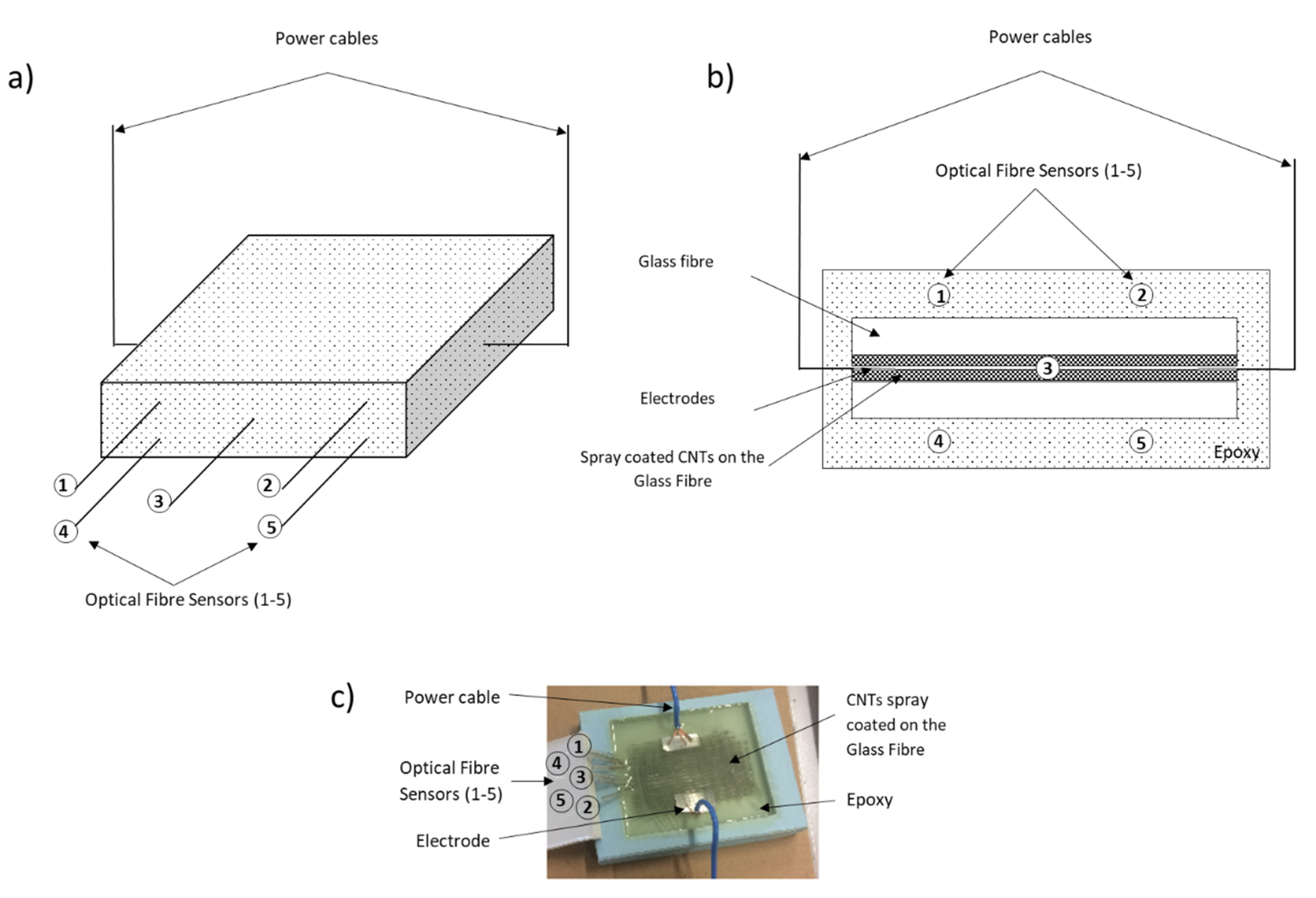
2.2. GFRP Samples Containing Spray Coated CNTs with Embedded OFSs Fabrication

The OFSs were fabricated by etching a multimode commercial optical fibre (GIF625 Silica multimode fibre, Thorlabs, Ely, UK). A section of 2 metres long optical fibre was cut. Then 15 cm of the polymer coating of one optical fibre end was mechanically stripped. The stripped optical fibre section of 125 μm was immersed in hydrofluoric acid (HF) to etch the cladding of the fibre until a diameter of ~ 60 μm was reached, in order to expose the core to surrounding environment. Silver coating was deposited on the extreme fibre tip (previously cut using a cleaver to obtain a total etched length of 8 cm) using the Tollens’ reagent [28]. The thickness of the silver deposited was ~ 5 μm. Having the silver at the end of the tip, the transmitted light is reflected and the sensors can perfectly work in a single-ended sensor [21,29]. The OFSs were embedded into epoxy and GFRP samples during the casting, as detailed in the following sections.
The hybrid GFRP composite (H-GFRP) consisted of five optical fibre sensors and two GF plies spray coated with 0.50 wt. % CNTs. Figure 1 shows a schematic and an optical picture of the H-GFRP sample, where four OFSs are placed on the outer parts and the one in the middle of the plies containing the CNTs.
The H-GFRP was fabricated using a custom mould with inner dimensions of 50 mm × 80 mm × 110 mm. It was possible to calculate approximately the water diffusion distance, from the epoxy surface to fibres 1, 2, 4 and 5 in Figure 2, with Fick’s law, (Equation (4)), [30] and using the water diffusion coefficient in the epoxy measured in [21,30].
d = 2 D d t
where d is the distance of the water diffusion, t is the time corresponding to the signal drop of the sensor and D is the diffusion constant.

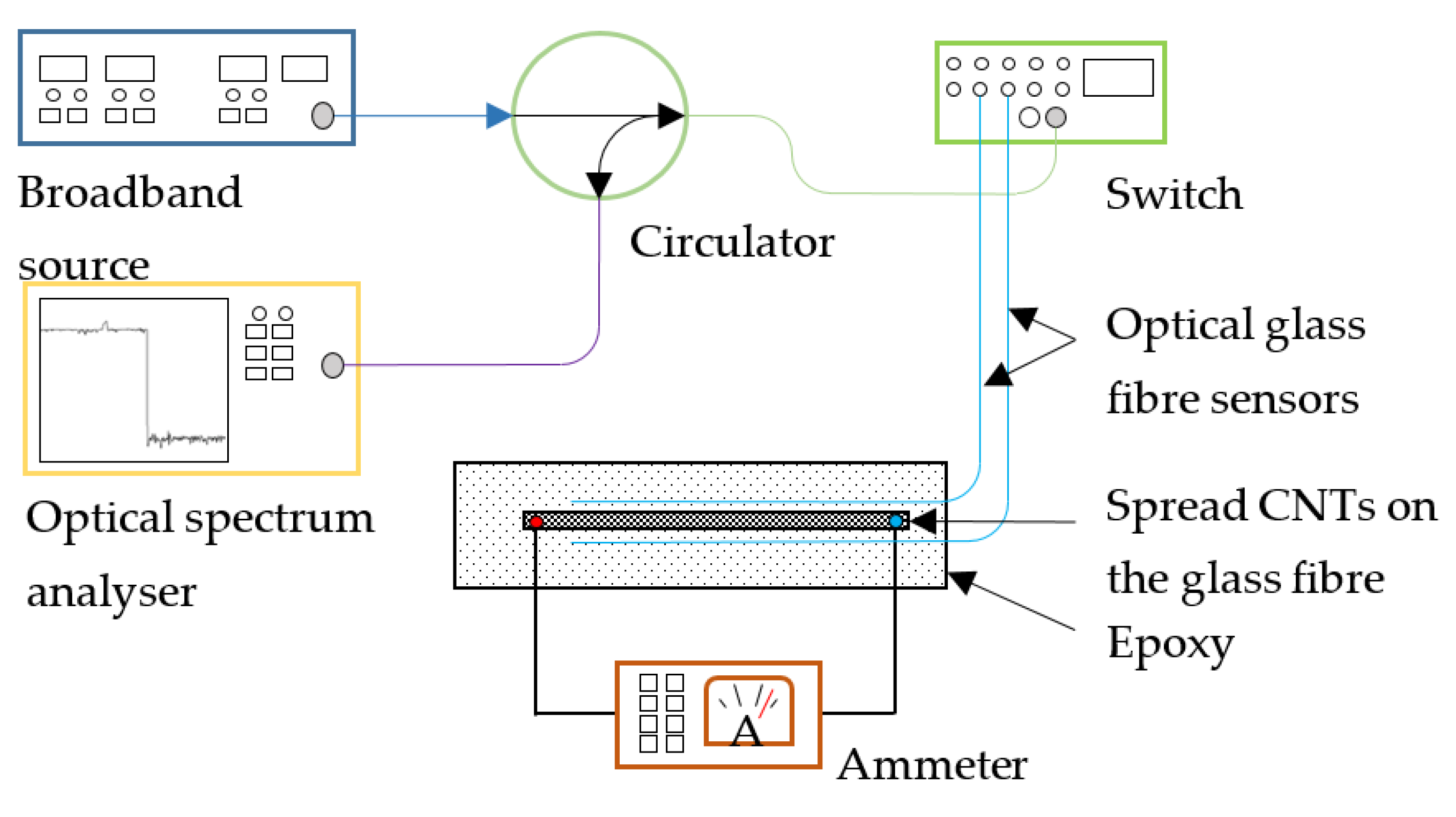
2.3. Optical Fibre Sensors Fabrication and the Interrogation Setup

The OFSs were interrogated with a broadband source (Photonetics 3626BT, Victoria, Australia) in the range 1500–1600 nm with a total power of 25 mW. The optical signal was computer-controlled with a fibre optics switch (JDS Uniphase 2x16 SB series, Colorado Springs, CO, USA) using a LabVIEW custom-developed program. The sensors were connected to the switch by movable connectors (Thorlabs BFT-1, Thorlabs, Ely, UK). The reflected signal, containing the sensing information, was separated from the source signal with an optical circulator and then displayed to an optical spectrum analyser (Avantes AvaSpec-NIR256-1.7, Avantes, Apeldoorn, The Netherlands) (Figure 2). The experiments were carried out by continuous recording spectra every 30 minutes. On the other hand, a two-probes ammeter (Keithley SMU 2400, Keithley Instruments/Tektronix, Cleveland, OH, USA) was used for the electrical resistance measurements of the CNTs.

3. Results and Discussion

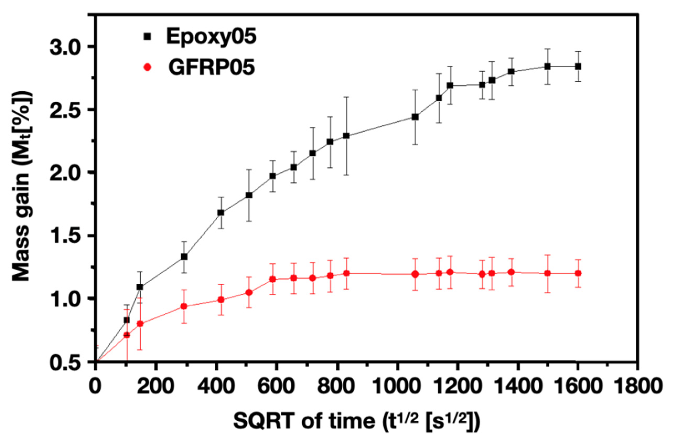
3.1. Evaluation of the Diffusion Coefficients

Figure 3 reports the water uptake (i.e., mass gain) curves as a function of time for epoxy nanocomposite samples containing 0.5 wt. % of CNTs (Epoxy05), and GFRP samples containing 0.5 wt. % of CNTs spray coated on the glass fibre plies (GFRP05). The diffusion coefficients were calculated using Equation (2). The presence of CNTs reduced the diffusion rates ( 5.4 ± 0.3 × 10 12 m 2 / s and 4.0 ± 0.1 × 10 12 m 2 / s , respectively for Epoxy05 and GFRP05) compared to pure epoxy and GFRP samples ( 8.8 ± 0.4 × 10 12 m 2 / s [21] and 4.9 ± 0.1 × 10 12 m 2 / s [30], respectively). The decrease in diffusion rate is smaller in the case of GFRPs samples than epoxy samples, as expected because the CNTs are locally deposited instead of dispersed through the matrix, as well as the presence of the glass fibre phase. These results are in agreement with the work of Prolongo et al. [31], reporting a significant decrease of the overall water diffusion in samples containing CNTs, explained by the increased hydrophobicity.
After applying the edge effect correction (Equation (3)), the new diffusion coefficients are slightly lower, with values for neat epoxy and GFRP samples of 8.5 ± 0.4 × 10 12 m 2 / s and 4.7 ± 0.1 × 10 12 m 2 / s , respectively. These are in agreement with the values reported by Cavasin et al. [32].

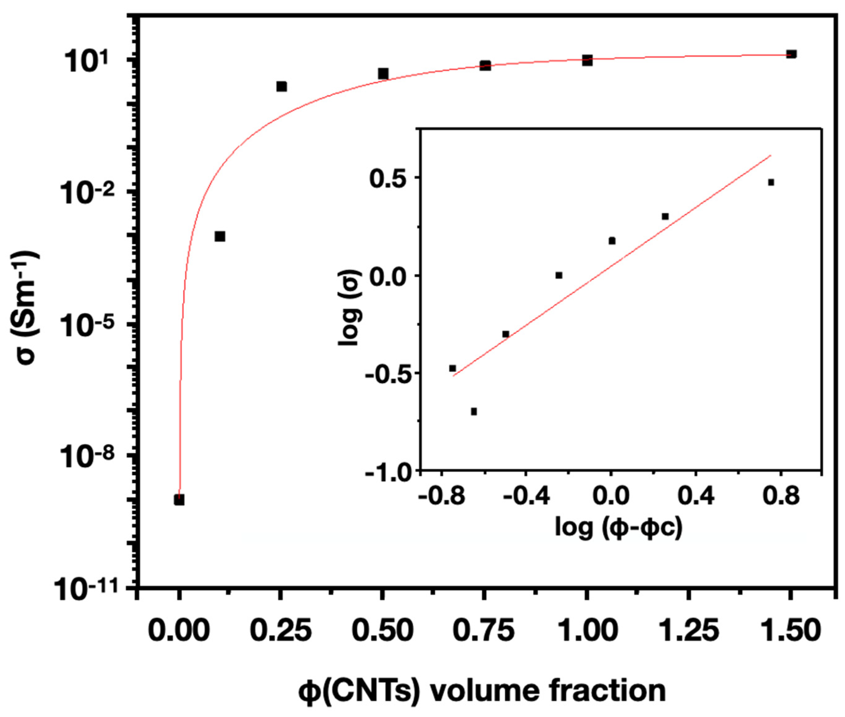
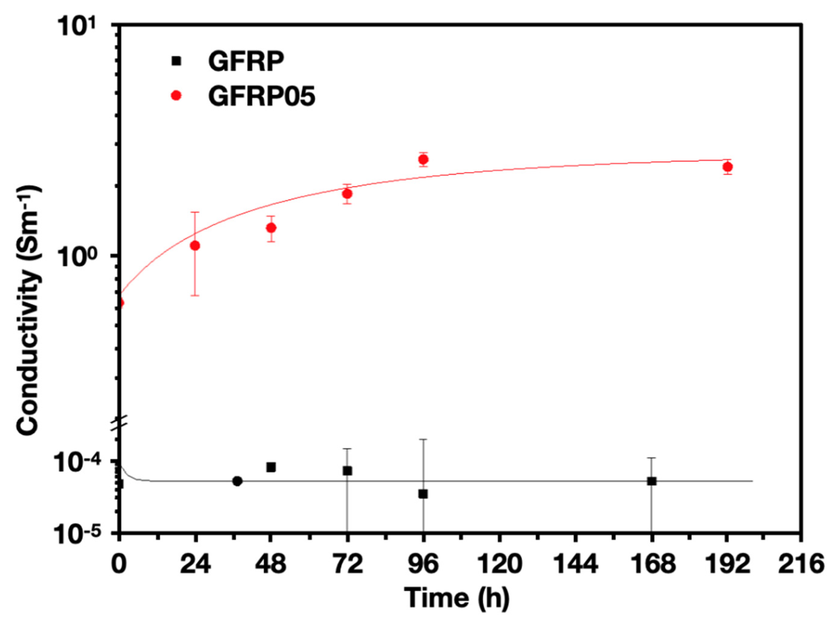
3.2. Electrical Conductivity and Water Diffusion Sensing of Epoxy/CNT and GFRP/CNT

The electrical conductivity of epoxy samples with different CNT filler contents was measured. Figure 4 shows the percolation curve of epoxy/CNT composites. Fitting the curve with Equation (2), a percolation threshold of 0.16 vol. % (0.23 wt. %) can be found. Above a concentration of 0.5–0.75 wt. %, the electrical conductivity reaches the plateau.
To detect the diffusion of sea water, one of several main corrosion agents in the oil and gas industry, the electrical conductivity of composite specimens with different CNT contents were measured and compared during accelerated ageing tests at 80 °C.
As shown in Figure 5, all the samples showed an increase in electrical conductivity, except for pristine samples (samples without CNT). The results can be explained in terms of the presence of ions in the artificial sea water, contributing positively to the conductivity. As water diffused through the sample, ions can bridge CNTs, creating a more robust conductive network.
It was observed that all samples immediately after immersion (time zero) show a higher conductivity in comparison to the dried samples. That could be explained by the formation of a thin layer of (conductive) artificial sea water on the surface of samples which facilitates the establishment of the conductive pathway.
GFRPs with 0.5 wt. % of CNTs (GFRP05) were prepared as described in Section 2.3, tested and compared with pristine GFRP composites (GFRP without CNTs). The GFRP05s were tested under the same conditions as the epoxy/CNT samples (full samples immersion in artificial sea water at 80 ℃). Figure 6 shows the electrical conductivity response during the first two weeks of immersion. Similar to epoxy/CNT nanocomposite, an increase in electrical conductivity was also observed for GFRP05 specimens, but of smaller intensity (within one order of magnitude).

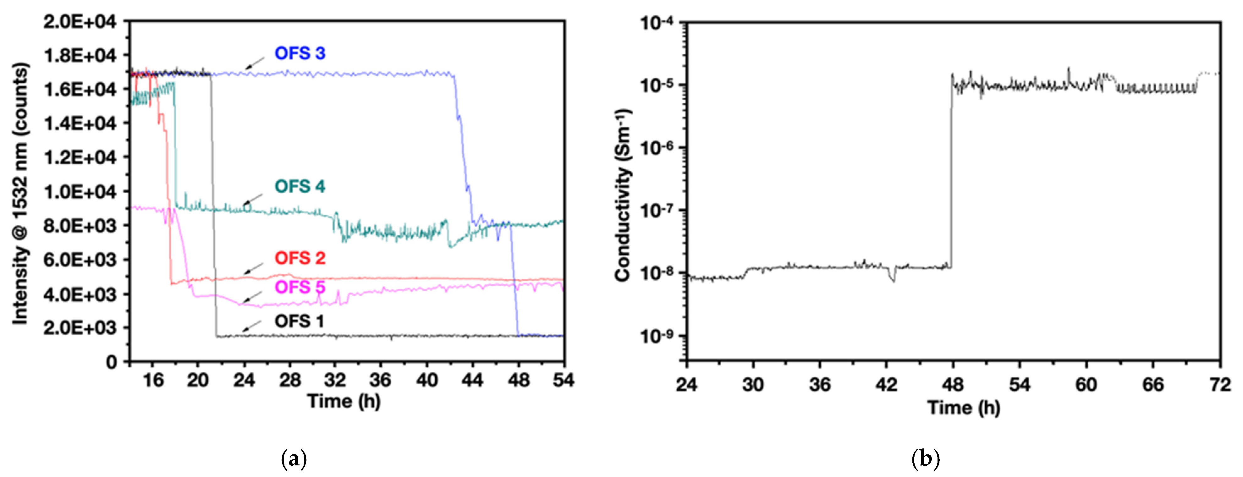
3.3. GFRP with Embedded OFSs and CNTs

Lastly, the two sensors—the optical fibre sensor and electrical sensor—were combined. The diffusion of sea water through the epoxy matrix of the composite was monitored in-situ and in real time by means of both the sensors in the Hybrid composites (H-GFRP).
The H-GFRP was immersed in artificial sea water at 80 °C for 7 days. The reflected signals from the OFSs were recorded every 5 min in the spectral range of 1500 to 1600 nm. The shape of the spectra did not show any change, whereas it showed a sharp decrement in the maximum intensity signal at 1532 nm (the maximum intensity signal provided by the source) which was attributed to moisture diffusion. As a consequence of this moisture diffusion, the spectral attenuation could be determined by the change in the optical properties of the epoxy surrounding the core of the fibre, as already discussed in [7,24,30,33].
Figure 7a shows the signal intensities at 1532 nm recorded from the five OFSs embedded in the H-GFRP. The signals from the different OFSs dropped at different times because they were located at different distances from the specimen surface (measured by means of an optical microscope). OFS 1, 4 and 5 were located at depth of 1.4 ± 0.2 mm and showed a signal drop after approximately 21, 19 and 18 h, respectively. Sensor 2 was located at a depth of 1.3 ± 0.2 mm and showed a signal drop after nearly 13 h. Table 1 shows the diffusion times calculated taking into account the OFS measured distance from the surface and the water diffusion coefficient [21]: 16 ± 4 and 13 ± 4 h, respectively, for OFSs 1, 4, 5 and OFS 2. Hence, OFSs were able to detect the water diffusion with acceptable time accuracy, in accordance with the calculated diffusion time (Table 1). OFS 3 was located between the plies at a depth of about 2.2 ± 0.2 mm and showed a signal drop after 43 h. This value is significantly higher than the diffusion time estimated using Equation (2), which is believed to be due to the presence of GF plies and the CNT coating, acting as barrier to diffusion.
The corrected diffusion equation (Equation (3)) gives a more accurate prediction of the experimental diffusion times of all sensors apart from OFS 3 (Table 1).
On the other hand, Figure 7b displays the increment of the conductivity of the GF plies spray coated with CNT, after 48 h of immersion. The response of the CNTs in this test presents a delay during the first 48 h since the spray coated ply was embedded in the middle by the resin, avoiding any direct contact with the artificial sea water, as in the case of GFRP05 samples.
The location of the deposited CNT layer was close to OFS 2, at a depth of 2.2 ± 0.3 mm. Taking into consideration that the uncertainty of the measurement of depth d by the microscope is about ±0.2 mm, a rough agreement between experimental and theoretical data was found. The experimental signal was obtained at 48 h, while it was expected earlier, at 38 ± 5 h. By applying the correction factor, the gap between experimental and theoretical results narrows (from 10 h to 8 h, approximately). Nevertheless, it demonstrates that both sensors can detect continuously the diffusion of water through the polymer matrix of the composite, providing enhanced reliability for potential online health monitoring of composite structures under extreme environments.
The obtained findings demonstrate the possibility of using either CNTs or OFSs to detect water diffusion through a GFRP laminate. In addition, a dual-sensory system based on combined CNTs and OFSs has been demonstrated with reliable sensing signals for both sensors and the possibility of working together. CNTs were able to detect the water diffusion but the conductivity increment did not match the signal change expected from the OFS. This is believed to be due to a decreased diffusion in presence of CNT network layer, in agreement with the effect of CNT on the reduction of diffusion in neat epoxy.
The possibility of creating a composite with more GF plies spray coated with CNT, positioned at different depths, to monitor the water diffusion through the GFRP, could be considered in the future.

4. Conclusions

In this paper, we reported the development of a dual-sensory system for water diffusion in composites based on the combination of optical fibre sensors and electrically percolated carbon nanotube (CNT) networks. The optical sensor is based on the evanescent wave, which responds with a spectral attenuation, caused by a change in the optical properties of the epoxy surrounding the core of the fibre, during water diffusion. While the electrical sensor is based on the change in electrical conductivity of percolated CNT networks, either dispersed into the bulk epoxy matrix or selectively spray coated onto certain GF plies. The sensing performance on both optical fibre sensor (OFS) and CNTs have been compared.
The electrical conductivity of samples containing dispersed CNTs was measured during an accelerated ageing test in artificial sea water at 80 °C. The tested samples showed an obvious conductivity increment. This was attributed to the presence of ions in the artificial sea water which bridge the CNTs and creates a more robust conductive network, hence contributing positively to the overall conductivity.
Similar conductivity enhancements were recorded for the hybrid glass fibre composites (H-GFRP), where CNTs were spray coated onto GF plies prior to subsequent resin infusion and curing. At the same time, the signals from the different optical fibre sensors, embedded into the H-GFRP, dropped at different times, corresponding to their location (depth) from the sample surface; the OFSs were able to detect the water diffusion in rather good agreement with theoretical predictions of diffusion times.
In conclusion, the potential of using a non-destructive method to provide in-situ and real-time water diffusion monitoring in composites was demonstrated, using optical glass fibre, percolated CNT networks and their combination with a parallel sensory system to provide enhanced reliability.

Author Contributions

C.M.B. and G.d.L.: most of the experimental work; H.Z. and A.K.: technical support and help with manuscript draft preparation; C.S., M.S. (Marco Sangermano), M.O., E.B. and M.S. (Milena Salvo): Conceptualization, supervision and manuscript draft preparation. All authors have read and agreed to the published version of the manuscript.

Funding

This research was funded by the European Union’s Horizon 2020 Programme through a Marie Skłodowska-Curie Innovative Training Network (CoACH, grant number 642557).

Conflicts of Interest

The authors declare no conflict of interest.

References

  1. Davis, D.C.; Wilkerson, J.W.; Zhu, J.; Ayewah, D.O.O. Improvements in mechanical properties of a carbon fiber epoxy composite using nanotube science and technology. Compos. Struct. 2010, 92, 2653. [Google Scholar] [CrossRef]
  2. Koch, M.; Lupton, D. Design and Manufacture of Bushings for Glass Fibre Production; HVG-Colloquium: Dusseldoff, Germany, 2006. [Google Scholar]
  3. Carra, G.; Carvelli, V. Ageing of pultruded glass fibre reinforced polymer composites exposed to combined environmental agents. Compos. Struct. 2014, 108, 1019. [Google Scholar] [CrossRef]
  4. Glass Fiber Differences and Properties, Prince Eng. Build Prince. (n.d.). Available online: https://www.build-on-prince.com/glass-fiber.html (accessed on 18 July 2018).
  5. Gibson, A.G. The Cost Effective Use of Fibre Reinforced Composites Offshore; HSE Books: Newcastle, UK, 2003; p. 140. [Google Scholar]
  6. Crank, J. The Mathematics of Diffusion, 2nd ed.; Clarendon Press: Bristol, UK, 1986. [Google Scholar]
  7. Milsom, B.; Olivero, M.; Milanese, D.; Giannis, S.; Martin, R.H.; Terenzi, A.; Kenny, J.; Ferraris, M.; Perrone, G.; Salvo, M. Glass optical fibre sensors for detection of through thickness moisture diffusion in glass reinforced composites under hostile environments. Adv. Appl. Ceram. 2015, 114, S76–S83. [Google Scholar] [CrossRef] [Green Version]
  8. Bach, H.; Neuroth, N. The Properties of Optical Glass, 2nd ed.; Springer: Mainz, Germany, 1998. [Google Scholar]
  9. Růžek, R.; Kadlec, M.; Tserpes, K.; Karachalios, E. Strain monitoring in stiffened composite panels using embedded fibre optical and strain gauge sensors. In Proceedings of the 7th European Workshop on Structural Health Monitoring (EWSHM 2014–2nd European Conference of the Prognostics and Health Management Society), Nantes, France, 8–11 July 2014. [Google Scholar]
  10. Fibre Bragg Grating (FBG) Sensor Principle, (n.d.). Available online: https://www.fbgs.com/technology/fbg-principle/ (accessed on 17 July 2018).
  11. Stetter, J.R.; Penrose, W.R.; Yao, S. Sensors, Chemical Sensors, Electrochemical Sensors, and ECS. J. Electrochem. Soc. 2003, 150, S11. [Google Scholar] [CrossRef]
  12. Gao, S.; Zhuang, R.-C.; Zhang, J.; Liu, J.-W.; Mäder, E. Glass Fibers with Carbon Nanotube Networks as Multifunctional Sensors. Adv. Funct. Mater. 2010, 20, 1885–1893. [Google Scholar] [CrossRef]
  13. Jiang, W.F.; Xiao, S.H.; Feng, C.Y.; Li, H.Y.; Li, X. Resistive humidity sensitivity of arrayed multi-wall carbon nanotube nests grown on arrayed nanoporous silicon pillars. Sens. Actuators B Chem. 2007, 125, 651–655. [Google Scholar] [CrossRef]
  14. Yoo, K.-P.; Lim, L.-T.; Min, N.K.; Lee, M.J.; Lee, C.J.; Park, C.W. Novel resistive-type humidity sensor based on multiwall carbon nanotube/polyimide composite films. Sens. Actuators B Chem. 2010, 145, 120–125. [Google Scholar] [CrossRef]
  15. Bajpai, J.; Deva, D. Carbon Nanotube-polymer composites for sensor applications. Int. J. Sci. Technol. 2015, 3, 2321. [Google Scholar]
  16. Terrones, M. Science and Technology of the Twenty-First Century: Synthesis, Properties, and Applications of Carbon Nanotubes. Annu. Rev. Mater. Res. 2003, 33, 419–501. [Google Scholar] [CrossRef]
  17. Zhang, H.; Liu, Y.; Huo, S.; Briscoe, J.; Tu, W.; Picot, O.T.; Rezai, A.; Bilotti, E.; Peijs, T. Filtration effects of graphene nanoplatelets in resin infusion processes: Problems and possible solutions. Compos. Sci. Technol. 2017, 139, 138–145. [Google Scholar] [CrossRef]
  18. Liu, Y.; Zhang, H.; Porwal, H.; Tu, W.; Evans, J.; Newton, M.; Busfield, J.J.C.; Peijs, T.; Bilotti, E. Universal Control on Pyroresistive Behavior of Flexible Self-Regulating Heating Devices. Adv. Funct. Mater. 2017, 27, 1702253. [Google Scholar] [CrossRef]
  19. Zhang, H.; Liu, Y.; Kuwata, M.; Bilotti, E.; Peijs, T. Improved fracture toughness and integrated damage sensing capability by spray coated CNTs on carbon fibre prepreg. Compos. Part A Appl. Sci. Manuf. 2015, 70, 102–110. [Google Scholar] [CrossRef]
  20. Zhang, H.; Liu, Y.; Huang, M.; Bilotti, E.; Peijs, T. Dissolvable thermoplastic interleaves for carbon nanotube localization in carbon/epoxy laminates with integrated damage sensing capabilities. Struct. Health Monit. 2016, 17, 59–66. [Google Scholar] [CrossRef]
  21. Marro, B.C.; Olivero, M.; Sangermano, M.; Salvo, M. Towards smart polymer composites: Detection of moisture diffusion through epoxy by evanescent wave optical fibre sensors. Polym. Test. 2018, 71, 248. [Google Scholar] [CrossRef]
  22. Li, Y.; Zhang, H.; Bilotti, E.; Peijs, T. Optimization of Three-Roll Mill Parameters for In-Situ Exfoliation of Graphene. MRS Adv. 2016, 1, 1389–1394. [Google Scholar] [CrossRef]
  23. Li, Y.; Zhang, H.; Crespo, M.; Porwal, H.; Picot, O.; Santagiuliana, G.; Huang, Z.; Barbieri, E.; Pugno, N.M.; Peijs, T.; et al. In Situ Exfoliation of Graphene in Epoxy Resins: A Facile Strategy to Efficient and Large Scale Graphene Nanocomposites. ACS Appl. Mater. Interfaces 2016, 8, 24112. [Google Scholar] [CrossRef] [PubMed]
  24. Rahaman, A.; Kar, K.K. Effect of Coating Time and Temperature on Electroless Deposition of Cobalt-Phosphorous for the Growth of Carbon Nanotubes on the Surface of E-Glass Fibers/Fabric. Full Nanotub. Carbon Nanostruct. 2011, 19, 373–397. [Google Scholar] [CrossRef]
  25. Zakowski, K.; Narozny, M.; Szociński, M.; Darowicki, K. Influence of water salinity on corrosion risk-the case of the southern Baltic Sea coast. Environ. Monit. Assess. 2014, 186, 4871–4879. [Google Scholar] [CrossRef] [Green Version]
  26. Starink, M.J.; Starink, L.M.P.; Chambers, A.R. Moisture uptake in monolithic and composite materials: Edge correction for rectanguloid samples. J. Mater. Sci. 2002, 37, 287–294. [Google Scholar] [CrossRef] [Green Version]
  27. Gagani, A.; Fan, Y.; Muliana, A.H.; Echtermeyer, A.T. Micromechanical modeling of anisotropic water diffusion in glass fiber epoxy reinforced composites. J. Compos. Mater. 2017, 52, 2321–2335. [Google Scholar] [CrossRef]
  28. Montazer, M.; Alimohammadi, F.; Shamei, A.; Rahimi, M.K. In situ synthesis of nano silver on cotton using Tollens’ reagent. Carbohydr. Polym. 2012, 87, 1706–1712. [Google Scholar] [CrossRef]
  29. Salvo, M.; Sangermano, M.; Marro Bellot, C.; Olivero, M. Optical Sensor, Process for Making Such Sensor and Evaluation System Comprising at Least One of Such Sensors. Pat. Appl. 2018WO–IT00059 2018. [Google Scholar]
  30. Marro Bellot, C.; Sangermano, M.; Olivero, M.; Salvo, M. Optical Fiber Sensors for the Detection of Hydrochloric Acid and Sea Water in Epoxy and Glass Fiber-Reinforced Polymer Composites. Materials 2019, 12, 379. [Google Scholar] [CrossRef] [PubMed] [Green Version]
  31. Prolongo, S.; Gude, M.; Ureña, A. Water uptake of epoxy composites reinforced with carbon nanofillers. Compos. Part A Appl. Sci. Manuf. 2012, 43, 2169–2175. [Google Scholar] [CrossRef]
  32. Cavasin, M.; Salvo, M.; Sangermano, M. Study on Accelerated Exposure Testing and Thermal Insulation for a Glass Fibre Reinforced Polymer in Simulated Oil & Gas Environment. Ph.D. Thesis, Politecnico di Torino, Torino, Italy, September 2019. [Google Scholar]
  33. Marro Bellot, C.; Salvo, M.; Sangermano, M. Design, Processing and Characterisation of New Optical Fibre Sensors for Harsh Environment. Ph.D. Thesis, Politecnico di Torino, Torino, Italy, January 2019. [Google Scholar]
Figure 1. Schematic of the hybrid Glass Fibre Reinforced Polymer (H-GFRP) sample: (a) perspective and (b) cross-sectional view. (c) Optical picture of the H-GFRP sample.
Jcs 04 00097 g001
Figure 2. Schematic of the interrogation set up of the combined sensors GFRP sample.
Jcs 04 00097 g002
Figure 3. Gravimetric experiment results of Epoxy05 and GFRP05 samples full immersed into artificial salty water at 80 °C. All samples were tested up to 712 h.
Jcs 04 00097 g003
Figure 4. Electrical conductivity of epoxy samples as a function of filler content.
Jcs 04 00097 g004
Figure 5. Electrical conductivity of 4 different epoxy samples with different concentrations of carbon nanotubes (CNTs) (0, 0.25, 0.5 and 0.75 wt. %) immersed in artificial sea water at 80 °C. Data were recorded every 24 h.
Jcs 04 00097 g005
Figure 6. Electrical conductivity of pristine GFRP composite and GFRP05 composites immersed in artificial sea water at 80 °C. Data were recorded every 24 h over 2 weeks.
Jcs 04 00097 g006
Figure 7. (a) Signal intensity at a wavelength of 1532 nm from the optical fibre sensors (OFSs), (b) continuous monitoring of the conductivity signal of the GF ply, spray coated with CNT, positioned at depth of 2.2 ± 0.3 mm: signal increased after 48 h. The composite was immersed in artificial sea water at 80 °C for 7 days.
Jcs 04 00097 g007
Table 1. Summary of the depth location and signal change of the different embedded optical fibre sensors and the GF ply spray coated with CNT in the H-GFRP.
Sensor TypeDepth (mm)Experimental Time (h)Theoretical Time (h)Corrected Theoretical Time (h)
Optical Glass
Fibre Sensors
11.4 ± 0.2 16 ± 4
21.3 ± 0.11613 ± 216 ± 2
32.2 ± 0.14339 ± 540 ± 5
41.4 ± 0.11816 ± 216 ± 2
51.4 ± 0.11916 ± 116 ± 1
CNTs 2.2 ± 0.24838 ± 540 ± 5

