Article

Design and Validation of a Modified Compression-After-Impact Testing Device for Thin-Walled Composite Plates

by
Markus Linke
1,*,
Felix Flügge
1 and
Aurelio Jose Olivares-Ferrer
1,2
1
Department of Automotive and Aeronautical Engineering, Hamburg University of Applied Sciences (HAW Hamburg), 20099 Hamburg, Germany
2
Department of Mechanical Engineering, Universitat Politècnica de València (UPV), 46022 Valencia, Spain
*
Author to whom correspondence should be addressed.
J. Compos. Sci. 2020, 4(3), 126; https://doi.org/10.3390/jcs4030126
Submission received: 1 August 2020 / Revised: 16 August 2020 / Accepted: 23 August 2020 / Published: 29 August 2020
(This article belongs to the Special Issue Recent Advances in Composite Process Modeling and Characterization)

Abstract

:
Thin-walled fibre reinforced composites like carbon fibre reinforced plastics are very susceptible to strength reductions due to low-velocity impact damages. In aerospace engineering, the dominating failure mechanisms of impact damaged composite structures are usually investigated based on the compression after impact (CAI) test procedure. This enables the determination of the influence of impact damages on the static residual compressive strength. CAI testing procedures are typically applicable to composite plates with thicknesses larger than 3–4 mm. If thinner panels are used, they typically fail near one of the loaded edges of the CAI device, in particular the area of the free edge (which is needed for compressing the panel) and not within the free measuring area. As a consequence, the investigated samples cannot be used as valid tests for the evaluation of the residual strength in CAI testing. In order to enable an investigation of the residual strength of thin-walled plates in CAI testing, a CAI testing device is developed based on an available CAI fixture and a standardized one. For comparability reasons, this new device exhibits the same dimensions as standardized fixtures. It shows a significant improvement with respect to standardized devices concerning the measurement of mechanical behaviour during CAI testing.

1. Introduction

Due to their high specific strength and stiffness, fibre reinforced composites like carbon fibre reinforced plastics (CFRP) are increasingly being used in a wide variety of industries. However, these materials, in particular thin-walled CFRP, are very susceptible to strength reductions due to low velocity impact damages [1]. In aerospace engineering, this strength loss has to be considered during the development and design phase of primary structures by a sufficient damage tolerance which usually leads to weight penalties. It is consequently of great interest to understand the dominating failure mechanisms and to measure their influence on the residual strength and stiffness of impact damaged composite structures.
The influence on the residual strength is typically investigated based on the compression after impact (CAI) test procedure (cp. [2,3,4,5,6,7]). It enables the determination of the influence of impact damages on the static residual compressive strength. It is a structural strength value resulting from the material properties, the laminate layer set-up and the induced damage (like fibre breakage, matrix cracking, delamination, local sub-laminate buckling, as well as their interactions) among others. In the case of thin-walled samples, global buckling can additionally occur before the sample fails due to the influence of geometric imperfections. As a result, CAI testing procedures are typically applicable to composite plates with thicknesses larger than 3–4 mm (cp. [8,9,10]). This is mainly due to the fact that plate buckling in CAI testing devices is intended to be prevented before plate failure is reached. Typical failure mechanisms on composite specimens subjected to CAI testing are usually caused by sub-laminate buckling according to Freitas and Ries [11]. In-plane fibre compressive fracture and interlaminar fracture toughness are key parameters that affect CAI residual strength of composites [12]. In [13], the failure mechanisms are studied experimentally and numerically under CAI testing. Combining high speed cameras and high-fidelity Finite Element models, they observe that delaminations and local buckling propagate rapidly through the specimens till final rupture. Most of the ply rupture is caused by the induced high strains due to sub-laminate buckling. The delaminations grow to the lateral boundaries from the initially damaged area at the centre of the specimens [11,12,13]. Besides, the boundary conditions imposed to the specimens can exhibit a relevant influence on thin-walled laminates. As shown in [14], different undesired failure modes such as brooming or compression shear failure can occur due to the influence of boundary conditions. In the case of thin-walled specimens, these failure modes interact with the global buckling phenomena. But the global buckling of the plate typically should not interact with local failure phenomena due to impact damages, in particular, like local sub-laminate buckling. Therefore, some authors have investigated different modifications of CAI testing devices in order to avoid global buckling in thin-walled laminates [14,15,16,17]. However, it can be assumed that, in real technical applications, an interaction between global buckling modes and the local sub-laminate buckling and the subsequent failure of the plate can occur. This interaction between global buckling modes and local failure in thin-walled plates can in principle be investigated in CAI tests, too. However, many thin-walled plates fail in the area of the loading edges, in particular, in the area of the free sample edge and not within the free measuring area when standard CAI devices are used for low-impact damages. As the free sliding edge is technically required for compressing the test plates, this sample weakening cannot completely be avoided.
In order to reduce the influence of the free sliding edge, a CAI device for thin CFRP plates has been developed in [18]. The samples break primarily within the free measuring range and can thus be evaluated as valid CAI tests. However, this device has a smaller free measuring range compared to standard devices. In addition, a slightly higher standard deviation for the failure load in measurement campaigns is observed compared to a standard fixture. For these reasons, the CAI test device developed according to Linke and García-Manrique [18] has been systematically redesigned (cp. [19]) and evaluated. In particular, it has been taken into account that the CAI samples have the same dimensions as well as the same free measuring area as it is the case for standard devices. This ensures the full comparability of experimental results obtained with other standardized CAI test devices. Moreover, the supports of the CAI samples have been revised in such a way that the best possible visibility of the entire free measuring area is ensured. This is due to the fact that for an investigation of the interaction between global buckling and local failure due to impact damages, the entire free measurement area is ideally visible to digital image correlation (DIC) technology. In that way, a validation and correlation between experimental and numerical simulation results can be achieved for the full visible plate surface.
In the context of this article, a modified CAI test device based on the experimental device according to Linke and García-Manrique [18] is further developed and designed in order to fulfil the previously mentioned requirements such as same plate dimensions as well as same free measuring area like standard devices and good visibility of the measuring area (a detailed list of all requirements can be found in [19]). First, standardized and modified test procedures and equipment are analysed in Section 2 for the subsequent concept development which is generally described in Section 3. In Section 4, the realised CAI solution is described in detail so that the results of CAI testing of a specific CFRP plate problem (defined in Section 5) is illustrated and discussed with respect to available test data according to Linke and García-Manrique [18] in Section 6. The article ends with a summary and a conclusion in Section 7.

2. State of the Art: Compression-After-Impact Testing

For the quantification of the influence of impact damages on the structural behaviour of composite panels, various standardized test methods exist in which the residual compressive strength is measured (see AITM 1-0010 [2], EN 6038 [3], ISO 18352 [4], SACMA SRM 2R-94 [5], ASTM D7137/D7137M [6], BSS 7260 [7]). These standardized CAI test procedures are very similar and can be subdivided into three test phases. In the first phase, a rectangular composite plate (150 × 100 mm²) is subjected to a concentrated transverse impact by means of an impact device. The second phase consists of evaluating the damage by non-destructive testing and measuring the penetration depth of the impactor. In the third phase, the residual compressive strength is measured. For this purpose, the specimen is subjected to a compressive load in the in-plane of the damaged sample until failure occurs. The residual compressive strength, modulus and elongation are calculated from the load compression response of the specimen. The test device for the residual compressive strength investigation consists of a compression test device with a corresponding fixture and a system for strain measurement. Figure 1 shows a CAI test device and its essential components.
As the mechanical fixture of the samples can exhibit a significant influence on the measured residual strength, different assemblies and their construction types for CAI testing devices are examined according to the available standards in the following. Two main design features can be distinguished influencing the quality of CAI testing, namely the tightening of the samples to the CAI test device and, secondly, the realisation of the free sliding edge which is needed for compressing the samples.

2.1. CAI Sample Tightening

There are two main opportunities for tightening the samples to the test device, i.e., by force-locking and form-fitting connections. An example of the force-locking connections as bearing elements of a CAI device according to EN6038 [3] is shown in Figure 2a. An advantage of this constructive solution is the relatively simple and thus favourable production as well as the variability regarding the sample dimensions. A disadvantage of this connection is the hardly quantifiable clamping force applied to the specimen. The lateral bearing force of the specimen (i.e., in loading direction) has a direct influence on the friction force acting during specimen compression. Furthermore, due to the geometrically non-linear behaviour under compression, a deformation in the out-of-plane direction occurs, especially in thin plates, which is aligned by forces acting in the out-of-plane direction of the sample and against the bearing elements. Under certain circumstances, these forces (indicated by red arrow in Figure 2b) can be greater than the clamping forces of the screw connections and release the bearings accordingly. A person carrying out the test has a decisive influence on the fixing conditions of the specimens due to the force-locking bearing arrangement and thus a hardly quantifiable clamping force results. The bearing conditions are difficult to reproduce within a test series if the out-of-plane forces due to buckling are in the range of the friction forces between the screw connection elements in the out-of-plane direction. The latter problem can be solved by form-fitting connections where the movement of the knife edge supports (in the loading direction) is restrained by screws in the out-of-plane direction (cp. detail in Figure 2c). The latter solution is utilized, e.g., in AITM 1-0010 [2].

2.2. Free Sliding Edge

The second essential design feature of CAI testing devices which can influence the failure modes of thin-walled specimens concerns unsupported areas of the sample plate. The samples exhibit free sliding edges which are necessary to a certain extent in order to compress the specimens. In Figure 3, the areas of free plate edges for different CAI standards are schematically shown. The nominal dimension of the samples is 100 × 150 mm2, as indicated by the surrounding rectangle. The hatched areas show the clamped part of the plates. The simply supporting bearings in the load direction of the sample (z-axis) are marked by the dotted lines. The non-supported plate areas of the CAI fixtures according to EN6038 [3], ISO 18352 [4] and SACMA SR 2R-94 [5] are shown in red in Figure 3a. They are located below the upper clamping head (exact dimensions cannot be quantified due to lack of information for these devices).
In contrast to that, the compression test device according to AITM 1-0010 [2] exhibits four areas of free plate edges (cp. Figure 3b), i.e., it shows an incomplete clamping at the lower as well as at the upper plate edges. In the case of an undamaged or only very slightly damaged panel, the weakening of the panel due to impact damage may be less than that caused by a free panel edge. For this reason, in standardized CAI tests, specimen rupture almost always occurs at the free edge area which is why CAI strength is generally underestimated for slightly damaged or undamaged specimens [15,16,17,18].
Apart from the standards, some scientific publications describe problematic failure modes in the area of the loaded edges and the corresponding reduction of residual strength in CAI tests due to failure at the supports as a result of a weakening effect caused by free or unsupported plate edges [15,16,17,18].
According to Sanchez-Saez et al. [15], various modifications of compression test fixtures are tested to avoid the reduction of residual strength. Two-part anti-buckling plates are connected to the upper and lower clamping, whereby the area of the free sliding edge is centred to the specimens. As a result, failure at the supports is prevented and rupture occurs in the middle of the samples. However, the reduction in strength due to the free sliding edge cannot be demonstrated as its length does not change. The sample damage and the weakening of the free sliding edge coincide more or less in the loading direction. Furthermore, the geometry of the specimens is adapted so that no longer standardized dimensions are realised.
The scientific work according to Linke and García-Manrique [18] deals more closely with the effect of free edge weakening in CAI tests. In order to reduce the influence of the free edge in CAI tests on the measured strength of thin-walled specimens, a standardized CAI test device is modified so that undamaged specimens no longer primarily break in the area of the free sliding edge. The modification involves geometrically modified clamping elements at all four corners to stiffen the free edge area. In an experimental study, the results of the modified CAI test fixture are compared to those of a standardized CAI test fixture (Instron GmbH, High Wycombe, UK) which complies with the AITM 1-0010 [2] and ISO 18352 [4] standards. The corresponding boundary conditions are given in Figure 4a. The realized boundary conditions by the modified CAI test fixture are shown schematically in Figure 4b.
The specimen of the modified CAI test fixture is fully clamped along the entire loaded edge. In order to further reduce the influence of the free plate edge, the upper clamp is enlarged in the z-direction and protrudes into the area between the simply supported bearings. The free sliding edges in the lower part of the test fixture are not required for compression and are replaced by a clamped support running along the whole loaded edge in comparison to [2] (cp. Figure 4b). Since a certain free edge length is required for specimen compression in the upper part, the free edge dimension has been maintained for approximately 4 mm. A test campaign showed that the failure no longer occurs at the loaded supports with the modified device in contrast to the standard one. Moreover, the mean failure stress measured with the modified CAI test fixture is significantly higher than that of the standardized device indicating that the weakening effect of the free sliding edge is reduced. However, the modified device has a smaller free measuring range compared to the standard device. And it exhibits a slightly higher standard deviation for the failure load. Moreover, a force-locking constraint of the supports is chosen so that well defined boundary conditions cannot be applied easily in the case of buckling of thin-walled samples where high reaction loads in the out-of-plane direction of the samples can potentially occur. Besides that, the screws of force-locking attachment limit the view on the free measuring area. Therefore, a new development and design process is started in order to eliminate these mentioned shortcomings.

3. Concept Development for a Modified CAI Testing Device

The development process of a new CAI test device is fundamentally based on VDI Guideline 2221 [20]. In the first step, basic requirements are defined which result from the task, from standards and guidelines as well as from the test sequence. The development process is oriented along the shortcomings of the modified CAI testing device according to Linke and García-Manrique [18] as samples which are tested with this device no longer fail at the loaded supports. Due to that, the following main requirements are defined:
  • Free measuring area agrees with dimensions of applicable standards due to comparability reasons.
  • Avoid strength reduction due to free sliding edges as far as possible.
  • Full visibility of free measuring area in order to enable DIC measurements on full free surface.
More detailed requirements are derived based on the Ishikawa method where graphical representations of causes that lead to or significantly influence potential results are used. The objective is to identify all relevant influencing factors and their effect on the final constructive solution. The process is started with the problem description, in the case of the CAI device, with the rupture of thin-walled composite plates in the vicinity of the free sliding edge as well as with the shortcomings of force-fitting supports. Based on that, potential causes are identified and summed up to domains like practical device handling, constructive realisation of intended supports etc. In this manner, the requirements are expanded and a comprehensive list of requirements is created that includes all necessary framework conditions (cp. [19] for details) in the first step. The requirements are weighted according to their significance and form the basis for all further working steps in the design and development process. In the second step, a functional analysis is performed. The objective of this is to determine the individual functions which must be fulfilled by the system to be developed. The functions form the basis for subsequent brainstorming and divide the complex technical problem into manageable individual problems. In the third step, solution variants for the implementation of the functions are developed. This is done based on the method of the morphological box. The proposed solutions are listed in pictorial form, as a sketch or photo or as a written word. The listing in the columns is arbitrary so that partial solutions which stand on top of each other in the same column, do not stand in connection with each other. The aim is to combine the partial solutions in the most diverse but meaningful way, resulting in several solution variants for the overall function. In the fourth step, the best variant for the task solution is determined by a suitable evaluation procedure. For this purpose, all solution variants are checked for compliance with the requirements from the requirements list in tabular form. Furthermore, a weighting matrix is created which enables a clear comparison of the defined requirements. Finally, a utility value analysis according to VDI 2221 [20] is carried out using the previously determined data. The aim is to find the optimal solution for the CAI test device to be developed for thin-walled composite panels. The best solution found within the scope of the utility value analysis fulfils 86% of the requirements and thus represents a “good solution” (cp. [19]). Consequently, the conceptual contents of this solution variant are used and implemented within the design process.

4. CAI Solution

Selected design features of the developed CAI device and various modifications of the individual assembly elements are shown and explained in the following. 
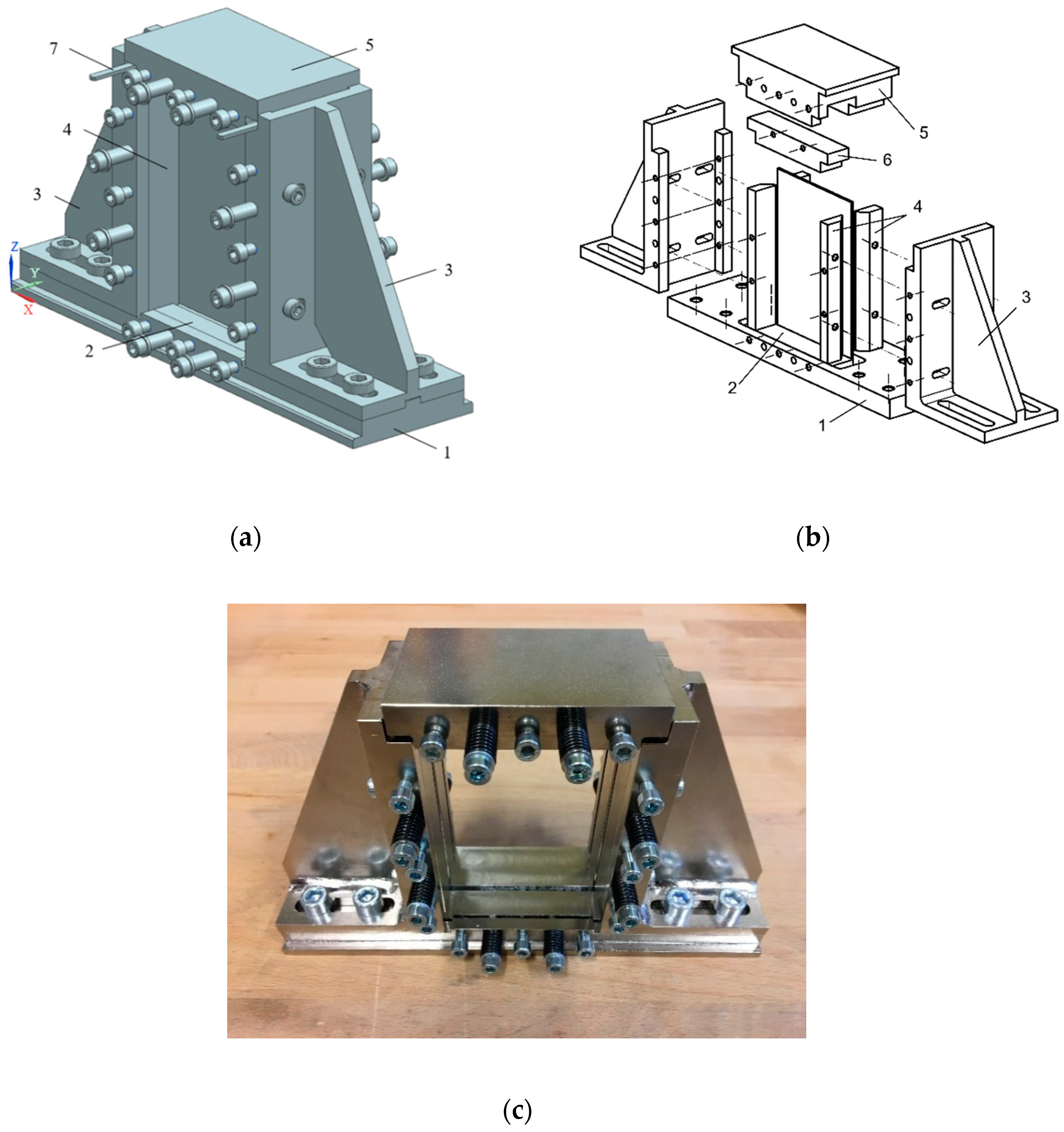
Figure 5 shows the realised CAI testing device. The coordinate system shown in Figure 5a is used to describe the assembly and the individual parts.
(1) Base plate: This component forms the device base. It transmits the forces to the underside between the sample and the hydraulic press. In addition, the base plate forms the support and guide for the bottom clamping plate (2) which realizes the bottom clamped support. The two angle frames (3) are fixed to the base plate with a fitting groove and four M10 screws each. This minimizes the rotational movement of the angle frames around the vertical axis and a translational movement in the y-direction. As a result, the knife edge blades (4) can be used to position the sample laterally with high accuracy.
(2) Bottom clamping plate: The bottom clamping plate lies in the z-direction in a recess in the base plate (1). The clamping plate is guided in the y-direction by two spacer sleeves and two M6 × 35 hexagon socket screws. By screwing in three further M6 × 16 hexagon socket screws, the clamping plate is pressed against the test specimen. The specimen is then pressed against the rear edge of the cut-out in the base plate and clamped. Using two M6 washers and two compression springs surrounding the spacer sleeves, the clamping plate is pressed into its initial position by spring force when the M6 × 16 hexagon socket screws are not screwed in. The lower clamping plate has a height of 8 mm in the area of the clamping surface which complies with applicable standards. The width of the clamping plate is 120 mm so that the specimens are clamped in the lower area over the entire width.
(3) Angle frame: These two components are used to hold the four knife edge blades. The angle frames are designed to be mirror symmetrical so that they only have to be manufactured in a simple version. The angle frames are each provided with two oblong holes in the lower area. Due to that, they can be infinitely adjusted in the x-direction. With an appropriate upper clamping, specimens with a width of up to 120 mm can be tested. Furthermore, the winding frames have holes and threads on both sides for holding the knife edge blades. Thus, the position of the lateral bearing in the y-direction and the out-of-plane position of samples can be changed.
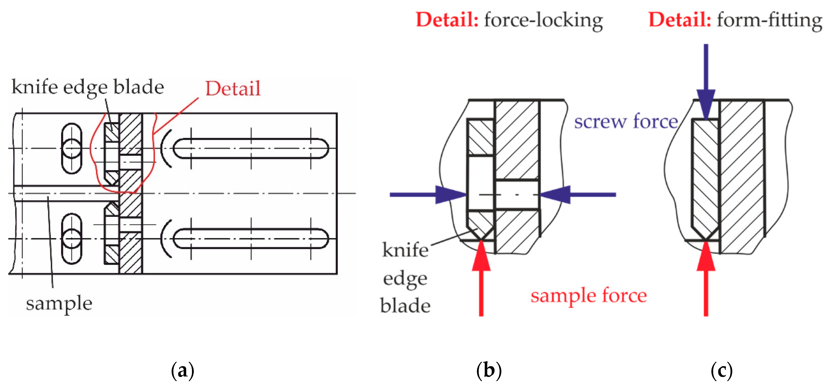
(4) Knife edge blades: They represent the lateral supports of the specimen and rest in the lower area on the lower clamping plate and the base plate. The knife blades are clamped according to the same principle as the lower clamping plate. The knife edge blades are also designed in accordance with the ISO 18352 standard [4] with a radius of 1 mm and single mirror symmetry. On the one hand, the small radius is intended to minimize the contact surface between the knife edge blade and the sample so that the lateral bearing arrangement comes as close as possible to the fixed bearing from theory, and on the other hand, the knife edge blade should not significantly deform the sample. The tip is arranged at the side so that the optical strain measurement is improved again, since the free measuring surface is visible up to the bearing.
(5) Top clamping head: This component transmits the forces on the upper side between the specimen and the hydraulic press and forms the mounting and guide of the upper clamping plate (6). Here, the clamping of the upper clamping plate is realised according to the same principle as that of the lower clamping plate. In order to be able to test samples composed of different materials and thus different sample stiffnesses, the upper clamping is made in two different versions. This is due to the fact that the free sliding edge should be as small as possible. The design difference is concerned with the shoulder height. This is 6 mm for the first and 8 mm for the second version resulting in a free edge length of 2 or 4 mm between the upper clamping and the knife edge blades during assembly.
(6) Top clamping plate: The upper clamping plate (not visible in Figure 5a but in Figure 5b) lies in the z-direction in a recess on the upper part of the top clamping head. This component is also designed and manufactured in two versions. The clamping plates for realising the clamped support are adapted to the corresponding contour and dimensions of the clamping head. The height of the upper clamping plates amounts to 10 mm, unlike the lower clamping plate. The dimension is chosen in such a manner that the free measuring surface is as large as possible but the free sliding edge is still sufficiently stabilised.
(7) Measuring holder: This component is used for exact positioning and storage of the specimen. The holders are placed between the specimen and the angle frame.
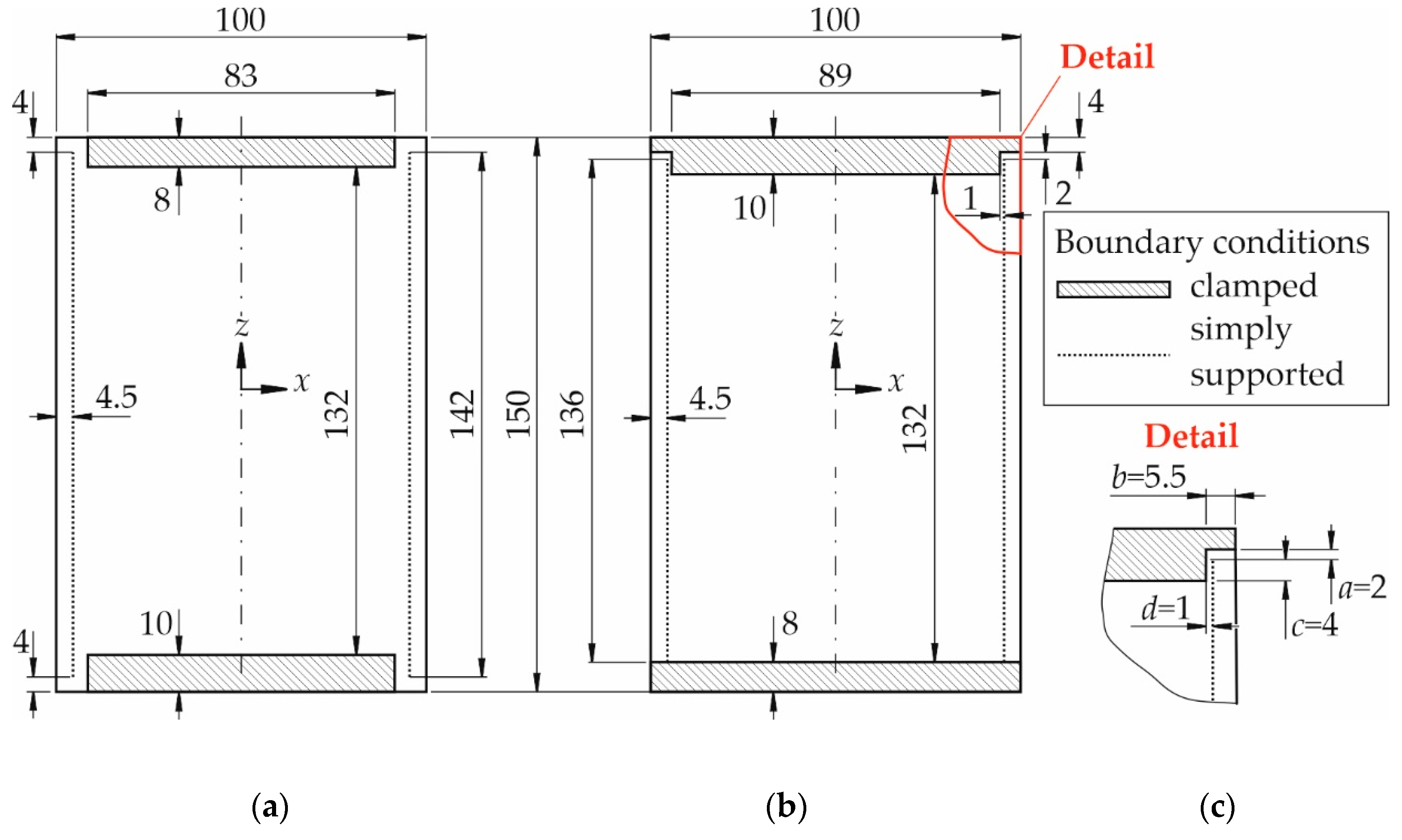
The plate bearings and the individual geometric modifications are shown schematically for the CFRP plate test version in Figure 6b,c with respect to AITM 1-0010 standard [2] in Figure 6a. In order to reduce the number of the free sliding edges as far as possible, only at the upper head free edges are considered. The loaded edges of the specimen are clamped over the entire width. In combination with the 136 mm high lateral simply supported bearing, which is arranged between the top and bottom clamps, an unsupported free plate edge of only two 2–4 mm results, depending on the use of the upper clamping head (cp. free edge a according to Figure 6c). The dimensions are selected in such a manner that the free edge lengths are as small as possible but, at the same time, there is still sufficient space for sample compression until the specimens fail. The minimum dimensions for testing CFRP specimens are determined using experimental and numerical CAI tests [18,19,20,21]. In the upper corners, the two free edges are stiffened by geometry adaptations of the support. The stiffening effect is mainly caused by limiting the degrees of rotational freedom. This is due to the fact that plate rotations in this area induce additional bending stresses, reducing the failure load. Moreover, sample tightening is clearly simplified in comparison to the device according to Linke and García-Manrique [18] and as easy as it is the case for commercially available devices like devices according to AITM 1-0010 standard [2]. The device is applicable up to a compressive load of 100 kN.
In order to illustrate the modifications compared to the standard device, shown in Figure 6a, the influence of geometric parameters in the vicinity of the free sliding edge is discussed in the following based on the detail according to Figure 6c. This detail is indicated in red in Figure 6b. The shorter the free edge a has been selected according to Figure 6c, the stiffer the panel becomes near the free edge. The simply supported edge allows the intended rotations around the z-axis of the plate but the rotational degrees of freedom around the x-axis are constrained. The clamping with length b reduces the degrees of rotational freedom about the x- and z-axes near the free plate edge compared to [2] (cp. Figure 6a). As a consequence, the specimens are clamped over the entire width and a more uniformly distributed compressive force results so that stress concentrations and notch effects are expected to be reduced. Dimension c creates a kind of overhang between the clamped upper part and the knife blades. The upper clamping protrudes laterally over the knife blades. This also reduces the degrees of rotational freedom around the x- and z-axes at the free plate edges. Due to the lateral alignment of the knife blades, dimension d can be reduced to 1 mm. The assembly results in a free sample area of 132 × 89 mm2 which complies with applicable standards.

5. Specimens and Test Campaign

For the sake of comparability, specimens composed of the same materials and same layer set-up according to Linke and García-Manrique [18] are used. The specimens consist of carbon unidirectional (UD)-layers and two outer carbon twill weave layers. The laminate exhibits a symmetrical layer set-up with [twill weave, 0°, 90°, 0°, 90°, 0°, 90°]sym. The 0°-direction of the UD-layers coincides with the loading direction during CAI testing. Sample geometry is chosen according to AITM1-0010 [2]. It amounts to 99.98 (±0.02) mm × 149.98 (±0.05) mm.
Undamaged specimens are chosen as they are the most challenging samples for checking the improvements concerning the weakening due to free sliding edges. With undamaged samples, there is no expected weakening of the plates at a specific location, i.e., in the middle of the plate as it is the case for damaged samples. Therefore, the plates should break at the weakest point which is given by the mutual interaction between plate, loading state and testing device. If the free sliding edges still exhibit a significant weakening, this influencing factor is expected to be identified best with undamaged samples where no prescribed weakening exists, i.e., plate rupture should occur in the vicinity of the free sliding edges.
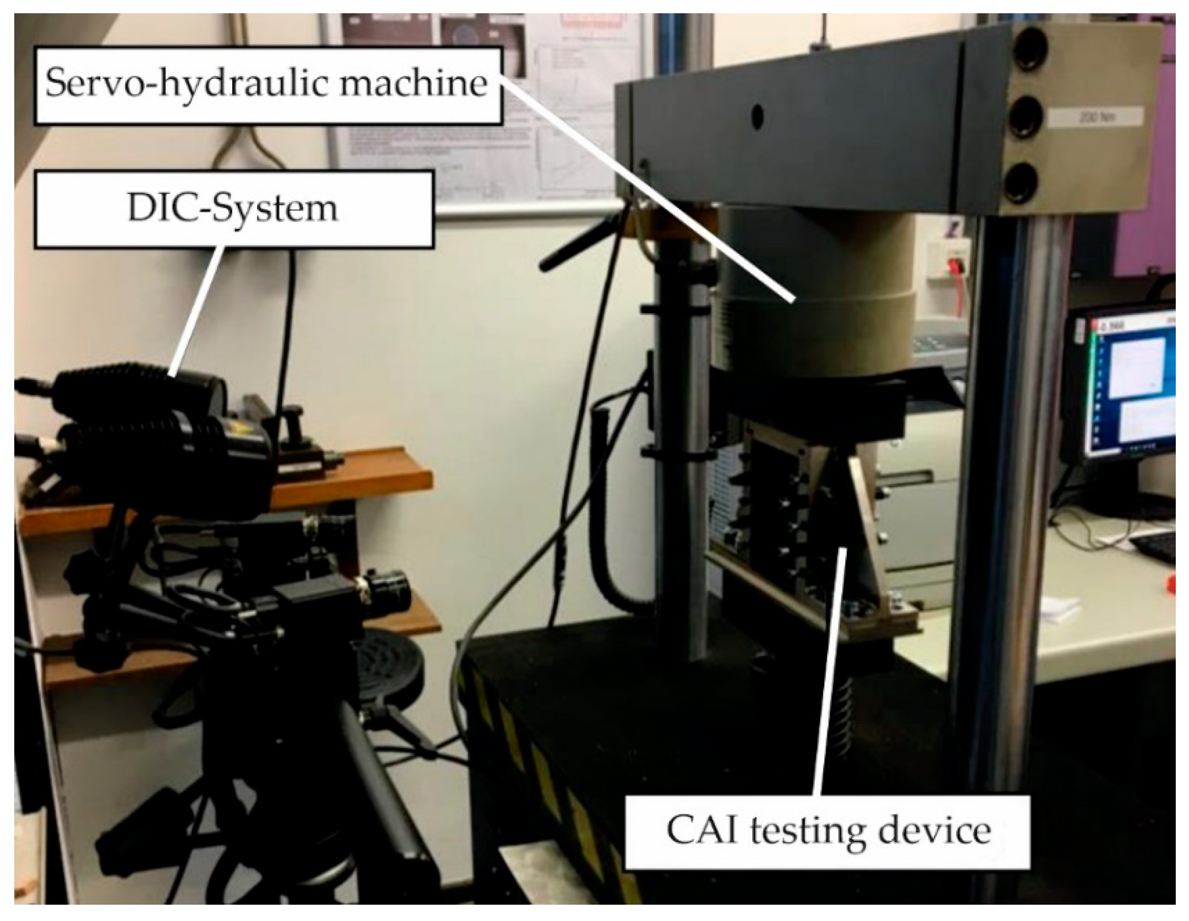
Tests with the new device are carried out using a servo-hydraulic material testing device (Schenck Hydropuls PSA, PZV 1865, Schenck AG, Darmstadt, Germany) equipped with Instron measuring instrumentation (Instron Deutschland GmbH Calibration Service, Darmstadt, Germany). Load controlled testing with a rate of 0.25 kN/s is applied. The averaged displacement rate amounts to about 0.5 mm/min. Displacements on the sample surface are measured with a stereo pair camera DIC system ARAMIS (5 M sensor configuration, 2448 × 2050 pixel, Gom Gesellschaft für optische Messtechnik mbH, Braunschweig, Germany). The DIC procedure is based on the fundamentals explained in [22]. The DIC system was calibrated before the tests according to the requirements defined in [23]. The data recording rate is 1 Hz. The general test set-up is illustrated in Figure 7.
The detailed description of the setting and use of the modified construction according to Flügge [19] serves as a user manual for performing CAI tests with the new modified compression test device. This reduces or avoids errors and inaccuracies within the measurement process by the human factor, thereby improving the quality of the measurement results.
The test results of the new CAI device (called new CAI device below) are compared to available results from a standard device according to AITM1-0010 [2] (called CAI-standard) as well as from a modified device according to Linke and García-Manrique [18] (called CAI acc. to [18]).

6. Test Results and Discussion

6.1. Location of Fracture and Validity of Test Results

Photographs and sketches of the specimen fracture tested with the new CAI device are shown in Figure 8 and Figure 9. The damaged front sides (where the displacements are optically measured) of the specimens tested with the new CAI device are shown in Figure 8.
For the sake of clarity, the fracture lines on the sample surface extracted from Figure 8 are compared to the results of a standard CAI and a modified device (both according Linke and García-Manrique [18] called here CAI-standard resp. CAI acc. to [18]). The outer rectangles in Figure 9 represent the CAI samples with the nominal dimensions of 100 × 150 mm². Dotted lines indicate the knife edges realizing simply supported edges. Dashed areas show the surfaces where the samples are flatly fixed to the CAI device, i.e., where a clamped support can be assumed. The red lines indicate the fracture which is observed on the sample surface where the displacements are optically measured by the DIC technique. This side is called front side in the following.
The fracture lines are all located at the upper loaded edge for the CAI-standard device, i.e., there is no valid test result for determining the residual compressive strength. In contrast to this CAI-standard device, the modified CAI device according to Linke and García-Manrique [18] and the new CAI device exhibit both four valid samples as the fracture lines are located significantly far away from the loaded edges. The new CAI device consequently exhibits a sufficient failure behaviour like the CAI device according to Linke and García-Manrique [18].

6.2. Reproducibility of Testing Results

The failure stress is shown in Table 1 and the mean stress versus the shortening of the plate is illustrated in Figure 10. The shortening is computed based on the measured displacements obtained by the mentioned DIC system in the z-direction in the plate centre line (i.e., symmetry line) over a length of 100 mm with a centred midpoint of the free window (coordinates x = 0 and z = 0).
The measurements with the new CAI device show a significantly reduced standard deviation. This can also be seen in Figure 10 where the curves exhibit only small differences in contrast to the results of the other two devices. Furthermore, the failure load has increased. This could be due to the fact that the samples tested with the new CAI device are about 2 mm wider resulting in larger overhangs between the lateral supports and the sample edge (at least 4.5 mm possible, cp. Figure 6b). The load concentrations due to nonlinear behaviour at the simply supported edges are usually not so pronounced as it is the case for smaller overhangs. As a result, a higher overall CAI loading can be withstood. With the new CAI device, a significantly improved reproducibility can thus be achieved.

6.3. Boundary Conditions with the New Device

In order to check the boundary conditions introduced to the specimens by the new CAI device, the out-of-plane displacements along the symmetrical line in the global z- (vertical) and x-direction (horizontal), respectively, are shown in Figure 11a,b. These curves correspond to the loading-state just before failure of the specimens occurs. In contrast to Figure 11a, the curves from Figure 11b do not reach zero values at the ends of the symmetrical line because the camera orientations obscure small zones close to the lateral supports.
As expected, different out-of-plane curves are obtained at each symmetrical line of the specimens due to the different boundary conditions introduced to the edges of the specimen free measuring area. In Figure 11a, the out-of-plane displacements and slopes of the curve ends tend to zero due to the clamped boundary conditions imposed at the top and bottom of the specimens. In contrast to Figure 11a, the ends of the curves in Figure 11b corresponding to the specimen areas supported by knife edges, should impose simply supported boundary conditions with zero out-of-plane displacements. Nevertheless, as the ends of the curves (x = ±45 mm) cannot be measured, the simply supported boundary condition cannot be checked sufficiently.

6.4. Visible Accessibility of Free Measuring Area

In Figure 12 the out-of-plane displacement is illustrated by laying it over the measuring devices. Colour red indicates the largest out-of-plane displacements and colour blue the smallest ones. Compared to CAI device acc. to [18] shown in Figure 12a, almost the overall free measuring range can be detected and evaluated by the DIC system with the new CAI device shown according to Figure 12b. Only areas where both cameras (stereo pair) do not have free sight cannot be evaluated. Areas which are located directly at the supports cannot be detected either due to the same reason. Nevertheless, an excellent view on the measuring surface is possible so that Finite Element calculations can be compared easily to experimental results obtained by the new CAI device.

7. Conclusions

A new CAI testing device is designed and experimentally tested. It conforms with standard procedures and with the sample geometry of typical CAI standard test devices. Consequently, results obtained by this device can be compared to existing testing results without any restrictions. No modification of standard procedures is necessary if this CAI testing device is utilized. Moreover, valid testing results can be obtained also for thin-walled plates which is usually difficult to achieve by using standard devices as they require minimum plate thicknesses of 3–4 mm. At the same time, the testing results of the new CAI device exhibit a low variation, i.e., a better reproducibility of testing results can be achieved. Due to the specific shape of the knife edge supports in the loading direction, the overall free measuring area of the samples is almost visibly accessible, enabling a better comparison of DIC measurements with numerical computations for surface displacements. The new CAI device is consequently very suitable for CAI testing of thin-walled samples.

Author Contributions

Conceptualization, M.L. and F.F.; methodology, M.L. and F.F.; validation, M.L., F.F. and A.J.O.-F.; investigation, M.L., F.F. and A.J.O.-F.; resources, M.L.; data curation, M.L., F.F. and A.J.O.-F.; writing—original draft preparation, M.L., F.F. and A.J.O.-F.; writing—review and editing, M.L. and A.J.O.-F.; visualization, M.L., F.F. and A.J.O.-F.; supervision, M.L.; project administration, M.L.; funding acquisition, M.L. All authors have read and agreed to the published version of the manuscript.

Funding

The manufacture of the New CAI device was funded by the Faculty of Engineering & Computer Sciences of HAW Hamburg based on the incentive research funding in 2018.

Acknowledgments

The authors gratefully acknowledge the support by Herbert Theilen (Laboratory of Lightweight Design of HAW Hamburg) for the fruitful discussions about CAI testing devices as well as for the assistance while carrying out the experimental investigations. The financial support by the Faculty of Engineering & Computer Sciences of HAW Hamburg enabling the manufacture of the New CAI device is very much appreciated by the authors.

Conflicts of Interest

The authors declare no conflict of interest.

References

  1. Abrate, S. Impact on Composite Structures; Cambridge University Press: New York, NY, USA, 1998; ISBN 9780521473897. [Google Scholar]
  2. Airbus Test Method: Fibre Reinforced Plastics—Determination of Compression Strength after Impact; 0,10,2005. Reference Number AITM1-0010; Airbus S.A.S.: Blagnac, France, 2005.
  3. European Standard: Aerospace Series—Fibre Reinforced Plastics—Test Method—Determination of the Compression Strength after Impact; German and English Version EN 6038: 0,2,2016; Beuth Verlag GmbH: Berlin, Germany, 2016.
  4. International Standard ISO 18352 Carbon-Fibre-Reinforced Plastics—Determination of Compression after Impact Properties at a Specified Impact-Energy Level; Reference Number ISO 18352: 30,09,2009 (E); Beuth Verlag GmbH: Berlin, Germany, 2009.
  5. SACMA Recommended Test Method for Compression after Impact Properties of Oriented Fiber-Resin Composites SRM 2R-94; Suppliers of Advanced Composite Materials Association: Arlington, VA, USA, 1994.
  6. ASTM Test Method: Standard Test Method for Compressive Residual Strength Properties of Damaged Polymer Matrix Composite Plates; 0,0,2017. ASTM D7137/D7137M; American Society for Testing and Materials (ASTM): West Conshohocken, PA, USA, 2017. [CrossRef]
  7. Boeing Advanced Composite Compression Tests. Boeing Specification Support Standard BSS 7260; The Boeing Company: Seattle, WA, USA, 1988.
  8. Aoki, Y.; Yamada, K.; Ishikawa, T. Effect of hygrothermal condition on compression after impact strength of CFRP laminates. Compos. Sci. Technol. 2008, 68, 1376–1383. [Google Scholar] [CrossRef]
  9. Bull, D.J.; Spearing, S.M.; Sinclair, I. Observations of damage development from compression-after-impact experiments using ex situ micro-focus computed tomography. Compos. Sci. Technol. 2014, 97, 106–114. [Google Scholar] [CrossRef]
  10. Liv, Y.; Guillamet, G.; Costa, J.; González, E.V.; Marín, L.; Mayugo, J.A. Experimental study into compression after impact strength of laminates with conventional and nonconventional ply orientations. Compos. Part. B Eng. 2017, 126, 133–142. [Google Scholar] [CrossRef] [Green Version]
  11. De Freitas, M.; Reis, L. Failure mechanisms on composite specimens subjected to compression after impact. Compos. Struct. 1998, 42, 365–373. [Google Scholar] [CrossRef]
  12. Abir, M.R.; Tay, T.E.; Ridha, M.; Lee, H. P Modelling damage growth in composites subjected to impact and compression after impact. Compos. Struct. 2017, 168, 13–25. [Google Scholar] [CrossRef]
  13. Sun, X.C.; Hallett, S. R Failure mechanisms and damage evolution of laminated composites under compression after impact (CAI): Experimental and numerical study. Compos. Part. A Appl. Sci. Manuf. 2018, 104, 41–59. [Google Scholar] [CrossRef] [Green Version]
  14. Nettles, A.T.; Hodge, A.J. Compression-after-impact testing of thin composite materials. In Proceedings of the 23rd International SAMPE Technical Conference, Kiamesha Lake, NY, USA, 21–24 October 1991; NASA Marshall Space Flight Center: Huntsville, AL, USA. [Google Scholar]
  15. Sanchez-Saez, S.; Barbero, E.; Zaera, R.; Navarro, C. Compression after impact of thin composite laminates. Compos. Sci. Technol. 2005, 65, 1911–1919. [Google Scholar] [CrossRef] [Green Version]
  16. Remacha, M.; Sanchez-Saez, S.; López-Romano, B.; Barbero, E. A new device for determining the compression after impact strength in thin laminates. Compos. Struct. 2015, 127, 99–107. [Google Scholar] [CrossRef] [Green Version]
  17. Caminero, M.A.; García-Moreno, I.; Rodriguez, G. Experimental study of the influence of thickness and ply-stacking sequence on the compression after impact strength of carbon fibre reinforced epoxy laminates. Polym. Test. 2018, 66, 360–370. [Google Scholar] [CrossRef]
  18. Linke, M.; García-Manrique, J.A. Contribution to reduce the influence of the free sliding edge on compression-after-impact testing of thin-walled undamaged composites plates. Materials 2018, 11, 1708. [Google Scholar] [CrossRef] [PubMed] [Green Version]
  19. Flügge, F. Konstruktion und Validierung einer modifizierten Compression-After-Impact Prüfvorrichtung für Dünnwandige Compositplatten. Master’s Thesis, Hamburg University of Applied Sciences, Hamburg, Germany, 2019. [Google Scholar]
  20. Verein Deutscher Ingenieure—VDI: VDI 2221—Methodik zum Entwickeln und Konstruieren technischer Systeme und Produkte (Systematic Approach to the Design of Technical Systems and Products); VDI-Verlag: Düsseldorf, Germany, 1993.
  21. Olivares-Ferrer, J.A. Finite elements modeling of Compression-After-Impact test for laminated composite thin plates with initial delaminations. Master’s Thesis, Universidad de Politècnica de València, Valencia, Spain, 2018. [Google Scholar]
  22. Górszczyk, J.; Malicki, K.; Zych, T. Application of digital image correlation (DIC) method for road material testing. Materials 2019, 12, 2349. [Google Scholar] [CrossRef] [PubMed] [Green Version]
  23. GOM mbH. ARAMIS v6.3 User Manual—Software; GOM Optical Measuring Systems: Braunschweig, Germany, 2014; Available online: www.gom.com (accessed on 27 August 2020).
Figure 1. Schematically illustrated CAI test device and its components according to Flügge [19] with test plate (1), lower clamps (2), clamping plate (3), knife edge plates (4), top head clamping (5), angle frames (6) and base plate (7).
Jcs 04 00126 g001
Figure 2. (a) Top view of the force-locking bearing attachment in loading (lateral) direction of a compression device according to Linke and García-Manrique [18], (b) forces in force-locking attachment (red: out-of-plane force of sample, blue: screw force), (c) forces in form-fitting bearing attachment (colours like before).
Jcs 04 00126 g002
Figure 3. Schematic dimensions (100 by 150 mm2) of CAI sample and its supports (the unsupported areas are indicated in red) according to (a) EN 6038 [3], ISO 18352 [4] and SACMA SRM 2R-94 [5] and (b) AITM 1-0010 [2].
Jcs 04 00126 g003
Figure 4. Boundary conditions for specimens (a) according to AITM 1-0010 [2] and (b) according to Linke and García-Manrique [18] (figure reproduced with permission from [18]).
Jcs 04 00126 g004
Figure 5. (a) Assembly of CAI device and (b) exploded sketch of CAI device both with base plate (1), bottom clamping plate (2), angle frame (3), knife edge plates (4), top loading head (5), top clamping head (6), measuring holder plate (7), (c) photograph of device (figures reproduced and modified with permission from [19]).
Jcs 04 00126 g005
Figure 6. Boundary conditions for specimens according to (a) AITM 1-0010 [2], (b) new device, (c) geometric modifications of new device in CFRP design (figure reproduced and modified with permission from [18]).
Jcs 04 00126 g006
Figure 7. Test set-up (figure reproduced and modified with permission from [19]).
Jcs 04 00126 g007
Figure 8. Front side of tested specimens using New CAI device.
Jcs 04 00126 g008
Figure 9. Fracture lines observable on sample surface for CAI-standard, modified CAI device (both results according to Linke and García-Manrique [18]) and proposed New CAI device (figure reproduced and adapted with permission from [18]).
Jcs 04 00126 g009
Figure 10. Mean stress versus shortening of specimens.
Jcs 04 00126 g010
Figure 11. Out-of-plane displacements along the symmetrical line in the (a) global z-direction and (b) global x-direction of specimens tested with the New CAI device.
Jcs 04 00126 g011
Figure 12. Out-of-plane displacement (Oop disp.) measured with DIC system illustrated on DIC camera picture of the (a) CAI device acc. to [18] (figure reproduced and adapted), (b) New CAI device with permission from [18].
Jcs 04 00126 g012
Table 1. Failure loads and place of fracture for devices CAI-standard, modified CAI acc. to [18] as well as for New CAI device with mean failure stress and standard deviation (place of fracture is illustrated in Figure 9).
DeviceCAI-Standard AITM1-0010CAI acc. to [18]New CAI Device
Failure
Stress (MPa)
Place of
Fracture
Failure
Stress (MPa)
Place of
Fracture
Failure
Stress (MPa)
Place of
Fracture
5 samples
each
239.3at support276.9free plate303.2free plate
242.7at support266.9free plate305.6mixed
253.4mixed263.6free plate301.8free plate
234.9at support279.8free plate307.4free plate
240.4at support255.6mixed299.0free plate
Average242.2 268.6 303.4
Deviation6.9 (2.8%) 9.9 (3.7%) 3.3 (1.1%)

