Multifaceted Hybrid Carbon Fibers: Applications in Renewables, Sensing and Tissue Engineering


Abstract
1. Introduction
2. Carbon Fibers in Renewables
2.1. Rechargeable Batteries
2.2. Supercapacitors
2.3. Solar Cells
2.4. Fuel Cells
3. Sensing Using Carbon Fibers
4. Tissue Engineering Using Carbon Fibers
5. Conclusions
Author Contributions
Funding
Conflicts of Interest
References
- Feng, L.; Xie, N.; Zhong, J. Carbon nanofibers and their composites: A Review of synthesizing, properties and applications. Materials 2014, 7, 3919–3945. [Google Scholar] [CrossRef] [PubMed]
- Semitekolos, D.; Kainourgios, P.; Jones, C.; Rana, A.; Koumoulos, E.P.; Charitidis, C.A. advanced carbon fibre composites via poly methacrylic acid surface treatment; surface analysis and mechanical properties investigation. Compos. Part B Eng. 2018, 155, 237–243. [Google Scholar] [CrossRef]
- Sui, G.; Xue, S.S.; Bi, H.T.; Yang, Q.; Yang, X.P. Desirable electrical and mechanical properties of continuous hybrid nano-scale carbon fibers containing highly aligned multi-walled carbon nanotubes. Carbon 2013, 64, 72–83. [Google Scholar] [CrossRef]
- Liu, N.; Wang, J.; Yang, J.; Han, G.; Yan, F. Effects of nano-sized and micro-sized carbon fibers on the interlaminar shear strength and tribological properties of high strength glass fabric/phenolic laminate in water environment. Compos. Part B Eng. 2015, 68, 92–99. [Google Scholar] [CrossRef]
- Ulus, H.; Sahin, O.S.; Avci, A. Enhancement of flexural and shear properties of carbon fiber/epoxy hybrid nanocomposites by boron nitride nano particles and carbon nano tube modification. Fibers Polym. 2015, 16, 2627–2635. [Google Scholar] [CrossRef]
- Sui, G.; Sun, F.; Yang, X.; Ji, J.; Zhong, W. Highly aligned polyacrylonitrile-based nano-scale carbon fibres with homogeneous structure and desirable properties. Compos. Sci. Technol. 2013, 87, 77–85. [Google Scholar] [CrossRef]
- Gabr, M.H.; Okumura, W.; Ueda, H.; Kuriyama, W.; Uzawa, K.; Kimpara, I. Mechanical and thermal properties of carbon fiber/polypropylene composite filled with nano-clay. Compos. Part B Eng. 2015, 69, 94–100. [Google Scholar] [CrossRef]
- Zhang, X.; Zhang, Y.; Zhang, X.; Wang, Y.; Wang, J.; Lu, M.; Li, H. Mechanical properties and cytocompatibility of carbon fibre reinforced nano-hydroxyapatite/polyamide66 ternary biocomposite. J. Mech. Behav. Biomed. Mater. 2015, 42, 267–273. [Google Scholar] [CrossRef]
- Zhang, J.; Du, Z.; Zou, W.; Li, H.; Zhang, C. Mgo nanoparticles-decorated carbon fibers hybrid for improving thermal conductive and electrical insulating properties of nylon 6 composite. Compos. Sci. Technol. 2017, 148, 1–8. [Google Scholar] [CrossRef]
- Bostanabad, K.O.; Hosseinzade, E.; Kianvash, A.; Entezami, A. Modified nano-magnetite coated carbon fibers magnetic and microwave properties. Appl. Surf. Sci. 2015, 356, 1086–1095. [Google Scholar] [CrossRef]
- Naderi, A.; Mazinani, S.; Javad Ahmadi, S.; Sohrabian, M.; Arasteh, R. Modified thermo-physical properties of phenolic resin/carbon fiber composite with nano zirconium dioxide. J. Therm. Anal. Calorim. 2014, 117, 393–401. [Google Scholar] [CrossRef]
- Jäger, M.; Zabihi, O.; Ahmadi, M.; Li, Q.; Depalmeanar, A.; Naebe, M. Nano-enhanced interface in carbon fibre polymer composite using halloysite nanotubes. Compos. Part A Appl. Sci. Manuf. 2018, 109, 115–123. [Google Scholar] [CrossRef]
- Blugan, G.; Michalkova, M.; Hnatko, M.; Šajgalík, P.; Minghetti, T.; Schelle, C.; Graule, T.; Kuebler, J. Processing and properties of alumina–carbon nano fibre ceramic composites using standard ceramic technology. Ceram. Int. 2011, 37, 3371–3379. [Google Scholar] [CrossRef]
- Li, Y.-L.; Shen, M.-Y.; Chen, W.-J.; Chiang, C.-L.; Yip, M.-C. tensile creep study and mechanical properties of carbon fiber nano-composites. J. Polym. Res. 2012, 19, 19. [Google Scholar] [CrossRef]
- Pervin, F.; Zhou, Y.; Rangari, V.K.; Jeelani, S. Testing and evaluation on the thermal and mechanical properties of carbon nano fiber reinforced Sc-15 epoxy. Mater. Sci. Eng. A 2005, 405, 246–253. [Google Scholar] [CrossRef]
- Charles, A.D.M.; Rider, A.N. Triblock copolymer toughening of a carbon fibre-reinforced epoxy composite for bonded repair. Polymers 2018, 10, 888. [Google Scholar] [CrossRef] [PubMed]
- Zhao, Y.; Yu, L.; Qu, X.; Xi, J. Carbon layer-confined sphere/fiber hierarchical electrodes for efficient durable vanadium flow batteries. J. Power Sources 2018, 402, 453–459. [Google Scholar] [CrossRef]
- Nam, S.; Lee, D.; Lee, D.G.; Kim, J. Nano carbon/fluoroelastomer composite bipolar plate for a vanadium redox flow battery (VRFB). Compos. Struct. 2017, 159, 220–227. [Google Scholar] [CrossRef]
- Chen, C.; Li, G.; Lu, Y.; Zhu, J.; Jiang, M.; Hu, Y.; Cao, L.; Zhang, X. Chemical vapor deposited MoS2/electrospun carbon nanofiber composite as anode material for high-performance sodium-ion batteries. Electrochim. Acta 2016, 222, 1751–1760. [Google Scholar] [CrossRef]
- Cao, Y.; Lu, H.; Hong, Q.; Bai, J.; Wang, J.; Li, X. Co decorated n-doped porous carbon nanofibers as a free-standing cathode for Li-O2 battery: Emphasis on seamlessly continuously hierarchical 3d nano-architecture networks. J. Power Sources 2017, 368, 78–87. [Google Scholar] [CrossRef]
- Dirican, M.; Yildiz, O.; Lu, Y.; Fang, X.; Jiang, H.; Kizil, H.; Zhang, X. Flexible binder-free silicon/silica/carbon nanofiber composites as anode for lithium-ion batteries. Electrochim. Acta 2015, 169, 52–60. [Google Scholar] [CrossRef]
- Wu, H.; Hou, C.; Shen, G.; Liu, T.; Shao, Y.; Xiao, R.; Wang, H. MoS2/C/C nanofiber with double-layer carbon coating for high cycling stability and rate capability in lithium-ion batteries. Nano Res. 2018, 11, 5866–5878. [Google Scholar] [CrossRef]
- Kim, S.Y.; Kim, B.-H.; Yang, K.S. Preparation and electrochemical characteristics of a polyvinylpyrrolidone-stabilized Si/carbon composite nanofiber anode for a lithium ion battery. J. Electroanal. Chem. 2015, 705, 52–56. [Google Scholar] [CrossRef]
- Chen, Y.; Hu, Y.; Shen, Z.; Chen, R.; He, X.; Zhang, X.; Zhang, Y.; Wu, K. Sandwich structure of graphene-protected silicon/carbon nanofibers for lithium-ion battery anodes. Electrochim. Acta 2016, 210, 53–60. [Google Scholar] [CrossRef]
- Kim, Y.S.; Shoorideh, G.; Zhmayev, Y.; Lee, J.; Li, Z.; Patel, B.; Chakrapani, S.; Park, J.H.; Lee, S.; Joo, Y.L. The critical contribution of unzipped graphene nanoribbons to scalable silicon–carbon fiber anodes in rechargeable li-ion batteries. Nano Energy 2015, 16, 446–457. [Google Scholar] [CrossRef]
- Yu, X.; Fu, Y.; Cai, X.; Kafafy, H.; Wu, H.; Peng, M.; Hou, S.; Lv, Z.; Ye, S.; Zou, D. Flexible fiber-type zinc–carbon battery based on carbon fiber electrodes. Nano Energy 2013, 2, 1242–1248. [Google Scholar] [CrossRef]
- Chi, H.Z.; Zhu, H.; Gao, L. Boron-doped MnO2/carbon fiber composite electrode for supercapacitor. J. Alloy. Compd. 2015, 645, 199–205. [Google Scholar] [CrossRef]
- Davoglio, R.A.; Biaggio, S.R.; Bochhi, N.; Filho, R.C.R. Flexible and high surface area composites of carbon fiber, polypyrrole, and poly(DMcT) for supercapacitor electrodes. Electrochim. Acta 2013, 93, 93–100. [Google Scholar] [CrossRef]
- Xie, Y.; Lu, L.; Tang, Y.; Zhang, F.; Shen, C.; Zang, X.; Ding, X.; Cai, W.; Lin, L. Hierarchically nanostructured carbon fiber-nickel-carbon nanotubes for high-performance supercapacitor electrodes. Mater. Lett. 2017, 186, 70–73. [Google Scholar] [CrossRef]
- Suktha, P.; Chiochan, P.; Iamprasertkun, P.; Wutthiprom, J.; Phattharasupakun, N.; Suksomboon, M.; Kaewsongpol, T.; Sirisinudomkit, P.; Pettong, T.; Sawangphruk, M. High-performance supercapacitor of functionalized carbon fiber paper with high surface ionic and bulk electronic conductivity: Effect of organic functional groups. Electrochim. Acta 2015, 176, 504–513. [Google Scholar] [CrossRef]
- Yin, J.; Kim, J.; Lee, H.U.; Park, J.Y. Highly conductive and flexible thin film electrodes based on silver nanowires wrapped carbon fiber networks for supercapacitor applications. Thin Solid Film. 2018, 660, 564–571. [Google Scholar] [CrossRef]
- Ma, X.; Du, X.; Li, X.; Hao, X.; Jagadale, A.D.; Abudula, A.; Guan, G. In situ unipolar pulse electrodeposition of nickel hexacyanoferrate nanocubes on flexible carbon fibers for supercapacitor working in neutral electrolyte. J. Alloy. Compd. 2017, 695, 294–301. [Google Scholar] [CrossRef]
- Li, X.; Zang, X.; Li, Z.; Li, X.; Li, P.; Sun, P.; Lee, X.; Zhang, R.; Huang, Z.; Wang, K.; et al. Large-area flexible core-shell graphene/porous carbon woven fabric films for fiber supercapacitor electrodes. Adv. Funct. Mater. 2013, 23, 4862–4869. [Google Scholar] [CrossRef]
- Zhao, Y.; Jiang, P. MnO2 nanosheets grown on the ZnO-nanorod-modified carbon fibers for supercapacitor electrode materials. Colloids Surf. A Physicochem. Eng. Asp. 2014, 444, 232–239. [Google Scholar] [CrossRef]
- Dong, Y.; Lin, H.; Zhou, D.; Niu, H.; Jin, Q.; Qu, F. Synthesis of mesoporous graphitic carbon fibers with high performance for supercapacitor. Electrochim. Acta 2015, 159, 116–123. [Google Scholar] [CrossRef]
- Ren, J.; Li, L.; Chen, C.; Chen, X.; Cai, Z.; Qiu, L.; Wang, Y.; Zhu, X.; Peng, H. Twisting carbon nanotube fibers for both wire-shaped micro-supercapacitor and micro-battery. Adv. Mater. 2013, 25, 1155–1159, 1224. [Google Scholar] [CrossRef]
- Fang, X.; Yang, Z.; Qiu, L.; Sun, H.; Pan, S.; Deng, J.; Luo, Y.; Peng, H. Core-sheath carbon nanostructured fibers for efficient wire-shaped dye-sensitized solar cells. Adv. Mater. 2014, 26, 1694–1698. [Google Scholar] [CrossRef]
- Veerappan, G.; Kwon, W.; Rhee, S.-W. Carbon-nanofiber counter electrodes for quasi-solid state dye-sensitized solar cells. J. Power Sources 2011, 196, 10798–10805. [Google Scholar] [CrossRef]
- Yousef, A.; Akhtar, M.S.; Barakat, N.A.M.; Motlak, M.; Yang, O.B.; Kim, H.Y. Effective nicu nps-doped carbon nanofibers as counter electrodes for dye-sensitized solar cells. Electrochim. Acta 2013, 102, 142–148. [Google Scholar] [CrossRef]
- Yousef, A.; Brooks, R.M.; Newehy, M.H.E.; Deyab, S.S.A.; Kim, H.Y. Electrospun co-tic nanoparticles embedded on carbon nanofibers: Active and Chemically stable counter electrode for methanol fuel cells and dye-sensitized solar cells. Int. J. Hydrog. Energy 2017, 42, 10407–10415. [Google Scholar] [CrossRef]
- Park, S.-H.; Jung, H.-R.; Lee, W.-J. Hollow activated carbon nanofibers prepared by electrospinning as counter electrodes for dye-sensitized solar cells. Electrochim. Acta 2013, 102, 423–428. [Google Scholar] [CrossRef]
- Chi, Z.; Shen, J.; Zhang, H.; Chen, L. NiCo2S4 nanosheets in situ grown on carbon fibers as an efficient counter electrode for fiber-shaped dye-sensitized solar cells. J. Mater. Sci. Mater. Electron. 2017, 28, 10640–10644. [Google Scholar] [CrossRef]
- Chen, L.-C.; Lee, K.-J.; Chen, J.-H.; Pan, T.-C.; Huang, C.-M. Novel platinum nanoparticle/vapor grown carbon fibers composite counter electrodes for high performance dye sensitized solar cells. Electrochim. Acta 2013, 112, 698–705. [Google Scholar] [CrossRef]
- Chen, L.; Zhou, Y.; Dai, H.; Yu, T.; Liu, J.; Zou, Z. One-step growth of coni2s4 nanoribbons on carbon fibers as platinum-free counter electrodes for fiber-shaped dye-sensitized solar cells with high performance: Polymorph-dependent conversion efficiency. Nano Energy 2015, 11, 697–703. [Google Scholar] [CrossRef]
- Guo, W.; Xu, C.; Wang, X.; Wang, S.; Pan, C.; Lin, C.; Wang, Z.L. Rectangular bunched rutile Tio2 nanorod arrays grown on carbon fiber for dye-sensitized solar cells. J. Am. Chem. Soc. 2012, 134, 4437–4441. [Google Scholar] [CrossRef]
- Guo, H.; Zhu, Y.; Li, W.; Zheng, H.; Wu, K.; Ding, K.; Ruan, B.; Hagfeldt, A.; Ma, T.; Wu, M. Synthesis of highly effective Pt/Carbon fiber composite counter electrode catalyst for dye-sensitized solar cells. Electrochim. Acta 2015, 176, 997–1000. [Google Scholar] [CrossRef]
- Li, X.; Wang, X.; Zhao, Q.; Wan, L.; Li, Y.; Zhou, Q. Carbon fiber enhanced bioelectricity generation in soil microbial fuel cells. Biosens. Bioelectron. 2016, 85, 135–141. [Google Scholar] [CrossRef]
- Kannan, A.M.; Munukutla, L. Carbon nano-chain and carbon nano-fibers based gas diffusion layers for proton exchange membrane fuel cells. J. Power Sources 2007, 167, 330–335. [Google Scholar] [CrossRef]
- Okada, M.; Konta, Y.; Nakagawa, N. Carbon nano-fiber interlayer that provides high catalyst utilization in direct methanol fuel cell. J. Power Sources 2008, 185, 711–716. [Google Scholar] [CrossRef]
- Lim, J.W.; Kim, M.; Yu, Y.H.; Lee, D.G. Development of carbon/PEEK composite bipolar plates with nano-conductive particles for High-Temperature PEM fuel cells (HT-PEMFCs). Compos. Struct. 2014, 118, 519–527. [Google Scholar] [CrossRef]
- Shu, C.; Wang, E.; Jiang, L.; Sun, G. High performance cathode based on carbon fiber felt for magnesium-air fuel cells. Int. J. Hydrog. Energy 2013, 38, 5885–5893. [Google Scholar] [CrossRef]
- Ghasemi, M.; Daud, W.R.W.; Hassan, S.H.A.; Oh, S.-E.; Ismail, M.; Rahimnejad, M.; Jahim, J.M. Nano-structured carbon as electrode material in microbial fuel cells: A comprehensive review. J. Alloy. Compd. 2013, 580, 245–255. [Google Scholar] [CrossRef]
- Abdelkareem, M.A.; Haj, Y.A.; Alajami, M.; Alawadhi, H.; Barakat, N.A.M. Ni-Cd carbon nanofibers as an effective catalyst for urea fuel cell. J. Environ. Chem. Eng. 2018, 6, 332–337. [Google Scholar] [CrossRef]
- Weina, X.; Guanlin, L.; Chuanshen, W.; Hu, C.; Wang, X. A novel β-MnO2 micro/nanorod arrays directly grown on flexible carbon fiber fabric for high-performance enzymeless glucose sensing. Electrochim. Acta 2017, 225, 121–128. [Google Scholar] [CrossRef]
- Sekar, M.; Pandiaraj, M.; Bhansali, S.; Ponpandian, N.; Viswanathan, C. Carbon fiber based electrochemical sensor for sweat cortisol measurement. Sci Rep. 2019, 9, 403. [Google Scholar] [CrossRef]
- Yang, C.; Trikantzopoulos, E.; Jacobs, C.B.; Venton, B.J. Evaluation of carbon nanotube fiber microelectrodes for neurotransmitter detection: Correlation of electrochemical performance and surface properties. Anal. Chim. Acta 2017, 965, 1–8. [Google Scholar] [CrossRef]
- Shim, K.; Wang, Z.L.; Mou, T.H.; Bando, Y.; Alshehri, A.A.; Kim, J.; Hossain, M.S.A.; Yamauchi, Y.; Kim, J.H. Facile synthesis of palladium-nanoparticle-embedded n-doped carbon fibers for electrochemical sensing. Chempluschem 2018, 83, 401–406. [Google Scholar] [CrossRef]
- Wei, N.; Cui, H.; Wang, X.; Xie, X.; Wang, M.; Zhang, L.; Tian, J. Hierarchical assembly of In2O3 nanoparticles on ZnO hollow nanotubes using carbon fibers as templates: Enhanced photocatalytic and gas-sensing properties. J. Colloid Interface Sci. 2017, 498, 263–270. [Google Scholar] [CrossRef]
- Im, J.S.; Kang, S.C.; Lee, S.-H.; Lee, Y.-S. Improved gas sensing of electrospun carbon fibers based on pore structure, conductivity and surface modification. Carbon 2010, 48, 2573–2581. [Google Scholar] [CrossRef]
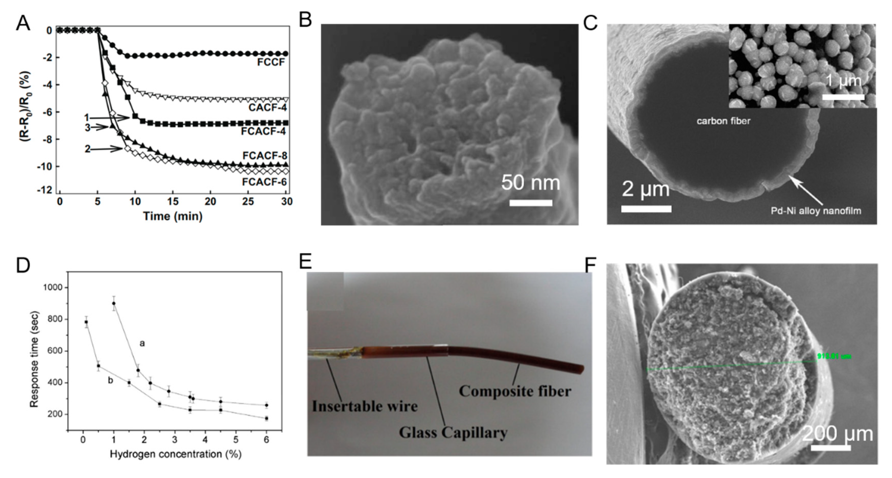
- Ou, Y.J.; Si, W.W.; Yu, G.; Tang, L.L.; Zhang, J.; Dong, Q.Z. Nanostructures of Pd–Ni alloy deposited on carbon fibers for sensing hydrogen. J. Alloy. Compd. 2013, 569, 130–135. [Google Scholar] [CrossRef]
- Prasad, B.B.; Kumar, D.; Madhuri, R.; Tiwari, M.P. Nonhydrolytic Sol–Gel derived imprinted polymer–multiwalled carbon nanotubes composite fiber sensors for electrochemical sensing of uracil and 5-fluorouracil. Electrochim. Acta 2012, 71, 106–115. [Google Scholar] [CrossRef]
- Wu, Z.; Chen, L.; Shen, G.; Yu, R. Platinum nanoparticle-modified carbon fiber ultramicroelectrodes for mediator-free biosensing. Sens. Actuators B Chem. 2006, 119, 295–301. [Google Scholar] [CrossRef]
- Doğru, E.; Erhan, E.; Arikan, O.A. The using capacity of carbon fiber microelectrodes in DNA biosensors. Electroanalysis 2017, 29, 287–293. [Google Scholar] [CrossRef]
- Gallo, G.J.; Thostenson, E.T. Electrical characterization and modeling of carbon nanotube and carbon fiber self-sensing composites for enhanced sensing of microcracks. Mater. Today Commun. 2015, 3, 17–26. [Google Scholar] [CrossRef]
- Ahmed, S.; Thostenson, E.T.; Schumacher, T.; Doshi, S.M.; McConnell, J.R. Integration of carbon nanotube sensing skins and carbon fiber composites for monitoring and structural repair of fatigue cracked metal structures. Compos. Struct. 2018, 203, 182–192. [Google Scholar] [CrossRef]
- Kalashnyk, N.; Faulques, E.; Thomsen, J.S.; Jensen, L.R.; Rauhe, J.C.M.; Pyrz, R. Strain sensing in single carbon fiber epoxy composites by simultaneous in-situ raman and piezoresistance measurements. Carbon 2016, 109, 124–130. [Google Scholar] [CrossRef]
- Vaidya, S.; Allouche, E.N. Strain sensing of carbon fiber reinforced geopolymer concrete. Mater. Struct. 2011, 44, 1467–1475. [Google Scholar] [CrossRef]
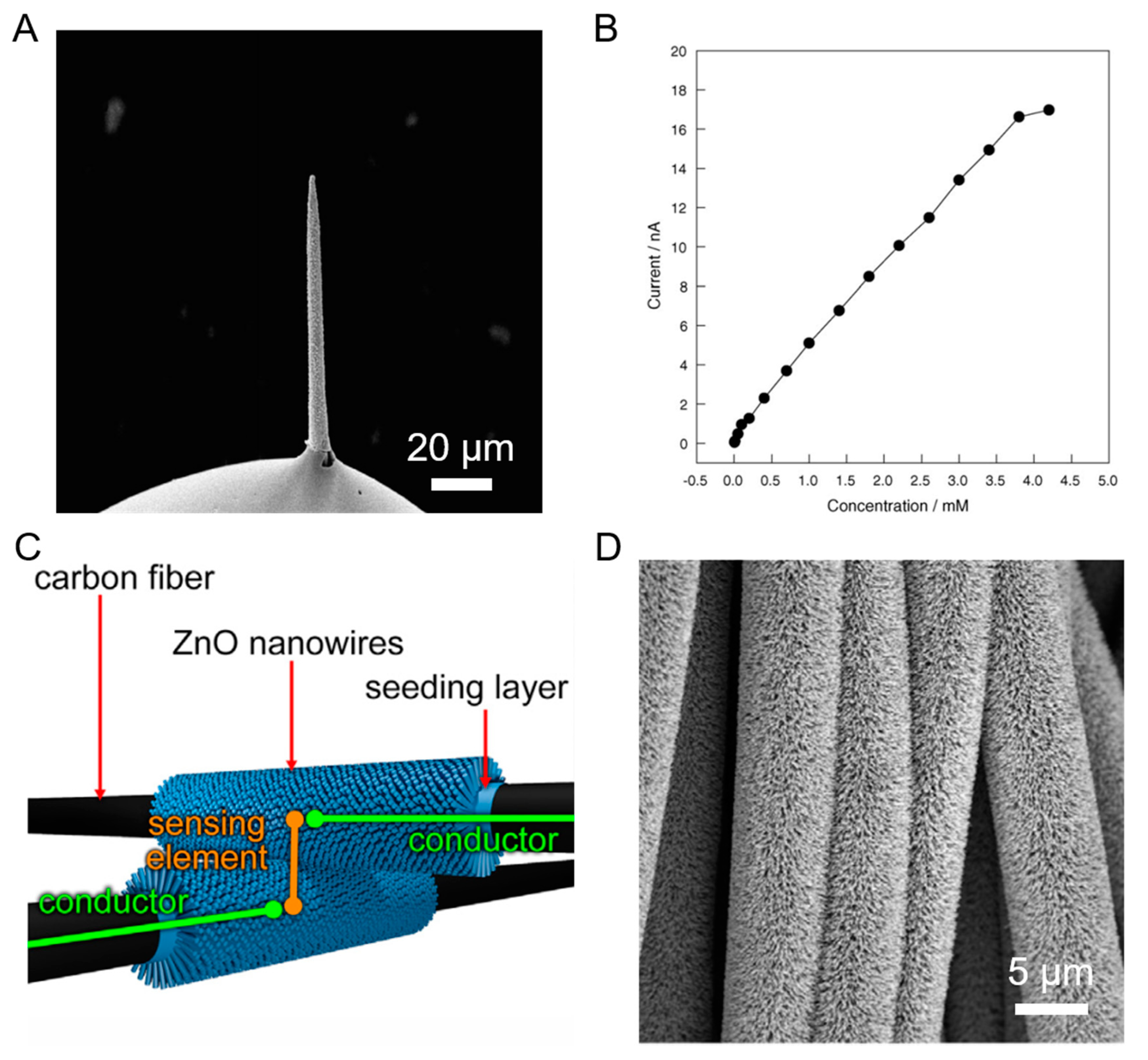
- Calestani, D.; Villani, M.; Culiolo, M.; Delmonte, D.; Coppedè, N.; Zappettini, A. Smart composites materials: A new idea to add gas-sensing properties to commercial carbon-fibers by functionalization with Zno nanowires. Sens. Actuators B Chem. 2017, 245, 166–170. [Google Scholar] [CrossRef]
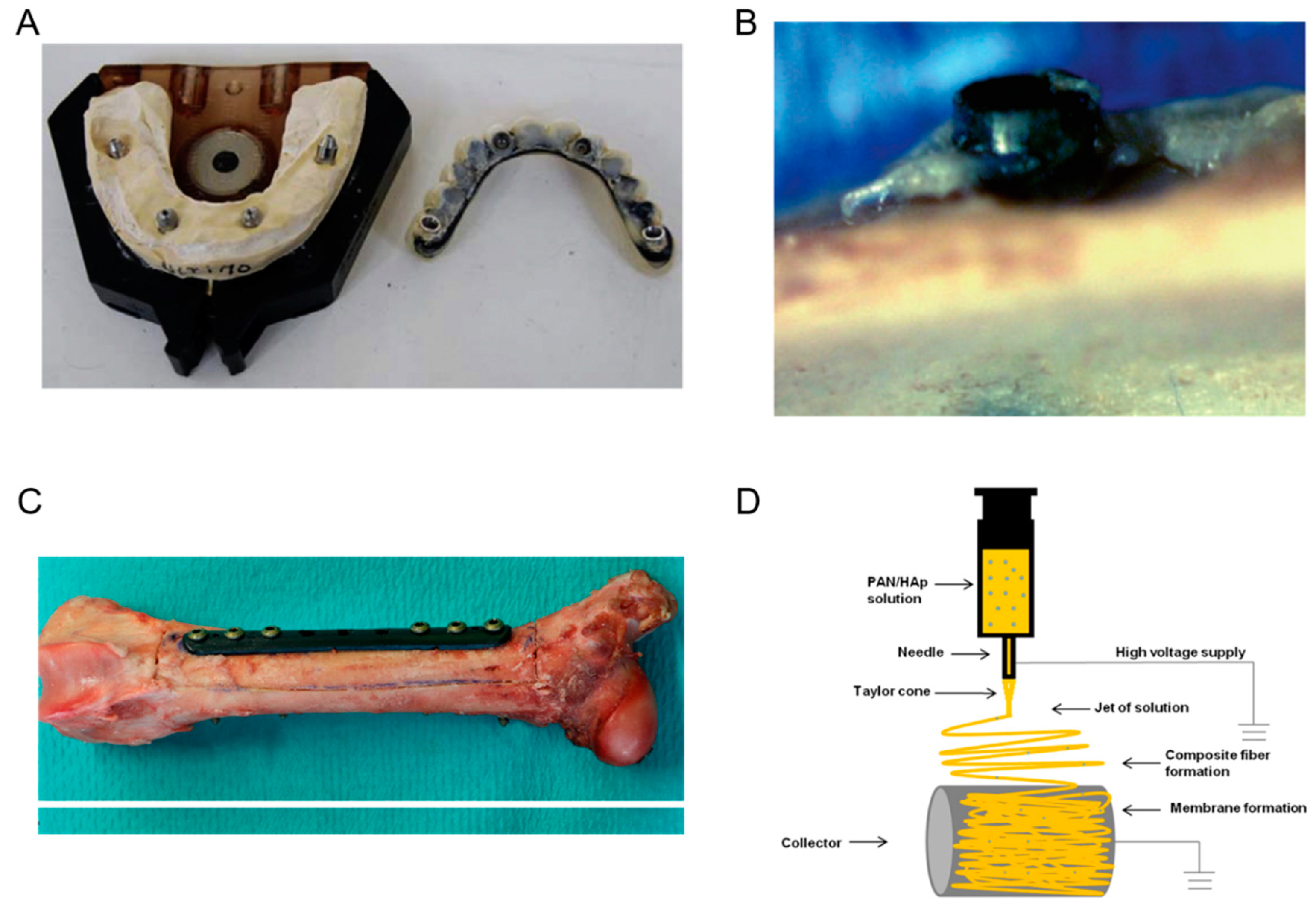
- Menini, M.; Pesce, P.; Pera, F.; Barberis, F.; Lagazzo, A.; Bertola, L.; Pera, P. Biological and mechanical characterization of carbon fiber frameworks for dental implant applications. Mater. Sci. Eng. C 2017, 70, 646–655. [Google Scholar] [CrossRef]
- Peterson, R.C. Bisphenyl-polymer/carbon-fiber-reinforced composite compared to titanium alloy bone implant. Int. J. Polym. Sci. 2011, 168924. [Google Scholar] [CrossRef]
- Laux, C.J.; Villefort, C.; Ehrbar, S.; Wilke, L.; Guckenberger, M.; Muller, D.A. Carbon fiber/polyether ether ketone (CF/PEEK) implants allow for more effective radiation in long bones. Materials 2020, 13, 1754. [Google Scholar] [CrossRef] [PubMed]
- Rajzer, I.; Kwiatkowski, R.; Piekarczyk, W.; Binias, W.; Janicki, J. Carbon nanofibers produced from modified electrospun PAN/hydroxyapatite precursors as scaffolds for bone tissue engineering. Mater. Sci. Eng. C 2012, 32, 2562–2569. [Google Scholar] [CrossRef]
- Huang, W.-Y.; Yeh, C.-L.; Lin, J.-H.; Yang, J.-S.; Ko, T.-H.; Lin, Y.-H. Development of fibroblast culture in three-dimensional activated carbon fiber-based scaffold for wound healing. J. Mater. Sci. Mater. Med. 2012, 23, 1465–1478. [Google Scholar] [CrossRef] [PubMed]
- Naskar, D.; Ghosh, A.K.; Mandal, M.; Das, P.; Nandi, S.K.; Kundu, S.C. Dual growth factor loaded nonmulberry silk fibroin/carbon nanofiber composite 3D scaffolds for in vitro and in vivo bone regenration. Biomaterials 2017, 136, 67–85. [Google Scholar] [CrossRef]
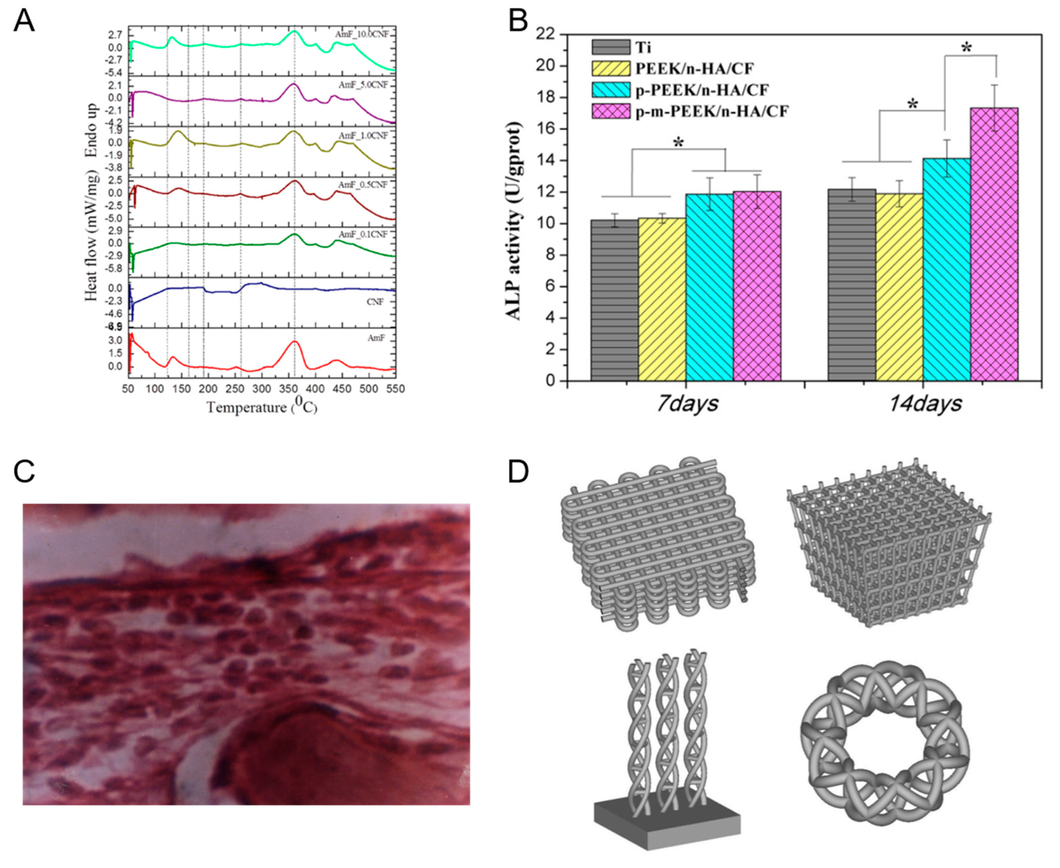
- Xu, A.; Liu, X.; Gao, X.; Deng, F.; Deng, Y.; Wei, S. Enhancement of osteogenesis on micro/nano-topographical carbon fiber-reinforced polyetheretherketone-nanohydroxyapatite biocomposite. Mater. Sci. Eng. C 2015, 48, 592–598. [Google Scholar] [CrossRef]
- Srivastava, V.K.; Rastogi, A.; Goel, S.C.; Chukowry, S.K. Implantation of tricalcium phosphate-polyvinyl alcohol filled carbon fibre reinforced polyester resin composites into bone marrow of rabbits. Mater. Sci. Eng. A 2007, 448, 335–339. [Google Scholar] [CrossRef]
- Prokić, B.B.; Bačić, G.; Prokić, B.; Kalijadis, A.; Todorović, V.; Puškaš, N.; Vidojević, D.; Laušević, M.; Laušević, Z. In vivo MRI biocompatibility of functionalized carbon fibers in reaction with soft tissues. Acta Vet. 2012, 62, 683–696. [Google Scholar] [CrossRef]
- Ruiz, J.P.G.; Lantada, A.D. 3D printed structures filled with carbon fibers and functionalized with mesenchymal stem cell conditioned media as in vitro cell niches for promoting chondrogenesis. Materials 2018, 11, 23. [Google Scholar] [CrossRef]
- Pesce, P.; Lagazzo, A.; Barbeis, F.; Repetto, L.; Pera, F.; Baldi, D.; Menini, M. Mechanical characterisation of multi vs. uni-directional carbon fiber frameworks for dental implant applications. Mater. Sci. Eng. C 2019, 102, 186–191. [Google Scholar] [CrossRef]
- Wan, Y.; Zuo, G.; Yu, F.; Huang, Y.; Ren, K.; Luo, H. Preparation and mineralization of three-dimensional carbon nanofibers from bacterial cellulose as potential scaffolds for bone tissue engineering. Surf. Coat. Technol. 2011, 205, 2938–2946. [Google Scholar] [CrossRef]
- Deng, Y.; Zhou, P.; Liu, X.; Wang, L.; Xiong, X.; Tang, Z.; Wei, J.; Wei, S. Preparation, characterization, cellular response and in vivo osseointegration of polyetheretherketone/nano-hydroxyapatite/carbon fiber ternary biocomposite. Colloids Surf. B Biointerfaces 2015, 136, 64–73. [Google Scholar] [CrossRef] [PubMed]
- Chen, X.; Wu, Y.; Ranjan, V.D.; Zhang, Y. Three-dimensional electrical conductive scaffold from biomaterial-based carbon microfiber sponge with bioinspired coating for cell proliferation and differentiation. Carbon 2018, 134, 174–182. [Google Scholar] [CrossRef]
- Araoye, I.B.; Chodaba, Y.E.; Smith, K.S.; Hadden, R.W.; Shah, A.B. Use of intramedullary carbon fiber nail in hindfoot fusion: A small cohort study. Foot Ankle Surg. 2019, 25, 2–7. [Google Scholar] [CrossRef] [PubMed]


| S.No. | Active Materials | Output Performance | Reference |
|---|---|---|---|
| 1. | CNT/GNR fiber | Voc = 0.846 V | [37] |
| Jsc = 13.49 mA cm−2 | |||
| FF = 56% | |||
| = 6.39% | |||
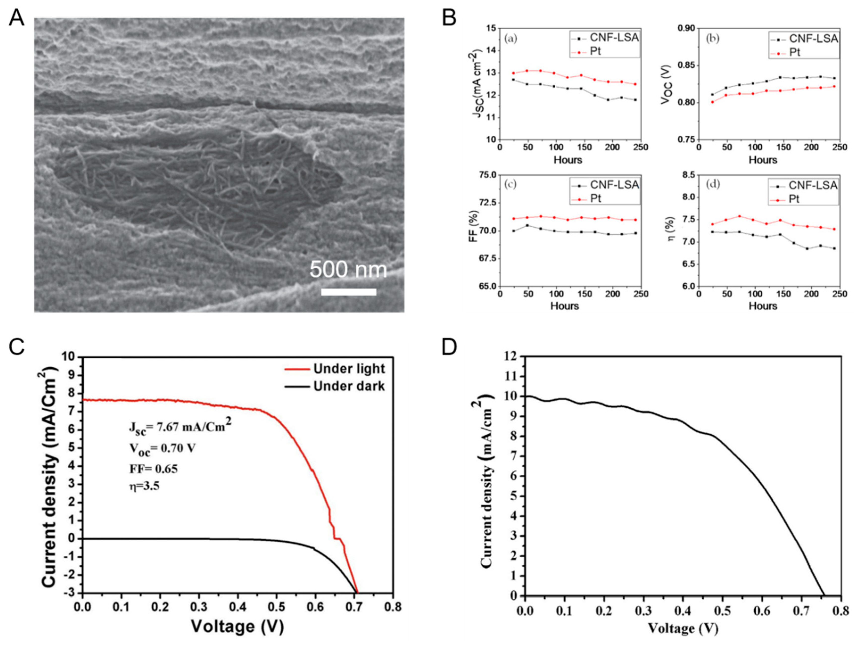
| 2. | CNF-LSA | Voc = 0.779 V | [38] |
| Jsc = 12.6 mA cm−2 | |||
| FF = 55.2% | |||
| = 5.4% | |||
| 3. | CuNi NPs-CNF | Voc = 0.7 V | [39] |
| Jsc = 7.67 mA cm−2 | |||
| FF = 65% | |||
| = 3.5% | |||
| 4. | Co-TiC NPs-CNF | Voc = 0.758 V | [40] |
| Jsc = 9.98 mA cm−2 | |||
| FF = 50.7% | |||
| = 3.87% | |||
| 5. | Hollow activated CNF | Voc = 0.73 V | [41] |
| Jsc = 14.5 mA cm−2 | |||
| FF = 62% | |||
| = 6.58% | |||
| 6. | NiCo2S4-CF | Voc = 0.63 V | [42] |
| Jsc = 17.78 mA cm−2 | |||
| FF = 56% | |||
| = 6.31% | |||
| 7. | PtNPs/VGCF | Voc = 0.55 V | [43] |
| Jsc = 15.47 mA cm−2 | |||
| FF = 45% | |||
| = 3.79% | |||
| 8. | CoNi2S4 nanoribbon-CF | Voc = 0.68 V | [44] |
| Jsc = 15.3 mA cm−2 | |||
| FF = 67.7% | |||
| = 7.03% | |||
| 9. | TiO2 NR-CF | Voc = 0.63 V | [45] |
| Jsc = 2.57 mA cm−2 | |||
| FF = 47% | |||
| = 0.76% | |||
| 10. | Pt/CF | Jsc = 15.52 mA cm−2 | [46] |
| FF = 68% | |||
| = 8.97% |
© 2020 by the authors. Licensee MDPI, Basel, Switzerland. This article is an open access article distributed under the terms and conditions of the Creative Commons Attribution (CC BY) license (http://creativecommons.org/licenses/by/4.0/).
Share and Cite
Das, C.M.; Kang, L.; Yang, G.; Tian, D.; Yong, K.-T. Multifaceted Hybrid Carbon Fibers: Applications in Renewables, Sensing and Tissue Engineering. J. Compos. Sci. 2020, 4, 117. https://doi.org/10.3390/jcs4030117
Das CM, Kang L, Yang G, Tian D, Yong K-T. Multifaceted Hybrid Carbon Fibers: Applications in Renewables, Sensing and Tissue Engineering. Journal of Composites Science. 2020; 4(3):117. https://doi.org/10.3390/jcs4030117
Chicago/Turabian StyleDas, Chandreyee Manas, Lixing Kang, Guang Yang, Dan Tian, and Ken-Tye Yong. 2020. "Multifaceted Hybrid Carbon Fibers: Applications in Renewables, Sensing and Tissue Engineering" Journal of Composites Science 4, no. 3: 117. https://doi.org/10.3390/jcs4030117
APA StyleDas, C. M., Kang, L., Yang, G., Tian, D., & Yong, K.-T. (2020). Multifaceted Hybrid Carbon Fibers: Applications in Renewables, Sensing and Tissue Engineering. Journal of Composites Science, 4(3), 117. https://doi.org/10.3390/jcs4030117