Article

The Use of Conductive Polymers Embedded Macro Porous Pei and Ionic Liquid Form of Pei Cryogels for Potential Conductometric Sensor Application to CO2

by
Sahin Demirci
1 and
Nurettin Sahiner
1,2,3,*
1
Canakkale Onsekiz Mart University, Faculty of Science and Arts, Department of Chemistry & Nanoscience and Technology Research and Application Center (NANORAC), Terzioglu Campus, 17100 Canakkale, Turkey
2
Department of Chemical and Biomolecular Engineering, University of South Florida, Tampa, FL 33620, USA
3
Department of Ophthalmology, Morsani College of Medicine, University of South Florida, 12901 Bruce B. Downs Blvd, MDC21, Tampa, FL 33612, USA
*
Author to whom correspondence should be addressed.
J. Compos. Sci. 2020, 4(1), 27; https://doi.org/10.3390/jcs4010027
Submission received: 19 February 2020 / Revised: 10 March 2020 / Accepted: 11 March 2020 / Published: 13 March 2020
(This article belongs to the Special Issue Recent Advances in Conductive Polymer Composites)

Abstract

:
Polyethyleneimine (PEI) cryogels with interconnected superporous morphology were synthesized via the cryopolymerization technique. Then, conductive polymers, poly(Aniline) (PANi), poly(Pyrrole) (PPy), and poly(Thiophene) (PTh) were prepared within these PEI cryogels. Then, the conductive polymer embedding PEI composites’ characterization was carried morphologically using scanning electron microscope (SEM) by means of Fourier Transform Infrared Radiation (FT-IR) spectrometer, and by means of electrical conductivity measurements using an electrometer. Among all the prepared cryogel conductive polymer composites, the highest value in terms of conductivity was determined for PEI/PANi cryogel composites with 4.80 × 10⁻³ S.cm−1. Afterward, to prepare polymeric ionic liquid (PIL) forms of PEI and PEI/PANi composites. To assess the effect of anions on the conductivities of the prepared composites, PEI-based cryogels were anion ex-changed after protonation with HCl by treatment of aqueous solutions of sodium dicyanamide (Na+[N(CN)2]), ammonium hexafluorophosphate (NH4+[PF6]), sodium tetrafluoroborate (Na+[BF4]), and potassium thiocyanate (K+[SCN]), separately. Furthermore, PEI-based cryogel composites and their PIL forms were tested as a sensor for CO2 gas. The higher conductivity changes were observed on bare PEI cryogel and PEI+[BF4] PIL cryogels with 1000-fold decrease on conductivity upon 240 min CO2 exposure. The sensitivity and recovery percent of bare PEI and PEI+[BF4] PIL cryogels were shown almost the same with a two-fold decrease in the presence of 0.009 mole of CO2 gas, and approximately 30% recovery after the fifth consecutive reuse.

Graphical Abstract

1. Introduction

Carbon dioxide (CO2) exist in the mixture of atmospheric gas and fossil fuels (coal, natural gas, petroleum, and derivatives) as a result of industrial discharge and forest fires and natural disasters. Among the thermal power plants, oil refineries, and petrochemical plants, hydrogen and cement plants are the major producers of CO2 [1]. The contribution of CO2 is 80%–85% in the atmosphere, derived from fossil fuels, and about 15%–20% from the respiration of living things and the decomposition of organic matter from microscopic organisms [2]. In addition to the rapid increase of fossil fuel use, the destruction of forests and vegetation plankton, which consume tons of CO2 during photosynthesis, have reached the highest level of CO2 in the atmosphere over the past 160,000 years and analyses project that this increase will continue [3]. The emission of produced CO2 gas into the world atmosphere is an international issue due to the influence of greenhouse gases with this uncontrolled emission that the Kyoto protocol tried to limit. Therefore, the selective separation of CO2 from gas mixtures, detection of CO2, and harmless storage "CO2 sequestration" is considered of paramount significance [4].
Current approaches in CO2 sensing, including spectrophotometry [5,6], solid-electrolyte electrochemical sensors [7], and semiconductor metal oxide-based sensors [8], have disadvantages such as cost, volume/size, or high energy consumption and so on. Researchers have been seeking to discover new methods to overcome these disadvantages in CO2 detection methods. Following Severinghaus’s approach, some types of alkyl amine were used as CO2 determination layers, producing carbonic acid and carbamates contributing to the pH change in the amine phase [9]. The reaction or interaction between amine groups and CO2 occurs in three possible ways such as the acid-based reaction, decomposition, and base-catalyzed CO2 hydration, depending on the type of amine groups (primary, secondary, or tertiary) and relative humidity [10]. Therefore, it is a practical approach to consider PEI as it contains all different types of amines (primary, secondary, and tertiary amines) to use CO2 interacting material as composite polymeric sensing applications. Additionally, the branched structure of PEI can provide an intermedia to the acid-base reaction, structurally helping to realize the reaction that acidifies amines for high CO2 loading capacity in base catalyzed hydration and results in good amine recovery [10].
In this study, PEI cryogels with superporous morphology were used as a template for in situ conductive PANi, PPy, and PTh polymer syntheses. In addition, PEI cryogels were turned into the corresponding IL forms by employing anion-exchange reactions or the protonated PEI at room temperature. The aqueous solutions of Na+[N(CN)2], NH4+ [PF6], Na+[BF4], and K+[SCN] were used as an anion source in the preparation of PIL PEI cryogels. Next, this PIL PEI cryogels were also used as a template in conductive PANi synthesis. The potential sensor application of prepared PEI, PEI/PANi, PEI/PPy, and PEI/PTh cryogel composites were investigated based on electrical conductivity values after CO2 gas exposure at various times at 200 mL/min flow rate. The potential sensor application of PEI-based PIL cryogels were also tested, and the sensitivity and percent recovery (to attain the % initial sensitivity) were investigated.

2. Materials and Methods

2.1. Materials

Polyethyleneimine (PEI, 50 wt% soln. in water, Mn: 1200, Mn:1800, and Mn:60,000, d:1.08, Sigma Aldrich, St. Louis, MO, USA), glycerol diglycidyl ether (GDE ≤ 100%, Sigma Aldrich, St. Louis, MO, USA) were used in the synthesis of PEI cryogels. Hydrochloric acid (HCl, 36.5–38%, Sigma Aldrich, St. Louis, MO, USA) were used for the protonation of PEI cryogels. Sodium dicyanamide (Na+[N(CN)2], 96%, Aldrich, St. Louis, MO, USA), ammonium hexafluorophosphate (NH4+[PF6], 99%, Aldrich, St. Louis, MO, USA), sodium tetrafluoroborate (Na+[BF4], 97%, Merck, Darmstadt, Germany), and potassium thiocyanate (K+[SCN], 99%, Merck, Darmstadt, Germany) were used for preparation of polymeric ionic liquid PEI cryogels as an anion source. Aniline (ANi, 99%, Sigma-Aldrich, St. Louis, MO, USA), pyrrole (Py, 98%, Aldrich, St. Louis, MO, USA), and thiophene (Th, 99%, Aldrich, St. Louis, MO, USA) were used as monomers in the synthesis of the corresponding conductive polymers. Ammonium persulfate (APS, 98%, Sigma-Aldrich, St. Louis, MO, USA), and iron (III) chloride hexahydrate (FeCl3.6H2O, 98%, Acros, Carlsbad, CA, USA) were used as an initiator for in situ synthesis of conductive polymers. Chloroform (CH3Cl, 99%, Riedel de Haen, Seelze, Germany) was used for in situ synthesis of PTh. The CO2 gas tank was purchased from local vender, Turkey. Pure ethanol (99.9%, Sigma-Aldrich, St. Louis, MO, USA) was used in washing of cryogels and throughout the experiments.

2.2. Synthesis of Macro Porous PEI and PIL PEI Cryogels

The epoxy-amine reaction at cryogenic conditions was exploited in the synthesis of PEI cryogels as reported earlier by our group and the preparation of PIL forms of PEI cryogels was carried out via anion exchange reactions [11]. Additionally, the details about synthesis of PEI cryogels, and preparation of PIL forms of PEI cryogels are given in Supporting Information.

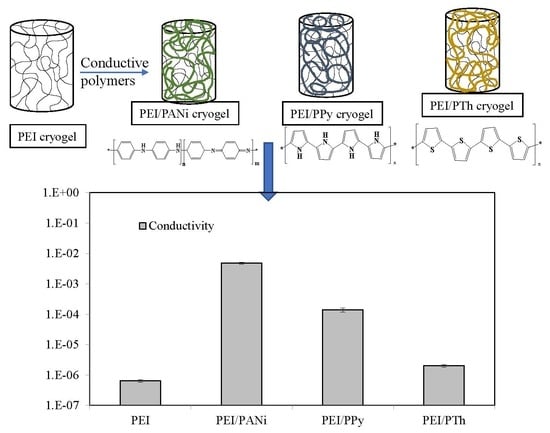
2.3. In situ Preparation of Conductive Polymers within PEI Cryogels

In the in-situ synthesis of PANi, PPy, and PTh, conductive polymers within super macroporous PEI cryogels was carried out according to earlier reports [12,13]. In brief, PEI-based cryogels were placed into ANi, Py, and Th monomers in liquid form to load these monomers into PEI cryogels. Then, the PEI cryogels containg ANi, Py, and Th monomers were placed into initiator systems for the polymerization within PEI cryogel pores. The details about in situ synthesis of PAN, PPy, and PTh conductive polymers within PEI cryogels are also provided in Supporting Information.

2.4. Instruments

The details about used instruments for the characterization and sensor application are given in the Supporting Information.

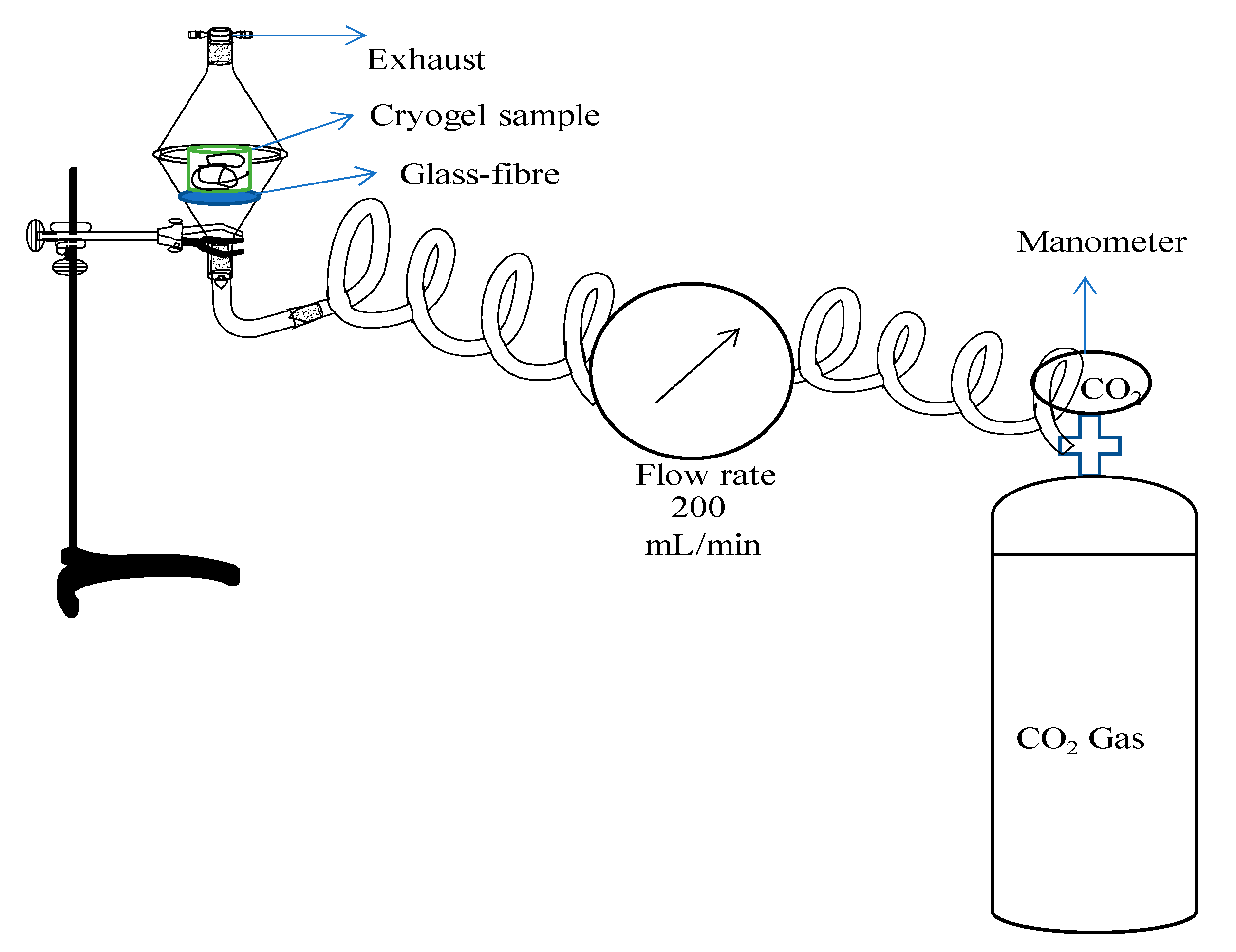
2.5. Conductometric Sensor Application of PEI-Based Composites against CO2 Gas

PEI-based cryogels and their PANi, PPy, and PTh conductive polymer composites, and also PIL PEI cryogels were tested as a sensor against CO2 gas by means electrical conductivity changes upon CO2 exposure. The PEI-based cryogels were exposed to 200 mL/min flow rate of CO2 gas for 30, 60, 120, and 240 min, and the difference on conductivities before and after CO2 treatments were measured. In the sensitivity studies, the exposure of CO2 gas with a 200 mL/min flow rate for 1, 5, 15, 30, 45, 60, 75, 90, 105, 120, and 240 min were also carried out. Furthermore, the recovery percentage studies were done by thermal methods in which 240 min of CO2 gas treated PEI-based cryogels, which were placed into an oven at 50 °C for 60 min, and re-exposed to CO2 gas again at the same conditions (200 mL/min flow rate). These cycles were repeated for five times by measuring the conductivity in between every cycle.

3. Results

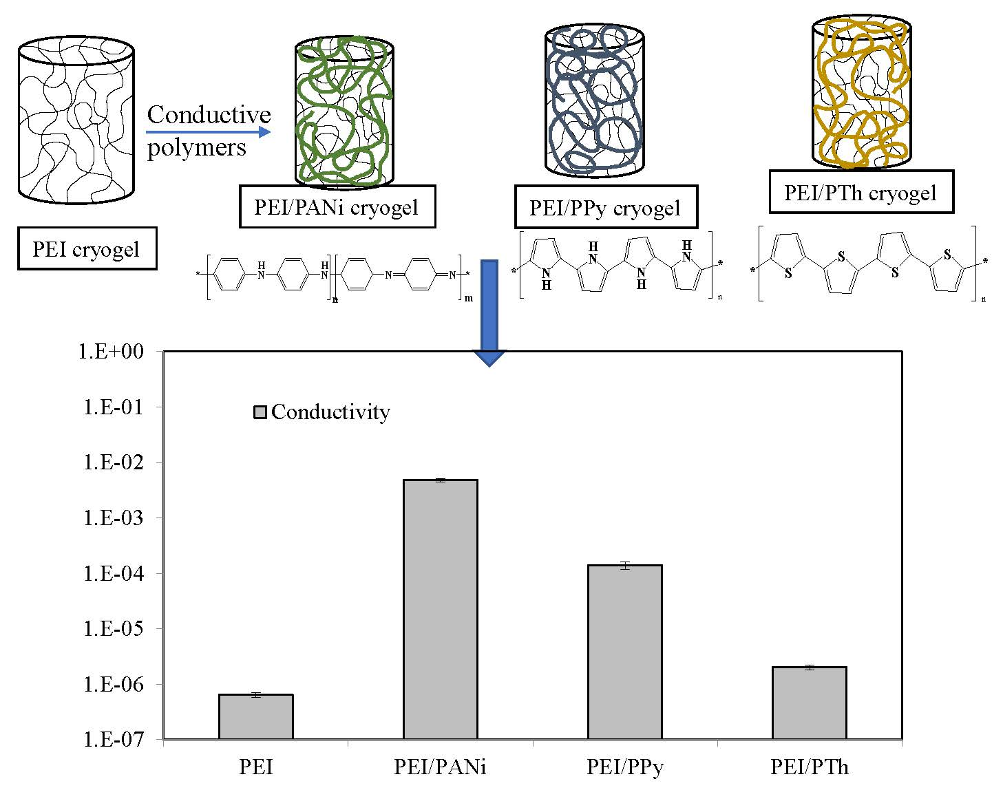
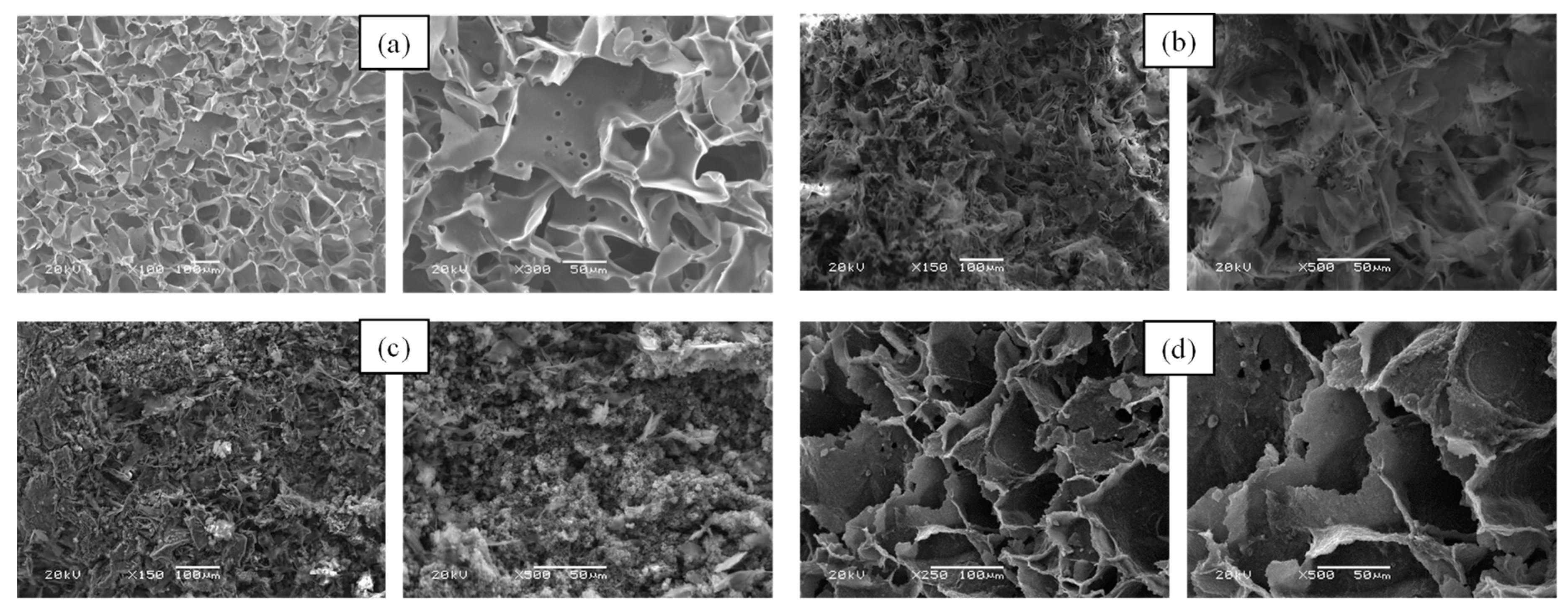
3.1. Synthesis and Characterization of PEI Cryogel/Conductive Polymer Composites

As mentioned, PEI cryogels were prepared by using epoxy-amine reaction at cryogenic conditions (T = −18 °C). The linking of PEI chains with GDE molecules generated supermacroporous PEI cryogels with interconnected pores [11]. The preparation of the IL forms of PEI cryogels and their use in adsorption/separation of some organic dyes were also reported in detail [11]. Among the various molecular weights of branched PEI, Mn: 1800 was found to possess better mechanical strength than the others [11]. Therefore, PEI cryogels that were prepared by using Mn: 1800 g/mole was used as a template for in situ conductive polymers, e.g., PANi, PPy, and PTh synthesis. The schematic presentation of PEI cryogels and then the in situ conductive polymers syntheses within PEI cryogel as composites is illustrated in Figure S1 [12,13]. Before polymerization of ANi, Py, and Th, known weight PEI cryogel pieces was placed into 10 mL of corresponding monomers for about 30 min to load monomers into the pores of PEI cryogels. Then, the ANi loaded PEI cryogels were weighed again to determine the loaded amount of ANi into PEI cryogels and then placed into a 1:1.25 (APS:ANi) mole ratio APS containing 1 M HCl solution to initiate the in situ polymerization of ANi molecules within PEI cryogels under a constant stirring rate at 250 rpm for about 15 min. The Py and Th loaded PEI cryogels were also similarly placed into 0.5 M 250 mL FeCl3 solution in DI water at room temperature for 2 h, and in 0.3 M 100 mL FeCl3 solution in chloroform at 65 °C for 16 h to initiate the corresponding in situ polymerization of Py and Th within PEI cryogels, respectively. After that, the PEI conductive polymer containing cryogels were washed with DI water exhaustively and dried in oven at 50 °C for 12 h.
The FT-IR spectra of PEI/PANi, PEI/PPy, and PEI/PTh cryogel conductive polymer composites are given in Figure S2 to confirm the synthesis of conductive PANi, PPy, and PTh polymers within PEI cryogels. From the FT-IR spectrum, the most notable peaks of PEI cryogel were observed as N-H stretching at 3276 cm−1, C-H stretching at 2951 and 2842 cm−1, and C-N-C stretching peak at 1300 cm−1. Additionally, upon crosslinking PEI with GDE, the peaks for O-H bending and C-O stretching from secondary alcohols obtained from the reactions of amines with epoxies were observed at 1112 and 1043 cm−1, respectively. Moreover, the observed peaks at 1570 cm−1 match the benzenoic-quinonic nitrogen vibration, at 1486 cm−1 aromatic C-C peaks, at 1305 cm-1 aromatic amine peak, and C-N-C peaks at 1145 cm−1 belonging to PANi conductive polymers [14] conforming the PEI/PANi cryogel composites. Similarly, FT-IR spectrum of PEI/PPy cryogel composites were also shown characteristic peaks of PPy such as =C–H band in-plane vibrations at 1360 cm−1, and N–C stretching vibrations at 1228 cm−1, and the peaks, to the presence of PPy observed 789 and 1021 cm−1, and =C–H assigned to the out of plane stretching vibration at 923 cm−1 [15]. Furthermore, the characteristic peaks of PTh were also seen in FT-IR spectrum of PEI/PTh cryogel composites at 1324 and 1424 cm−1 associated with C-H in-plane bending vibrations of Th molecules, and peak at 789 cm−1 for α-α connection between Th molecules, which was generated due to the PTh structure. This confirms the in situ synthesis of PTh within the PEI cryogel [16].
The SEM images of PEI/conductive polymer cryogel composites are demonstrated in Figure 1. In Figure 1a, the clear and open pores of bare PEI cryogels were clearly seen with varied pore sizes between 1–50 µm.
On the other hand, it is apparently seen from SEM images of PEI/PANi, PEI/PPy, and PEI/PTh cryogel composites in Figure 1b–d the existence of conductive polymers of PANi, PPy, and PTh, respectively, within PEI cryogels by filing and/or plugging the pores and pore walls of PEI cryogels with these guest conductive polymers. The extent of in situ synthesized conductive PANi, PPy, and PTh polymers within PEI cryogels were calculated gravimetrically and results were summarized in Table S1, as 5.9 ± 0.4 g of PANi/g of PEI cryogel, 5.1 ± 0.1 g of PPy/g of PEI cryogel, and 3.2 ± 0.3 g of PTh/g of PEI cryogel.

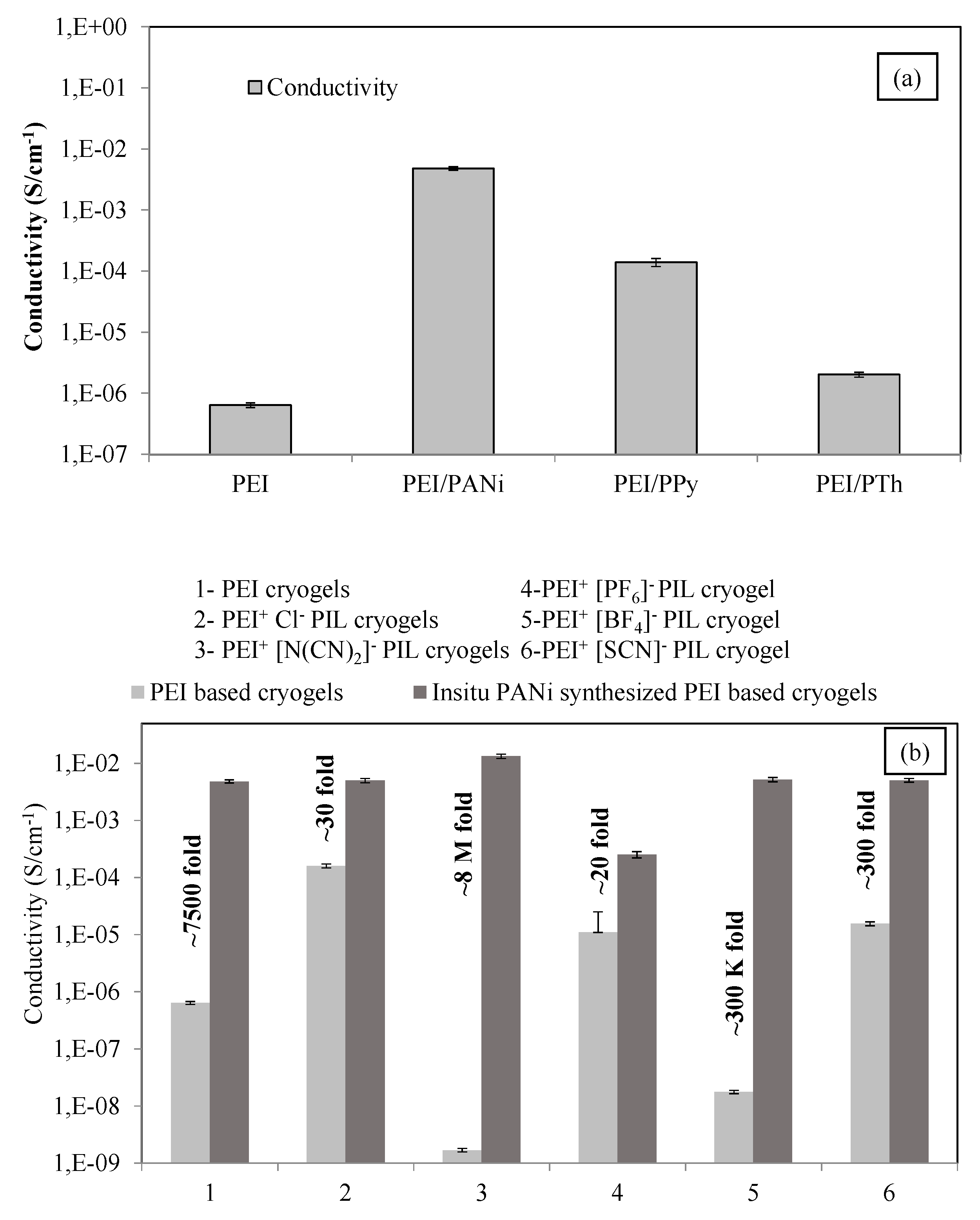
Conductivity Measurements

The electrical conductivity of PEI, PEI/PANi, PEI/PPy, and PEI/PTh cryogel composites were determined from ohmic region of I-V curves obtained using an electrometer. The schematic presentation of electrometer setup used in the conductivity measurements of PEI/conductive polymer cryogel composite are given in Figure S3. It was clearly seen from digital camera images that the white color of PEI cryogels turned to black upon situ synthesis conductive PANi and PPy polymers, and brown with the in-situ synthesis of conductive PTh polymers, respectively. The I-V curves from the conductivity measurements of PEI-based composite cryogels done by connecting the electrodes on carbon tape that glued on both sides of PEI-based cryogel composite cylinders. Then, the conductivity of a PEI-based cryogel composite were calculated from an ohmic region of I-V curves by using Equations (1) and (2).
V = I × R
σ = (1/R) × (l/A)
where ‘V’ is applied voltage, ‘I’ is current, ‘R’ is the bulk resistance, ‘σ’ is conductivity, ‘1/R’ is resistivity, ‘l’ is the thickness, and ‘A’ is the cross-sectional area of the sample.
The comparison of conductivity values of PEI, PEI/PANi, PEI/PPY, and PEI/PTh cryogel composites are presented in Figure 2a. The measured conductivity values are also summarized in Table S1. The conductivity of bare PEI cryogels were increased to 7500-, 220-, 3- folds after in situ synthesis of PANi, PPy, and PTh polymers, respectively. As the maximum extent of increase was observed for PEI/PANi cryogel, the conductive PANi polymer was chosen for IL forms of PEI cryogels.
PIL PEI cryogels were prepared in accordance with the literature and provided in Supplementary Information [11]. The protonated PEI cryogels by using 1 M HCl solution were treated with various IL agents such as Na+[N(CN)2], NH4+ [PF6], Na+[BF4], and K+[SCN] to exchange the anions to produce IL PEI cryogels with different anions. IL PEI cryogels were acquired by replacing Cl- anions on protonated PEI cryogels with dicyanamide ([N(CN)2]), hexafluorophosphate ([PF6]), tetrafluoroborate ([BF4]), and thiocyanate ([SCN]) anions. In addition, the anion exchange reactions were confirmed with FT-IR spectrum [11]. As mentioned previously, these IL PEI cryogels were used as a template for conductive PANi polymer and the results of the conductivity measurements of the prepared IL PEI-based cryogel composites were compared and illustrated in Figure 2b. Conductivity values were also summarized in Table S2. The conductivity of PEI cryogels increased to 1.64 × 10⁻⁴ ± 2.16 × 10⁻⁵ S.cm−1 from 6.40 × 10⁻⁷ ± 3.45 × 10⁻⁸ S.cm−1 with 250-fold increase after protonation with 1 M HCl solutions (IL forms of PEI). On the other hand, the conductivity of PEI+Cl cryogels also changed after treatment with IL forming agents and the conductivity values of 1.68 × 10⁻⁹ ± 3.21 × 10⁻⁵, 1.76 × 10⁻⁸ ± 1.26 × 10⁻⁹, 1.55 × 10⁻⁵ ± 2.85 × 10⁻⁶, and 1.09 × 10⁻⁵ ± 1.11 × 10⁻⁶ S cm−1 that are 100 000-, 10 000-, 10-, and 15-fold decrease for [N(CN)2], [PF6], [BF4], and [SCN] anions, respectively, were measured. Then, after the in-situ synthesis of the conductive PANi polymer within these IL PEI cryogel also show some increase on the measured conductivities of all PIL PEI cryogels. The conductivity of IL PEI cryogels were found to increase as 30-, 8 000 000-, 300 000-, 300-, and 20-fold upon in situ synthesis of conductive PANi polymers. The conductivity values of all PEI-based PIL and composite cryogels provide some appealing properties as they can be used to determine and/or sense various molecules because of not just functional groups of PEI but also the existence of diverse IL forming anions as well as the existence of conductive PANi within the pores of cryogels. There are few reports on the use of cryogels and cryogel/conductive polymer composites as a sensor to various gases or molecules [12,17,18].

3.2. Sensor Application

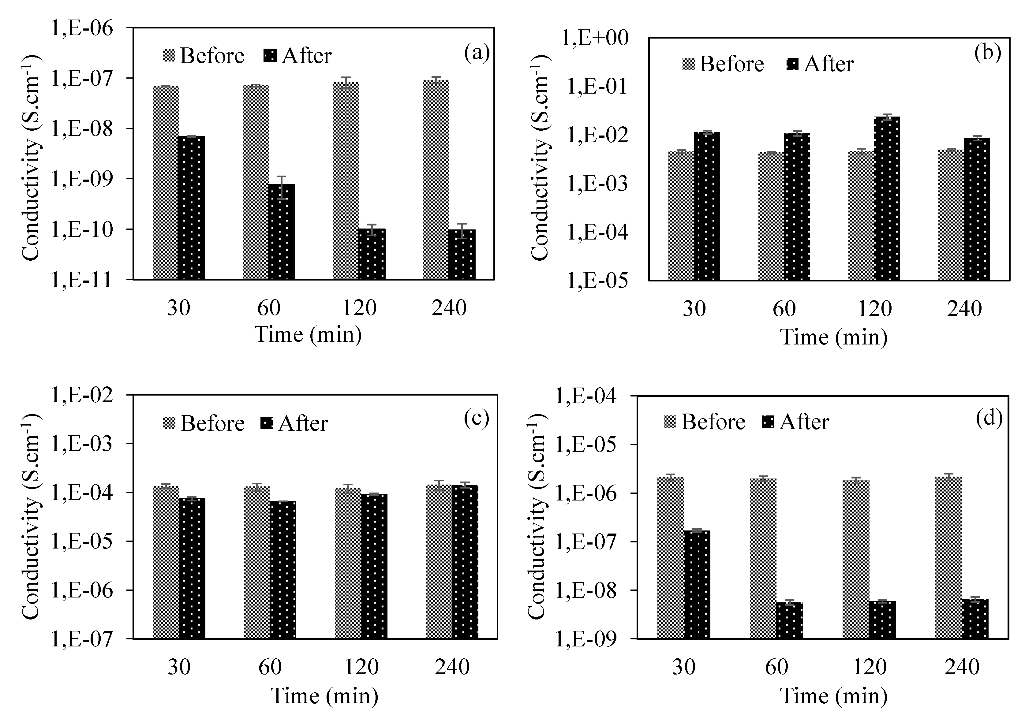
3.2.1. PEI/Conductive Polymer Cryogel Composites as Sensing Material

The potential usage of PEI for CO2 capture studies encouraged us to employ a PEI-based super porous structure for a potential sensor application. It was further known that IL materials along with PEI, e.g., composite cryogels for CO2 gas possess great potential [19,20,21]. Therefore, a basic experimental set-up, as shown in Figure 3, is arranged to measure the change in the conductivity of PEI cryogel before and after CO2 exposure.
As shown in the figure, the tube of CO2 gas was attached to a flow-meter to adjust flow rate of CO2 to 200 mL/min and then contact the-PEI based cryogels at this constant flow rate at various time intervals, e.g., 30, 60, 120, and 240 min. The change in the electrical conductivity of PEI and PEI/PANi, PEI/PPy, and PEI/PTh cryogel composites after CO2 treatment at various time intervals were measured and the corresponding graphs are given in Figure 4a–d, respectively.
The measured electrical conductivity values of PEI-based cryogel composites before and after exposure of CO2 gas at various exposure times are summarized in Table 1. The conductivity of PEI cryogels was found to decrease with the increase of CO2 exposure time of at least a 200 mL/min flow rate. The decrease in the extent of conductivity of PEI cryogels were increased with the rise of exposure time of CO2 as approximately 10-, 90-, 800-, and 1000-fold decrease for 30, 60, 120, and 240 min exposure of CO2 gas.
It is known that, with the exposure of CO2 to PEI cryogels results in carbamate formation, which reduce the overall electron donating effect and, therefore, upon carbamate formation, geometric deformations in the polymers’ layer may lead to reduction on the electrical conductivity [22]. The increase in the conductivity of PEI/PANi cryogel composites after exposure of CO2 gas as 2.5-, 2.5-, 5-, and 2-fold after 30, 60, 120, and 20 min of CO2 exposure. This increase on the conductivity of PEI/PANi cryogel composites can be explained with the formation of carbamates and carbonic acids that potentially dopes PANi leading to increased conductivity of PANi [23]. On the other hand, there was no observed significant change in the conductivity of PEI/PPy cryogel composites after 30, 60, 120, and 240 min of CO2 exposure. There is a slight change in conductivity as single digit results are reported for PEI/PPy composites upon 240 min of CO2 exposure. This can be perceived as unchanged. The conductivity values for PEI/PPy cryogel composites were measured as 1.44 × 10⁻⁴ ± 3.25 × 10⁻⁵, and 1.43 × 10⁻⁴ ± 1.87 × 10⁻⁵ before and after 240 min exposure of CO2 gas. It was reported that the saturation of PPy to CO2 gas was realized in 2 min exposure, and the conductivity of PPy was increased with more CO2 exposure [24]. On the other hand, there is no change observed in the conductivity of composite PPy with polyamide (PA) with more CO2 exposure. This was explained with very rapid, and reversible processing of doping and undoping of composites of PEI/PPy cryogel composites under CO2 gas exposure [24]. The conductivity of PEI/PTh cryogel composites also decreased as 12-, 350-, 310-, and 330-fold after the CO2 exposure times of 30, 60, 120, and 240 min, respectively. The higher conductivity change was observed for bare PEI cryogels with 10-, 90-, 800-, and 1000-fold decrease upon 30, 60, 120, and 240 min of CO2 exposure, respectively.

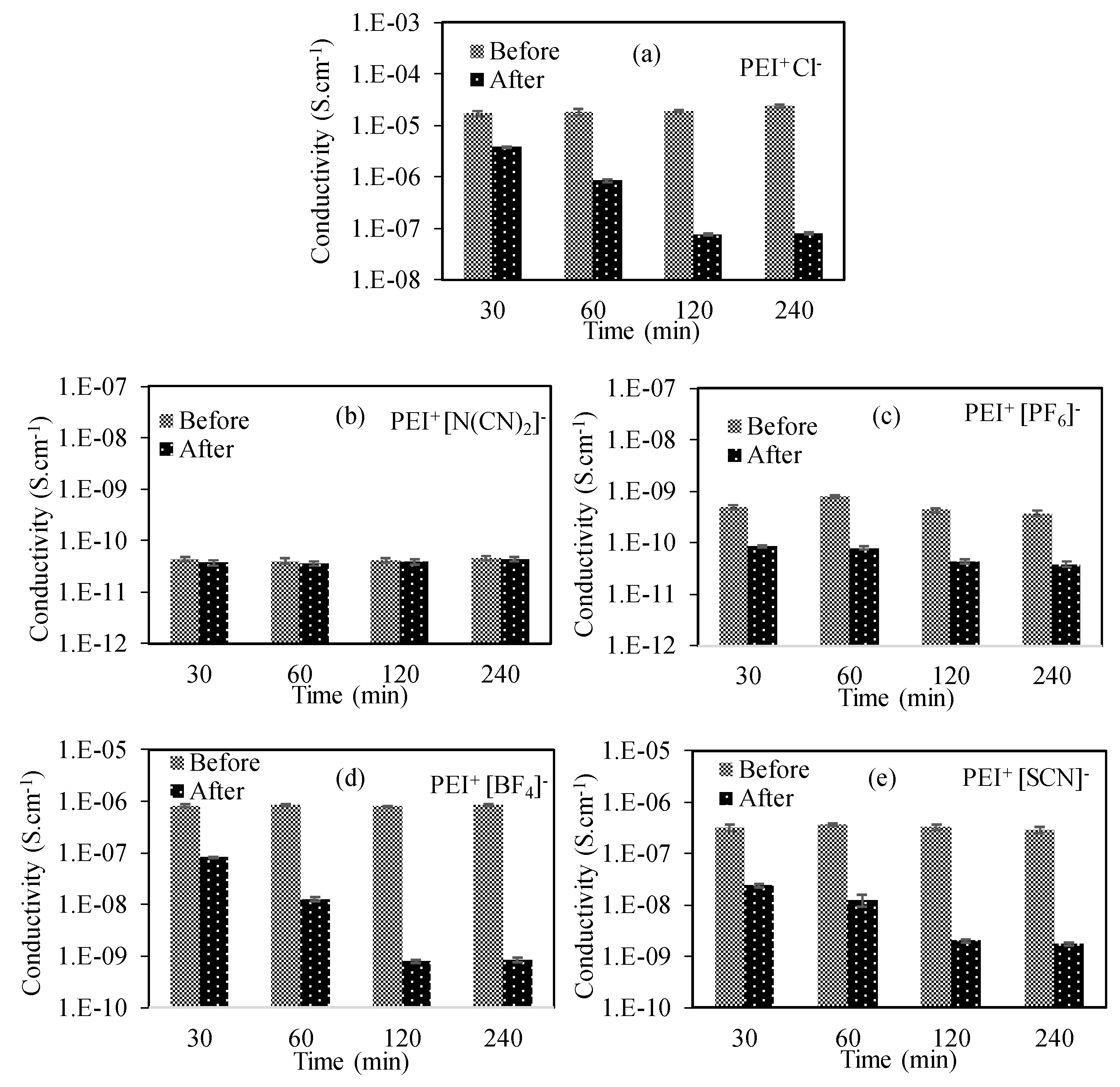
3.2.2. The Use of IL Forms of Pei Cryogels

The use of PIL materials on CO2 capture studies in the literature [25,26,27,28,29] urged us to study the change in the conductivity of conductive polymer containing IL PEI cryogels compounds after CO2 gas exposure. Therefore, IL forms of the PEI cryogel were also treated with CO2 for 30, 60, 120, and 240 min, and the change in their electrical properties was determined. The corresponding graphs of PEI+Cl, PEI+[N(CN)2], PEI+[PF6], PEI+[BF4], and PEI+[SCN] IL cryogels are given in Figure 5a–e, respectively, and summarized in Table 2. Form Figure 5a, it was observed that the conductivity value of PEI+ Cl cryogels decreased from 1.7 × 10⁻⁵ ± 1.8 × 10⁻⁶ to 3.8 × 10⁻⁶ ± 1.2 × 10⁻⁷, 1.8 × 10⁻⁵ ± 2.7 × 10⁻⁶ to 8.5 × 10⁻⁷ ± 6.2 × 10⁻⁸, 1.9 × 10⁻⁵ ± 8.9 × 10⁻⁷ to 7.7 × 10⁻⁸ ± 3.6 × 10⁻⁹, and 2.4 × 10⁻⁵ ± 1.5 × 10⁻⁶ to 8.0 × 10⁻⁸ ± 2.4 × 10⁻⁹ S.cm−1 by 30, 60, 120, and 240 min CO2 exposure, respectively. There are no observed significant changes in the conductivity of PEI+[N(CN)2], as shown in Figure 5b. The changes of the conductivity of PEI+[PF6] PIL cryogels are given in Figure 5c, and it is clear that the conductivity of PEI+[PF6] PIL cryogels decreased from 4.8 × 10⁻¹⁰ ± 4.6x10⁻¹¹ to 8.5 × 10⁻¹¹ ± 3.6 × 10⁻¹² S.cm−1 upon 30 min, and from 7.8 × 10⁻¹⁰ ± 3.9 × 10⁻¹¹ to 7.6 × 10⁻¹¹ ± 4.9 × 10⁻¹² S.cm−1 upon 60 min, and from 4.3 × 10⁻¹⁰ ± 4.2 × 10⁻¹² to 4.1 × 10⁻¹¹ ± 3.9 × 10⁻¹² S.cm−1 upon 120 min, and from 3.7 × 10⁻¹⁰ ± 4.2 × 10⁻¹¹ to 3.8 × 10⁻¹¹ ± 4.7 × 10⁻¹² S.cm−1 upon 240 min CO2 times.
Moreover, the conductivity changes on PEI+[BF4], and PEI+[SCN] PIL cryogels are given in Figure 5d and Figure 5e respectively, and it was observed that the conductivities of PEI+[BF4], and PEI+[SCN] PIL cryogel composites were decreased from 8.2 × 10⁻⁷ ± 6.5 × 10⁻⁸ and 3.2 × 10⁻⁷ ± 5.2×10⁻⁸ to 8.3 × 10⁻⁸ ± 3.2 × 10⁻⁹ and 2.4 × 10⁻⁸ ± 1.6 × 10⁻⁹ S.cm−1 for 30 min, and from 8.5 × 10⁻⁷ ± 3.6 × 10⁻⁸ and 2.9 × 10⁻⁷ ± 4.2 × 10⁻⁸ to 8.6 × 10⁻¹⁰ ± 8.5 × 10⁻¹¹ and 1.8 × 10⁻⁹ ± 1.4 × 10⁻¹⁰ S.cm−1 for 240 min exposure of CO2, respectively. As shown in Table 2, the order of higher change in the conductivities of IL forms PEI-based cryogels are bare PEI with 1000- fold, PEI+Cl PIL cryogel with 300-fold, PEI+[BF4] PEI PIL cryogels with 1000-fold, and PEI+[SCN] PIL cryogels with 165-fold were observed after 240 min CO2 gas exposure. As reported, the interaction between ILs and CO2 is strongly dependent on the solubility of CO2 in ILs, and the interaction between [N(CN)2] anions and CO2 is very low due to its basicity [30]. Therefore, this can explain the almost constant conductivity values of PEI+[N(CN)2] PIL cryogels against different CO2 exposure times or its independence from CO2 exposure time.
The reason for the constant conductivity value after 120 min exposure to CO2 can be explained with the saturation of PEI-based cryogels after 120 min exposure time for CO2 gas at a 200 mL/min flow rate. The saturation of cryogels with CO2 is preventing the change of conductivity as steady state is reached.
The FT-IR spectrum of bare PEI cryogels, PEI+Cl, PEI+[BF4], and PEI+[SCN] PIL cryogels were recorded before and after 240 min of CO2 exposure. The corresponding FT-IR spectra that were forced in the 1650–1850 cm−1 wavenumbers’ range shown in Figure S4a–d for bare PEI cryogels, PEI+Cl, PEI+[BF4], and PEI+[SCN] PIL cryogels, respectively. It was clearly seen from FT-IR spectrum of PEI-based cryogels after 240 min of CO2 exposure, the peak of C=O coming from the adsorbed CO2 at 1754 cm−1 for the PEI cryogel, at 1722 cm−1 for the PEI+Cl PIL cryogel, at 1743 cm−1 for the PEI+[BF4] PIL cryogel, and at 1752 cm−1 for the PEI+[SCN] PIL cryogels were observed. Therefore, it is evident that CO2 gas molecules adsorbed by PEI-based cryogels caused a significant change in conductivity of IL forms of PEI-based composites.

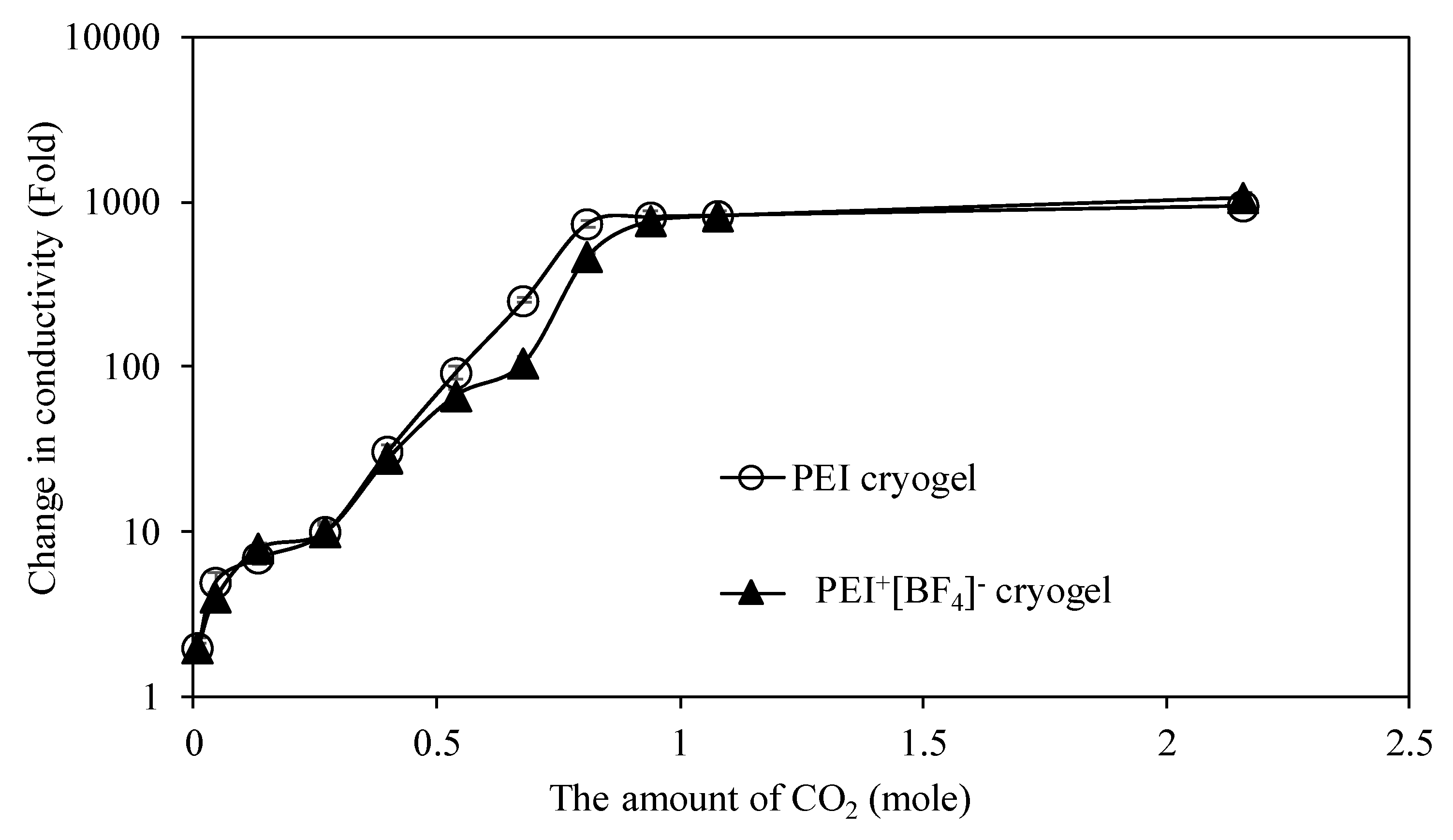
3.2.3. Sensitivity of PEI-Based Cryogels as a CO2 Gas Sensor

As the highest change in the conductivity of bare PEI and PEI+[BF4] PIL cryogels upon CO2 exposure were observed, their sensitivity against CO2 gas exposure at 200 mL/min flow rate. The sensitivity studies were done at 200 mL/min CO2 exposure for 1, 5, 15, 45, 60, 75, 90, 105, 120, and 240 min, respectively, to bare PEI and PEI+[BF4] PIL cryogels.
The amount of CO2 gas to bare PEI and PEI+[BF4] PIL cryogels was calculated as 0,009, 0.045, 0.135, 0.27, 0.40, 0.54, 0.68, 0.81, 0.94, 1.08, and 2.16 moles upon 1, 5, 15, 30, 45, 60, 75, 90, 105, 120, and 240 min exposure times, respectively. It is clearly seen from Figure 6 that the changes on conductivity of both bare PEI and PEI+[BF4] PIL cryogels start from the first min CO2 exposure with 0.009 mole of CO2 with approximately a two-fold conductivity decrease. On the other hand, it was also observed that the changes on conductivity values of bare PEI cryogels become constant with a 741-fold decrease at 0.81 mole of CO2 exposure in 90 min, whereas the conductivity values of PEI+[BF4] PIL cryogels become constant by 15 min slower than the PEI cryogel with a 762-fold decrease at 0.94 mole of CO2 exposure in 105 min. This means that the sensitivity of bare PEI and PEI+[BF4] PIL cryogels are almost the same with a change in the conductivity values for two-fold in the presence of 0.009 mole of CO2 gas. The reason for no change in conductivity or constant conductivity after 1.08 mole of CO2 exposure in 120 min was confirmed from the results in Table 2. This can also be explained by the saturation of PEI-based cryogels with CO2 leading to no more change in conductivity with further CO2 exposure anymore. Additionally, it can be seen from Figure 6 that the limit of detection of the prepared PEI, and PEI+[BF4] PIL cryogels for CO2 gas were obtained as 0.009 moles of CO2 with approximately a two-fold decrease in the conductivity of both cryogels.
According to the American Association of Heating, Refrigerating and Air Conditioning Engineers (ASHRAE) Standard 62-1989, the CO2 concentration in the environment should not exceed 1000 ppm for healthy breathing [31]. The CO2 concentration emitted in the industrial sector is much higher than this value and causes a serious increase in the greenhouse effect, which leads to a disruptive natural environment for living creatures to breathe and live healthy. The concentration of CO2 in the atmosphere was reported as 411.77 ppm in July 2019 and increased day-by-day [32]. In this study, the concentration of CO2 is 396 ± 25 ppm, and the PEI-based cryogels in the form of PIL that is used as a prospective sensor revealed a two-fold reduction in conductivity showing the potential sensor use of the prepared cryogel composite materials. Since this concentration is less than half of the value of the hazardous limit, these cryogels in the form of PIL show great potential as sensors. The potential applications of these kinds of CO2 sensors and detectors are possible in the chimney of different industrial factories, households, mining shafts, etc. that might allow us to monitor the amount of CO2 emitted/generated or released, and also be used to determine the accumulation that may occur in indoor living environments such as home, hotel, hostel, and so on. Therefore, the prepared PEI-based cryogels can be employed for these purposes.

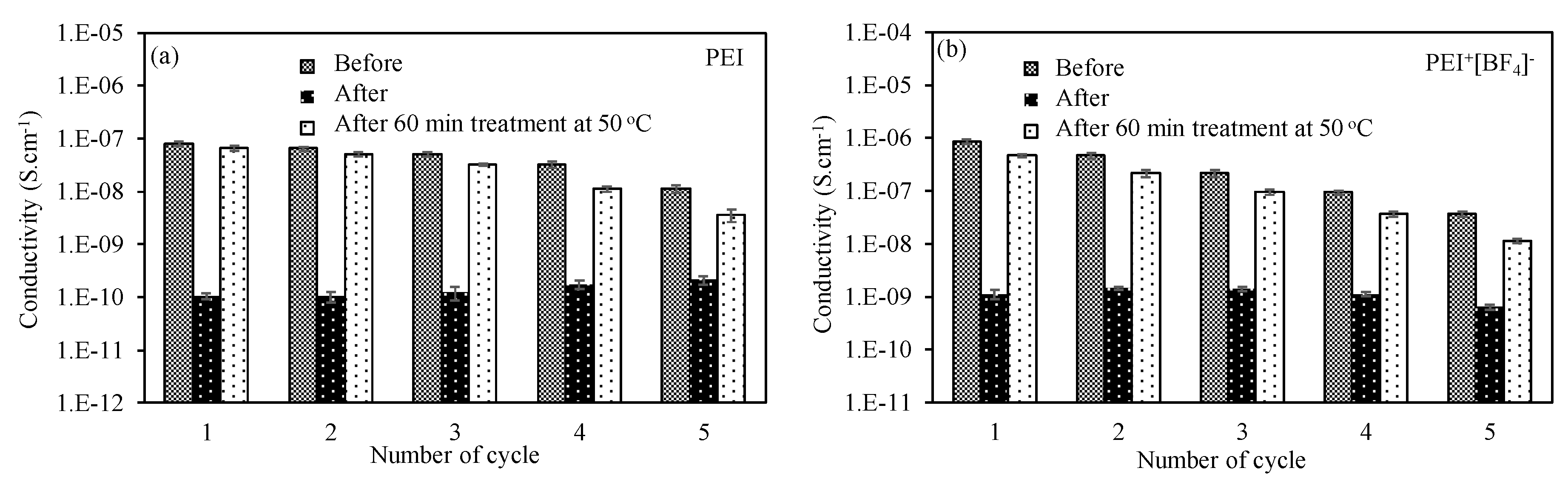
3.2.4. Reusability of PEI-Based Cryogel as a CO2 Gas Sensor

The recovery studies of bare PEI and PEI+[BF4] PIL cryogels were done by treating 240 min CO2 gas exposed bare PEI and PEI+[BF4] PIL cryogels at 50 °C for 60 min. In brief, the conductivity of bare PEI and PEI+[BF4] PIL cryogels treated with CO2 gas under a 200 mL/min flow rate for 240 min were recorded. After that, these PIL cryogels were placed into an oven at 50 °C for 60 min, and the change in conductivities were also recorded. The corresponding recovery graph of bare PEI cryogel is given in Figure 7a. It is clear that the conductivity of bare PEI cryogels decreased to 1.1 × 10⁻¹⁰ from 7.9 × 10⁻⁸ S.cm−1 with a 740-fold decrease, and then increased to 6.5 × 10⁻⁸ S.cm−1 after placing in a 50 °C oven for 60 min. These cycles were carried out for five times and the percent recovery was calculated for bare PEI cryogels as 82%, 64%, 40%, and 32%, respectively, for 2nd, 3rd, 4th, and 5th cycle, respectively. The decrease in the conductivity of bare PEI cryogels upon five cycles were decreased to approximately 630-, 410-, 180-, and 50- fold from 740-fold for 2nd, 3rd, 4th, and 5th cycles, respectively. On the other hand, the recovery studies of PEI+[BF4] PIL cryogels were also done and a corresponding graph is given in Figure 7b. The conductivity of PEI+[BF4] PIL cryogels after 240 min of CO2 exposure was decreased to 316, 151, 84, and 57-fold from 760-fold for 2nd, 3rd, 4th, and 5th cycles, respectively.
The calculated percent recovery for bare PEI+[BF4] PIL cryogels after 240 min of CO2 exposure were 47%, 43%, 38%, and 31% for 2nd, 3rd, 4th, and 5th cycles, respectively. The comparison of percent recovery values of bare PEI and PEI+[BF4] PIL cryogels revealed that percent recovery of PEI and PEI+[BF4] PIL cryogels are almost the same after up to five consecutive uses, but, during the 2nd use, bare PEI cryogels showed better recovery than PEI+[BF4] PIL cryogels. These kinds of behavior can be attributed to the existence of bigger anions in PIL for PEI that may interact with adsorbed CO2 differently than bare PEI chains.

4. Conclusions

It was demonstrated that PEI cryogels can be utilized as a template for the in-situ synthesis PANi, PPy, and PTh conductive polymers as polymer-polymer composites. It was found that the PANi containing PEI cryogels were shown higher conductivity values with 4.80 × 10⁻³ S.cm−1 than the PPy and PTh containing PEI composites cryogels. The conductivities of the IL form of PEI cryogels with various anions revealed that the conductivity values strongly dependent on the types and sizes of the anions. The conductivity of bare PEI cryogels was increased and decreased with the treatment of different IL agents. The higher conductivity was observed for Cl anions that contain PEI cryogels with 1.60 × 10⁻⁴ S.cm−1 and the lowest conductivity was observed at PEI+[N(CN)2] PIL cryogels with 1.68 × 10⁻⁹ S.cm−1. The existence of PANi within the IL form of PEI cryogels also increased the conductivity values with 30-, 8M-, 300K-, 300-, and 20-fold for PEI+Cl, PEI+[N(CN)2], PEI+[PF6], PEI+[BF4], and PEI+[SCN] PIL cryogels, respectively. The potential sensory use of PEI-based cryogels for CO2 at a 200 mL/min flow rate disclosed that the higher change in the conductivities were for PEI and PEI+[BF4] cryogels with a 1000-fold conductivity decrease after 240 min of CO2 exposure. The sensitivity and percent recovery studies were also shown almost the same results with a two-fold decrease on the conductivity of PEI and PEI+[BF4] PIL cryogels in the presence of 0.009 mole CO2 and approximately 30% recovery after the fifth usage for both bare PEI and PEI+ [BF4] PIL cryogels were accomplished. Therefore, both bare PEI and PEI+[BF4] PIL cryogels are encouraging materials that can be used as a sensor or an adsorbent for CO2. Moreover, since all components of these composites can be sensitive to different analytes, the parameters such as the size and the types of the porous polymeric networks, the types and size of the anions, the existence of other conductive polymers, and even metal ions, organic compounds, and gas molecules, as well as the environmental factors, e.g., moisture and temperature, can be taken into consideration for the design of PEI-based viable CO2 adsorbents or sensors.

Supplementary Materials

The following are available online at https://www.mdpi.com/2504-477X/4/1/27/s1. Figure S1: The schematic presentation of in situ synthesis of conductive PANi, PPy, and PTh polymers within PEI cryogels. S: FT-IR spectra of bare PEI cryogel, PEI/PANi, PEI/PPy, and PEI/PTh cryogel composites. Figure S3: Digital camera images of PEI/PANi, PEI/PPy, and PEI/PTh cryogel composites and the schematic presentation of experimental setup used in electrical conductivity measurements. Figure S4: The FT-IR spectra between 1650-1850 cm−1 wavenumber region of (a) bare PEI cryogel (b) PEI+Cl, (c) PEI+ [BF4], and (e) PEI+[SCN] PIL cryogels before and after 240 min of CO2 exposure. [200 mL/mim flow rate]. Table S1: The conductivities of bare and conductive polymer composites embedded a PEI cryogel composite and the amounts of polymers within PEI cryogels. Table S2: The effect of the anion on the electrical conductivity of bare PEI cryogels and their PANi containing IL forms of composites. Supporting Information: Synthesis of macro porous PEI and PIL PEI cryogels, In situ preparation of conductive polymers within PEI cryogels, Instruments.

Author Contributions

Conceptualization, N.S. Formal analysis, S.D. Funding acquisition, N.S. Investigation, N.S. and S.D. Methodology, N.S. and S.D. Resources, N.S. Supervision, N.S. Writing—original draft, S.D. Writing—review & editing, N.S. All authors have read and agreed to the published version of the manuscript.

Conflicts of Interest

The authors declare no conflict of interest.

References

  1. Metz, B.; Davidson, O.; de Coninck, H.; Loos, M.; Meyer, L. IPCC Special Report on Carbon Dioxide Capture And Storage, Prepared by Working Group Iii of The Intergovernmental Panel on Climate Change; Cambridge University Press: New York, NY, USA, 2005. [Google Scholar]
  2. Halmann, M.M.; Stenberg, M. Greenhouse Gas Carbon Dioxide Mitigation; CRC Press LLC: Boca Raton, FL, USA, 1999. [Google Scholar]
  3. Stewart, C.; Hessami, M.A. A study of methods of carbon dioxide capture and sequestration-the sustainability of a photosynthetic bioreactor approach. Energy Convers. Manage. 2005, 46, 403–420. [Google Scholar] [CrossRef]
  4. The Scientific Basis, Impacts, Adaptation and Vulnerability Mitigation; International Panel on Climate Change: Geneve, Switzerland, 2001.
  5. Zosel, J.; Oelssner, W.; Decker, M.; Gerlach, G.; Guth, U. The measurement of dissolved and gaseous carbon dioxide concentration. Meas. Sci. Technol. 2011, 22, 72001. [Google Scholar] [CrossRef]
  6. Perez de Vargas-Sansalvador, I.M.; Fay, C.; Phelan, T.; Fernandez-Ramos, M.D.; Capitan-Vallvey, L.F.; Diamond, D.; Benito-Lopez, F. A new light emitting diode light emitting diode portable carbon dioxide gas sensor based on an interchangeable membrane system for industrial applications. Anal. Chim. Acta 2011, 699, 216–222. [Google Scholar] [CrossRef] [PubMed] [Green Version]
  7. Herber, S.; Bomer, J.; Olthuis, W.; Bergveld, P.; van den Berg, A. A miniaturized carbon dioxide gas sensor based on sensing of pH-sensitive hydrogel swelling with a pressure sensor. Biomed. Microdevices 2005, 7, 197–204. [Google Scholar] [CrossRef]
  8. Trung, D.D.; Toan, L.D.; Hong, H.S.; Lam, T.D.; Trung, T.; Van Hieu, N. Selective detection of carbon dioxide using LaOCl-functionalized SnO2 nanowires for air-quality monitoring. Talanta 2012, 88, 152–159. [Google Scholar] [CrossRef]
  9. Dell’Amico, D.B.; Calderazzo, F.; Labella, L.; Marchetti, F.; Pampaloni, G. Converting carbon dioxide into carbamato derivatives. Chem. Rev. 2003, 103, 3857–3898. [Google Scholar] [CrossRef]
  10. Rackley, S.A. Carbon Capture and Storage; Butterworth-Heinemann: Oxford, UK, 2017. [Google Scholar]
  11. Sahiner, N.; Demirci, S. Poly ionic liquid cryogel of polyethyleneimine: Synthesis, characterization, and testing in absorption studies. J. Appl. Polym. Sci. 2016, 133, 43478. [Google Scholar] [CrossRef]
  12. Sahiner, N.; Demirci, S. The use of p(4-VP) cryogel as template for in situ preparation of p(An), p(Py), and p(Th) conductive polymer and their potential sensor applications. Synth. Metal. 2017, 227, 11–20. [Google Scholar] [CrossRef]
  13. Sahiner, N.; Demirci, S. Conducting semi-interpenetrating polymeric composites via the preparation of poly(aniline), poly(thiophene), and poly(pyrrole) polymers within superporous poly(acrylic acid) cryogels. React. Funct. Polym. 2016, 105, 60–65. [Google Scholar] [CrossRef]
  14. Vera, R.A.; Romero, H.B.; Ahumada, E. Synthesis and characterization of polyaniline and poly-ortho-methoxyaniline. Behavior against carbon steel corrosion. J. Chil. Chem. Soc. 2003, 48, n.1. [Google Scholar] [CrossRef]
  15. Xu, C.; Sun, J.; Gao, L. Synthesis of novel hierarchical graphene/polypyrrole nanosheet composites and their superior electrochemical performance. J. Mater. Chem. 2011, 21, 11253–11258. [Google Scholar] [CrossRef]
  16. Liao, J.; Wang, Y.; Chang, L.; Bao, W. A process for de sulfurization of coking benzene by a two-step method with reuse of sorbent/thiophene and its key procedures. Green Chem. 2015, 17, 3164–3175. [Google Scholar] [CrossRef]
  17. Fatoni, A.; Numnuam, A.; Kanatharana, P.; Limbut, W.; Thavarungkul, P. A novel molecularly imprinted chitosan-acrylamide, graphene, ferrocene composite cryogel biosensor used to detect microalbumin. Analyst 2014, 139, 6160–6167. [Google Scholar] [CrossRef]
  18. Kangkamano, T.; Mumnuam, A.; Limbut, W.; Kanatharana, P.; Thavarungkul, P. Chitosan cryogel with embedded gold nanoparticles decorated multıwalled carbon nanotubes modified electrode for highly sensitive flow based non-enzymatic glucose sensor. Sens. Actuat. B Chem. 2017, 246, 85–863. [Google Scholar] [CrossRef]
  19. Choi, W.; Min, K.; Kim, C.; Koo, Y.S.; Jeon, J.W.; Seo, H.; Park, Y.K.; Choi, M. Epozide-functionalization of polyethyleneimne for synthesis of stable carbon dioxide adsorbent in temperature swing adsorption. Nat. Commun. 2016, 7, 12640. [Google Scholar] [CrossRef] [Green Version]
  20. Lee, M.S.; Lee, S.Y.; Park, S.J. Preparation and characterization of multiwalled carbon nanotubes imprenated with polyethyleneimine for carbondioxide capture. Int. J. Hydrogen Energy 2015, 40, 3415–3421. [Google Scholar] [CrossRef]
  21. Wang, W.; Zeng, Q.; Li, M.; Zheng, W.; Christianson, D.; Economy, J. Adsorptive removal of carbon dioxide using polyethyleneimne loaded glass fiber in a fixed bed. Colloid. Surf. A Physicochem. Eng. Aspect. 2015, 481, 117–124. [Google Scholar] [CrossRef] [Green Version]
  22. Star, A.; Han, T.R.; Joshi, V.; Gabriel, J.C.P.; Grüner, G. Nanoelectronic carbon dioxide sensors. Adv. Mater. 2004, 16, 22. [Google Scholar] [CrossRef]
  23. Srinives, S.; Sarkar, T.; Hernandez, R.; Mulchandani, A. Aminiature chemiresistor sensor for carbon dioxide. Anal. Chim. Acta 2015, 874, 54–58. [Google Scholar] [CrossRef]
  24. Selampinar, F.; Toppare, L.; Akbulut, U.; Yalcin, T.; Suzer, S. A conducting composite of polypyrrole II. As a gas sensor. Synth. Metal. 1995, 68, 109–116. [Google Scholar] [CrossRef]
  25. Willa, C.; Yuan, J.; Niedeberger, M.; Koziej, D. When nanoparticles meet poly(ionic liquid)s: Chemoreistive CO2 sensing at room temperature. Adv. Funct. Mater. 2015, 25, 2537–2542. [Google Scholar] [CrossRef] [Green Version]
  26. Behera, K.; Pandey, S.; Kadyan, A.; Pandey, S. Ionic liquid-based optical and electrochemical carbon dioxide sensors. Sensors 2015, 15, 30487–30503. [Google Scholar] [CrossRef] [Green Version]
  27. Brennecke, J.F.; Gurkan, B.E. Ionic liquids for CO2 capture and emission reduction. J. Phys. Chem. Lett. 2010, 1, 3459–3464. [Google Scholar] [CrossRef]
  28. Lu, B.; Wang, X.; Xia, Y.; Liu, N.; Li, S.; Li, W. Kinetics of carbon dioxide absorption into mixed aqueous solutions of MEA+ [Bmim]BF4 using a double stirred cell. Energy Fuels 2013, 27, 6002–6009. [Google Scholar] [CrossRef]
  29. Dutcher, B.; Fan, M.; Russell, A.G. Amine-based CO2 capture technology development from the beginning of 2013-A review. ACS Appl. Mater. Interfaces 2015, 7, 2137–2148. [Google Scholar] [CrossRef]
  30. Carvalho, P.J.; Alvarez, V.H.; Marrucho, I.M.; Aznar, M.; Couthinho, J.A.P. High pressure phase behavior or carbon dioxide in 1-buthyl-3-methylimidazolium bis(trifluoromethylsulfonyl)imide and 1-butyl-3-methylimidazolium dicyanamide ionic liquids. J. Supercrit. Flu. 2009, 50, 105–111. [Google Scholar] [CrossRef]
  31. Erdmann, C.A.; Apte, M.G. Mucous membrane and lower respiratory building related symptoms in relation to indoor carbon dioxide concentrations in the 100-building BASE dataset. Indoor Air 2004, 14, 127–134. [Google Scholar] [CrossRef]
  32. Lin, Y.; Fan, Z. Compositing strategies to enhance the performance of chemiresistive CO2 gas sensors. Mater. Sci. Semicond. Process 2020, 107, 104820. [Google Scholar] [CrossRef]
Figure 1. SEM images of prepared (a) bare Polyethyleneimine (PEI) cryogel, (b) PEI/PANi, (c) PEI/PPy, and (d) PEI/PTh cryogel composites.
Jcs 04 00027 g001
Figure 2. (a) Comparison of the measured conductivities of bare PEI cryogel, PEI/PANi, PEI/PPy, and PEI/PTh cryogel composites, and (b) PANi containing PEI PIL cryogels composites.
Jcs 04 00027 g002
Figure 3. The schema of the presentation of CO2 gas exposure on PEI-based cryogels and composites.
Jcs 04 00027 g003
Figure 4. The change in conductivities of (a) bare PEI cryogel, (b) PEI/PANi, (c) PEI/PPy, and (d) PEI/PTh cryogel composites under CO2 gas exposure. [200 mL/min flow rate].
Jcs 04 00027 g004
Figure 5. The changing on conductivities of (a) PEI+Cl, (b) PEI+[N(CN)2] (c) PEI+ [PF6], (d) PEI+ [BF4], and (e) PEI+ [SCN] PIL cryogels under CO2 gas exposure. [200 mL/min flow rate].
Jcs 04 00027 g005
Figure 6. The comparison of sensitivities of bare PEI cryogel and PEI+[BF4] cryogel under different amounts of CO2 exposure [200 mL/min flow rate].
Jcs 04 00027 g006
Figure 7. The percent recovery studies of (a) bare PEI cryogel and (b) PEI+ [BF4] cryogel under 240 min CO2 gas exposure [200 mL/min flow rate].
Jcs 04 00027 g007
Table 1. The conductivities of bare PEI and PEI conductive polymer composites before and after CO2 gas exposure at various times.
Cryogel CompositeConductivity (S.cm−1)
30 min60 min120 min240 min
PEIBefore7.0 × 10−87.1 × 10−88.3 × 1089.2 × 108
After6.9 × 10−97.6 × 10−101.0 × 10−109.7 × 10⁻¹¹
PEI/PANiBefore4.5 × 10−34.3 × 10−34.6 × 10−34.9 × 10⁻³
After1.1 × 10−21.1 × 10−22.3 × 10−28.5 × 10⁻³
PEI/PPyBefore1.3 × 10−41.3 × 10−41.2 × 10−41.4 × 10⁴
After7.5 × 10−56.5 × 10−59.2 × 10−51.4 × 10⁻⁴
PEI/PThBefore2.1 × 10−62.0 × 10−61.8 × 10−62.2 × 10⁻⁶
After1.7 × 10−75.7 × 10−95.9 × 10−96.5 × 10⁻⁹
Table 2. The change in conductivities of bare polyethyleneimine (PEI) and IL forms of PANi containing composites after CO2 gas exposure at various times.
The Decrease in Conductivity (Fold)
PEIPEI+
Cl
PEI+
[N(CN)2]
PEI+
[PF6]
PEI+
[BF4]
PEI+
[SCN]
0000000
30104.4151013.3
601002011066.730
12010002501101000160
24010003001101000300

