Thermal Ageing of a Hybrid Composite Rod for Next Generation Overhead Power Lines


Abstract
1. Introduction
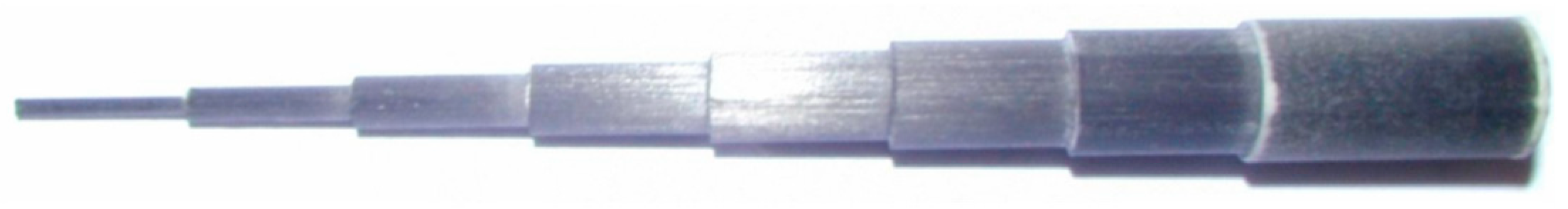
2. Materials and Methods
3. Experimental Results
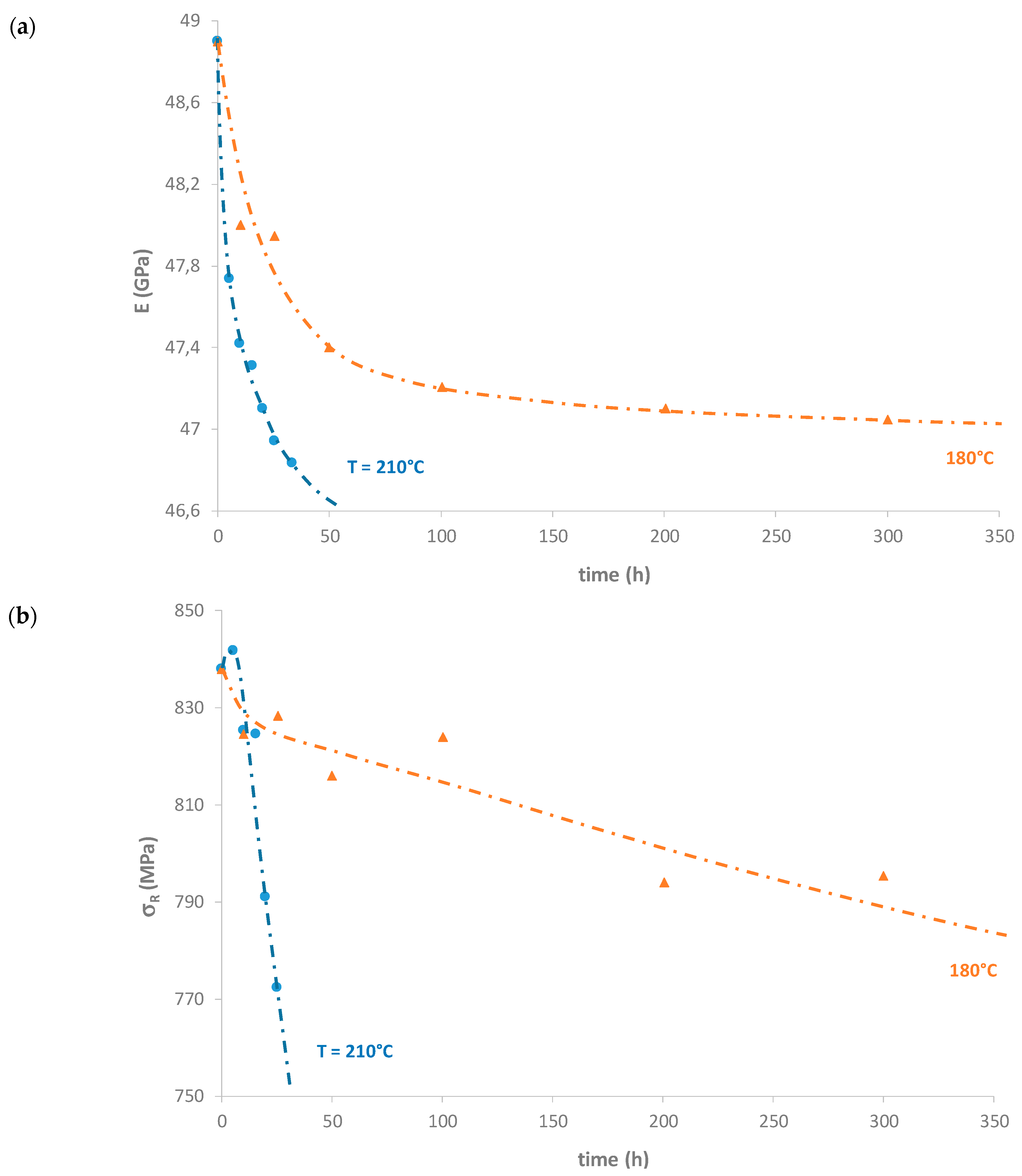
3.1. Mechanical Characterization
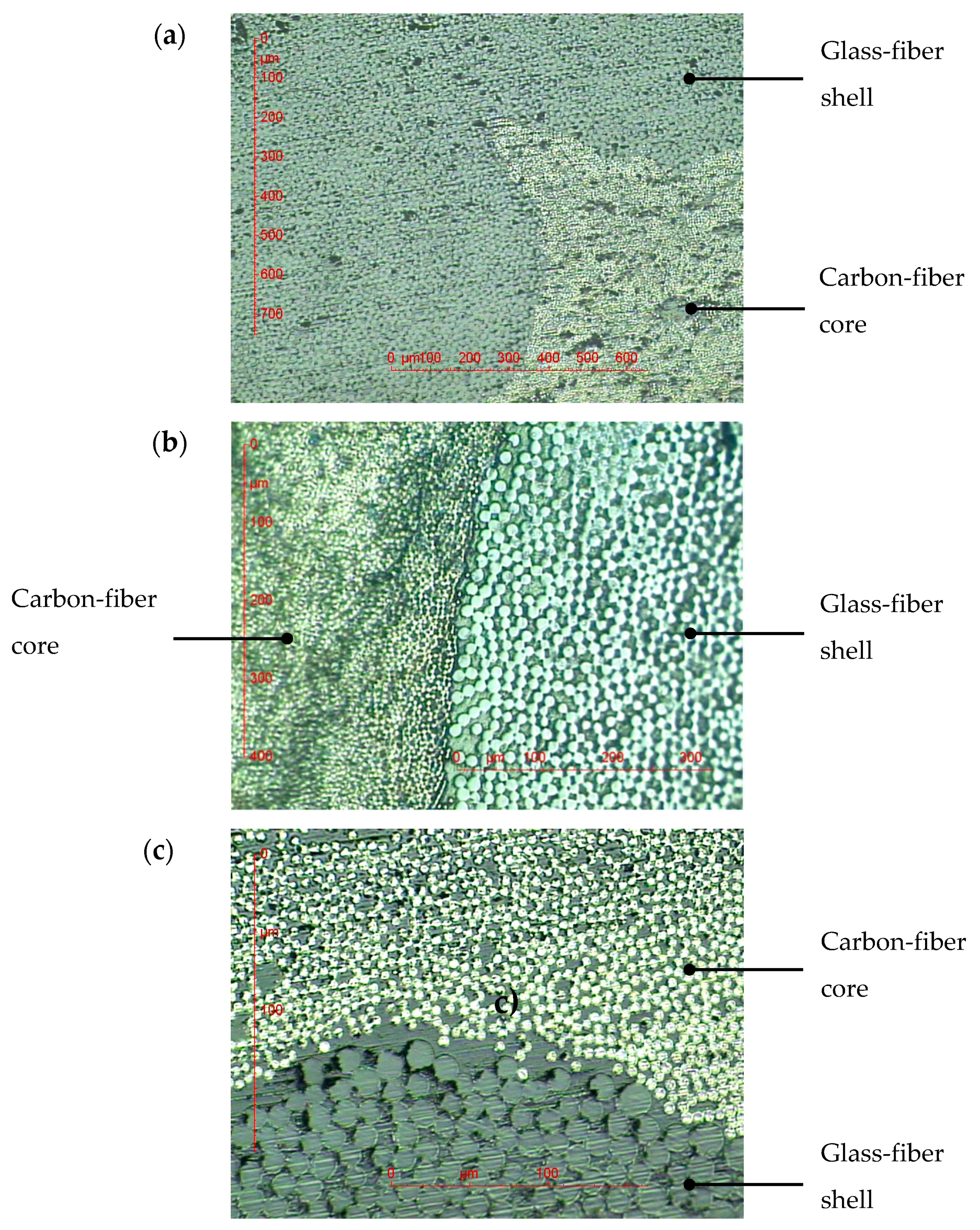
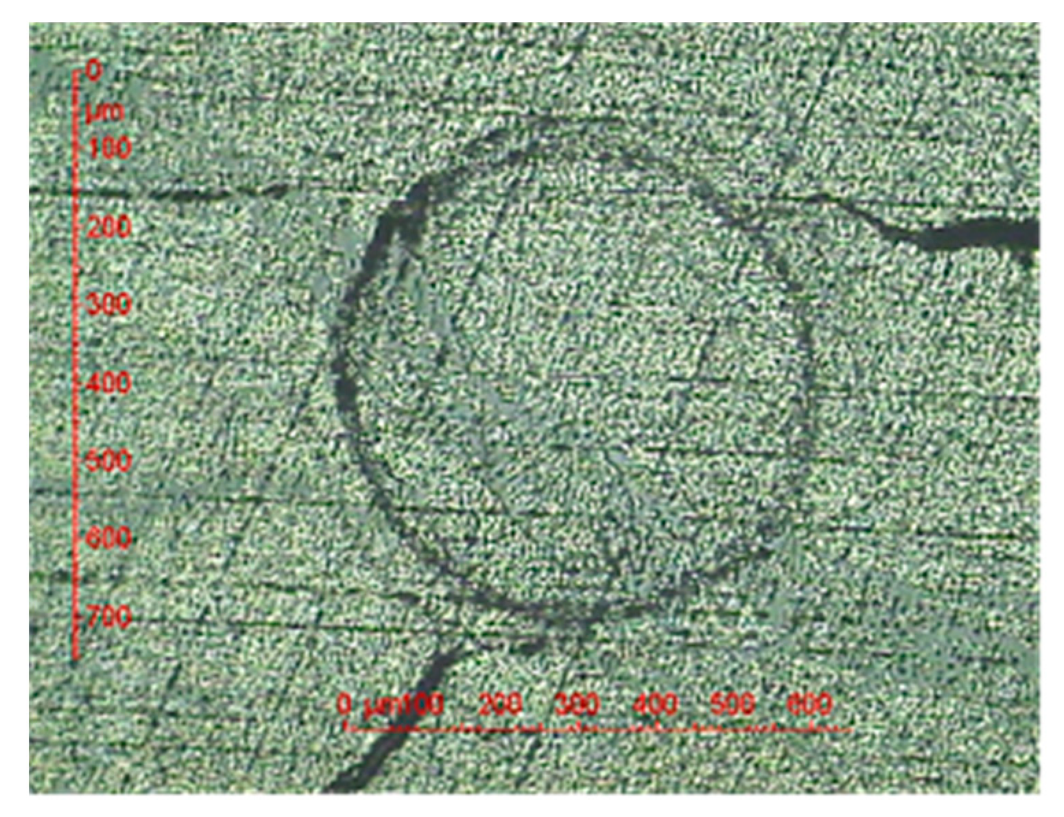
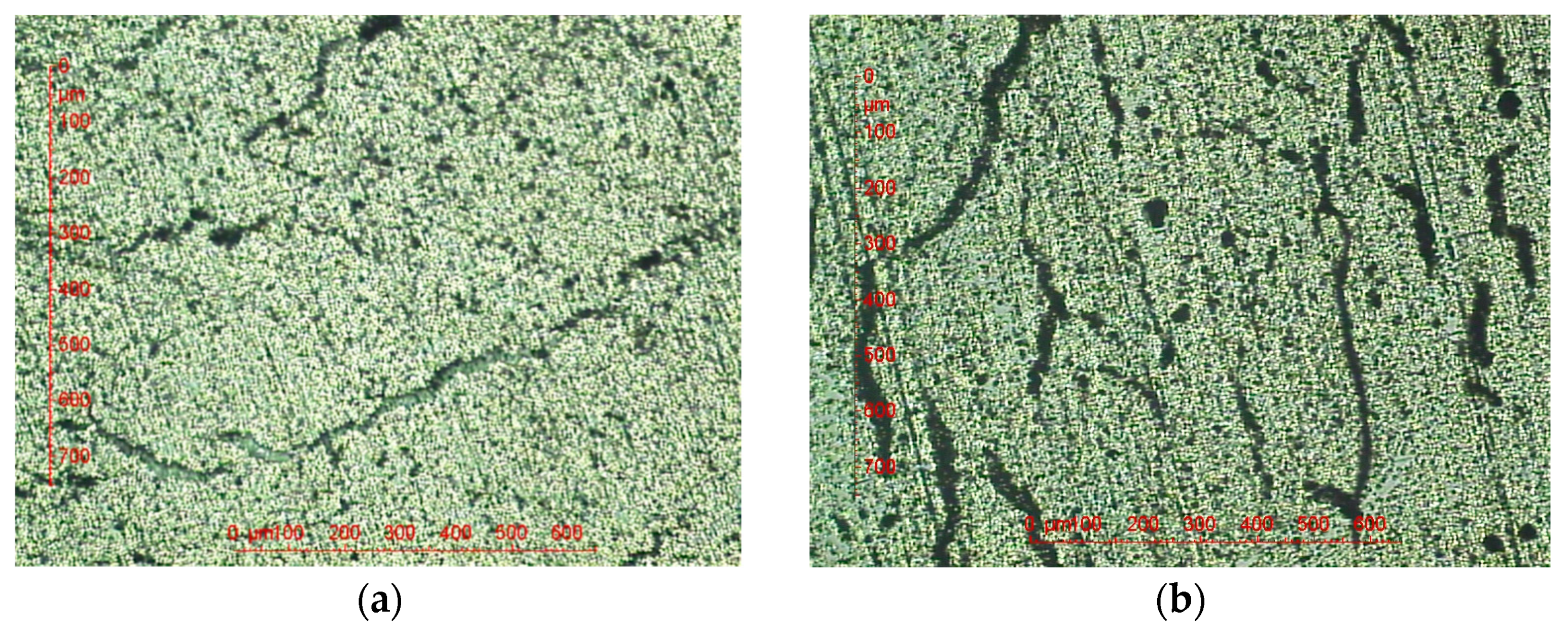
3.2. Optical Microscopic Examinations
3.3. Physicochemical Characterizations
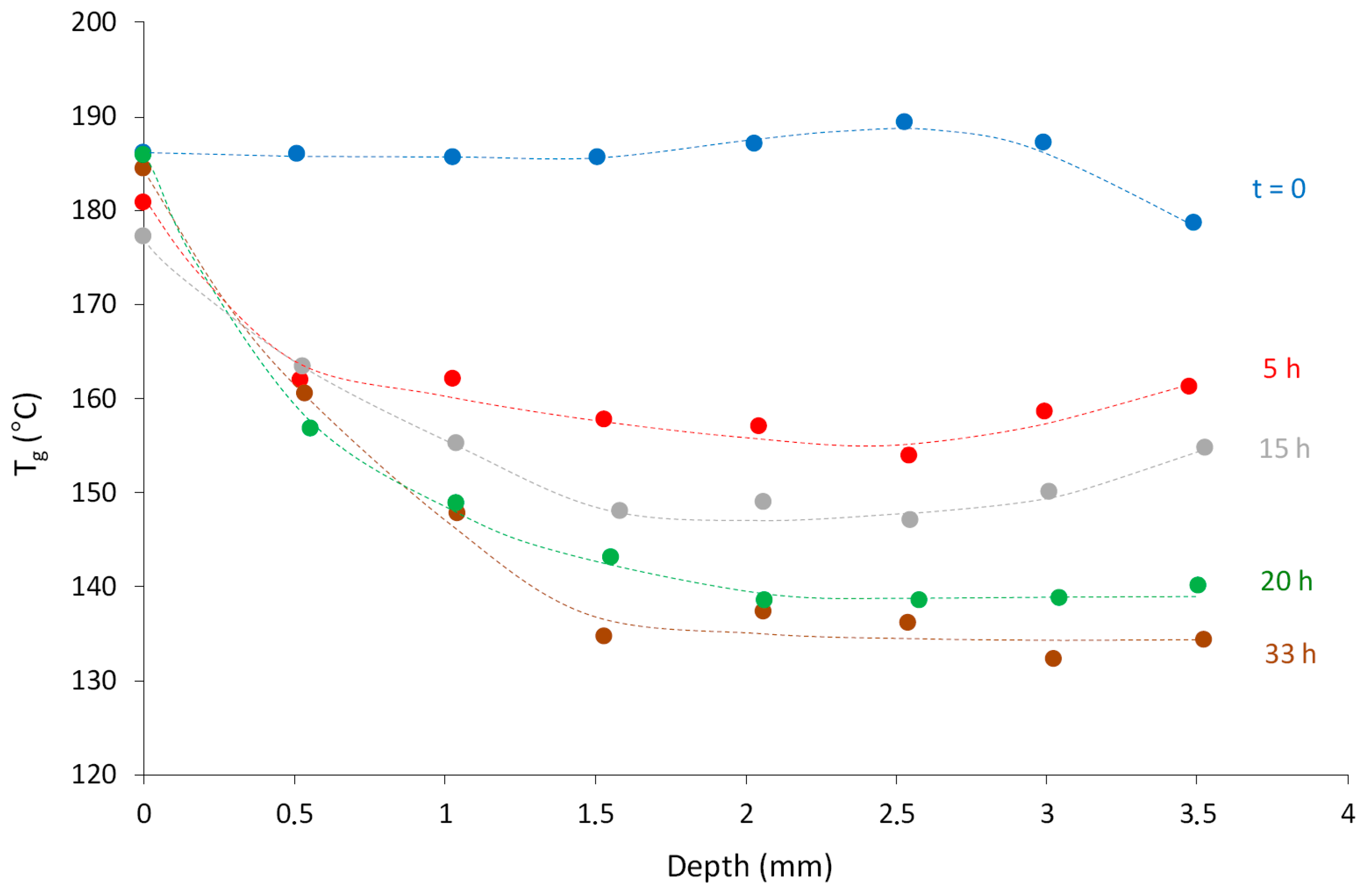
- Between 180 and 210 °C, the thermolysis of the epoxy-anhydride matrix is far from being negligible. It consists of an efficient chain scission process leading to the destruction of elastically active chains and crosslink nodes and, thus, to a catastrophic decrease in Tg in the carbon-fiber core. The rate of Tg decrease is maximum from the early periods of exposure and, then, slows down gradually so that Tg reaches an asymptotic value in the long term. The asymptotic values measured by DSC for the different ageing temperatures under study in the carbon-fiber core are reported in Table 4. All these values were confirmed by viscoelasticimetry.
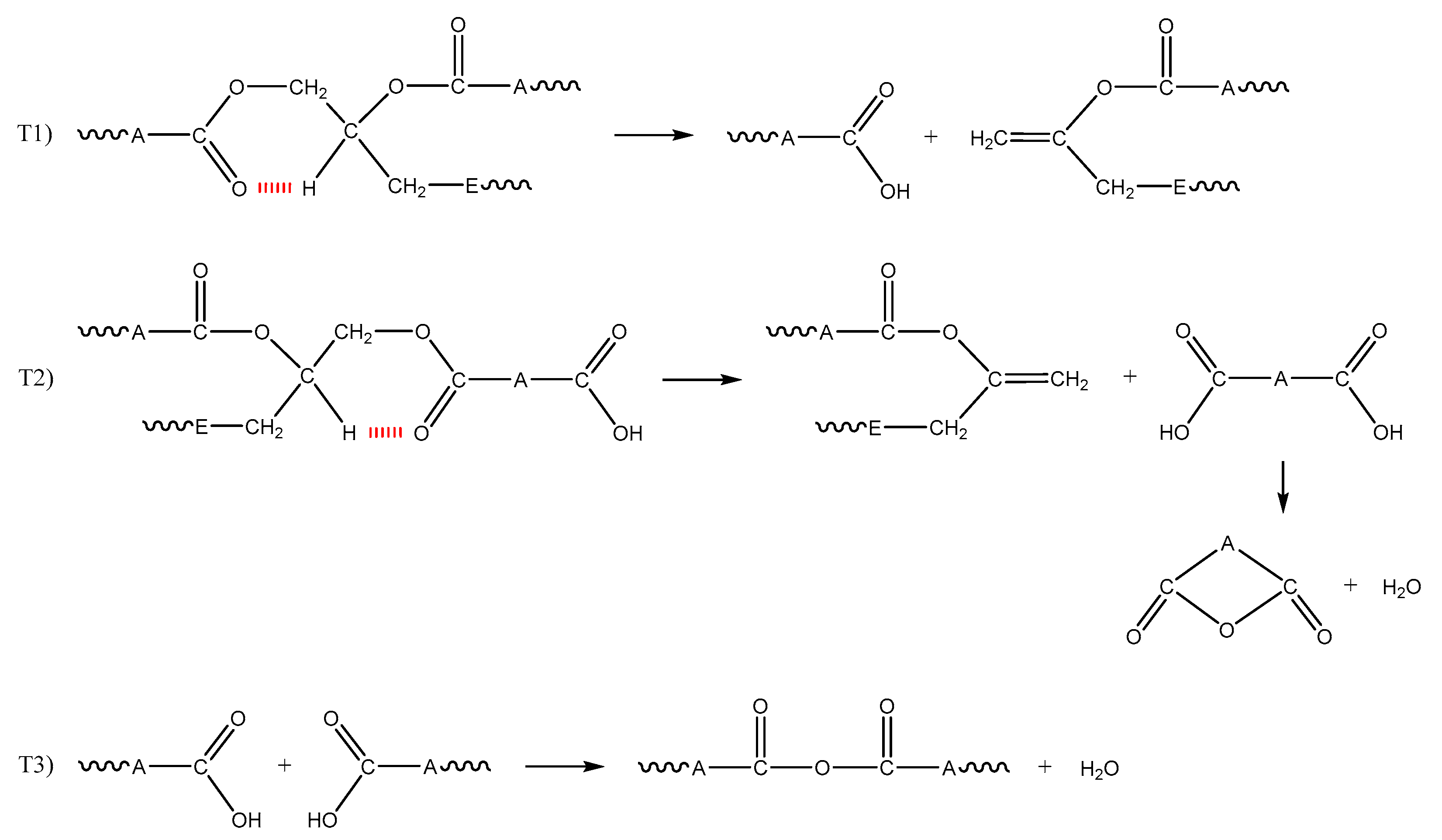
- Thermolysis presumably consists of the thermal rearrangement of ester groups, a well-known reaction for linear polyesters [14,15,16]. Indeed, this reaction would lead to the formation of terminal carboxylic acids and double bonds. Then, the resulting carboxylic acids could condensate into anhydrides. All these chemical events are summarized in the mechanistic Scheme 1. They can explain the formation of a large part of the degradation products detected by FTIR spectrometry. It should be emphasized that the second chemical event (denoted T2 in Scheme 1) is assumed to generate volatile compounds such as cyclic anhydrides and water. It is in competition with the condensation of carboxylic acid chain ends, leading to the formation of new covalent bridges in the macromolecular network (see event T3 in Scheme 1).
- In addition, between 180 and 210 °C, the epoxy-anhydride matrix is very sensitive to oxidation because its chemical structure contains, as main reactive sites, very labile hydrogens located in the α position of a heteroatom (oxygen). Indeed, the corresponding C–H bonds are characterized by a much lower dissociation energy (ED ≈ 376 kJ·mol−1) than in polyethylene (ED ≈ 393 kJ·mol−1) [13,17,18]. Korcek et al. tried to correlate the rate constant k3 for the propagation of oxidation to the chemical structure of a series of hydrocarbon substrates. They found that Log(k3) is a linear decreasing function of ED of the weakest C–H bond [19].
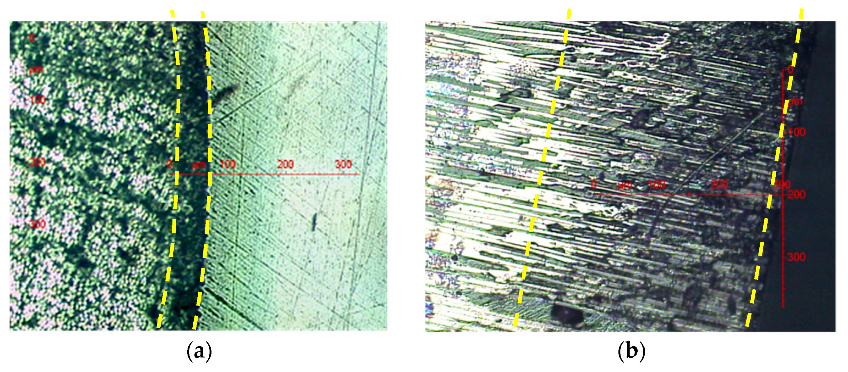
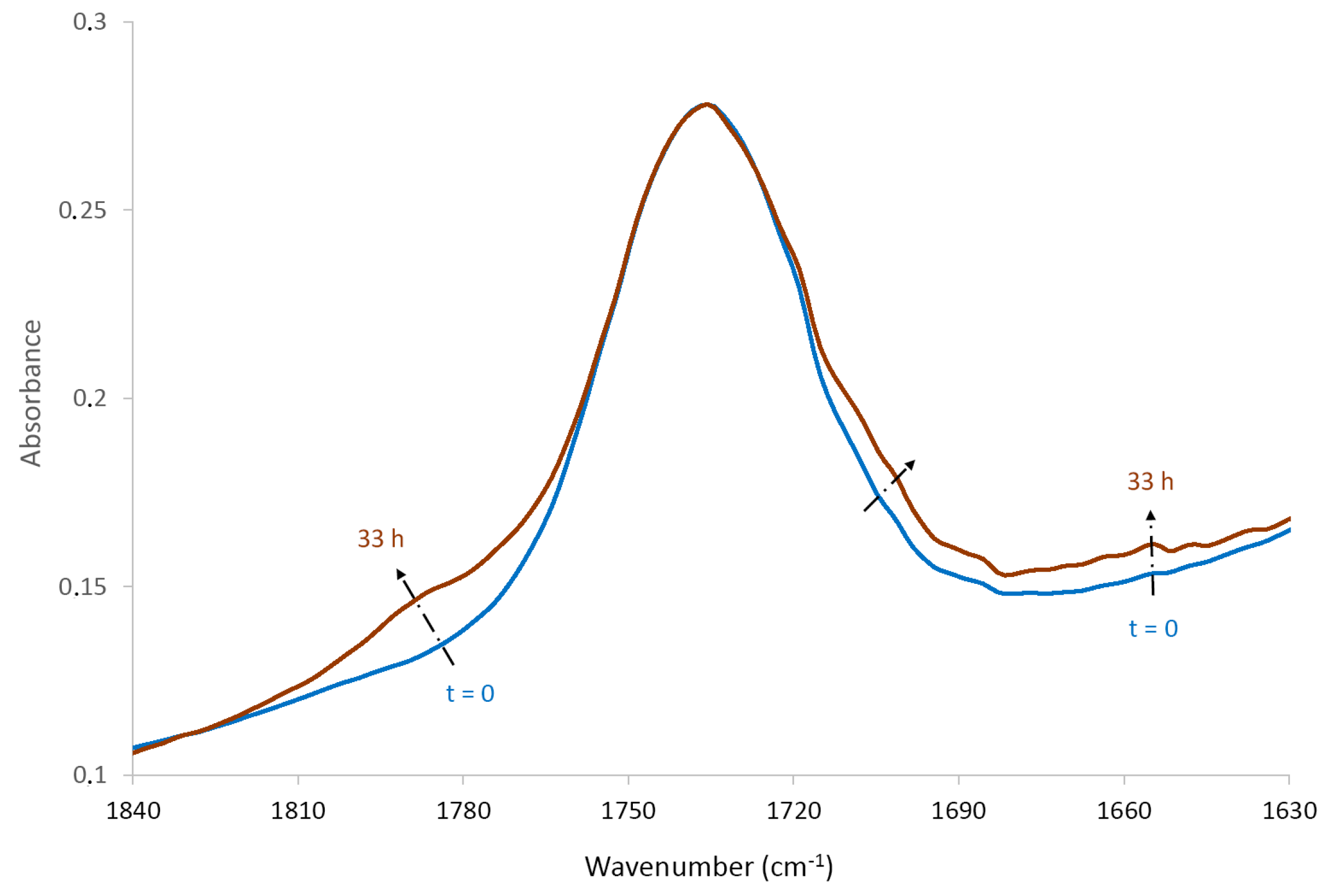
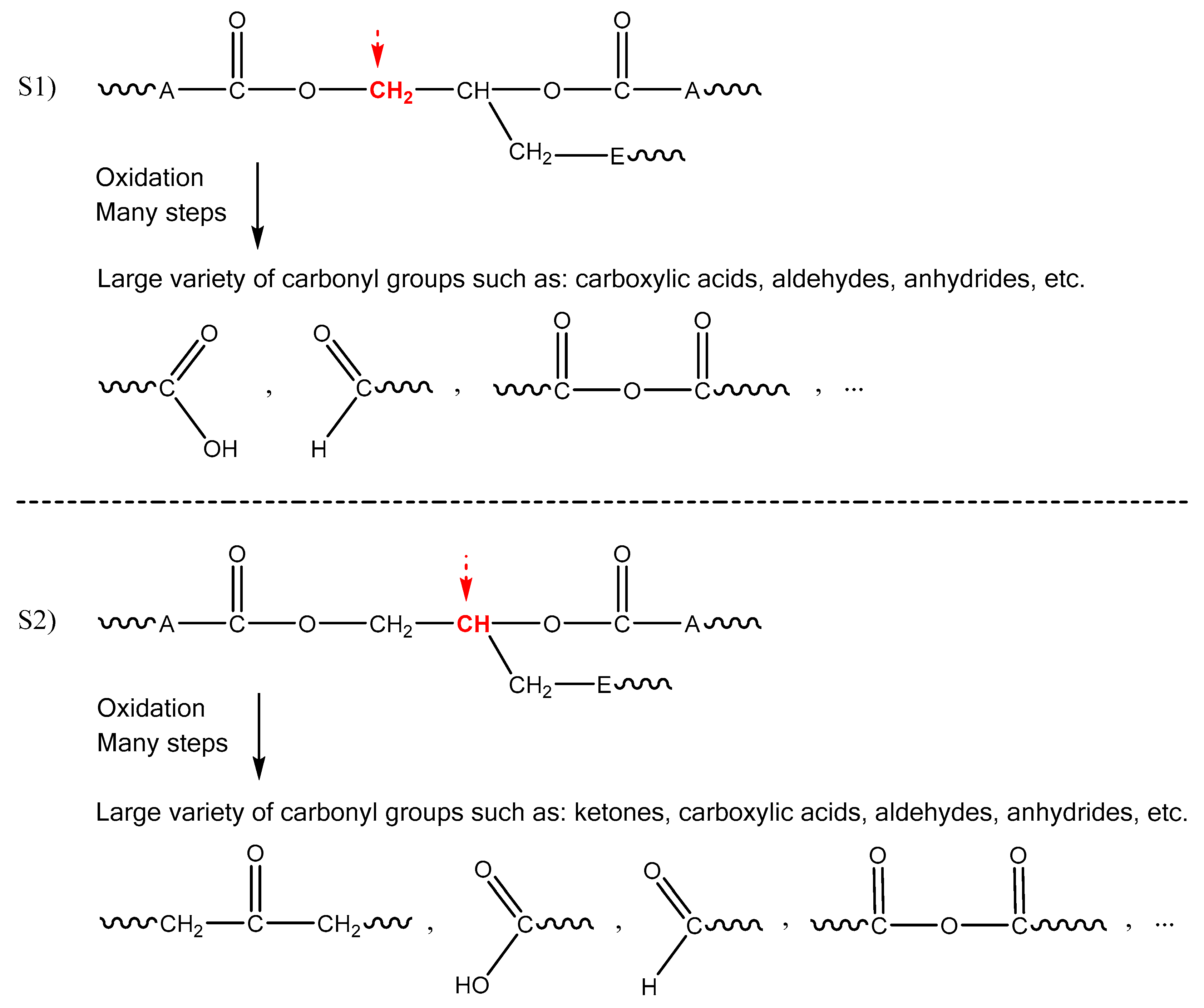
- Since the oxidation kinetics is diffusion controlled, it leads to the formation of a superficial oxidized layer of which the maximal thickness in the radial direction is about 60 µm (see Table 3). In Figure 11, it can be clearly seen that oxidation inhibits almost totally thermolysis on the outer surface of the glass-fiber shell. This result is not surprising because the C–H bond involved in the thermolysis reaction (see Scheme 1) is also one of the two preferential oxidation sites in epoxy-anhydride matrices (denoted S2 in Scheme 2). It can be thus concluded that the radical attack on site S2 prevents the thermal rearrangement of the ester group, i.e., the thermolytic chain scission process.
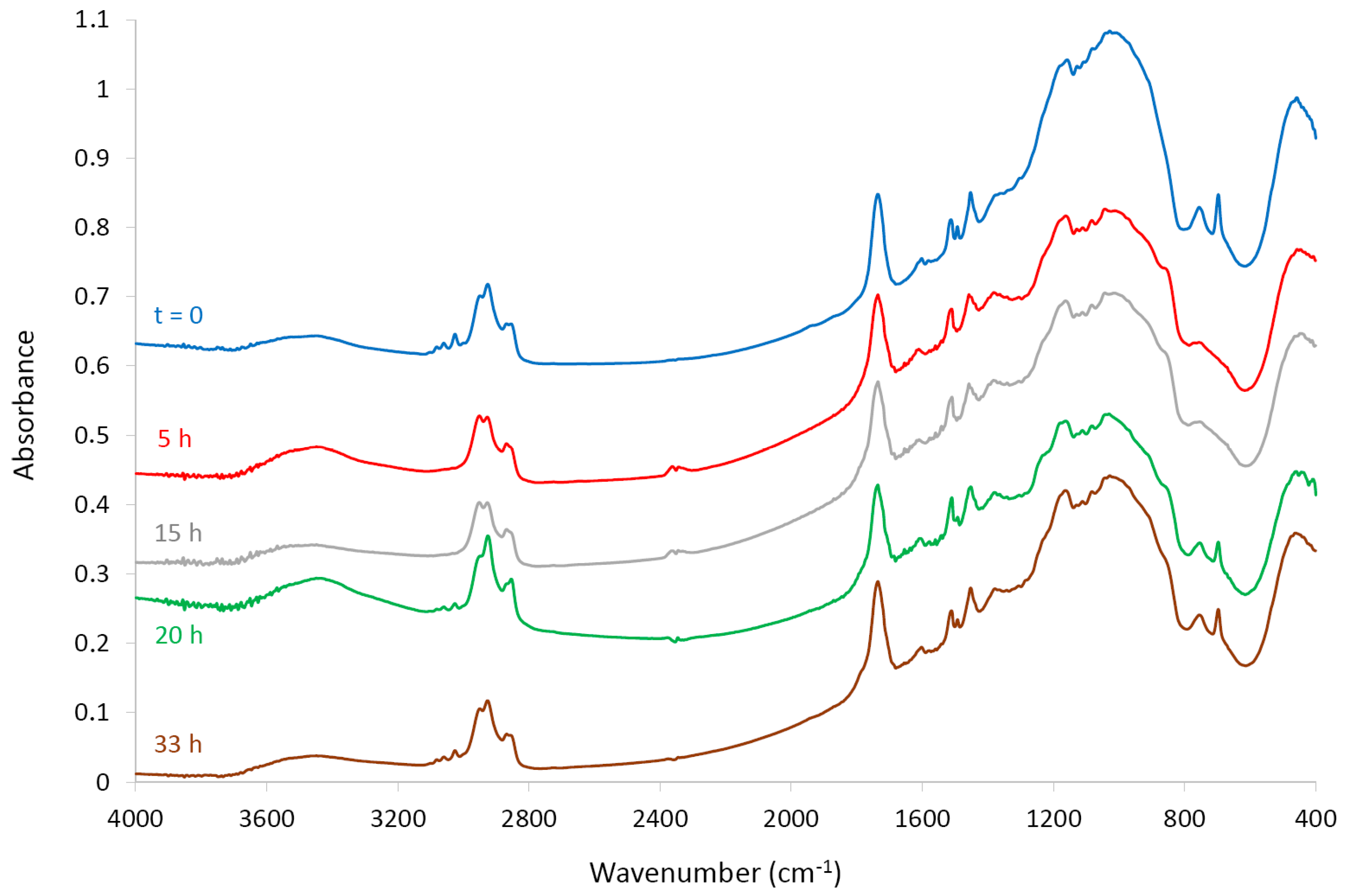
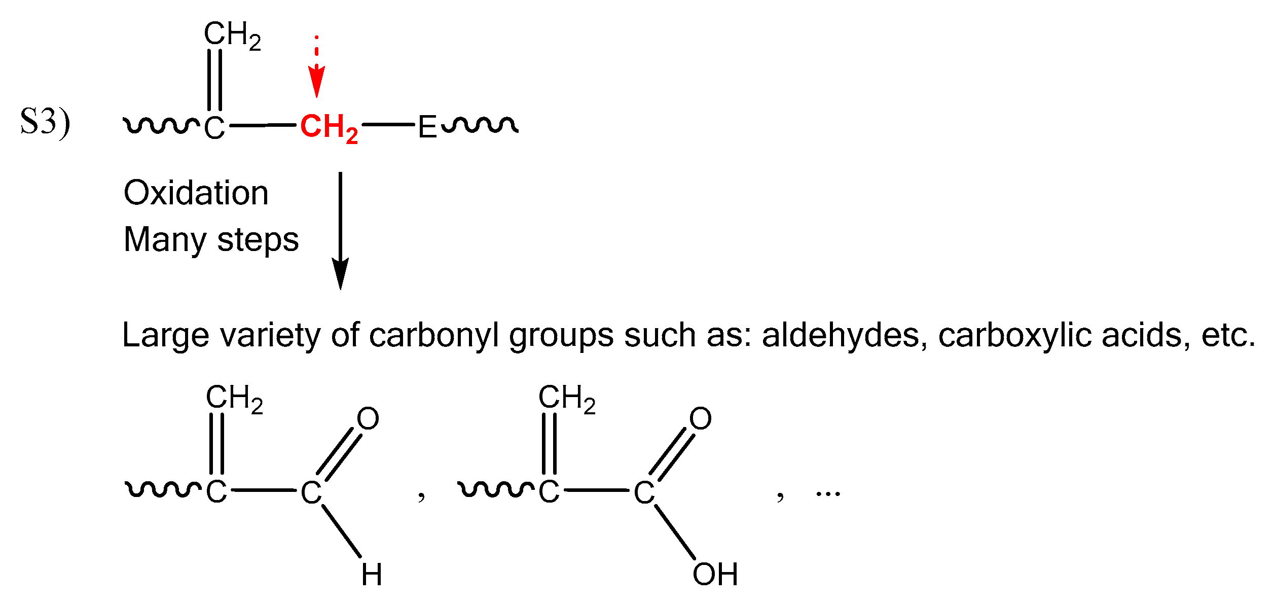
- As shown in Figure 10, thermal oxidation leads to the formation of a large variety of new types of saturated and unsaturated carbonyl groups such as ketones, carboxylic acids, aldehydes, anhydrides, etc. The formation of saturated carbonyls can be easily explained by the radical attack on sites S1 and S2 (see Scheme 2). In contrast, the formation of unsaturated carbonyls is presumably due to the radical attack on a second population of sites (denoted S3 in Scheme 3): allylic hydrogens. Indeed, let us remember that allylic hydrogens are also very labile, certainly much more labile than hydrogens located in the α position of a heteroatom, given that the corresponding C–H bond is characterized by an even lower dissociation energy of only ED ≈ 335 kJ·mol−1 [20]. Thereafter, it will be considered that oxidation propagates almost instantaneously on site S3.
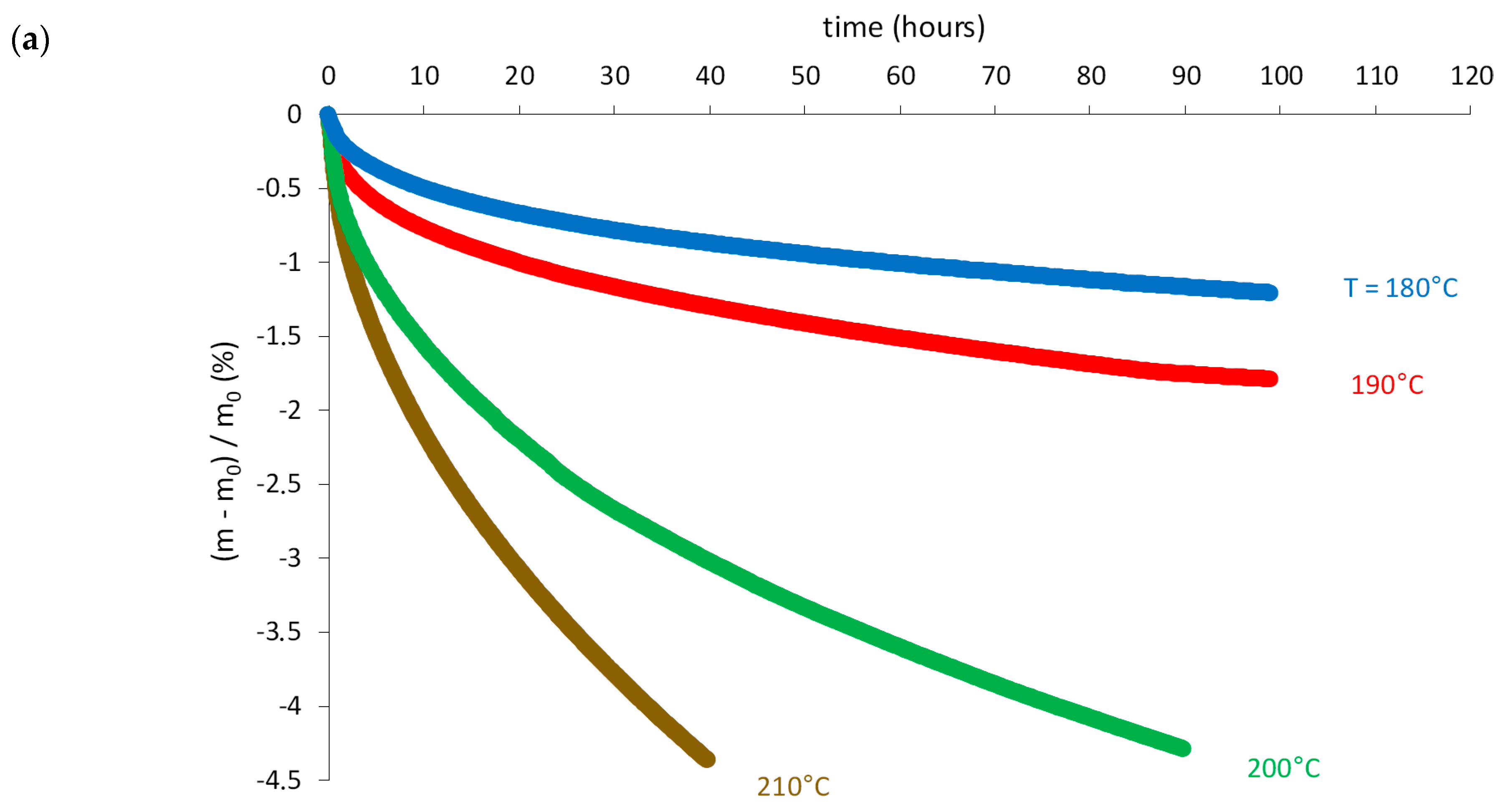
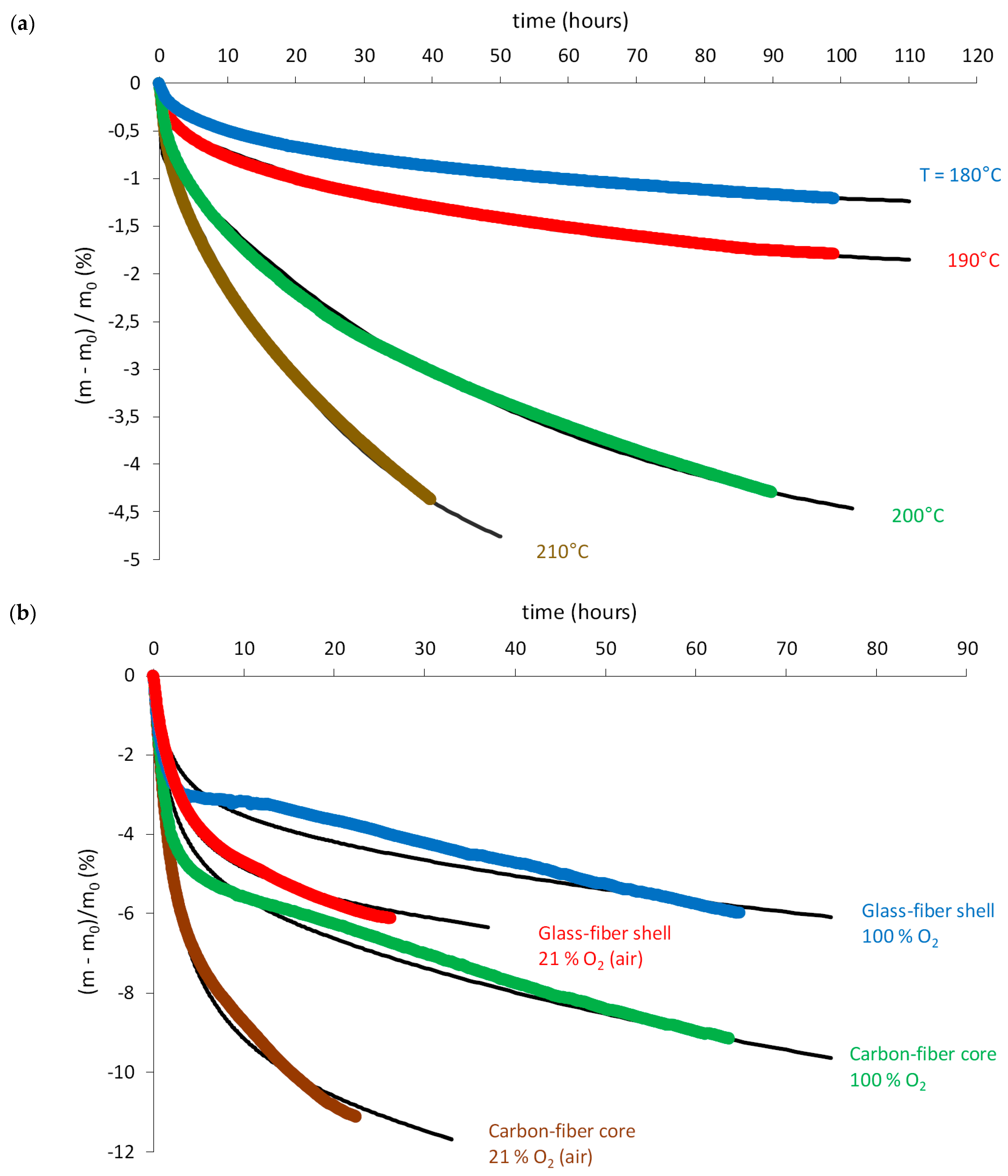
- As expected, thermolysis leads to nonnegligible mass losses. As an example, the carbon-fiber core loses about −1% after a hundred hours in nitrogen at 180 °C and more than 4% after only a few dozen hours in nitrogen at 200 and 210 °C (Figure 12a). Thus, thermolysis is clearly thermo-activated.
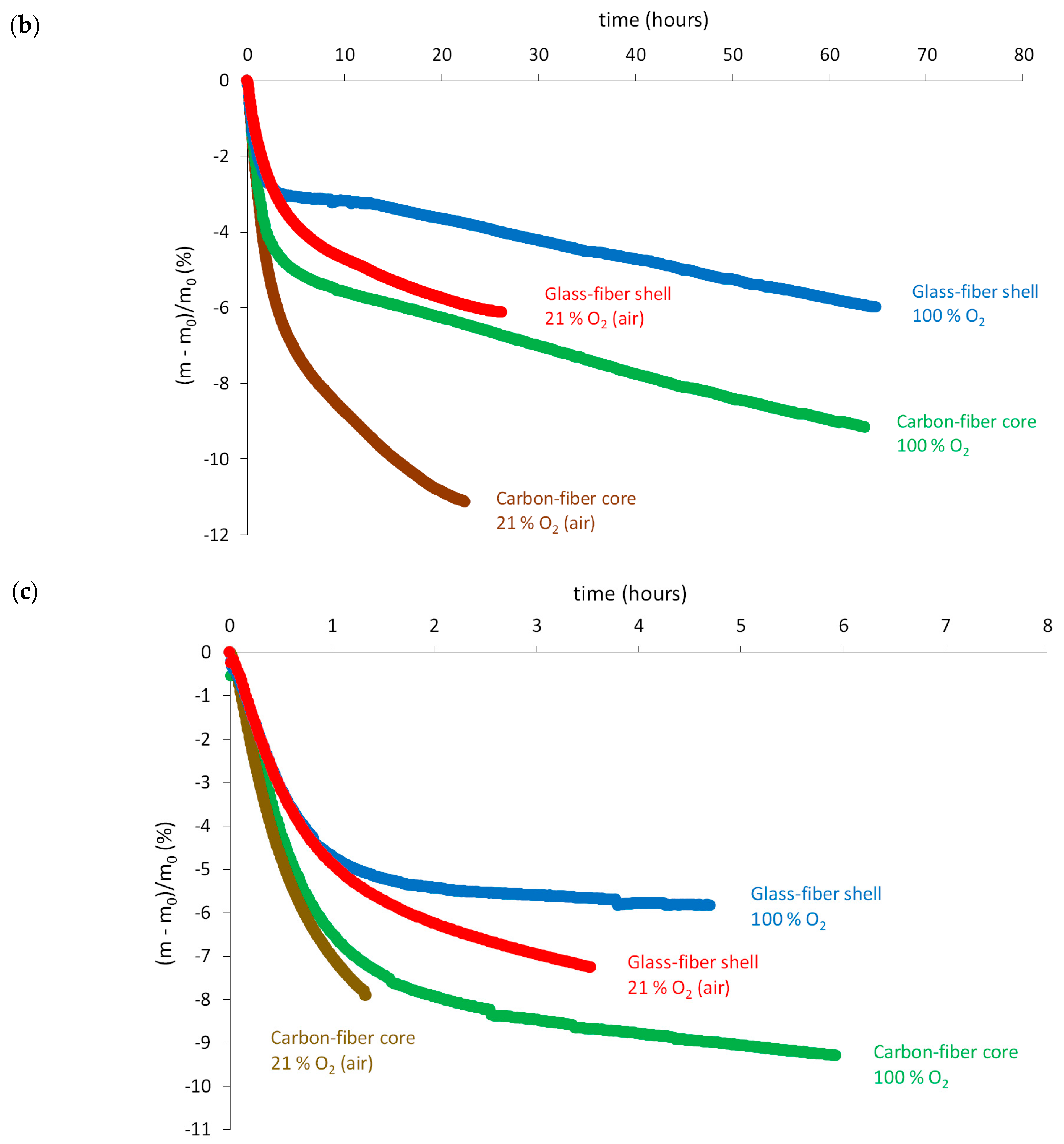
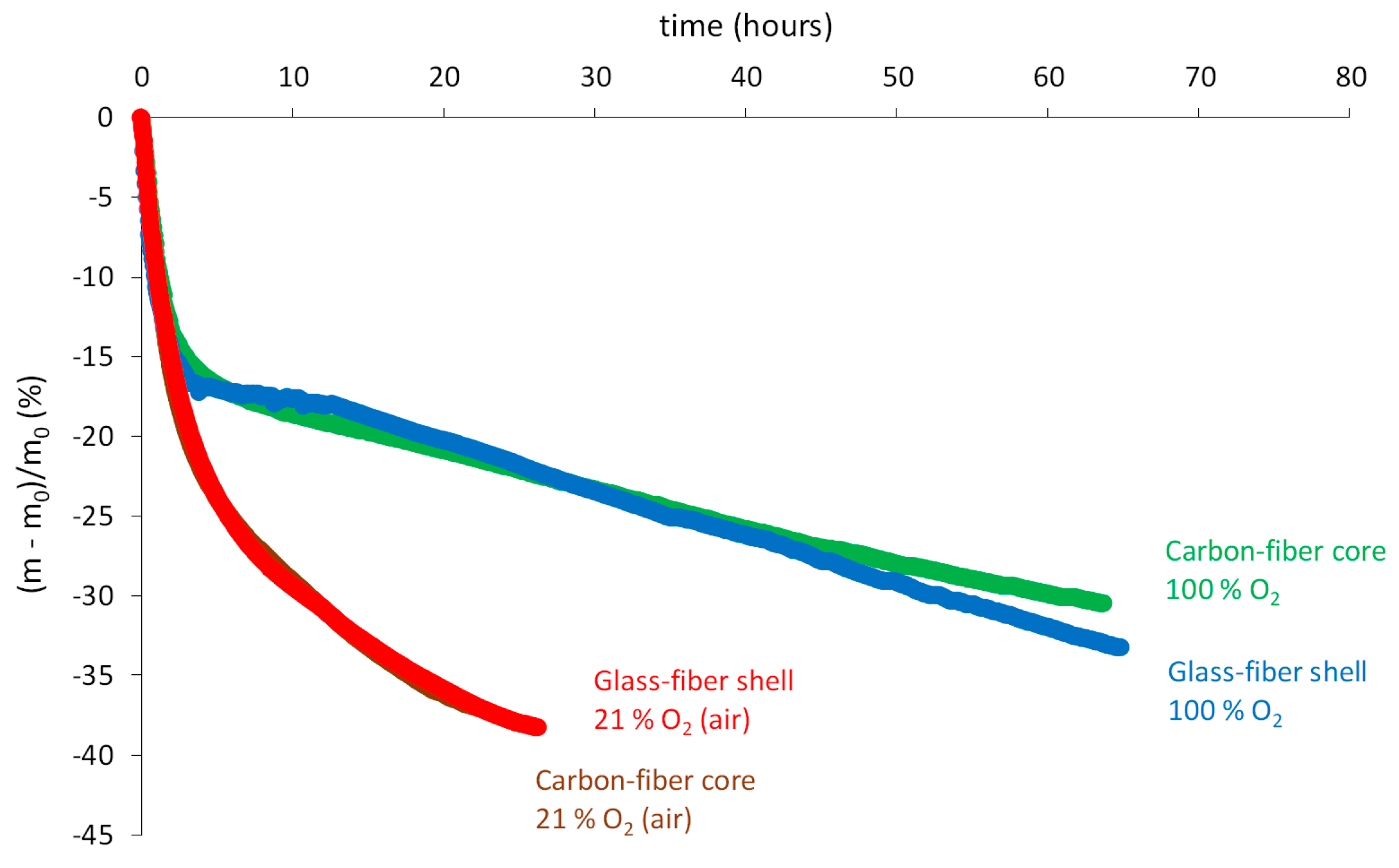
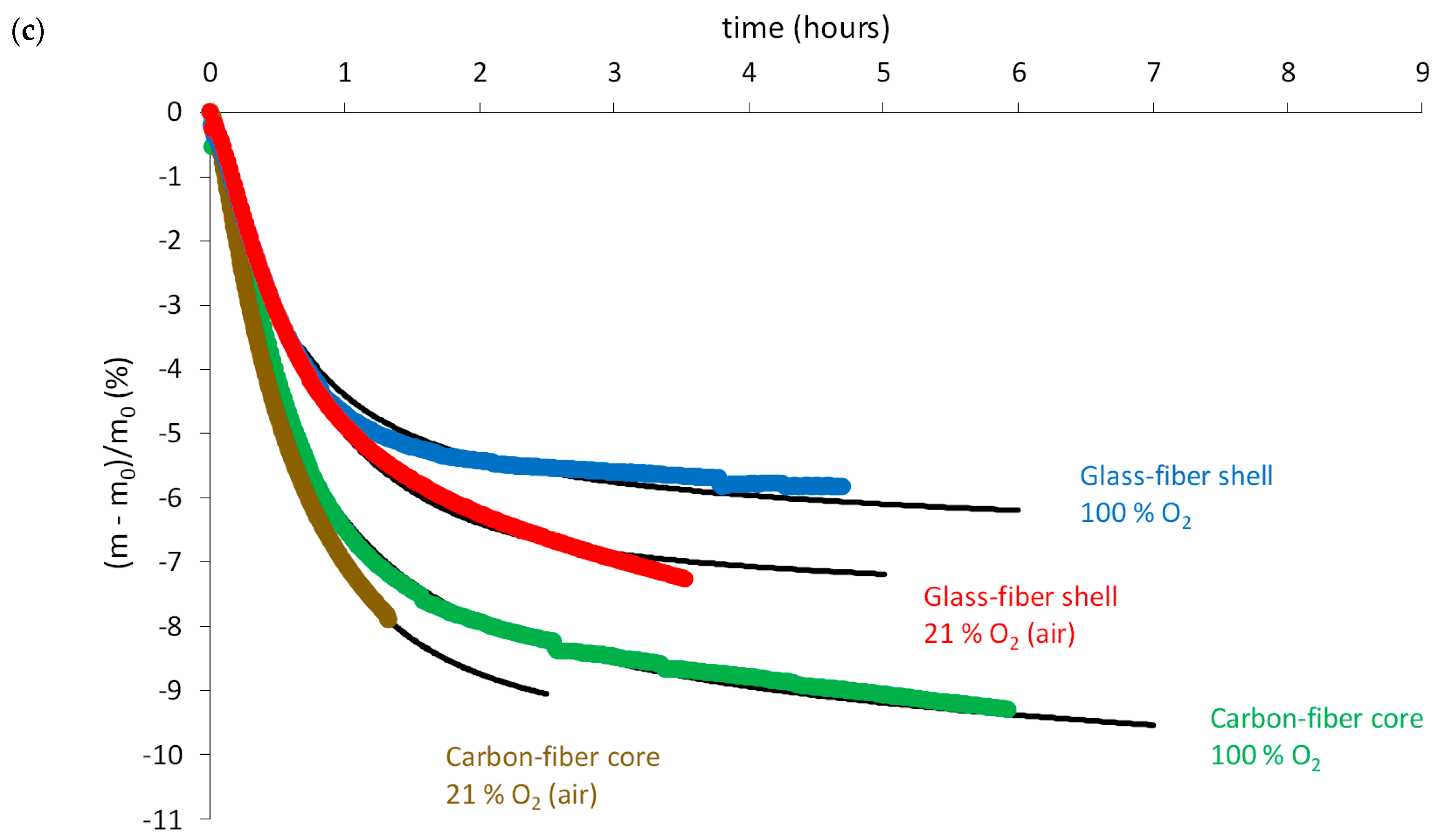
- Thermal oxidation leads to stronger mass losses than thermolysis presumably because it produces a large amount of small molecules (mainly water and carbon dioxide), which can thus easily leave the epoxy-anhydride matrix. As an example, the carbon-fiber core loses more than 10% after only 15 h in air at 180 °C and after only a few hours in air at 210 °C (Figure 12b,c). Thus, thermal oxidation is also thermo-activated.
- Mass losses are much higher for the carbon-fiber core than for the glass-fiber shell presumably because of a large difference in the mass fraction of fibers. To check this assumption, let us note WmC and WmV as the respective mass fractions of epoxy-anhydride matrix in the two composite materials and the indexes C and V refer to carbon and glass fibers, respectively. If the same mass loss of matrix occurred in both composite materials, then the following equality should be checked:
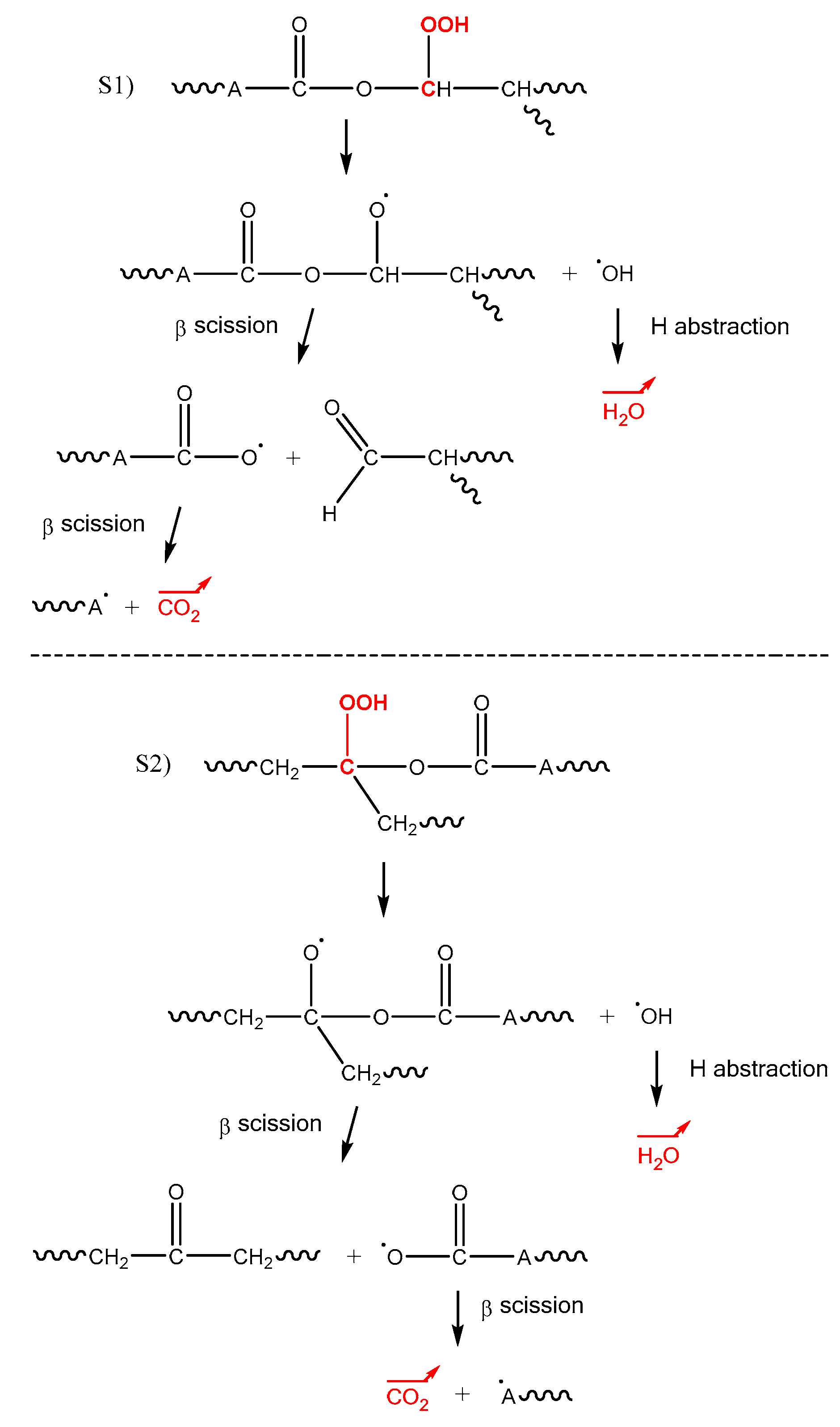
- In general, volatile compounds are formed in the initiation steps of oxidation. As an illustration, mechanistic Scheme 4 reports an example of a chemical event leading to the generation of two volatile compounds (water and carbon dioxide) during the unimolecular decomposition of hydroperoxides POOH, beforehand formed on sites S1 and S2. It should be specified that the rearrangement by β scission of alkoxy radicals PO● occurs preferentially on the weakest bonds of the macromolecular skeleton, i.e., on the O–C bonds, which are characterized by a dissociation energy of only ED ≈ 340 kJ·mol−1 [20].
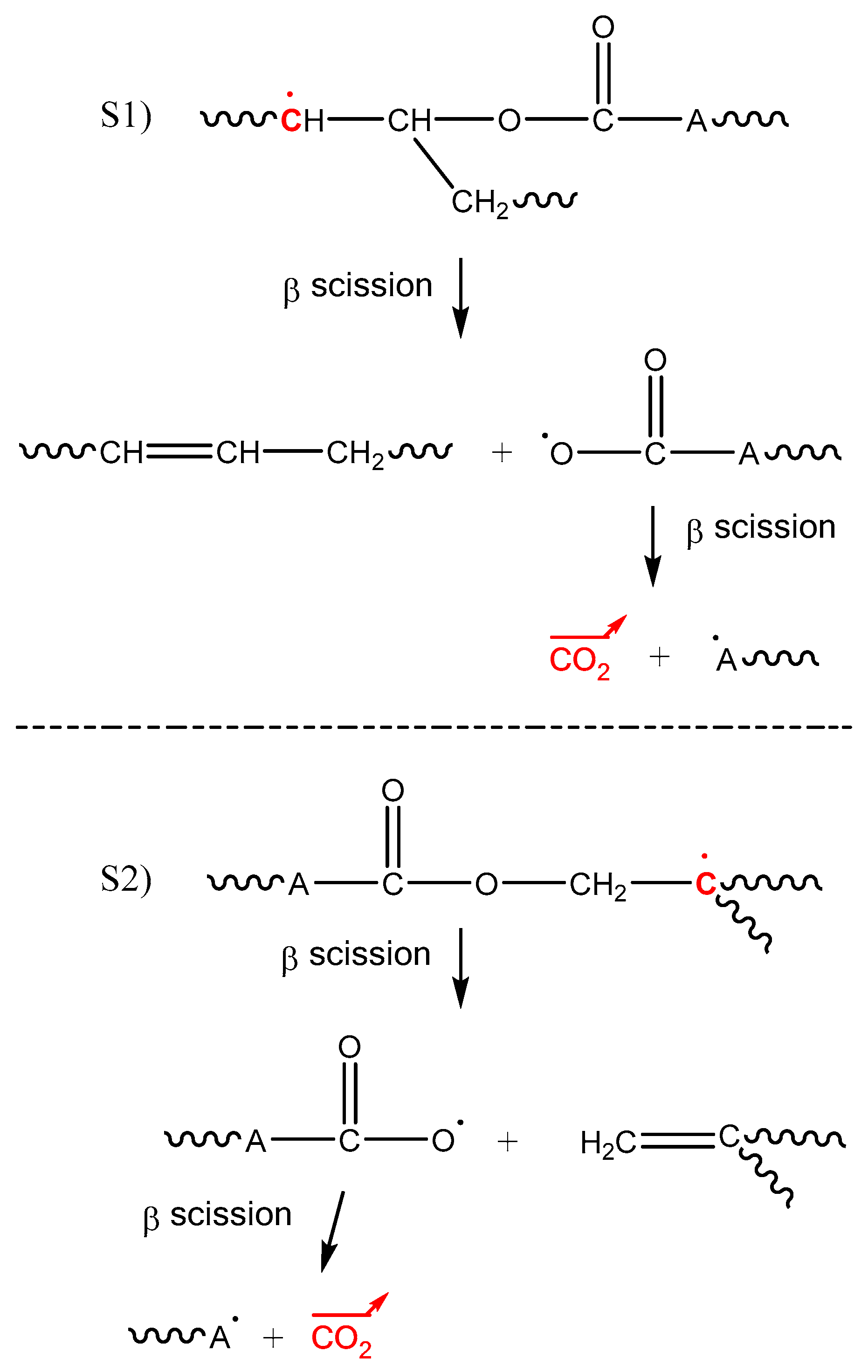
- However, Figure 12b,c shows clearly that an increase of the oxygen partial pressure in the ageing environment (typically from 21% to 100% of the atmospheric pressure) leads to a significant reduction of mass losses. It can be thus concluded that an increase of the oxygen partial pressure favors more the incorporation of oxygen (i.e., mass gain) than the release of volatile compounds (i.e., mass loss). In Figure 12b, a slight hump of mass gain can even be observed between 10 and 20 h of exposure in pure oxygen at 180 °C. This peculiar behavior is presumably due to the existence of additional chemical events generating volatile fragments in oxygen default, which are however totally annihilated in oxygen excess. As an illustration, mechanistic Scheme 5 reports an example of a chemical event leading to the generation of one volatile fragment (carbon dioxide) during the rearrangement by β scission of alkyl radicals P●, beforehand formed on sites S1 and S2. As for alkoxy radicals PO●, this rearrangement occurs preferentially on the O–C bonds of the macromolecular skeleton. Of course, in the presence of oxygen, alkyl radicals P● are quasi-instantaneously transformed into peroxy radicals PO2● propagating oxidation on sites S1 and S2, thus annihilating totally the formation of carbon dioxide.
4. Kinetic Modelling
4.1. Mechanistic Scheme
4.2. System of Differential Equations
4.3. Experimental Checking and Discussion
- Half of the constant rates of the thermal oxidation reaction (from k1u to k4) took the same values as in polyamides [17]. All others (from k5 to k6d) took very close values, thus confirming the initial assumption. The main difference between the oxidative behaviors of epoxy-anhydride matrices and PET is the presence of an additional radical rearrangement. To our knowledge, the value of the corresponding rate constant k2a has never been reported in the literature. The fact that k2a takes a very high value and is independent of temperature clearly indicates the high instability of the alkyl radicals P● involved in the corresponding reaction.
- As for thermolysis, a change in kinetic regime is detected near Tg for thermal oxidation, but only some chemical yields (from γ2 to γ5) are affected. It can thus be concluded that the impact of molecular mobility on the thermal oxidation kinetics is much more reduced than on the thermolysis kinetics.
- Finally, a value higher than the molar mass of carbon dioxide (i.e., 44 g·mol−1) was found for υ1MV1, thus suggesting that volatile fragments heavier than carbon dioxide are also formed during the rearrangement by β scission of alkoxy radicals PO●. A more detailed knowledge of the chemical structure of the epoxy-anhydride matrix would be necessary to identify these volatile fragments and to propose a possible mechanistic scheme for their formation.
4.4. Towards a Nonempirical Prediction of Damage Development
5. Conclusions
Author Contributions
Funding
Conflicts of Interest
References
- Dal Maso, F.; Mézière, J. Calcul des propriétés élastiques des tissus utilisés dans les matériaux composites. Rev. IFP 1998, 53, 857–870. [Google Scholar] [CrossRef][Green Version]
- Belluci, F. Galvanic corrosion between non-metallic composites and metals. II: Effects of area ratio and environmental degradation. Corrosion 1992, 48, 281–291. [Google Scholar] [CrossRef]
- Barjasteh, E.; Bosje, E.J.; Tsai, Y.I.; Nutt, S.R. Thermal ageing of fiberglass/carbon-fiber hybrid composites. Composites A 2009, 40, 2038–2045. [Google Scholar] [CrossRef]
- Tsai, Y.I.; Bosze, E.J.; Barjasteh, E.; Nutt, S.R. Influence of hygrothermal environement on thermal and mechanical properties of carbon fiber/fiberglass hybrid composites. Compos. Sci. Technol. 2009, 69, 432–437. [Google Scholar] [CrossRef]
- Barjasteh, E.; Kar, N.; Nutt, S.R. Effect of filler on thermal aging of composites for next-generation power lines. Composites A 2011, 42, 1873–1882. [Google Scholar] [CrossRef]
- NF EN ISO 178. Plastiques—Détermination des Propriétés en Flexion; AFNOR Editions: La Plaine Saint-Denis, France, 2011. [Google Scholar]
- Colin, X.; Mavel, A.; Marais, C.; Verdu, J. Interaction between cracking and oxidation in organic matrix composites. J. Compos. Mater. 2005, 39, 1371–1389. [Google Scholar] [CrossRef]
- Kondo, K.; Taki, T. Moisture diffusivity of unidirectional composites. J. Compos. Mater. 1982, 16, 82–93. [Google Scholar] [CrossRef]
- Whitcomb, J.; Xiaodong, T. Micromechanics of moisture diffusion in composites with impermeable fibers. J. Compos. Mater. 2002, 36, 1093–1101. [Google Scholar] [CrossRef]
- Tsai, S.W. Composite Design, 4th ed.; Think Composites: Dayton, OH, USA, 1988. [Google Scholar]
- Audouin, L.; Langlois, V.; Verdu, J.; De Bruijn, J.C.M. Role of oxygen diffusion in polymer ageing: Kinetic and mechanical aspects. J. Mater. Sci. 1994, 29, 569–583. [Google Scholar] [CrossRef]
- Defauchy, V.; Le Corre, H.; Colin, X. Simulation of the oxygen permeability of a composite container. J. Compos. Sci. 2018, 2, 21. [Google Scholar] [CrossRef]
- Nait-Ali, L.K.; Colin, X.; Bergeret, A. Kinetic analysis and modeling of PET macromolecular changes during its mechanical recycling by extrusion. Polym. Degrad. Stab. 2011, 96, 236–246. [Google Scholar] [CrossRef]
- Passalacqua, V.; Pilati, F.; Zamboni, V.; Fortunato, B.; Manaresi, P. Thermal degradation of poly(butylene terephthalate). Polymer 1976, 17, 1044–1048. [Google Scholar] [CrossRef]
- Assadi, R.; Colin, X.; Verdu, J. Irreversible structural changes during PET recycling by extrusion. Polymer 2004, 45, 4403–4412. [Google Scholar] [CrossRef]
- Lopez Arraiza, A.; Sarasua, J.R.; Verdu, J.; Colin, X. Rheological behavior and modelling of thermal degradation of poly(ε-caprolactone) and poly(l-lactide). Int. Polym. Process. 2007, 22, 389–394. [Google Scholar] [CrossRef]
- El Mazry, C.; Ben Hassine, M.; Correc, O.; Colin, X. Thermal oxidation kinetics of free additive polyamide 6-6. Polym. Degrad. Stab. 2013, 98, 22–36. [Google Scholar] [CrossRef]
- Colin, X.; Fayolle, B.; Cinquin, J. Nouvelles avancées en modélisation cinétique de la thermo-oxydation des matrices époxy-diamines. Matériaux Tech. 2016, 104, 202. [Google Scholar] [CrossRef][Green Version]
- Korcek, S.; Chenier, J.H.B.; Howard, J.A.; Ingold, K.U. Absolute rate constants for hydrocarbon autoxidation. XXI. Activation energies for propagation and the correlation of propagation arte constants with carbon-hydrogen bond strengths. Can. J. Chem. 1972, 50, 2285–2297. [Google Scholar] [CrossRef]
- Colin, X.; Teyssèdre, G.; Fois, M. Ageing and degradation of multiphase polymer systems. In Handbook of Multiphase Polymer Systems; Boudenne, A., Ibos, L., Candau, Y., Thomas, S., Eds.; John Wiley & Sons Ltd.: Chichester, UK, 2011; Volume 2/2, Chapter 21; pp. 797–841. ISBN 978-0-4707-1420-1. [Google Scholar]
- Colin, X.; Fayolle, B.; Audouin, L.; Verdu, J. About a quasi-universal character of unstabilised polyethylene thermal oxidation kinetics. Polym. Degrad. Stab. 2003, 80, 67–74. [Google Scholar] [CrossRef]
- Van Krevelen, D.W.; Te Nijenhuis, K. Properties of Polymers. Their Correlation with Chemical Structure. Their Numerical Estimation and Prediction from Additive Group Contributions, 4th ed.; Elsevier: Amsterdam, The Netherlands, 2009; Chapter 18; pp. 655–702. ISBN 978-0-08-054819-7. [Google Scholar]
- Stannet, V. Simples gases. In Diffusion in Polymers; Crank, J., Park, G.S., Eds.; Academic Press Inc.: London, UK, 1968; Chapter 2; pp. 41–73. ISBN 0-12-197050-7. [Google Scholar]
- Hairer, E.; Wanner, G. Solving Ordinary Differential Equations II. STIFF and Differential Algebraic Problems; Springer: Berlin, Germany, 1991; Chapter IV; pp. 1–239. ISBN 978-3-540-60452-5. [Google Scholar]
- Pascault, J.-P.; Sautereau, H.; Verdu, J.; Williams, R.J.J. Thermosetting Polymers; Marcel Dekker, Inc.: New York, NY, USA, 2002; Chapter 10; pp. 282–322. ISBN 0-8247-0670-6. [Google Scholar]
- Colin, X. Nonempirical kinetic modelling of non-Fickian water absorption induced by a chemical reaction in epoxy-amine networks. In Durability of Composites in a Marine Environment 2, Solid Mechanics and Its Applications 245; Davies, P., Rajapakse, Y.D.S., Eds.; Springer: Dordrecht, The Netherlands, 2018; Chapter 1; pp. 1–18. ISBN 978-3-319-65144-6. [Google Scholar]
- Bovey, F.A. Effect of Ionizing Radiation on Synthetic and Natural Polymers; Interscience Publishers, Inc.: New York, NY, USA, 1958. [Google Scholar]


| Material | Shape | Size (mm) |
|---|---|---|
| hybrid composite | cylindrical bar | 9.5 × 100 |
| carbon-fiber core | cylindrical bar | 7.0 × 70 |
| - | rectangular bar | 1.2 × 4.2 × 30 |
| - | powder | - |
| glass-fiber shell | powder | - |
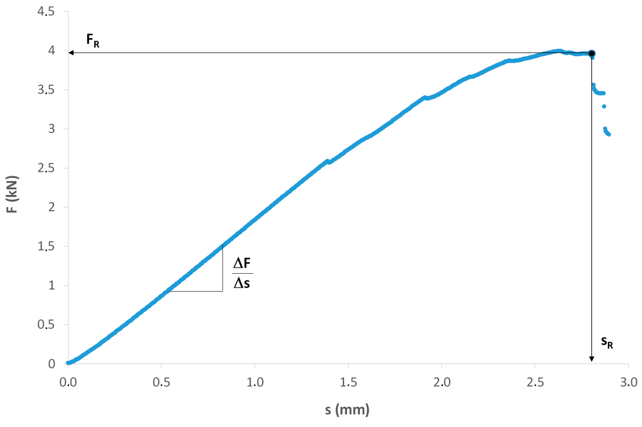
| E (GPa) | σR (MPa) | sR (mm) |
|---|---|---|
| 48.9 ± 0.6 | 838 ± 50 | 2.46 ± 0.20 |
| Material | Direction | Temperature (°C) | TOL (µm) |
|---|---|---|---|
| glass-fiber shell | radial | 180 | 60 |
| - | - | 210 | 60 |
| - | longitudinal | 180 | 450 |
| - | - | 210 | 230 |
| Ageing Conditions | Tg (°C) |
|---|---|
| Virgin rod | 185.7 ± 3.1 |
| 300 h at 180 °C | 142.3 ± 1.9 |
| 33 h at 210 °C | 134.9 ± 1.9 |
| Parameter (unit) | Pre-Exponential Factor | Activation Energy (kJ·mol−1) | Comment | Reference |
|---|---|---|---|---|
| Rate constant | ||||
| k0a (s−1) | 5.8 × 10⁻⁶ | 0 | T ≤ 190 °C | This study |
| 2.5 × 10⁹ | 133 | T ≥ 200 °C | ||
| k0b (l·mol−1·s−1) | 0 | − | − | This study |
| k1u (s−1) | 7.6 × 10¹² | 132 | − | [17] |
| k1b (l·mol−1·s−1) | 1.4 × 10⁹ | 94 | − | [17] |
| k2a (s−1) | 2.4 × 10⁵ | 0 | − | This study |
| k2b (l·mol−1·s−1) | 108 | 0 | − | [17] |
| k3 (l·mol−1·s−1) | 1.8 × 10⁹ | 63 | − | [17] |
| k4 (l·mol−1·s−1) | 8 × 10¹¹ | 0 | − | [17] |
| k5 (l·mol−1·s−1) | 4 × 10¹¹ | 0 | − | This study |
| k6a (l·mol−1·s−1) | 8.4 × 10¹⁶ | 63 | − | This study |
| k6b (s−1) | 9 × 10⁷ | 0 | − | This study |
| k6c (s−1) | 9 × 10⁷ | 0 | − | This study |
| k6d (s−1) | 4.1 × 10¹² | 43 | − | This study |
| Chemical yield | ||||
| υ0 (%) | 6 ± 1 | − | T ≤ 190 °C | This study |
| 20 ± 2 | − | T ≥ 200 °C | ||
| γ1 (%) | 90 | − | − | This study |
| γ2 (%) | 70 | − | T ≤ 190 °C | This study |
| 10 | − | T ≥ 200 °C | ||
| γ4 (%) | 45 ± 5 | − | T ≤ 190 °C | This study |
| 10 | − | T ≥ 200 °C | ||
| γ5 (%) | 45 ± 5 | − | T ≤ 190 °C | This study |
| 10 | − | T ≥ 200 °C | ||
| Molar mass | ||||
| υ0MV0 (g·mol−1) | 5.5 ± 1.3 | − | T ≤ 190 °C | This study |
| 20 ± 1.7 | − | T ≥ 200 °C | ||
| υ1MV1 (g·mol−1) | 48 | − | − | This study |
| υ2MV2 (g·mol−1) | 11 | − | − | This study |
© 2019 by the authors. Licensee MDPI, Basel, Switzerland. This article is an open access article distributed under the terms and conditions of the Creative Commons Attribution (CC BY) license (http://creativecommons.org/licenses/by/4.0/).
Share and Cite
Minard, G.; Colin, X. Thermal Ageing of a Hybrid Composite Rod for Next Generation Overhead Power Lines. J. Compos. Sci. 2019, 3, 103. https://doi.org/10.3390/jcs3040103
Minard G, Colin X. Thermal Ageing of a Hybrid Composite Rod for Next Generation Overhead Power Lines. Journal of Composites Science. 2019; 3(4):103. https://doi.org/10.3390/jcs3040103
Chicago/Turabian StyleMinard, Gaelle, and Xavier Colin. 2019. "Thermal Ageing of a Hybrid Composite Rod for Next Generation Overhead Power Lines" Journal of Composites Science 3, no. 4: 103. https://doi.org/10.3390/jcs3040103
APA StyleMinard, G., & Colin, X. (2019). Thermal Ageing of a Hybrid Composite Rod for Next Generation Overhead Power Lines. Journal of Composites Science, 3(4), 103. https://doi.org/10.3390/jcs3040103