Article

Effect of Internal Structure in the Compression Behavior of Casted Al/LECA Composite Foams

1
CMEMS-UMinho, University of Minho, Campus Azurem, 4800-058 Guimaraes, Portugal
2
MEtRiCS-UMinho, University of Minho, Campus Azurem, 4800-058 Guimaraes, Portugal
*
Author to whom correspondence should be addressed.
J. Compos. Sci. 2018, 2(4), 64; https://doi.org/10.3390/jcs2040064
Submission received: 4 September 2018 / Revised: 8 October 2018 / Accepted: 23 October 2018 / Published: 1 November 2018

Abstract

:
In this paper, low-cost, aluminum-based composite metal foams are produced by the gravity die casting technique using lightweight expanded clay (LECA) as space holders. The influence of the voids generated by LECA particles on the syntactic composite samples density and mechanical behavior is characterized by quasi-static uniaxial compression. It is shown that smaller particles generate higher relative densities and a reduction in the value of densification strain. The use of larger particle diameter promotes an increase in yield strength and a more stable plateau region of the stress–strain curve, leading to higher values of crushing energy absorption. The influence of the internal structure on these experimental results is correlated with elasto-plastic numerical simulations, and it is suggested that a small mismatch in LECA particle diameter is advantageous for enhancing mechanical properties.

1. Introduction

Composite metal foams (CMF) were invented in the late 1920s (e.g., Reference [1]). Since then, they have been the focus of many studies and developments, although it is only recently that they have found relevant industrial application. In fact, metallic foams show an interesting combination of physical and mechanical properties that make them extremely versatile and suitable for applications in areas where high stiffness/specific weight ratio is required [2]. Moreover, the presence of porosities/cavities and the essential inhomogeneity make it possible for them to efficiently absorb impact loads [3], besides revealing excellent acoustic/thermal insulation properties [4] and vibration damping [5]. These properties are attractive in many applications, especially railway, aeronautic, aerospace, and automotive industries, due to their direct influence on energy consumption [6]. Examples of current applications include ultralight panels, energy absorbing structures, heat dissipation media, electrodes for electric batteries, ultrasound deflectors, medical prosthesis, and heat exchangers.
Given that innovation in the design and characterization of these composite materials is still possible, there are no boundaries for their industrial application [7]. However, due to the importance of cell morphology and density (even through the same specimen), modeling approaches may not be able to fully explain the variations in terms of mechanical properties. It is possible that cell volume distribution, changes in rib thickness, and internal void superficial areas need to be considered in terms of structural analysis to understand the deformation behavior in these syntactic foams.
Traditionally, metallic foams are produced using mainly aluminum and magnesium-based alloys. Despite the variety of production methods, there are only two different routes to generate porosity/cavities [8]: self-formation or predesign. In the first case, the porosity forms in a self-evolution process according to physical principles, and the cell structure is difficult to predict and control as they are obtained by injecting gas into a melt. In the case of predesign, the resulting structure is determined by a cell-forming mold, and the foam is obtained by powder metallurgy, sputtering, or investment casting. Each production method covers a characteristic range of density, cell size, and cell topology. In casting, the use of soluble space holders like salt [9] or carbamide [10], which are later removed by immersion in water [11], is necessary. However, there is a recent trend to use low-density, hollow spheres as permanent space holders. These allow very easy control/manipulation of density and pore size/shape, which have a crucial role in the overall mechanical properties [12]. Commonly, steel hollow spheres are employed to accomplish this task due to their inherent structural strength, capability of being densely packed, and regular shape [13]. An alternative route to the use of steel hollow spheres is using lightweight expanded clay (LECA) as permanent space holders [6]. Due to its high porosity, LECA particles possess low density and can be obtained at low cost. Additionally, they are characterized by good thermal and acoustic insulation [14], are chemically inert, and have been proven to be an excellent filler in concrete composites [15]. However, detailed information concerning their mechanical characterization and possible applications is still limited.
In this work, LECA was used as a permanent space holder to produce cast aluminum alloy composite foams. Cylindrical-shaped foam samples were produced using different LECA particle dimensions/densities and submitted to compressive testing to determine the influence of these factors in the overall static mechanical behavior of the foam.

2. Experimental Methodology

2.1. Materials

LECA has a solid clay composition that is filled and expanded with gas bubbles. Its generic clay composition is described in Table 1.
With the objective of determining the role of particle diameter and sample density in the static mechanical behavior of this kind of composite, three sizes of LECA particles with a nominal diameter of 2.02, 3.49, and 5.86 mm were selected (Figure 1).
Table 2 presents the composition of the commercially available AlSi7Mg alloy used in this work as evaluated by optical emission spectrometry.

2.2. Experimental Procedure

Figure 2 shows the experimental set-up used in the present work. The AlSi7Mg was melted and held inside the crucible at 700 °C for 30 min for homogenization. The molten alloy was then degassed by ultrasound for 5 min and refined by addition of 0.2% of master alloy (Al5Ti1B). Melt temperature was controlled within an accuracy of ±2 °C. After 20 min, the alloy was poured in the steel die (40 mm diameter) filled with expanded clay preheated to 350 °C. For all experimental conditions, five samples were poured by gravity casting.

2.3. Samples Characterization

As-cast specimens were machined in dry condition using a EFI DU 25 Lathe machine (Trofa, Portugal), as presented in Figure 3a, in order to obtain a cylindrical geometry (D30 × 40 (mm)). A carbide uncoated (H10) insert was selected for roughing and finishing operations using the depths of cut and feed shown in Table 3. The interrupted cuts at high metal removal rates and the material of the specimens were also relevant factors in the choice of the insert.
Densities of the produced composites were determined by the ratio between volume (evaluated by the measurement of the samples with a Mitutoyo Digimatic 500-170 caliper (Mitutoyo Corporation, Kawasaki, Kanagawa Prefecture, Japan), accuracy 0.01 mm) and mass (evaluated on a VIBRA AJ-620 CE digital scale, Tokyo, Japan, accuracy 0.001 g). Five static uniaxial compression tests for each specimen type were carried out on an AMTEK LR50K Plus universal testing machine (Meerbusch, Germany) with a crosshead speed of 1 mm/min using 50 N prestress and stopped after reaching 50 kN load. During testing, displacements and loads were recorded to calculate the instant values of sample strain and stress.

3. Results and Discussion

Figure 3b shows the machining of the samples to a final cylindrical shape. The aluminum alloy fraction revealed a smooth surface finishing, while the LECA fraction displayed rough cavities due to their fragile collapse during both casting and the machining process. Although a steel mesh was placed during the filling process to coerce the particles (see Figure 2), their low density (0.27–0.55 g/cm3)—when compared with liquid aluminum alloy (2.40 g/cm3)—and the overall turbulence during casting generated a mixed open/closed cellular structure. In Figure 3b,c it can be observed that particles and surface tension promoted an open cell structure, while the ones apart made a closed cell. In fact, before pouring, the LECA particles were in contact, thus promoting an open cell structure. However, due to turbulence and density mismatch, some of them could move and individualize. If the compaction loads were not able to compensate these effects, there was a tendency to form closed cell cellular structures.
The final specimen dimensions, weight, and calculated densities are presented in Figure 4 and Figure 5. It can be observed that sample density depended on the diameter of the LECA particles, with the lower diameters leading to higher samples density.
An initial theoretical stacking proposal of the LECA particles is suggested in Figure 6a, where the fundamental area between particles may be described by an isosceles triangle. However, this principle was changed to a real stacking of LECA particles after the aluminum infiltration by cutting the produced samples and calculating the areas of the scalene triangles formed by adjacent particles. From this analysis, the relationship between triangle areas and average side lengths was evaluated, as shown in Figure 6b. Given the higher ratios between areas and lengths in smaller particles, there was a slightly higher concentration of aluminum alloy in the particle–particle boundaries, increasing the wall thickness, which increased the density of the samples. Additionally, the higher standard deviation in samples with higher diameters was correlated with the higher sample diameter mismatch, as shown in Figure 1.
Figure 7 shows the average stress–strain behavior under uniaxial compression of samples with different LECA particle diameters. It suggests that the particle diameter and, by consequence, the density of the samples, had a primary role in the mechanical performance of this cellular material. Nevertheless, every tested configuration was able to replicate a typical three-stage curve of a foam structure under compression, with pronounced linear elastic, plateau, and densification regions.
On an initial stage, the sample was constrained by a preload (Figure 8a), which was negligible and corresponded to point (a) in Figure 7. As the loads imposed on the samples increased, there was a proportional linear increase in stress values until yielding occurred (point (b) in Figure 7), as shown in Figure 8b. A further increase in the loading led to the internal cellular structure starting to progressively collapse in a plateau region. As the strain increased, the internal aluminum walls collapsed due to the combined complex loading states (point (c) of Figure 7 and Figure 8) and, although the values of strain were increased, the stress was fairly linear. During this period, the internal structure of the LECA particles was crushed by severe aluminum plastic wall deformation. By this phase, the metallic foam completely compromised their initial spherical cell stable configuration. The increase in the referred compression strain implied that the original cellular LECA internal structure was lost and that the remaining clay densified as the aluminum cells tended to close (Figure 7 and Figure 8d).
From Figure 7 and Figure 8, it is possible to understand the static mechanical behavior of this kind of metallic foam. Figure 9 suggests that an increase in particle diameter generated an elevation in yield strength, although the samples’ absolute and relative densities decreased (see Figure 5 and Figure 6).
In order to justify this increase in yield strength when the overall density was increased, three fundamental two-dimensional unitary cells representing the aluminum/LECA foam were modeled (Figure 10a). These fundamental models were composed of LECA particles with 3.5 mm diameter. The regular rib model represented the fundamental situation in which stacking promotes a regular area where particles are regularly spaced and may be correlated with the lower particle diameters, as shown in Figure 1. Both “thin” and “thick” rib models represented variations in the periodicity of the fundamental two-dimensional cells, being associated with the standard deviations in higher particle diameters shown in Figure 1. These referred models were subjected to a uniaxial compression simulation using finite element analysis (FEA) (Figure 10b); the details of which are presented in Table 4. Fundamentally, these simulations allowed the determination of reaction loads and deformations in the models that were used to calculate the apparent stresses and strains in the referred models.
From these simulations, it was possible to determine the apparent stress–strain curves of the referred models (Figure 11a). Based on these curves, the apparent yield strength (Figure 11b) of the models could be determined by observing the deviation from the numerical results from the initial elastic proportional plot.
Based on the results shown in Figure 11b, it was possible to determine that the deviations from the theoretical isosceles triangles between particles might generate a variation in the values of yield strength. However, as shown, this deviation of the isosceles model, which is typical of the higher LECA diameters due to particle diameter mismatch (Figure 1 and Figure 4), might increase the average values of yield strength.
The suggested hypothesis was supported by the analysis of the plateau region. Given the higher average yield strength ability of these thick/thin ribs, the structure with higher particle diameter provided a near constant stress plateau (Figure 9), according to Equations (1)–(3), due to a well distributed thru-height deformation.
= 2.0   mm     σ = 58.67 ε + 9.80     R 2 = 0.99
= 3.5   mm     σ = 15.06 ε + 17.54     R 2 = 0.78
= 6.0   mm     σ = 29.52 ε + 21.01     R 2 = 0.81
In samples with smaller particles diameter, a more localized deformation was promoted due to the lower yield strength, and the different cellular layers progressively collapsed, generating a gradual increase in sample stiffness that was proved by the high slope in the plateau equation of these samples. This steady densification generated a smooth collapse, as shown by the data concerning the standard deviation of Equations (1)–(3) relatively to the established experimental plateaus of Figure 7.
In terms of densification, smaller particles promoted an increase in density and, as a consequence, the overall densification strain was reduced. Given that the cellular structure was only able to collapse until all LECA-filled cells were crushed, the relative amount of these structures decreased, as did the allowable admitted deformation for this process to occur.
Finally, it was apparent that an increase in particle size was advantageous to elevate the crushing energy until the densification strain. The elevation of yield strength and a more linear plateau promoted a more efficient route to absorb crushing energy.

4. Conclusions

In the present work, the role of LECA particle diameter in the overall Al composite density and mechanical behavior was studied. The main conclusions to be draw from the study are as follows:
(1)
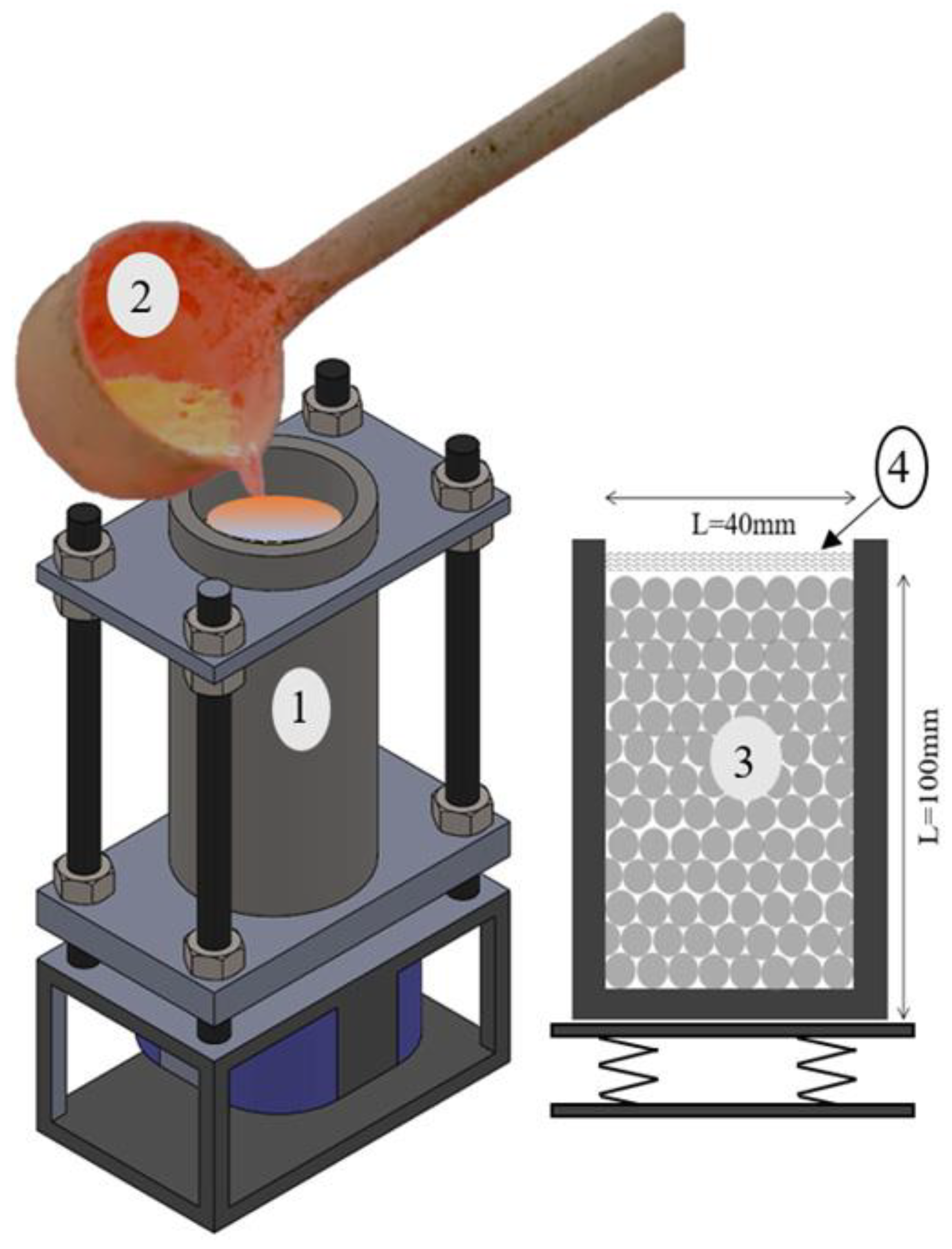
Gravity casting can be a successful route to manufacture low-cost cellular structures.
(2)
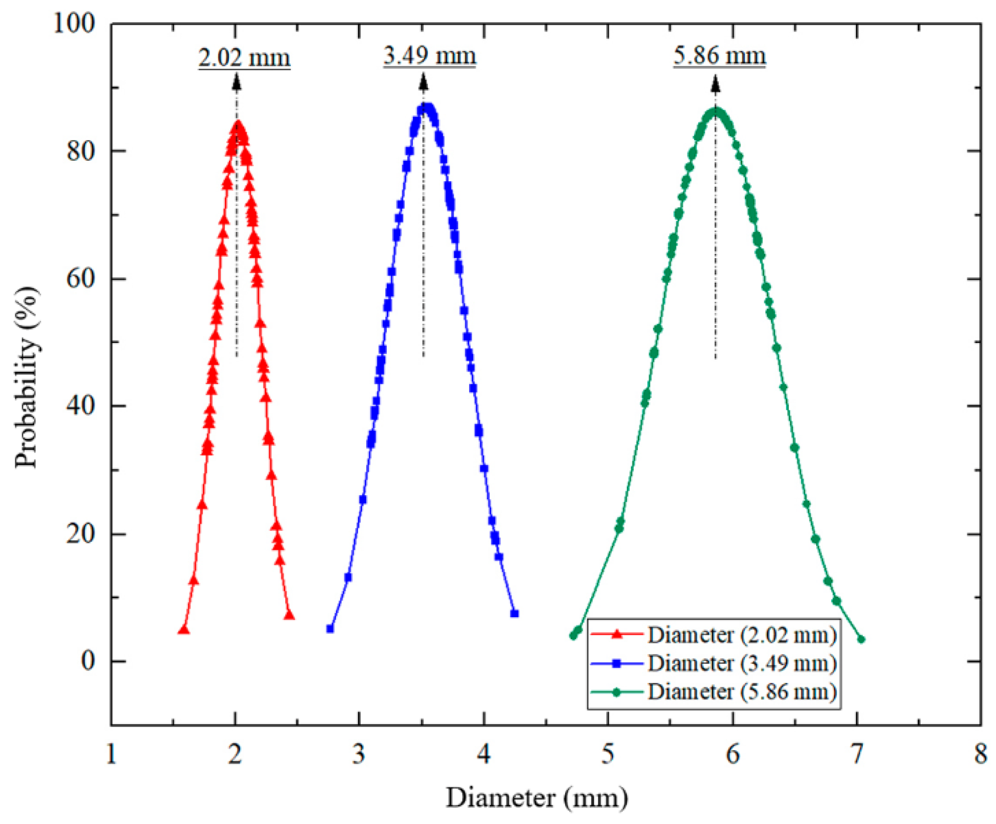
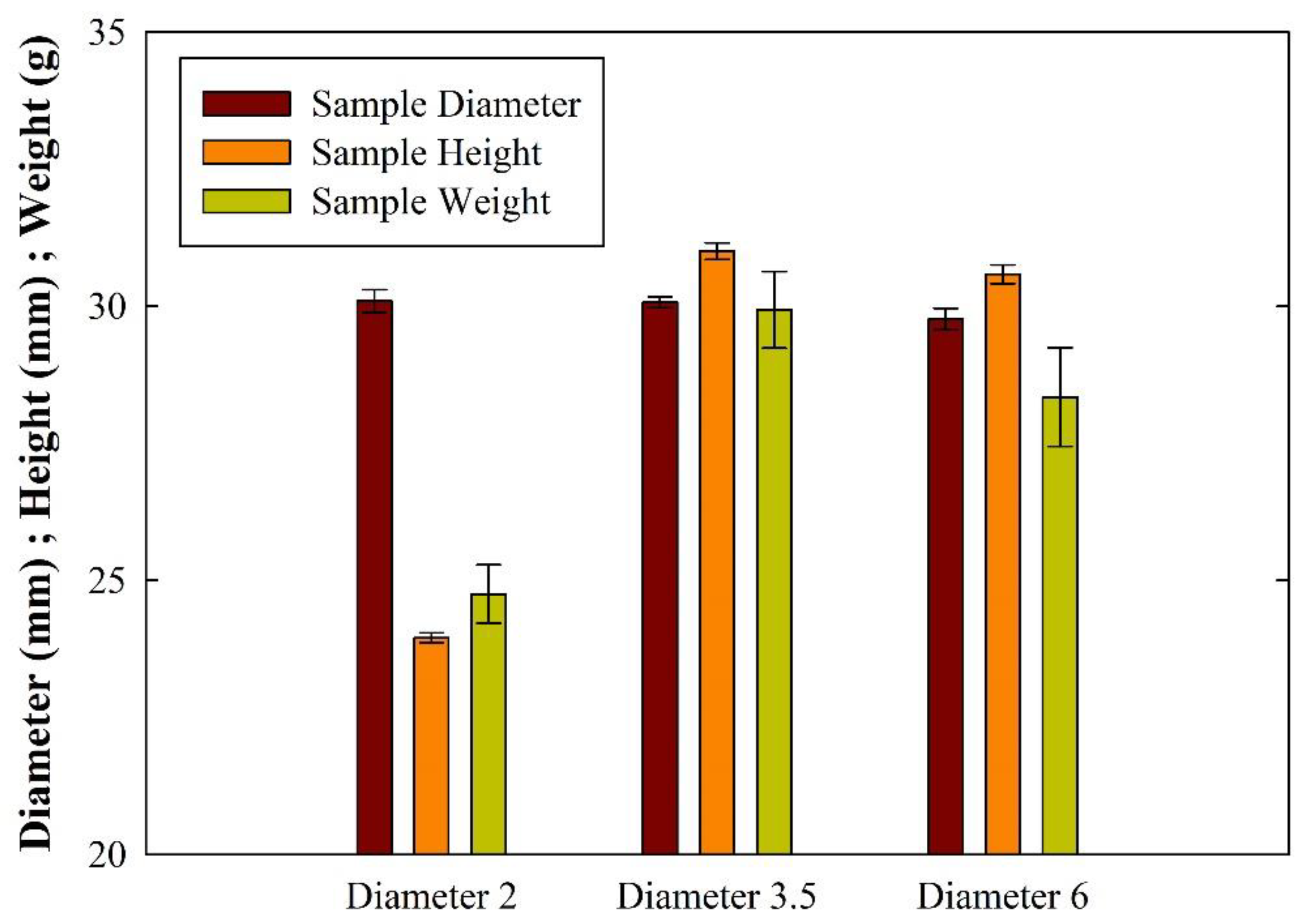
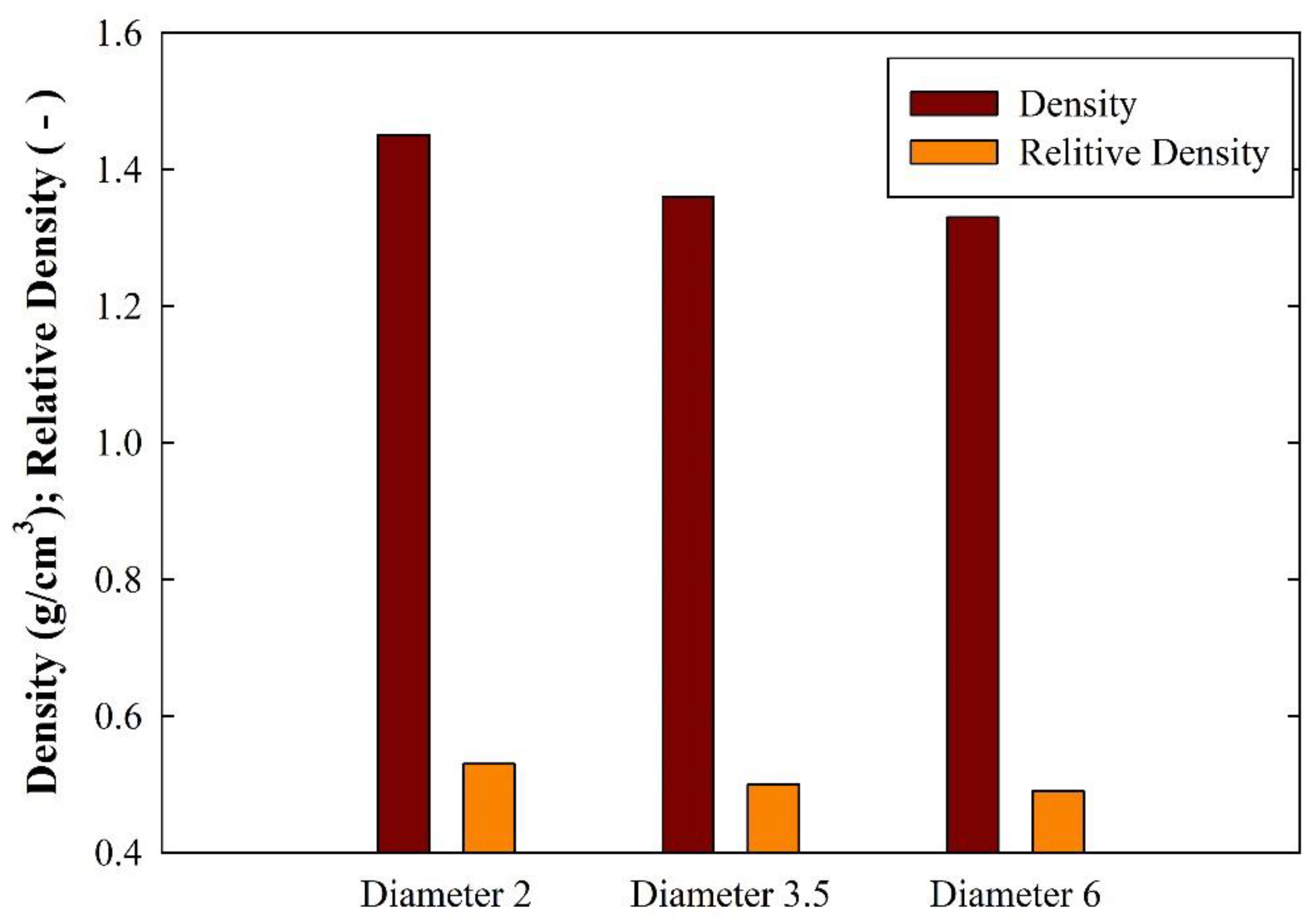
The different LECA particle diameters have a predominant role in the density and overall mechanical behavior of the final composites. Experimental results showed that smaller particles generated higher densities and consequently resulted in a reduction in the value of strain densification.
(3)
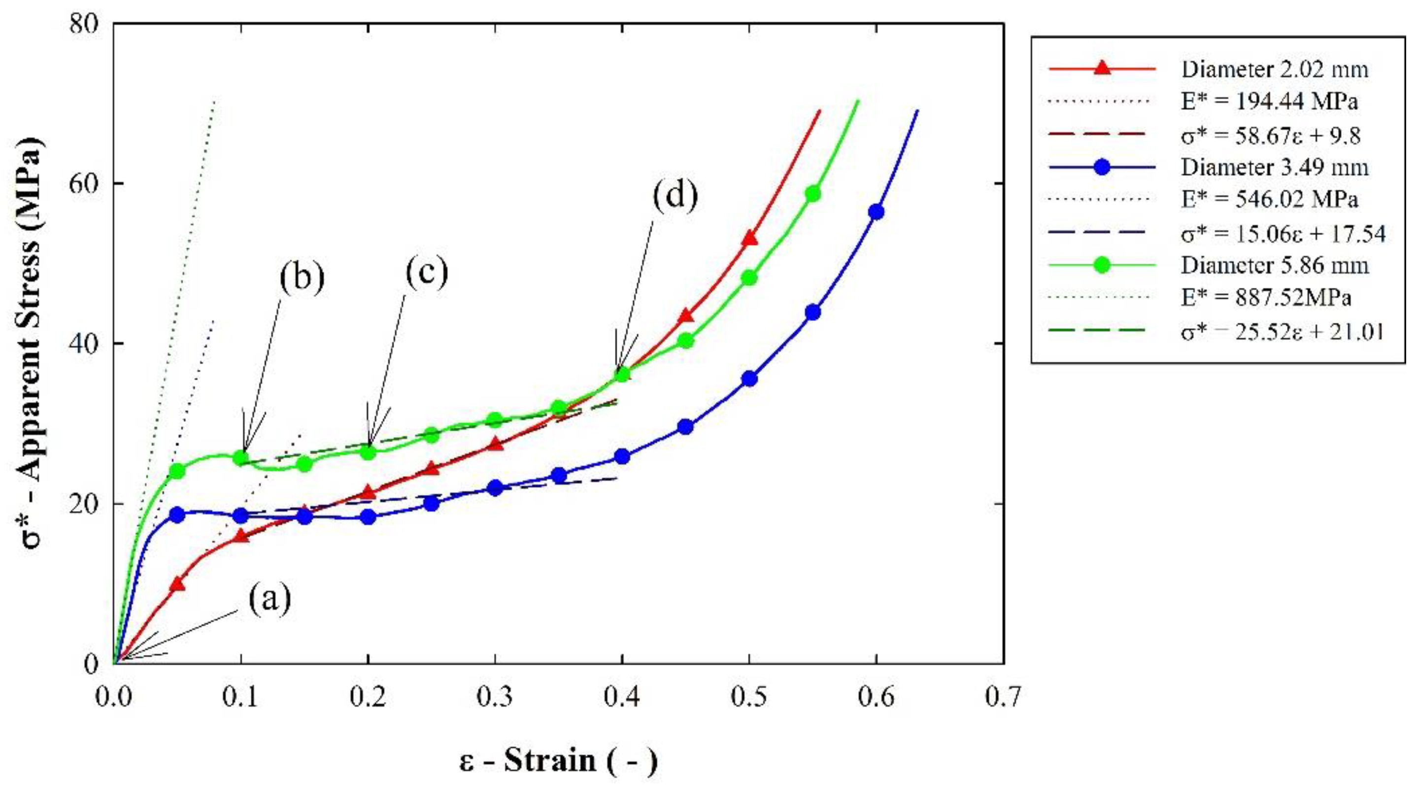
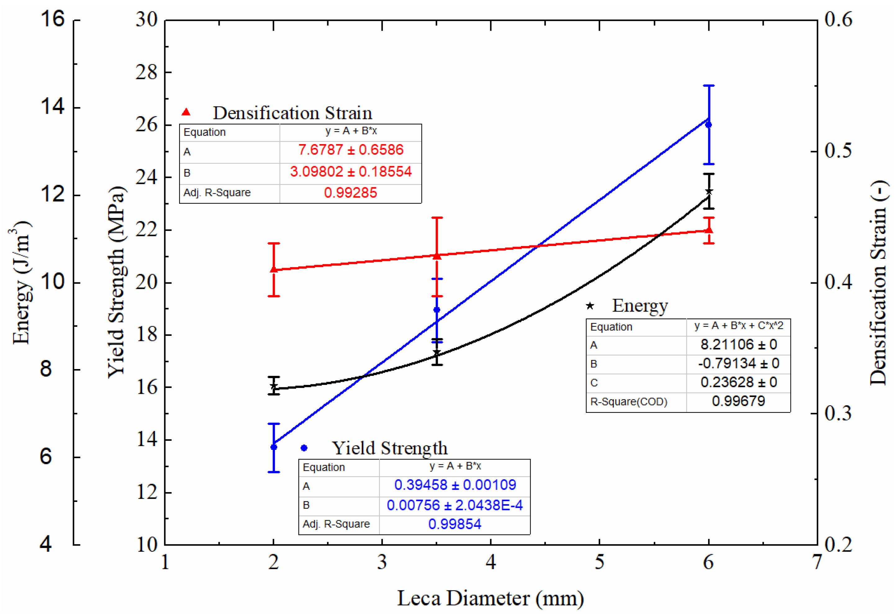
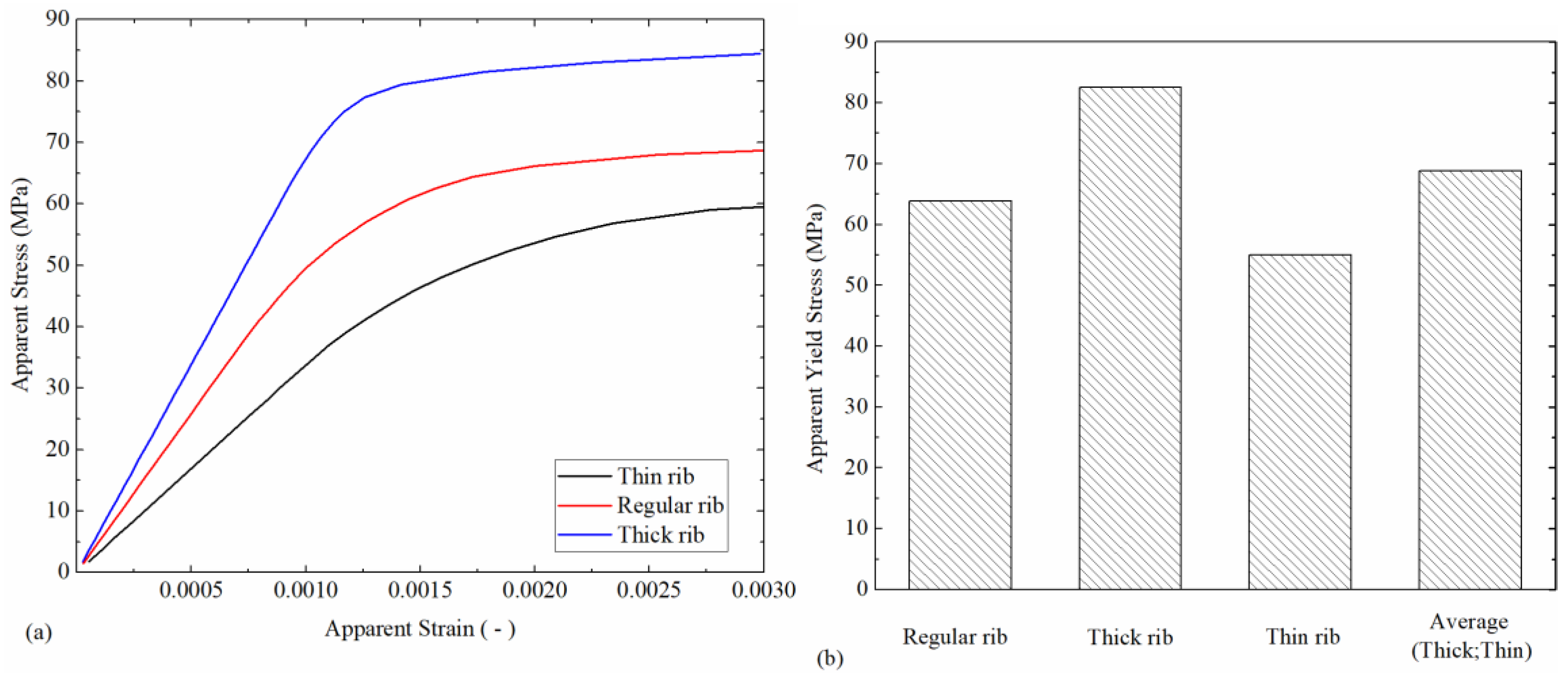
The use of higher particle diameter generates an elevation in yield strength and a more constant stress value during the plateau region. Furthermore, the referred mechanical characteristics allow higher values of crushing energy absorption in more elevated particle diameters.
(4)
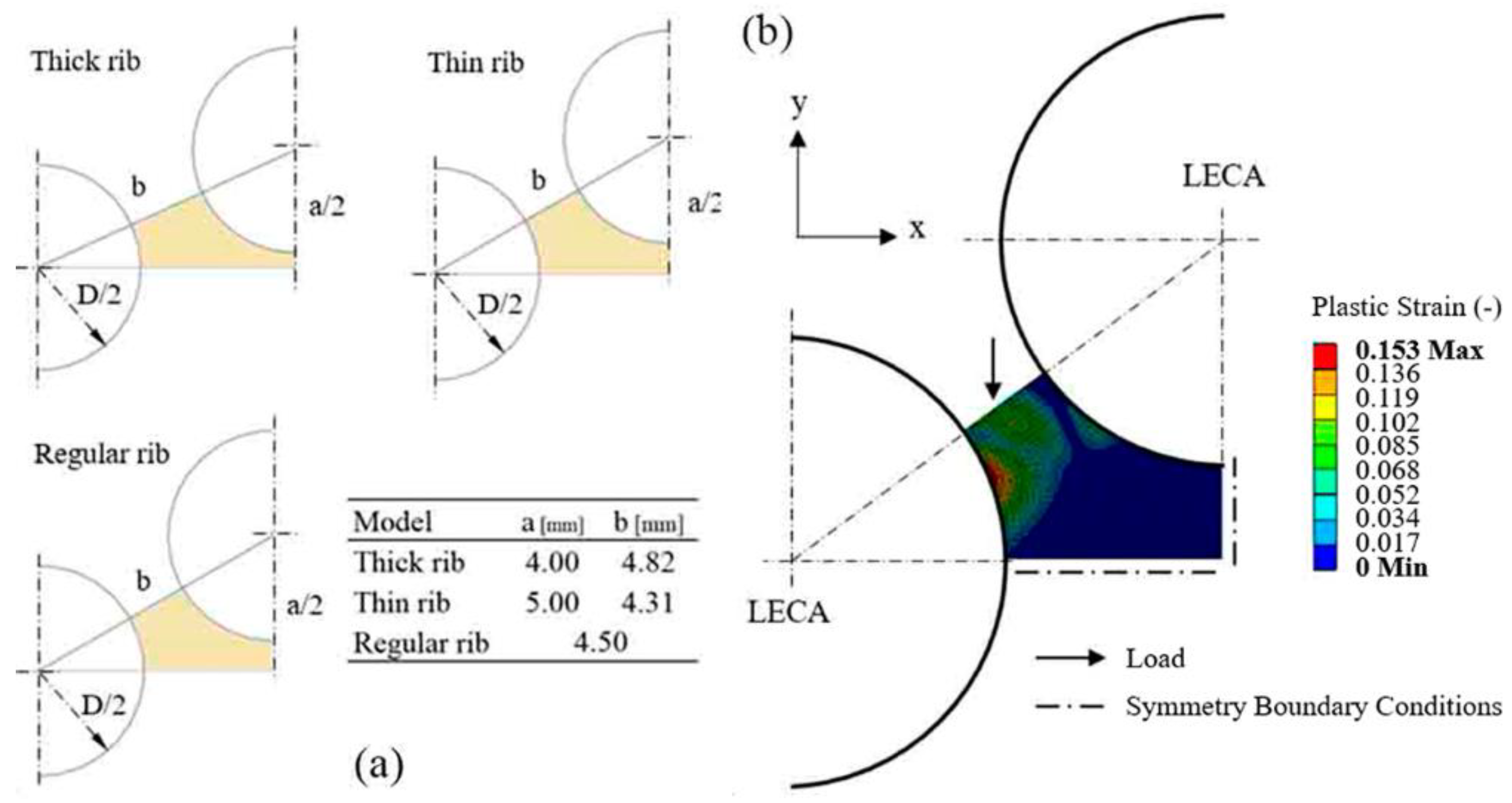
The role of internal structure in the overall mechanical behavior of these composites was analyzed by an elasto-plastic numerical model. It is suggested that a small mismatch in LECA particle diameter is advantageous to enhance mechanical properties.

Author Contributions

Conceptualization, H.P. and V.H.C.; Methodology, J.B.; Resources, H.P.; Data Curation, V.H.C.; Writing-Original Draft Preparation, H.P. and V.H.C.; Writing-Review & Editing, H.P., V.H.C. and J.B.

Funding

This work is supported by the research doctoral grant PD/BD/114096/2015 and postdoctoral grant SFRH/BPD/76680/2011 through Portuguese National Funding Agency for Science (FCT). In addition, this work is supported by FCT with the reference project UID/EEA/04436/2013 and by FEDER funds through the COM-PETE 2020 with the reference project POCI-01-0145-FEDER-006941.

Conflicts of Interest

The authors declare no conflicts of interest.

References

  1. Meller, M.A. Produit Métallique Pour L’obtention D’objets Laminés, Moulés Ou Autres, Et Procédés Pour Sa Fabrication. French Patent 615147, 30 December 1926. [Google Scholar]
  2. Czekanski, A.; Elbestawi, M.A.; Meguid, S.A. On the FE modeling of closed-cell Aluminum Foam. Int. J. Mech. Mater. Des. 2005, 2, 23–34. [Google Scholar] [CrossRef]
  3. Chen, S.H.; Chan, K.C.; Wu, F.F.; Xia, L. Achieving high energy absorption capacity in cellular bulk metallic glasses. Sci. Rep. 2015, 5, 10302. [Google Scholar] [CrossRef] [PubMed] [Green Version]
  4. Dyga, R.; Witczak, S. Investigation of Effective Thermal Conductivity Aluminum Foam. Proc. Eng. 2012, 42, 1088–1099. [Google Scholar] [CrossRef]
  5. Lamanna, E.; Gupta, N.; Cappa, P.; Oliver, M.; Strbik, I.I.I.; Cho, K. Evaluation of the dynamic properties of an aluminum syntactic foam core sandwich. J. Alloys Compd. 2017, 695, 2987–2994. [Google Scholar] [CrossRef]
  6. Bonani, B.B.; Khabushan, J.K.; Kahani, R.; Raouf, A.H. Fabrication of metallic composite foam using ceramic porous spheres “Light Expanded Clay Aggregate” via casting process. Mater. Des. 2014, 64, 310–315. [Google Scholar]
  7. García-Moreno, F. Commercial Applications of Metal Foams: Their Properties and Production. Materials 2016, 9, 85. [Google Scholar] [CrossRef] [PubMed]
  8. Banhart, J. Light-Metal Foams—History of Innovation and Technological Challenges. Adv. Eng. Mater. 2013, 15, 82–111. [Google Scholar] [CrossRef]
  9. Vesenjak, M.; Sulong, M.A.; Opara, L.V.; Borovinsek, M.; Mathier, V.; Fiedler, T. Dynamic compression of aluminium foam derived from infiltration casting of salt dough. Mech. Mater. 2016, 93, 96–108. [Google Scholar] [CrossRef]
  10. Bafti, H.; Habibolahzadeh, A. Compressive properties of aluminum foam produced by powder-Carbamide spacer route. Mater. Des. 2013, 52, 404–411. [Google Scholar] [CrossRef]
  11. Soni, B.; Biswas, S. Development of Al Foams by a Low-cost Salt Replication Method for Industrial Applications. Mater. Today Proc. 2015, 2, 1886–1891. [Google Scholar] [CrossRef]
  12. Nayyeri, M.; Mirbagheri, M.; Fatmehsari, D. Numerical evaluation of the stacking effect of spheres on the mechanics of tailor-made aluminum foams. Comp. Struct. 2017, 159, 316–326. [Google Scholar] [CrossRef]
  13. Avila, M.G.; Rabiei, A. Effect of Sphere Properties on Microstructure and Mechanical Performance of Cast Composite Metal Foams. Metals 2015, 5, 822–835. [Google Scholar] [CrossRef] [Green Version]
  14. Ardakani, A.; Yazdani, M. The relation between particle density and static elastic moduli of lightweight expanded clay aggregates. Appl. Clay Sci. 2014, 93–94, 28–34. [Google Scholar] [CrossRef]
  15. Hubertová, M.; Hela, R. Durability of Lightweight Expanded Clay Aggregate Concrete. Proc. Eng. 2013, 65, 2–6. [Google Scholar] [CrossRef]
Figure 1. Normal distribution of lightweight expanded clay (LECA) particles.
Jcs 02 00064 g001
Figure 2. Composite production set-up. (1) Metallic mould; (2) aluminum alloy melt; (3) LECA particles; (4) steel net.
Jcs 02 00064 g002
Figure 3. Composite sample representation: (a) machining process; (b) composite sample representation; (c) particle interaction schematics.
Jcs 02 00064 g003
Figure 4. Produced sample dimensions.
Jcs 02 00064 g004
Figure 5. Produced sample densities.
Jcs 02 00064 g005
Figure 6. LECA stacking analysis: (a) Theoretical and real area calculation; (b) dimension ratio results.
Jcs 02 00064 g006
Figure 7. Compressive stress–strain behavior for different particle diameters.
Jcs 02 00064 g007
Figure 8. Example of sample behavior during uniaxial compression test: (a) pre-stress; (b) plastic collapse; (c) deformation during plateau stress; and (d) densification.
Jcs 02 00064 g008
Figure 9. Detailed results of the uniaxial compression testing.
Jcs 02 00064 g009
Figure 10. Representation of the simulation (a) models and (b) boundary conditions.
Jcs 02 00064 g010
Figure 11. FEA results: (a) model apparent stress strain curves; and (b) apparent yield strength.
Jcs 02 00064 g011
Table 1. Lightweight expanded clay (LECA) chemical composition.
ElementsSiO2Al2O3Fe2O3K2OCaCO3MgOSOther
w (%)61.9517.918.183.905.391.380.57Balance
Table 2. Aluminum alloy chemical composition.
AlloyChemical Composition (wt %)
SiFeMgCuMnZnTiAlRes.
AlSi7Mg7.440.130.580.070.070.050.11Bal.0.12
Table 3. Sample machining details.
SpecificationValue
InsertCarbide (Uncoated H10)
Rotational speed, N (rpm)1200
Depth of cut, ap (mm)0.50
Cutting speed, v (m/min)60.00
Feed, fa (mm/rev)0.10
Table 4. Finite element analysis (FEA) inputs details.
ModelStatic Structural—Nonlinear Isotropic
Material (Cast Aluminum Alloy)Young’s Modulus (GPa)70
Poisson’s Ratio (-)0.33
Tangent Modulus (GPa)0.5
Yield Strength (MPa)197
MeshingElement TypePLANE183
DescriptionQuadratic—High order 2d—8 noded
SolverSparse Direct Equation Solver
Simulation OutputsVertical loads and displacement

