Article

Geopolymer-Derived Aluminosilicate Matrix Composites Reinforced with Continuous Inconel 601 Fibers: Tensile Properties and Thermo-Oxidative Behavior

by
Michal Jasiczek
1,*,
Marcelina Bobrowska
1,* and
Arnold Jedral
2
1
GE Aerospace, al. Krakowska 110/114, 02256 Warsaw, Poland
2
Łukasiewicz Research Network-Institute of Aviation, al. Krakowska 110/114, 02256 Warsaw, Poland
*
Authors to whom correspondence should be addressed.
J. Compos. Sci. 2026, 10(9), 501; https://doi.org/10.3390/jcs10090501
Submission received: 27 July 2026 / Revised: 11 September 2026 / Accepted: 17 September 2026 / Published: 19 September 2026
(This article belongs to the Topic Advances in Fiber-Reinforced Composites)

Abstract

Continuous-fiber composite laminates based on Inconel 601 reinforcement and a geopolymer-derived aluminosilicate matrix were fabricated using a slurry-impregnation/prepreg processing route followed by low-temperature consolidation and post-curing. The objective of this study was to evaluate the flexural and tensile properties, as well as the thermo-oxidative behavior, of this composite system. The as-fabricated laminates exhibited a bulk density of 4.05 ± 0.08 g/cm3 and an apparent porosity of 24.88 ± 0.62%. Tensile testing showed measurable mechanical properties for both unidirectional and balanced laminate architectures. The [0]8 laminates exhibited tensile strengths of approximately 327–365 MPa from room temperature to 538 °C, while the [0/90]2S laminates showed a decrease in room-temperature tensile strength, consistent with the lower fraction of load-bearing 0° fibers. Thermo-oxidative exposure in air at 538 °C for 336 h produced no measurable reduction in room-temperature flexural strength; accordingly, accelerated oxidation tests were conducted at higher temperatures to promote observable degradation. These tests indicated a transition from limited oxidation at 538 °C to more uniform oxidation at intermediate temperatures and to more aggressive, localized fiber attack at 816 °C. These results suggest that the material system, although still in its developmental stage, is a candidate for further development toward intermediate-temperature applications (approximately 300–600 °C).

1. Introduction

Continuous-fiber-reinforced inorganic-matrix composites have been widely explored for applications that must sustain load at temperatures beyond the limits of polymer-matrix systems. Glass- and glass–ceramic-matrix composites have demonstrated elevated-temperature capability together with quasi-ductile fracture behavior; however, their broader adoption has historically been hindered by complex high-temperature processing and associated cost. In parallel, geopolymers, defined as alkali- or acid-activated aluminosilicate binders, offer a low-temperature processing route analogous in some respects to resin impregnation, thereby suggesting a potential path toward lower-cost continuous-fiber composites for intermediate-temperature applications (approximately 300–600 °C) [1].
Geopolymers develop three-dimensional Si-O-Al networks that can cure near ambient temperature and retain mechanical integrity at temperatures up to and beyond 1000 °C [1,2,3,4]. Their processing resembles that of thermoset polymers in that liquid precursors can be used to impregnate fiber preforms and then cured without the melting, sintering, or hot-pressing steps typically associated with conventional ceramic-matrix processing [1,2,5]. Fiber reinforcement can markedly improve strength and toughness, and carbon- or SiC-fiber-reinforced geopolymers have therefore been proposed for structural and fire-resistant components in applications where polymer-matrix composites are unsuitable [1,3,5,6,7,8].
In contrast, continuous-fiber-reinforced glass- and glass–ceramic-matrix composites, including borosilicate glass-ceramics, barium strontium aluminosilicate (BSAS/BAS), and calcium aluminosilicate (CAS) systems, are commonly produced by powder-based routes. These typically involve synthesis of a melt-derived glass or glass–ceramic powder, formulation of a slurry, infiltration into fiber preforms, drying, and subsequent consolidation by sintering or hot pressing at temperatures often exceeding 1300 °C under substantial pressure [9,10,11,12,13]. SiC-fiber-reinforced celsian (BSAS) composites produced by slurry infiltration and hot pressing illustrate the capabilities of this class of material, including nearly fully dense matrices, damage-tolerant failure modes, and high strength at temperatures above 850 °C [13]. Similar approaches for borosilicate–ZrO2 and related glass–ceramic matrices have also yielded strong and tough ceramic-matrix composites, but only through demanding multistep processing and, in many cases, the use of fiber coatings to preserve damage tolerance, thereby increasing overall system complexity [13].
Despite decades of research and many promising demonstrations, published reviews continue to indicate that glass- and glass–ceramic-matrix composites face challenges that limit wider commercial implementation [14]. The literature includes numerous prototype components and candidate applications in aerospace, energy, and chemical-processing sectors, but broad industrial deployment appears to remain limited relative to established polymer-matrix composites and SiC/SiC ceramic-matrix composites [15,16]. This limited uptake is commonly associated with high processing cost, difficulties in scale-up, and challenges associated with manufacturing complex geometries [14].
In practice, SiC/SiC ceramic-matrix composites have emerged as the most mature high-temperature CMC technology for gas-turbine and other extreme-environment applications. SiC/SiC composites produced by chemical vapor infiltration (CVI), reactive or melt infiltration (RMI/MI), polymer infiltration and pyrolysis (PIP), or hybrid combinations of these routes are now widely recognized as key materials for high-efficiency aircraft engines and other harsh-environment systems [15,17,18,19,20,21]. CVI SiC/SiC and MI SiC/SiC composites provide high strength and damage tolerance at temperatures where superalloys require substantial cooling, and MI SiC-based CMCs have been successfully commercialized for aircraft-engine components [15,21]. Well-known examples include SiC/SiC components such as high-pressure turbine shrouds in the CFM LEAP engine and multiple CMC components in the GE9X engine [15].
Manufacturing routes for SiC/SiC composites have matured to the point that, although they remain complex and expensive, they are viable for high-value industrial components. CVI can produce high-quality, near-net-shape SiC matrices, but it is inherently slow and costly [17,18,20]. Reactive melt infiltration can rapidly produce dense matrices, although it may leave residual silicon and can introduce risk of fiber damage [20,21]. Hybrid processing approaches combining CVI, PIP, and RMI are being actively explored to balance porosity, microstructural control, cycle time, and cost, and are widely discussed as promising routes for industrial SiC/SiC manufacturing [17,19,20]. In addition, advanced fiber architectures, including three-dimensional woven and braided preforms, together with process innovations such as spray-dried powders, binder-jetted preforms, and optimized CVI kinetics, continue to improve manufacturability and performance [17,20,21].
Taken together, the present landscape shows a clear divergence in industrial trajectories among ceramic-matrix composite systems. Glass- and glass–ceramic-matrix composites have demonstrated attractive thermomechanical behavior, but their reliance on powder-slurry infiltration and high-temperature sintering or hot-pressing steps has limited broader adoption beyond development and niche applications [10,11,12,14]. By contrast, SiC/SiC CMCs, particularly those produced by CVI, MI/RMI, and hybrid CVI + PIP or PIP + RMI routes, have achieved demonstrable industrial traction in aerospace because their manufacturing technologies, while still sophisticated, have proven to be viable for scale-up and compatible with complex component geometries. In addition, these material systems provide exceptional thermal and environmental capability at temperatures relevant to advanced turbine operation [15,17,18,19,20,21,22].
Oxide CMCs based on alumina- or mullite-fiber reinforcement provide an alternative to SiC/SiC systems in oxidizing environments because of their favorable oxidation resistance and thermomechanical stability [23,24]. They continue to be regarded as promising candidates for elevated-temperature applications [25]. However, their adoption has also remained limited relative to non-oxide CMCs, in part because they still require engineered continuous oxide fibers, which contribute substantially to total system cost. As a result, these materials are generally considered for a narrower range of applications in which specific functional or enabling attributes justify their use. For applications driven primarily by weight reduction, oxide CMCs must also compete directly with Ni-based superalloys, for which weight-cost tradeoffs often hinder broader implementation [23,25,26].
These considerations motivate the exploration of alternative composite concepts in which geopolymer-derived aluminosilicate matrices are combined with lower-cost continuous reinforcements for sustained use at intermediate temperatures. In the present work, geopolymer-derived composites reinforced with continuous fibers of the commercially available nickel-based alloy Inconel 601 are investigated. Inconel 601 was selected because of its commercial availability in fiber tow form, oxidation resistance, retention of useful tensile and creep-rupture properties up to and above 540 °C, together with good resistance to neutral and alkaline environments, including hydroxide-containing media [27,28]. Taken together, these attributes indicate that Inconel 601 is a potential reinforcement candidate for geopolymer-based composite systems, in which both intermediate-temperature mechanical stability and compatibility with alkaline processing conditions inherent to geopolymer composite fabrication are important. The objective of this study is to evaluate the feasibility of this material system through characterization of laminate density, tensile-dominated mechanical properties, and the effects of prolonged elevated-temperature exposure on property retention and microstructural evolution during accelerated oxidation testing. Comparatively limited information is available on continuous-fiber laminate systems combining metallic reinforcement with a geopolymer-derived aluminosilicate matrix.

2. Materials

The material investigated in this study was a geopolymer-derived aluminosilicate matrix composite reinforced with continuous fibers acquired commercially as a development product made of Inconel 601 alloy (Bekaert, Zwevegem, Belgium) in the end-drawn condition. The fibers were supplied in tow form with an equivalent diameter of 12 µm and were used as received, with no sizing applied to the fiber surface. Fibers were used as continuous reinforcement in the manufacture of composite laminates for density measurements, mechanical testing, and elevated-temperature exposure studies.
The matrix was produced from a precursor system comprising a commercial-grade kaolinite source together with high-purity laboratory-grade colloidal silica and silicate and hydroxide sources. No fillers were used in the matrix formulation. Although the exact compositional ratios and detailed slurry formulation are proprietary and therefore not disclosed, the resulting material system consisted of a geopolymer-derived aluminosilicate matrix reinforced with continuous Inconel 601 fibers.

3. Composite Fabrication

Composite panels used in this work were manufactured using a slurry-impregnation and drum-winding prepreg process, in which continuous fiber tow was passed through a slurry bath and then wound onto a drum. The wound material was subsequently cut and separated to produce prepreg sheets for laminate lay-up. Slurry uptake was controlled to avoid matrix-starved laminates. Depending on the panel, the resulting fiber volume fraction was estimated to be approximately 37–41% from optical image analysis of polished cross-sections using a KEYENCE VHX-6000 microscope (KEYENCE CORPORATION, Osaka, Japan). In the present study, fiber volume fraction was treated as an approximate processing descriptor rather than as a primary independent variable, because a more rigorous analysis methodology specific to this material system has not yet been established. In particular, the combination of fine metallic fiber tows with a contrasting geopolymer-derived matrix phase and porosity presents challenges for conventional image-based measurements, including sensitivity to specimen preparation, sectioning quality, local tow morphology, and matrix contrast, such that the values reported here should be regarded as preliminary estimates suitable for comparative process control rather than precise absolute measurements. The composite panels contained a measurable level of internal porosity arising from the manufacturing process; this porosity is reported and further characterized in subsequent sections of this article.
The prepreg sheets were then laid up into laminate architectures appropriate for the intended test methods, vacuum bagged and consolidated under controlled pressure during the autoclave cycle. Autoclave curing was performed at temperatures below 200 °C, followed by a final post-cure to remove the remaining volatiles at temperatures below 400 °C to obtain rigid composite panels. Although detailed processing parameters, tooling configuration, and exact cure schedules are proprietary and therefore are not disclosed, the overall manufacturing route consisted of tow impregnation in a slurry bath, prepreg formation by drum winding, laminate lay-up, vacuum-bag-assisted autoclave consolidation and curing, and final post-curing. Test coupons for physical, mechanical, and elevated-temperature exposure characterization were machined from the cured panels to dimensions consistent with the relevant test standards.

4. Methods for Properties Characterization

4.1. Bulk Density and Apparent Porosity

The bulk density and apparent porosity of the Inconel 601-reinforced composite laminates were determined using the Archimedes immersion method in accordance with ASTM C20-00 [29]. This method quantifies the apparent porosity associated with open pores accessible to the immersion liquid. A more detailed characterization of pore size distribution, pore morphology, three-dimensional connectivity, and closed porosity was not performed in the present work, as this would require a separate dedicated experimental study. Owing to manufacturing constraints, non-standard specimens with dimensions of 40 × 40 × 2.8 mm were used. To compensate for the reduced specimen volume and maintain high measurement fidelity, all mass measurements were performed using an analytical balance with a readability of 0.00001 g. The specimens were machined from Inconel 601-reinforced composite laminates fabricated in a unidirectional [0]6 lay-up. The reported values represent the average of n = 4 specimens obtained from four different panels.

4.2. Mechanical Testing at Room Temperature (RT) and at Elevated Temperature

Mechanical characterization was conducted in stages to evaluate fiber-dominated properties, tensile properties at room and elevated temperatures, and laminate-level behavior. Four-point flexural tests and tensile tests on coupons machined from balanced laminates were performed using an MTS Landmark 370.10 servo-hydraulic test frame equipped with a 100 kN load cell. Tensile tests on coupons machined from unidirectional laminates were performed using an MTS Model 880 servo-hydraulic test frame equipped with a 100 kN load cell. All tests were conducted at an ISO/IEC 17025-[30] and NADCAP-accredited testing laboratories for non-metallic materials testing.
Four-point flexural testing was first carried out at room temperature in accordance with ASTM D6272-17e1 [31] as an initial screening method to assess tensile-dominated bending behavior in unidirectional [0]6 laminates. To promote fiber-dominated failure rather than shear- or compression-dominated failure, the specimen geometry was selected to provide a support-span-to-thickness ratio of at least 40. The [0]6 lay-up was chosen to achieve a target thickness of approximately 2 mm, thereby minimizing the specimen length required to satisfy the support-span-to-thickness criterion while remaining compatible with the available panel size (100 × 100 mm), including machining allowance.
Tensile testing was subsequently performed on unidirectional [0]8 laminates in accordance with ASTM C1359-18e1 [32]. Unidirectional coupons were tested at room temperature and at elevated temperatures up to 538 °C. Elevated-temperature tests were conducted in air, and specimen temperature was monitored using a thermocouple attached directly to the gauge section. Before testing, specimens were held at the target temperature (±2 °C) for a minimum of 15 min and a maximum of 30 min. The [0]8 lay-up was selected for tensile testing to achieve a specimen thickness similar to that used in subsequent testing of the [0/90]2S cross-ply laminate architecture.
Specimens machined from balanced [0/90]2S cross-ply laminates were then tested at room temperature to evaluate the influence of laminate architecture and the reduced fraction of load-bearing 0° fibers on the measured mechanical properties.
The specimen configurations, dimensions, and number of specimens for each test condition are summarized in Table 1. All tests were conducted at a crosshead displacement rate of 1.3 mm/min.
The strain measurement method was selected according to specimen architecture and test temperature. For four-point flexural testing, bonded strain gauges were applied to both specimen surfaces, on the tension and compression sides. For tensile testing of [0/90]2S cross-ply laminates, bonded strain gauges were used to avoid the slippage that can occur when using extensometers. For tensile testing of unidirectional laminates, at both room and elevated temperatures, strain was measured using extensometers with a 25.4 mm gauge length to ensure consistency across temperatures. Test temperatures were originally specified in degrees Fahrenheit and are reported here as direct conversions to degrees Celsius; therefore, some temperatures are presented as non-rounded Celsius equivalents.

4.3. Thermo-Oxidative Testing

Thermo-oxidative testing consisted of two complementary activities:
(1)
Evaluation of mechanical property changes before and after air aging using four-point flexural testing;
(2)
Assessment of mass change and microstructural evolution after air exposure.
For the first activity, the influence of thermo-oxidative exposure on fiber-dominated mechanical behavior was evaluated by comparing the four-point flexural properties of as-fabricated specimens with those of air-aged specimens in order to determine strength retention. The air-aging study was conducted using the specimens summarized in Table 1, which were all machined from a single [0]6 composite panel to reduce the effect of panel-to-panel manufacturing variability. Elevated-temperature exposure in air was performed using an air-circulating laboratory oven (SNOL 40/1200LSF21).
For the second activity, specimens machined from [0]6 composite laminates to dimensions of 50 × 100 × 2 mm were subjected to accelerated oxidation testing in air at 649 °C, 760 °C, and 816 °C using the same air-circulating laboratory oven (SNOL 40/1200LSF21) for up to 336 h. Prior to the initial mass measurement (t = 0), all specimens were dried in an air oven at 120 °C for 16 h. To establish the mass-change profile as a function of exposure time, the specimens were removed from the oven at approximately 56 h intervals for mass change measurements. All mass measurements were performed using an analytical balance with a readability of 0.00001 g. After oven exposure, selected specimens were sectioned and examined microscopically to identify oxidation-induced microstructural changes.

4.4. Optical Microscopy and Scanning Electron Microscopy

Optical microscopy was performed using a VHX-6000 optical microscope (Keyence Corporation, Osaka, Japan). Additional microstructural and fractures examination was carried out using FEI Nova NanoSEM 450 field-emission scanning electron microscope (SEM) (FEI Company, Hillsboro, OR, USA) and JEOL JSM-6490LA scanning electron microscope (JEOL Ltd., Tokyo, Japan). Elemental composition and chemical distribution analyses were conducted by energy-dispersive X-ray spectroscopy (EDS) using an Apollo X detector (EDAX Inc., Mahwah, NJ, USA) attached to the FEI Nova NanoSEM 450 SEM, with an accelerating voltage of 15 kV.

5. Results

5.1. Bulk Density and Apparent Porosity, [0]6 Unidirectional Laminate

The as-fabricated Inconel 601-reinforced geopolymer-derived aluminosilicate composite laminates exhibited a mean bulk density of 4.05 ± 0.08 g/cm3 and a mean apparent porosity of 24.88 ± 0.62% (n = 4), as summarized in Table 2 and Table 3. The corresponding coefficients of variation were 1.97% for bulk density and 2.5% for apparent porosity, indicating low specimen-to-specimen scatter and good repeatability of the measurements considering they were obtained from four different panels.
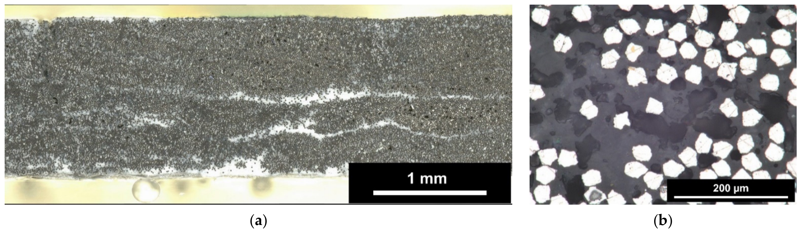
Representative polished cross-sections of the as-fabricated unidirectional panel are shown in Figure 1a. The low-magnification overview shows the overall laminate microstructure together with matrix-rich regions distributed through the cross-section (white regions). No obvious porosity is resolved at this magnification. In contrast, the higher-magnification image (Figure 1b) reveals the local composite microstructure, including the Inconel 601 fibers, the surrounding matrix, and black hollow features corresponding to microscale porosity. These observations qualitatively support the Archimedes-based porosity measurements and show the residual porosity morphology remained within the laminate after processing.
Taken together, the measured density and apparent porosity show that the present material system was consolidated into a rigid composite laminate with reasonably consistent bulk physical properties, while retaining a substantial level of accessible porosity in the as-fabricated condition. These physical characteristics provide important context for interpretation of the subsequent mechanical and thermo-oxidative results.

5.2. Mechanical Properties

5.2.1. Results of ASTM D6272-17e1 Testing (Four-Point Bending), [0]6 Unidirectional Laminate

The results of the ASTM D6272-17e1 four-point flexural tests for the unidirectional [0]6 laminates are summarized in Table 4. Each condition was evaluated using five specimens. In the as-fabricated condition, the laminates exhibited a mean flexural strength of 503.0 MPa, mean compressive-side and tensile-side flexural moduli of 80.4 GPa and 78.3 GPa, respectively, and a mean average strain at failure of 0.64%. The corresponding standard deviations were 63.4 MPa, 4.6 GPa, 4.9 GPa, and 0.05%, respectively.
After air aging at 427 °C for 336 h, the mean flexural strength was 528.6 MPa, while the mean compressive-side and tensile-side flexural moduli were 78.8 GPa and 77.4 GPa, respectively. The mean average strain at failure was 0.69%.
After air aging at 538 °C for 336 h, the corresponding values were 512.4 MPa for flexural strength, 80.7 GPa and 81.4 GPa for compressive-side and tensile-side flexural modulus, respectively, and 0.63% for average strain at failure.
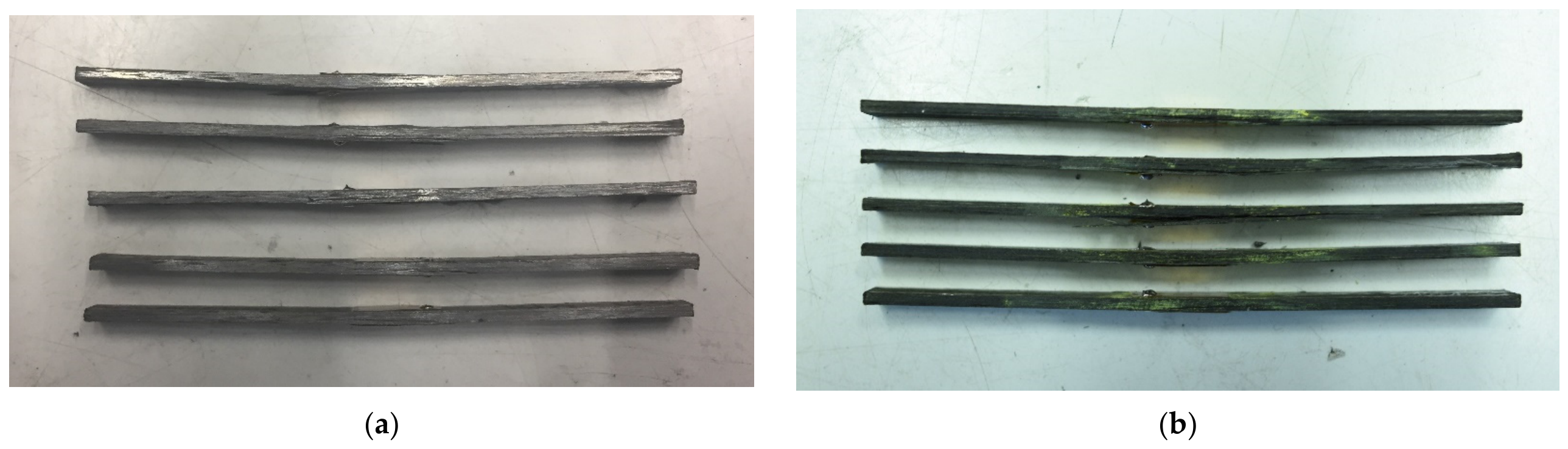
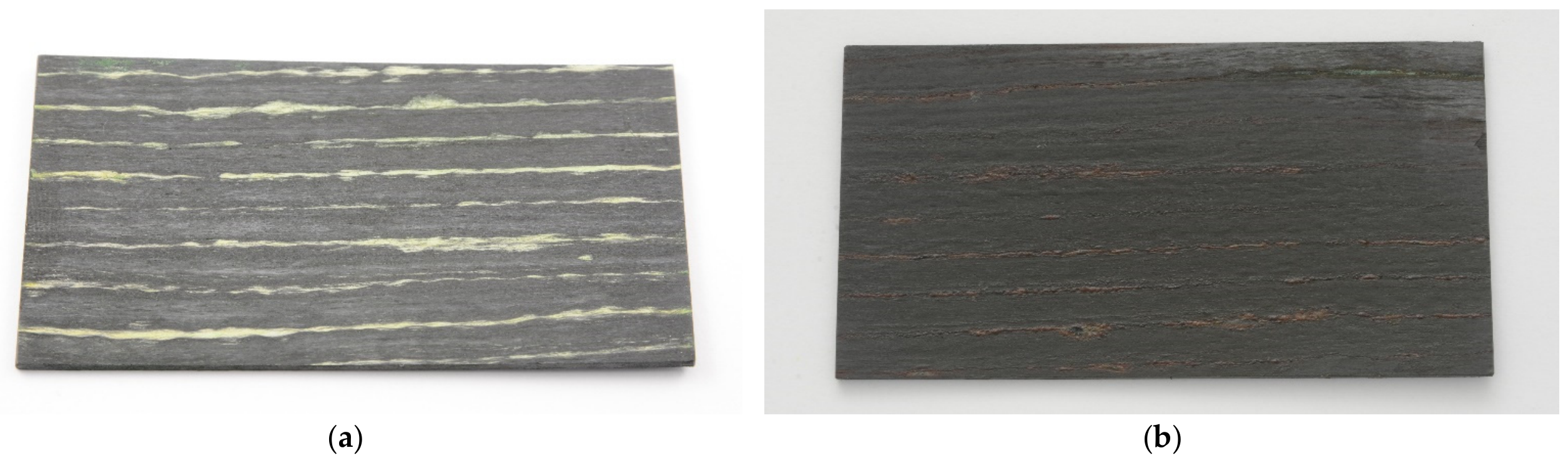
Across the three conditioning temperatures after 336 h, the measured flexural strength remained within the range of 503.0–528.6 MPa, the flexural modulus remained between 77.4 and 81.4 GPa, and the average strain at failure ranged from 0.63% to 0.69%. Post-test examination showed that failure was characterized primarily by shear and delamination under all conditions, indicating progressive damage development driven by initial matrix failure during bending rather than by a single abrupt fiber failure event. Representative post-test coupons are shown in Figure 2a,b. No differences in coupon failure modes were observed after aging at any conditioning temperature during flexural testing, despite the surface discoloration visible in Figure 2b. This is consistent with the lack of noticeable changes in properties, including strength and elastic constants, as measured by four-point flexural testing.

5.2.2. Results of ASTM C1359-18e1 Testing (Tension), [0]8 Unidirectional Laminate

The tensile properties of the unidirectional [0]8 laminates, measured in accordance with ASTM C1359-18e1, are summarized in Table 5. The laminates retained measurable tensile load-bearing capability from room temperature to 538 °C. The mean ultimate tensile strength was 365.0 MPa at RT, 327.9 MPa at 371 °C, 341.0 MPa at 427 °C and 346.7 MPa and 538 °C, respectively. The corresponding standard deviations were 20.7 MPa, 23.1 MPa, 15.9 MPa, and 11.0 MPa, yielding coefficients of variation of 5.7%, 7.0%, 4.7%, and 3.2%.
The mean tensile modulus showed a progressive decrease with increasing test temperature. The measured mean modulus was 90.3 GPa at RT, 78.6 GPa at 371 °C, 75.8 GPa at 427 °C, and 70.3 GPa at 538 °C. The corresponding standard deviations were 2.8 GPa, 1.1 GPa, 1.9 GPa, and 0.7 GPa, respectively, with coefficients of variation between 1.0% and 3.1%, indicating low scatter in stiffness measurements across all test temperatures.
Strain at failure was not reported for the RT and 371 °C conditions due to extensometer slip observed prior to peak load. For the temperatures at which valid strain data were obtained, the mean strain at failure was 0.48% at 427 °C and 0.58% at 538 °C, with standard deviations of 0.04% and 0.01%, respectively. The corresponding coefficients of variation were 8.33% and 1.72%.
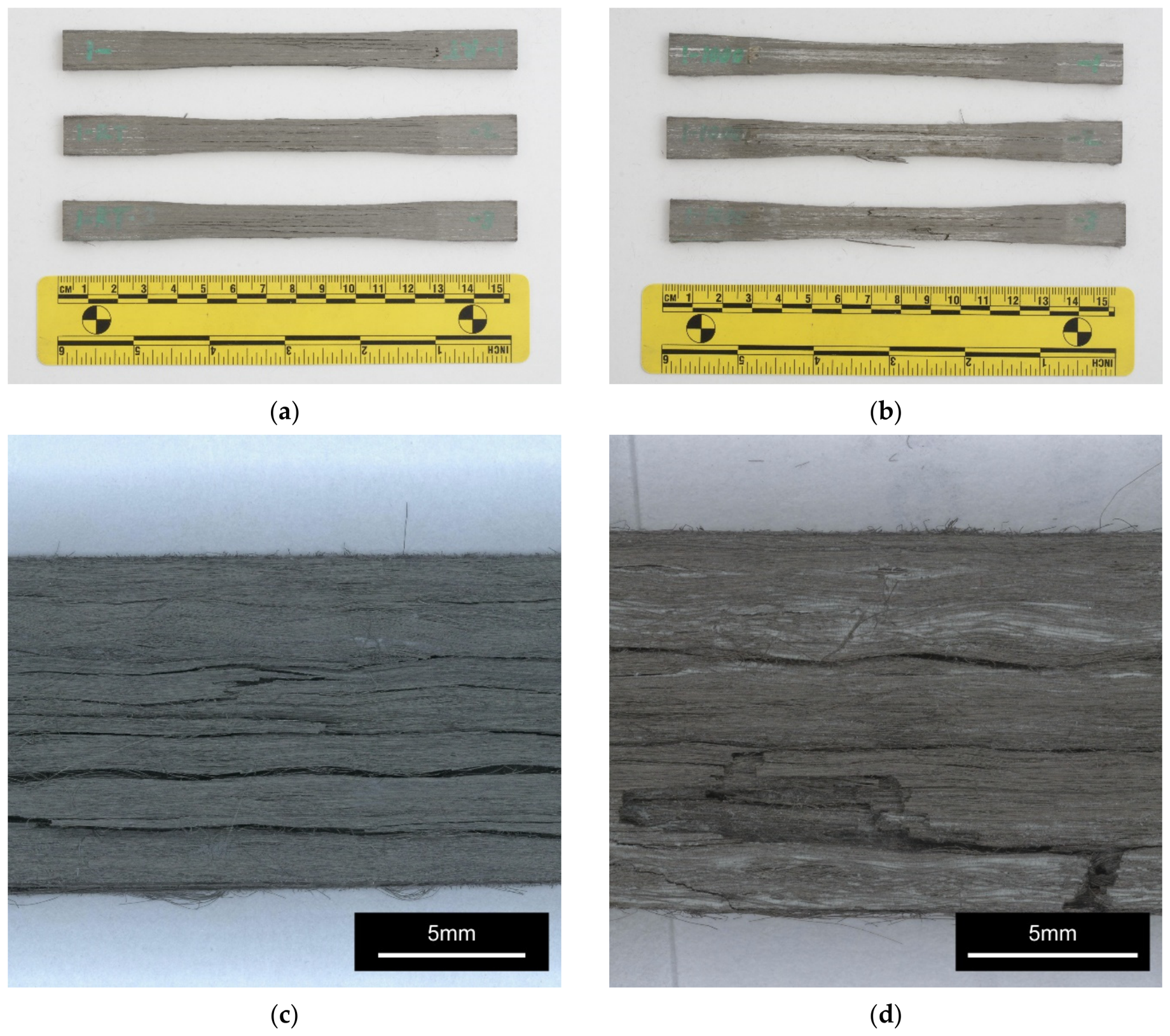
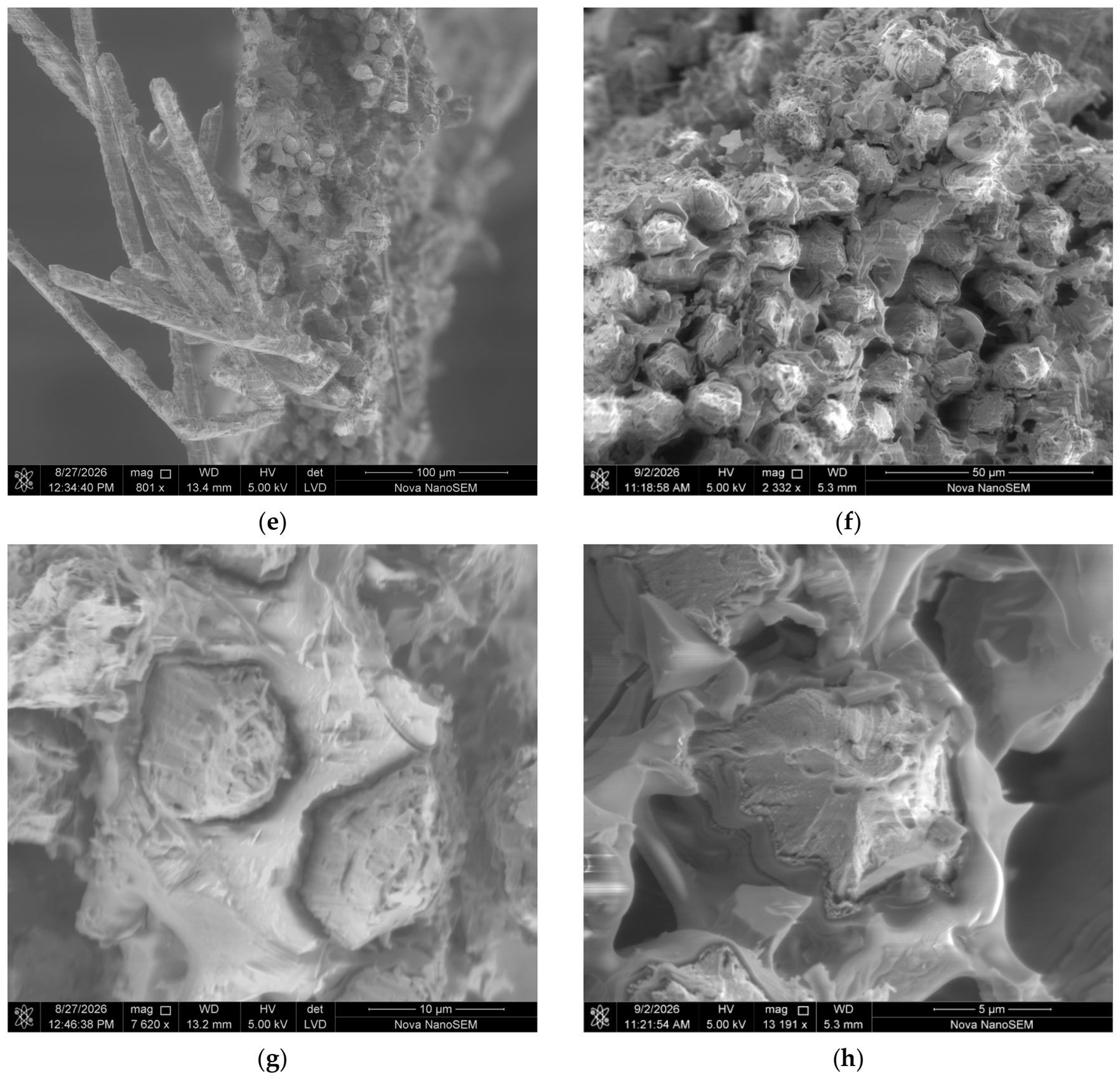
Overall, the unidirectional laminates exhibited tensile strengths in the range of 327.9–365.0 MPa and tensile moduli in the range of 70.3–90.3 GPa over the test temperatures investigated. Representative post-test coupons are shown in Figure 3a after testing at RT and Figure 3b after testing at 538 °C. The failed specimens remained intact after testing and exhibited failure mode in form of visible longitudinal splitting and distributed damage along the gauge section. No major changes in failure mode were observed among the samples tested at different temperatures. Close-up images of the specimen gage sections are presented in Figure 3c,d, revealing a splitting-type failure mode accompanied by localized tensile fracture of small sections. The fractured regions were subsequently examined by SEM. As shown in Figure 3e,f, the fracture surfaces exhibit no clear evidence of fiber debonding or pull-out at either test temperatures, indicating effective load transfer to the fiber up to fiber failure in tension. Higher-magnification images of representative individual filaments (Figure 3g,h) show fracture features characteristic of ductile overload, including dimple-like morphology associated with microvoid coalescence. These observations suggest that, as matrix cracks propagated toward the reinforcement, the fibers did not fail by shear-dominated fracture, but rather by tensile overload once the local stress in individual filaments exceeded their ultimate strength.
A first-order rule-of-mixtures (ROM) assessment was performed to evaluate the contribution of the metallic fibers to the composite modulus of the unidirectional tensile test coupons. All input data used for this assessment are summarized in Table 6. For this purpose, a nominal fiber volume fraction of 39 vol.% was assumed as a representative nominal value for the produced laminates. Together with the measured apparent porosity of 24.88 vol.%, this corresponds to remaining matrix fraction of 36.12 vol.%. The longitudinal elastic modulus was estimated using the following rule-of-mixtures expression:
E t = V f E f + V m E m ,
where
V m = 1 V f V p .
The exact elastic constants of Inconel 601 in fibrous form are not known to the authors. However, the elastic modulus is considered to be governed primarily by the chemical composition of the alloy and is generally less sensitive to product form, prior cold work, or heat-treatment history than strength. Accordingly, the tensile modulus of Inconel 601 was taken as 206.5 GPa at room temperature [27] and 175 GPa at 538 °C, the latter being obtained by linear interpolation between available data points [27]. A representative geopolymer matrix modulus of 18.5 GPa was used [33] and, in the absence of temperature-dependent data, was assumed to remain constant over the temperature range considered. On this basis, the predicted longitudinal modulus is 87.2 GPa at room temperature and 74.9 GPa at 538 °C. These values are in reasonable agreement with the measured laminate tensile moduli of 90.3 GPa at room temperature and 70.3 GPa at 538 °C, respectively, as summarized in Table 7. This indicates that the longitudinal tensile modulus is broadly consistent with the expected contribution of the metallic fibers and suggests that load transfer between matrix and fibers is effective.
A corresponding first-order strength estimate was made using the following rule-of-mixtures expression:
F t u = V f S f + V m S m ,
The tensile strength of the Inconel 601 reinforcement (Sf) was estimated using a baseline value of 1425 MPa at room temperature and 1164 MPa at 538 °C. The latter value was extrapolated from commercial product datasheets based on the strength debit between room temperature and 538 °C, using the maximum reported values for the end-drawn wire form [27], since the exact tensile properties of Inconel 601 fibers are not available in the literature and were not provided by the manufacturer. The authors consider this value to represent a conservative lower bound for the present analysis. Because the microfibers used in this study have an ultra-fine diameter of approximately 12 µm, their actual tensile strength would be expected to lie toward the high end of the achievable strength range for this alloy. This expectation is supported by mechanisms such as grain refinement associated with severe plastic deformation (since the fibers were supplied in end-drawn condition) as described by the Hall–Petch relationship [34,35], and by the reduction in critical flaw population in small material volumes, as described by weakest-link statistical theory [36]. Similar size- and strain-strengthening effects have also been reported for other metallic microfibers, for example in stainless steel systems reaching strengths above 2000 MPa [37]. A representative geopolymer matrix strength of 27.8 MPa was also used [33] and, in the absence of temperature-dependent data, was assumed to remain constant over the temperature range considered. Consequently, this ROM comparison serves as a first-order assessment intended to determine whether the composite longitudinal tensile strength is predominantly fiber- or matrix-derived, rather than as a rigorous quantification of reinforcement efficiency. On this basis, the analysis indicates that the composite tensile strength remains primarily fiber-dominated, while the matrix plays a secondary role related mainly to load transfer, structural constraint, and preservation of laminate integrity.
Using this approach, the predicted longitudinal tensile strength of the unidirectional laminates is 565.8 MPa at room temperature and 464.0 MPa at 538 °C. This assessment likewise indicates that the metallic fibers provide the dominant contribution to the longitudinal load-carrying capability of the material. A summary of the predicted and measured strength values is provided in Table 7.

5.2.3. Results of ASTM C1359-18e1 Testing (Tension), [0/90]2S Balanced Laminate

The tensile properties of the balanced [0/90]2S laminates, measured at room temperature in accordance with ASTM C1359-18e1, are summarized in Table 8. Two sets of specimens were tested from two panels lots. The reported values represent the average of n = 3 specimens for each set of panels. Results from panel lot ID#1 exhibited a mean ultimate tensile strength of 163.4 MPa, a mean tensile modulus of 46.9 GPa, and a mean strain at failure of 0.36%. The corresponding standard deviations were 9.9 MPa, 1.6 GPa, and 0.02%, respectively, yielding coefficients of variation of 6.1%, 3.4%, and 4.26%. Results from panel lot ID#2 exhibited a mean ultimate tensile strength of 174.2 MPa, a mean tensile modulus of 44.2 GPa, and a mean strain at failure of 0.46%. The corresponding standard deviations were 15.3 MPa, 1.7 GPa, and 0.03%, respectively, with coefficients of variation of 8.8%, 3.9%, and 6.83%.
Across the two series, the measured tensile strength ranged from 163.4 MPa to 174.2 MPa, while the tensile modulus ranged from 44.2 GPa to 46.9 GPa. The corresponding strain at failure ranged from 0.36% to 0.46%. The modulus values showed relatively low scatter in both series, whereas tensile strength and strain at failure exhibited somewhat greater specimen-to-specimen variability.
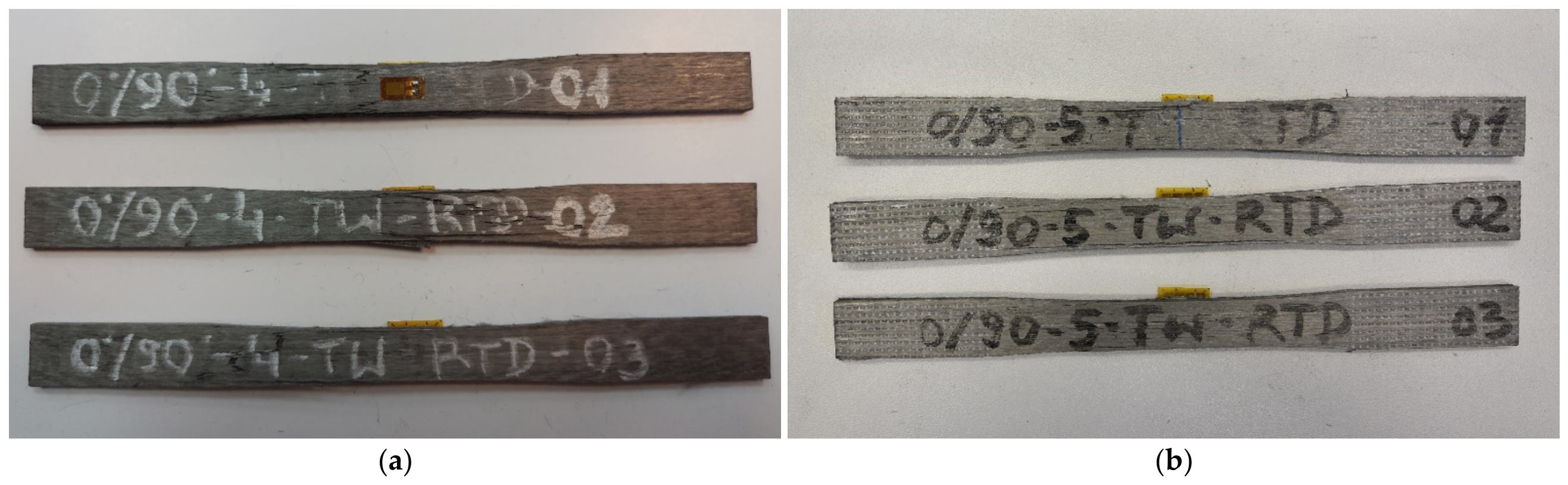
Representative post-test coupons are shown in Figure 4. The failed specimens remained largely intact after testing and exhibited visible longitudinal cracking mixed with tensile failure of 0° plies within the gauge section and outside of the gauge section.
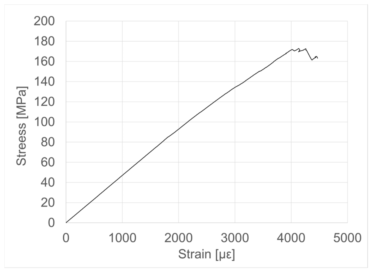
A representative stress–strain curve is shown in Figure 5. The curve was approximately linear up to a stress level near 170–180 MPa, corresponding to a strain of about 4000 µε, after which a slight load drop or plateau was observed prior to final failure. The curve therefore indicates a predominantly linear tensile behavior followed by a short nonlinear region immediately preceding fracture.

5.3. Oxidation Kinetics and Microstructural Evaluation After Thermo-Oxidative Exposure

Initial four-point flexural screening showed no measurable reduction in room-temperature flexural properties after air exposure at 538 °C for 336 h. Over the same exposure duration, the mass increase in the flexural specimens remained below 1%. Because exposure up of the material to temperatures of up to 538 °C for 336 h was mechanically inconsequential to its properties, subsequent thermo-oxidative evaluations were deliberately conducted at elevated temperatures of 649 °C, 760 °C, and 816 °C. These higher exposures were designed as accelerated tests to force measurable mass gains and to accelerate microstructural changes. The objective was to explore the degradation mechanisms and possible thermo-oxidative limits of the Inconel 601 reinforced geopolymer-derived aluminosilicate matrix composites.

5.3.1. Matrix-Agnostic Scale-Correction Factor Derivation

To evaluate the oxidation kinetics of the composite specimens, a matrix-agnostic scale-correction factor was implemented to isolate the chemical reactivity of the metallic phase from the geopolymer matrix, being inert to oxidation related mass gain. The specimen’s initial state is defined by its total geometric volume ( V 0 ), its initial bulk mass ( m 0 ), and a nominal Inconel 601 fiber volume fraction ( V f ) of 39% (0.39). Because the geopolymer matrix consists of fully oxidized species that cannot undergo further oxidation-related mass gain, any dynamic mass change is strictly assigned to the metallic reinforcement. The initial mass fraction of the reactive Inconel 601 ( f f ) was derived using the following geometric-mass relationship:
f f = m f m 0 = ρ f · V f · V 0 m 0 = V f · ρ f ρ 0 ,
where ρ f is the theoretical bulk density of Inconel 601 (8.11 g/cm3) [27] and ( ρ 0 ) is the measured initial bulk density of the composite specimen (4.05 g/cm3) ( ρ 0 = m 0 / V 0 ). This relationship yields a metallic mass fraction within the composite of ≈0.78). Consequently, the true, scale-corrected fractional mass gain of the reacting substrate ( X ) was calculated as:
X = M e x p e r i m e n t a l 100 · f f ,
where ( M e x p e r i m e n t a l ) is the raw mass change recorded from the experimental data expressed in percentage (%).

5.3.2. Evaluation of Oxidation Kinetics

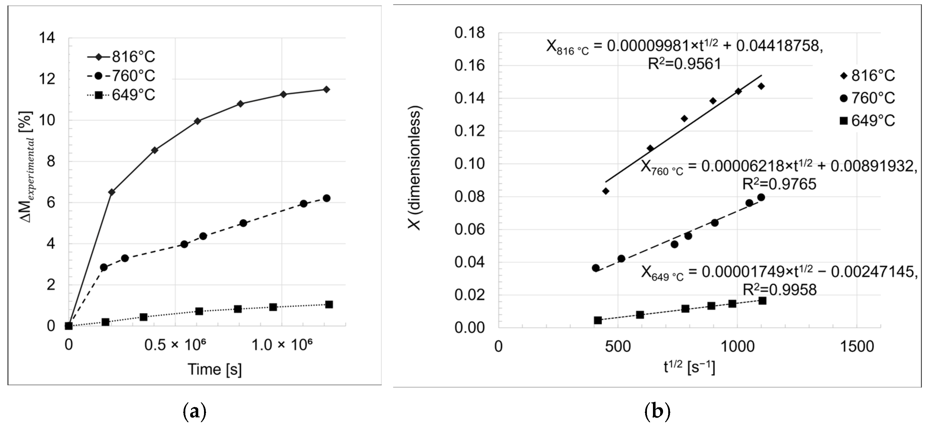
Non-corrected raw sample mass gain ( M e x p e r i m e n t a l ) as a function of exposure time ( t ) is presented in Figure 6a, while the scale-corrected fractional mass gain ( X ) is plotted against square root of time ( t 1 / 2 ) is plotted in Figure 6b. The evaluation of oxidation kinetics is expressed in terms of fractional mass change rather than absolute mass gain per surface area. This approach is adopted because the actively oxidizing component in this system is exclusively the fibrous reinforcement, which is exposed to a network of pores and exhibits a highly developed surface area compared to traditional bulk metallic materials. Furthermore, this form of data representation enables a comparison between the findings of this study and the oxidation kinetics data available for the same type of fiber (Inconel 601 12 µm in diameter) evaluated using a similar analytical methodology [38].
Under steady-state, diffusion-controlled conditions, the oxidation kinetics obey the classic parabolic rate law, linearized as:
X = k p 1 / 2 · t 1 / 2 ,
where t is the exposure time in seconds and k p is the parabolic rate constant ( s 1 ). Since the first data point was recorded after 48 h of exposure (~172,800 s), the initial transient oxidation stages are not captured in this analysis.
When the parabolic rate constant is calculated from a linear regression equation, Equation (6) is transformed into:
X = m · t 1 / 2 + C ,
where m represents the linear slope, while C is the linear intercept on the ordinate.
To maintain methodological consistency across the entire temperature range and to enable the subsequent calculation of the Arrhenius activation energy, a linear regression model representing the parabolic law was applied uniformly to all three temperature datasets. While deviations from this law occur above 649 °C, maintaining a uniform model provides dimensionally consistent input values for the Arrhenius activation energy calculation. Utilizing a standardized linear fit on the X versus t 1 / 2 plot yields a comparable “effective” parabolic rate constant ( k p ) for each condition. Furthermore, this standardized fit enables a direct comparison against established literature values that assume static parabolic kinetics available for the Inconel 601 12 µm in diameter fiber [38].
Scale-corrected mass gain as a function of the square root of exposure time ( t 1 / 2 ) is presented in Figure 6b. The data demonstrates clear temperature dependence and shifts in kinetic behavior across the investigated temperature range. At 649 °C, the linear regression model yielded high coefficient of determination (R2 = 0.9958), confirming a stable, classic parabolic regime with a calculated rate constant of k p = 3.06 × 10 10   s 1 . In contrast, the curve obtained at 760 °C showed an increased oxidation rate ( k p = 3.87 × 10 9   s 1 ) together with a slight upward deviation from the ideal linear regression line over time. Conversely, the 816 °C condition exhibited the highest initial mass gain rate ( k p = 9.96 × 10 9   s 1 ) but showed an inflection, with lower mass gain rates at late exposure stages.

5.3.3. Activation Energy Evaluation

To quantify the temperature dependence of the oxidized composite system and elucidate the underlying thermodynamic mechanisms, the effective parabolic rate constants ( k p ) determined at 649 °C, 760 °C, and 816 °C were modeled using the Arrhenius relationship [39]:
k p = A · e x p E a R · T ,
where A is the pre-exponential frequency factor (s−1), E a is the activation energy (J/mol), R is the universal gas constant (8.314 J/molK), and T is the absolute temperature in Kelvin (K). Equation (8) was linearized by plotting l n k p against the reciprocal absolute temperature (1/T) according to the expression:
l n k p = l n A E a R · 1 T ,
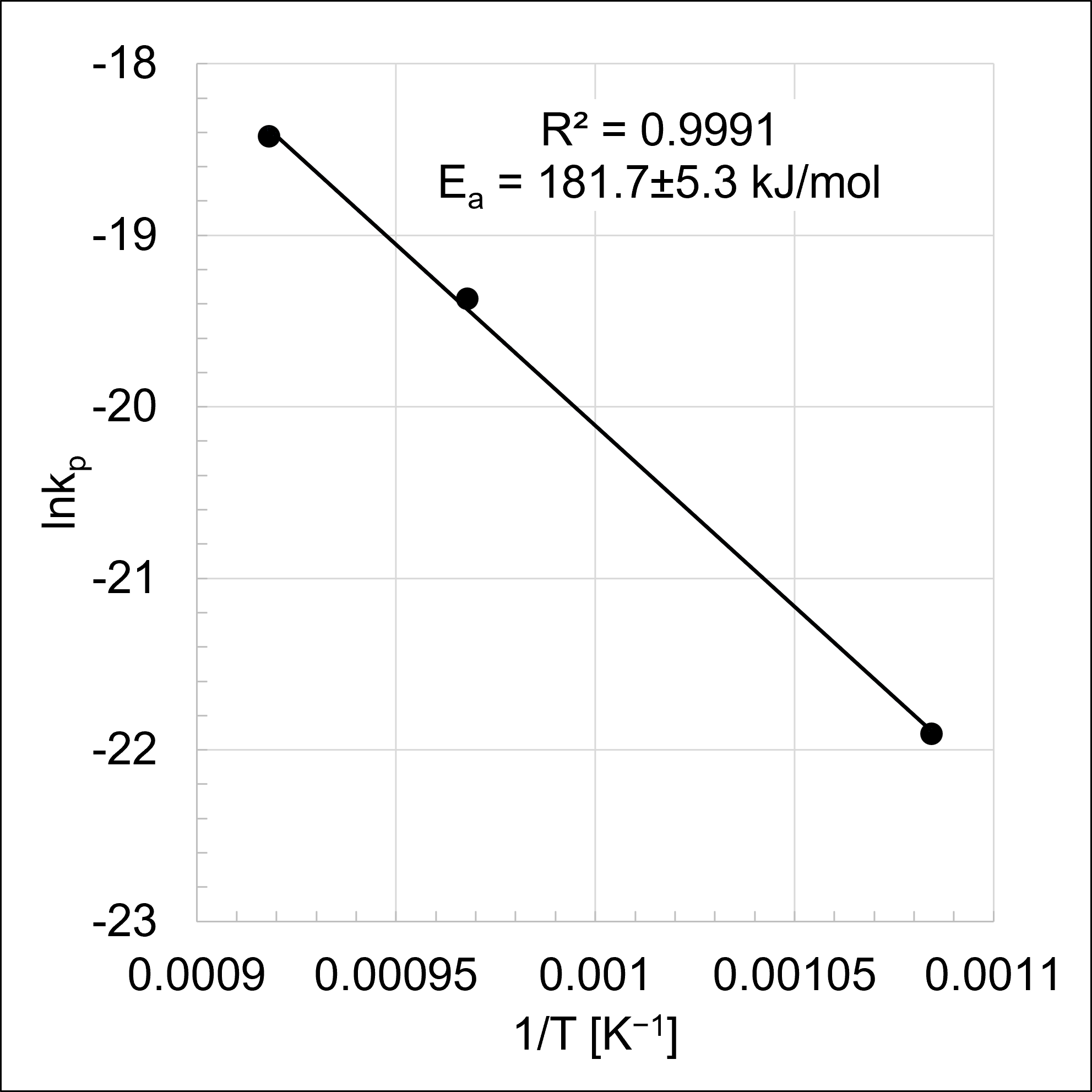
The resulting Arrhenius plot is shown in Figure 7 and demonstrated strong linear correlation (with a coefficient of determination of R2 = 0.9991), confirming that the macroscopically averaged oxidation kinetics across the investigated thermal range are governed by thermally activated, steady-state diffusion mechanisms. Through linear regression analysis using the least-squares method, the activation energy for the scale-corrected parabolic oxidation regime was determined to be Ea = 181.7 ± 5.3 kJ/mol. The uncertainty interval strictly represents the propagated standard error of the regression slope (SEm) extracted from the statistical analysis.

5.3.4. Microstructural Evaluation of Thermo-Oxidative Effects

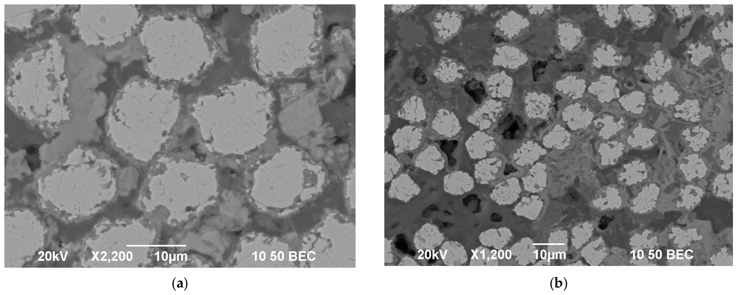
Cross-sectional SEM/EDS analysis revealed microstructural changes consistent with the oxidation trends identified in the preceding kinetic analysis. As shown in the comparative polished cross-sectional micrographs in Figure 8a and Figure 9a,b, the overall composite architecture remained recognizable even after 336 h of exposure at 816 °C; however, the extent of local fiber degradation increased with temperature.
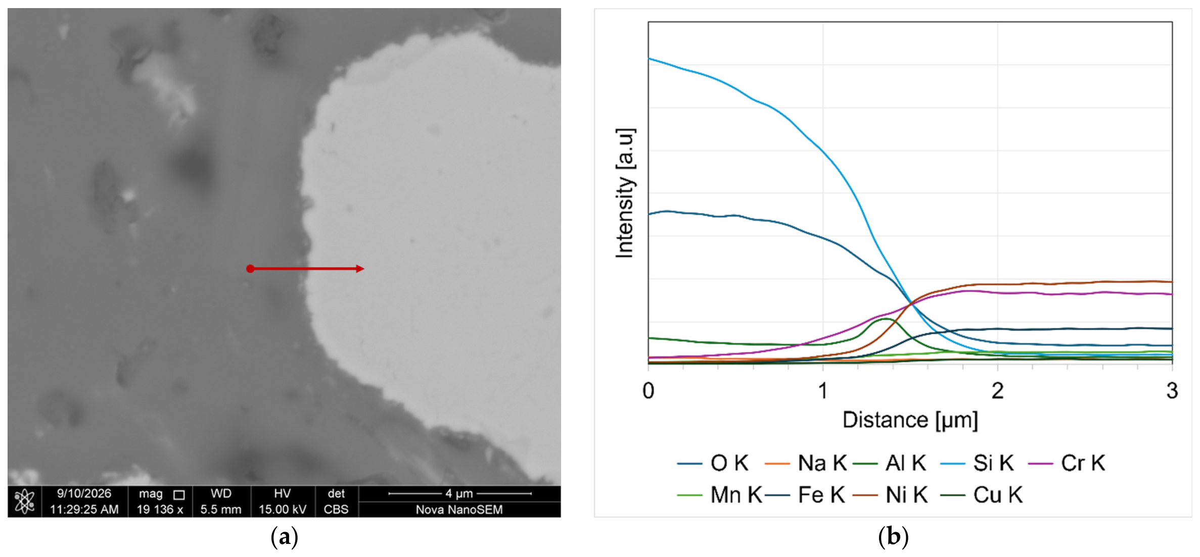
After 336 h of exposure at 649 °C, no apparent microstructural changes were observed by SEM at the fiber–matrix interface or in the surrounding regions, as shown in Figure 8a. In contrast, the corresponding EDS line-scan analysis in Figure 8b revealed the formation of a thin Al-rich layer at the fiber surface, accompanied by Cr diffusion into the adjacent matrix/interfacial region as shown in Figure 8b. The presence of this aluminum-rich interfacial film is consistent with the good fit of the parabolic model identified in the preceding kinetic analysis, suggesting that its growth is controlled by mass transport through the film. At the same time, the chromium signal increased progressively within the adjacent matrix surrounding the fiber, indicating the development of an elemental gradient extending outward from the interface into the matrix.
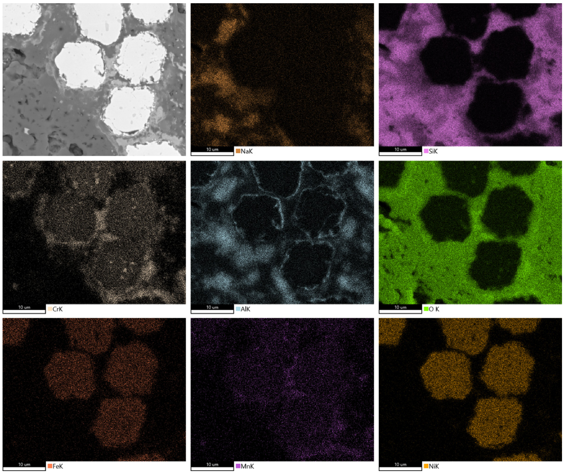
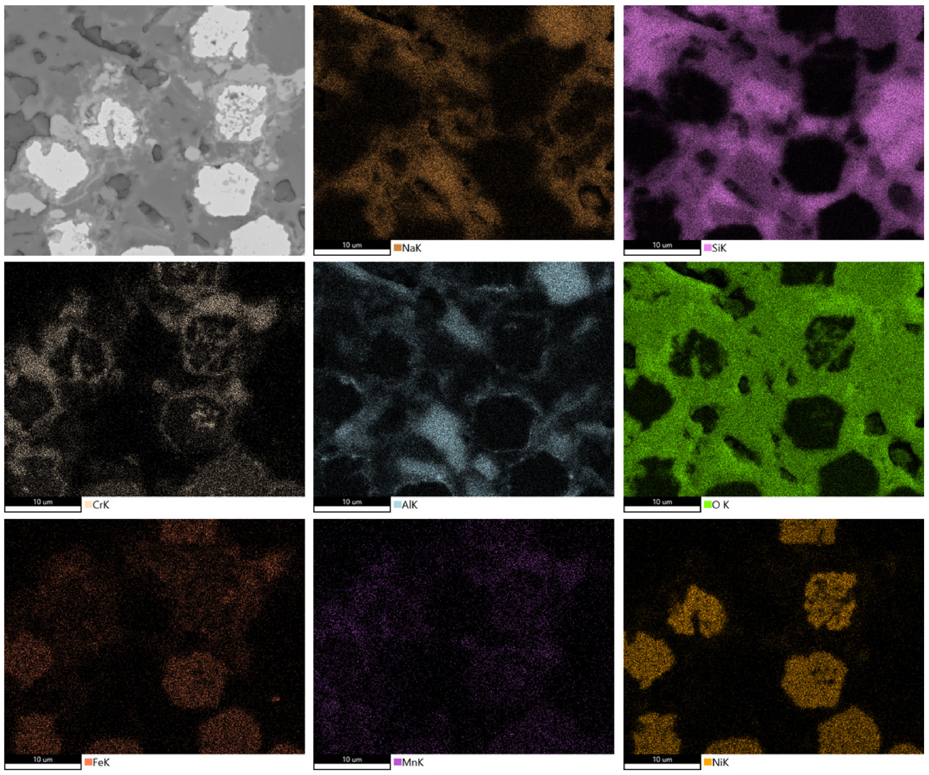
After 336 h of exposure at 760 °C, the Al-rich surface layer remained detectable, whereas the diffusion of elements from the Inconel 601 alloy into the adjacent matrix became more pronounced. The SEM cross-sectional micrograph and corresponding EDS elemental maps are presented in Figure 10. Although the fiber largely retained its original morphology, a new phase, several hundred nanometers thick and enriched in Cr, Mn, and O, formed together with localized fiber degradation manifested as small pits. Compared with the specimen exposed at 649 °C, outward diffusion of elements constituting the fiber was more pronounced, as indicated by increased Cr enrichment and the onset of Mn diffusion into the surrounding matrix in the region of the newly formed phase.
At 816 °C, degradation became substantially more severe. The SEM cross-sectional micrograph and corresponding EDS elemental maps in Figure 11, obtained from the specimen exposed for 336 h, reveal extensive oxidation-related alteration of the metallic reinforcement and the adjacent interfacial region. In contrast to the behavior observed at lower temperatures, the Al-rich surface layer was no longer detectable, and the cross-sectional microstructure showed visible attack extending into the fiber core, indicating that degradation was no longer limited to the fiber periphery. In addition, the elemental maps suggest outward diffusion of metallic species into the surrounding matrix, particularly Cr, Mn, and Fe. The lower Cr and Mn intensities detected within the fiber relative to the surrounding region further suggest depletion of these elements from the fiber and their accumulation in the adjacent interfacial area.
The macroscopic appearance of the specimen after exposure at 816 °C for 56 h and 336 h is presented in Figure 12. The surface showed general darkening accompanied by localized green discoloration, with both features becoming more pronounced with increasing exposure time. Nevertheless, the specimen remained macroscopically intact.
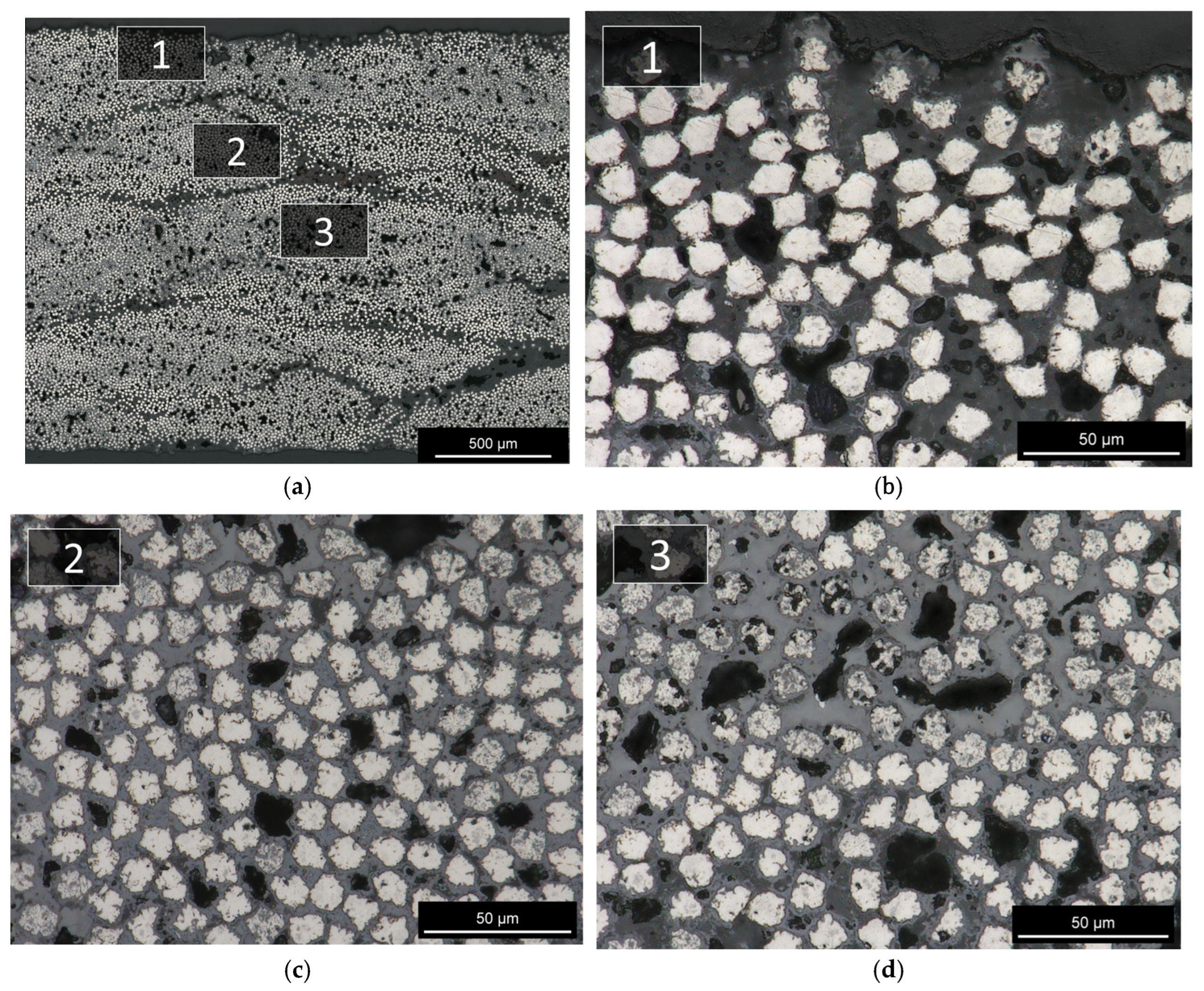
Additional polished cross-sectional micrographs of specimens exposed to air at 816 °C for 336 h are provided in Figure 13, illustrating the oxidation morphology of fibers in different regions of the sample. These images indicate that the oxidation-related attack was not limited to a narrow near-surface region, but occurred across multiple locations throughout the specimen thickness. The presence of degraded fibers through the cross section is consistent with oxygen ingress through internal pore pathways and supports the oxidation kinetics and porosity-assisted transport behavior discussed previously.
Taken together, the microstructural observations in Figure 8, Figure 9, Figure 10, Figure 11, Figure 12 and Figure 13 follow the same temperature-dependent trend identified in the preceding kinetic analysis. At 649 °C, the dominant features are the formation of an Al-rich interfacial film and the onset of Cr diffusion into the surrounding matrix. At 760 °C, the Al-rich layer is still detectable, while outward diffusion of Cr and Mn becomes more pronounced. At 816 °C, the Al-rich surface film is no longer observed, and the microstructure shows localized fiber attack together with more extensive diffusion of Cr and Mn into the matrix.

6. Discussion

The present results show that continuous-fiber laminates based on Inconel 601 reinforcement and a geopolymer-derived aluminosilicate matrix can be produced by a slurry impregnation/prepreg route followed by low-temperature consolidation and post-cure. The fabricated laminates exhibited measurable tensile strength at room temperature and up to 538 °C, and no measurable reduction in room-temperature flexural strength was observed after prolonged exposure in air at 538 °C under the conditions investigated. At the same time, the measured density, apparent porosity, tensile strength, and thermo-oxidative behavior indicate that both the material system and processing route remain under development and are not yet fully optimized. Additional work is required to evaluate effects of reduced porosity and improved matrix densification and the resulting effects on mechanical properties, and environmental durability.
The as-fabricated laminates exhibited a bulk density of 4.05 ± 0.08 g/cm3 and an apparent porosity of 24.88 ± 0.62%. The corresponding micrographs show microscale voids together with matrix-rich regions distributed through the laminate thickness. These results indicate that the present cure/consolidation condition produced rigid composite panels but did not eliminate accessible porosity. Within the scope of the present study, this porosity is interpreted primarily as a characteristic of the present processing state rather than as a definitive limitation of the material concept. Residual open porosity is considered to influence oxygen ingress during environmental exposure and to affect the mechanical properties of the composite; however, this effect was not directly investigated at this stage of the test program because doing so would have required a separate test campaign to produce panels with tailored porosity levels, which was not feasible at the time. Hence, a more detailed assessment of pore morphology, size distribution, and connectivity, as well as their relationship to oxidation kinetics and its impact on mechanical properties, is recognized as an important area for future work, but was beyond the scope of the present study.
Despite this porosity, the laminates exhibited measurable tensile properties in both unidirectional and balanced architectures. The [0]8 laminates retained tensile strengths in the range of approximately 328–365 MPa from room temperature to 538 °C, while the tensile modulus decreased from approximately 90 GPa at room temperature to 70 GPa at 538 °C, corresponding to a reduction of approximately 23%. A first-order rule-of-mixtures assessment showed that the predicted longitudinal modulus was in close agreement with the measured values, indicating that the elastic response of the unidirectional laminate is largely governed by the metallic fiber reinforcement and is consistent with effective load transfer between matrix and fibers. The observed reduction in modulus with increasing temperature is also consistent with the known temperature dependence of Inconel 601, whose elastic modulus decreases by approximately 18% between room temperature and 538 °C [27], although additional contribution due to drop of matrix modulus as a function of temperature cannot be excluded on the basis of the present data. By contrast, the corresponding strength-based rule-of-mixtures assessment is associated with greater uncertainty because the exact tensile strength of the Inconel 601 reinforcement in fibrous form is not known. Nevertheless, the measured and predicted tensile strengths remain of the same overall order of magnitude and support the interpretation that the longitudinal tensile properties are predominantly fiber-dominated, while the matrix contribution is secondary and related mainly to load transfer, structural constraint, and laminate integrity. This interpretation is also qualitatively supported by the higher flexural strengths measured for the same material system, which suggest that the uniaxial tensile coupons may have been more sensitive to premature splitting-related failure and therefore may not have fully reflected the intrinsic load-carrying capability of the fiber reinforcement. This interpretation is further supported by the fractographic observations. As shown by the SEM examination of the fracture surfaces, no clear evidence of extensive fiber debonding or pull-out was observed at either test temperature; instead, the fracture morphology was characterized by fiber failure consistent with tensile overload. At higher magnification, representative filaments exhibited dimple-like fracture features associated with microvoid coalescence, indicating a ductile failure mode of the metallic reinforcement. These observations are consistent with effective load transfer between the fiber and the matrix up to the final fiber failure, which likely occurred after matrix splitting-type cracking had initiated and progressed to a point where localized sample fragments saw stress concentration leading to the overstress of individual filaments.
It should also be noted that the metallic fibers used in the present study do not exhibit the typical circular cross-sectional morphology commonly associated with conventional composite reinforcements but instead display irregular hexagonal or multi-faceted cross sections at the micrometer scale as seen in Figure 1b. Such a morphology may promote local stress concentrations in the surrounding matrix and thereby contribute to the initiation of matrix microcracking and the subsequent development of splitting-type failure. The balanced [0/90]2S laminates exhibited lower room-temperature tensile properties than the unidirectional material, consistent with the reduced fraction of load-bearing 0° fibers relative to the unidirectional laminate.
To place the present results in context, the investigated material system was compared with oxide/oxide (Ox/Ox) CMCs as presented in Table 9, which represent a useful benchmark for temperature-resistant composite materials in the intermediate-temperature range, where high-performance organic polymer-based composites begin to lose capability and non-oxide CMCs may be less attractive from a cost standpoint. It is recognized that commercial Ox/Ox systems such as Nextel 720/alumina are designed for substantially higher-temperature service and offer superior long-term durability under those conditions. The comparison is therefore not intended to imply equivalence in overall temperature capability, but rather to assess whether the present material concept can achieve a comparable initial load-bearing capability within the more limited temperature window considered here.
For reference, a standard 12-ply 0/90 woven Nextel 720/alumina laminate typically exhibits an ultimate tensile strength of 163–179 MPa [41]. The present [0/90]2S laminate exhibited room-temperature ultimate tensile strengths of 163.4 MPa and 174.2 MPa. Although the specific tensile strength of the present laminate is lower because of its higher density than oxide/oxide CMCs, the close agreement in absolute tensile strength suggests that the proposed system may provide a similar initial load-bearing capability within the limited temperature range considered in this study.
The thermo-oxidative results provide an initial indication of the temperature range over which the present system may remain stable under the conditions examined. Four-point flexural screening after air exposure at 538 °C for 336 h did not indicate a measurable loss in room-temperature flexural strength, and the corresponding mass change remained below 1% over the same duration. Above 538 °C, however, oxidation kinetics accelerate and the governing mechanisms evolve as a function of temperature.
The temperature-dependent oxidation kinetic behavior correlates with microstructural changes within the composite. To maintain analytical consistency, parabolic fit was applied across all investigated temperatures. At 649 °C, this model yielded an excellent fit to the experimental mass-gain data, establishing an effective oxidation rate constant of k p = 3.06 × 10 10   s 1 , this being higher than the reported k p = 1.41 × 10 10   s 1 for neat fibers at 700 °C [38] and with lower activation energy (181.7 kJ/mol, against 330 kJ/mol [38]). Comparison of calculated oxidation rate constants from this work and reported literature data for neat fiber is shown in Table 10. Microstructural characterization at this temperature revealed the formation of an Al-rich interfacial film, accompanied by the early stages of Cr diffusion from the fibers outward into the surrounding matrix. This strong parabolic correlation and the presence of the Al-rich interfacial film are consistent with a diffusion-controlled mechanism, where the rate of oxygen ingress is limited by transport through a growing reaction layer. However, because the outward diffusion of Cr into the surrounding matrix does not clearly participate in the formation of a passivating film, prolonged thermal exposure poses a risk of material degradation, as the matrix starts to destabilize the system’s potential for subsequent chromia passivation. Hence, extended exposures beyond the timeframe of this study may trigger changes in fiber properties due to cumulative Cr depletion, as well as shifts in the long-term oxidation kinetics, both of which require quantification in future work.
At 760 °C, the oxidation rate constant increases to k p = 3.87 × 10 9   s 1 (which is also higher than the reported values for neat fibers, but within the similar order of magnitude [38]), while the coefficient of determination decreases to R 2 = 0.9765 . This indicates an onset of deviation from ideal parabolic behavior over the exposure period. Microstructural characterization shows that while the Al-rich interfacial film remains detectable, the outward diffusion of alloying elements from the fibers is more pronounced than at 649 °C. The fiber largely retains its morphology, but the increased diffusion of Cr and the onset of Mn migration lead to the formation of a localized, multi-element phase enriched in Cr, Mn, and O, accompanied by localized pitting. This behavior confirms that the matrix continues to alter the transport of reactive elements, preventing the development of a stable passivation layer in which Cr participates and results in an increased oxidation rate.
At 816 °C, the effective oxidation rate constant increases to k p = 9.96 × 10 9   s 1 remains higher than that reported for neat fibers [38]. Microstructural characterization shows a further change in the oxidation mechanism, as the Al-rich interfacial film is no longer detectable. This observation is consistent with an inflection observed in the k p   v s   t 1 / 2 plot, as after approximately 790 s 1 / 2 the mass gain rate decreases, which may be explained by the loss of diffusion controlling function of the Al-rich film. In addition, localized oxidation attack extending into the fiber core is observed, indicating that the fiber degradation is no longer confined to the fiber periphery. Elemental mapping reveals a more extensive outward diffusion of Cr and Mn into the adjacent matrix, now accompanied by the migration of Fe. Furthermore, lower relative intensities of Cr and Mn within the fiber core suggest a depletion of these elements from the metallic reinforcement and their accumulation in the interfacial region. Cross-sectional micrographs across multiple locations demonstrate that this oxidation morphology is present throughout the specimen thickness rather than being limited to the near-surface region. This behavior is consistent with internal oxygen transport facilitated by the pore network of the laminate. However, qualitatively, the extent of degradation is not identical across all individual filaments, suggesting that local variations in porosity may impact the oxidation kinetics.
Overall, the present results indicate that the Inconel 601/geopolymer-derived composite may be of interest for intermediate-temperature applications, rather than as a substitute for high-temperature CMC systems. The current dataset suggests that the material can provide measurable laminate-scale tensile properties while being produced from commercially available metallic reinforcement and a geopolymer-derived matrix. However, the current porosity level, and oxidation behavior at higher temperatures indicate that further development is required, particularly with respect to porosity reduction and processing optimization. Future efforts should focus on long-term assessments of fatigue, creep, and environmental durability, alongside potential matrix compositional tailoring intended to stabilize and improve the oxidation resistance of the fibers. Such investigations are critical when considering the potential to extend the operational envelope toward higher temperatures, and as a function of both time and temperature, thereby establishing practical limits for the material’s application.
Thermal expansion mismatch between the metallic reinforcement and the geopolymer-derived matrix is also expected to be an important factor governing residual stress development, interfacial stability, and long-term durability; however, rigorous assessment of this material system design aspect requires additional characterization of matrix-specific data that were beyond the scope of the present study.

7. Conclusions

The main findings of the present study can be summarized as follows:
  • Continuous-fiber laminates based on Inconel 601 reinforcement and a geopolymer-derived aluminosilicate matrix were produced by a slurry-impregnation/prepreg route followed by low-temperature consolidation and post-curing. The as-fabricated laminates exhibited a bulk density of 4.05 ± 0.08 g/cm3 and an apparent porosity of 24.88 ± 0.62%, indicating that the present processing condition produced rigid composite panels, but with open porosity.
  • The laminates exhibited measurable tensile properties in both unidirectional and balanced architectures. The [0]8 laminates retained tensile strengths in the range of approximately 327.9–365.0 MPa from room temperature to 538 °C, while the balanced [0/90]2S laminates exhibited lower room-temperature tensile properties than the unidirectional material, consistent with the reduced fraction of load-bearing 0° fibers.
  • The first-order ROM assessment showed close agreement between the predicted and measured longitudinal tensile modulus, indicating that the elastic response is primarily governed by the metallic fibers. The strength-based ROM comparison was subject to greater uncertainty because the exact tensile properties of the Inconel 601 fibers are not known. Nevertheless, the measured and predicted strengths remain of the same order of magnitude and support the conclusion that the fibers provide the dominant contribution to the composite tensile strength.
  • The room-temperature tensile strength of the balanced [0/90]2S laminate (163.4 MPa and 174.2 MPa for the two tested series) was of similar magnitude to values reported in the literature for a 12-ply 0/90 woven Nextel 720/alumina oxide/oxide CMC reference (163–179 MPa). This comparison is not intended to imply equivalence between the two systems, which differ substantially in constituent materials, architecture, density, processing maturity, and temperature capability, but rather to indicate that the present material system can achieve a comparable initial load-bearing capability within the considered intermediate-temperature range.
  • Thermo-oxidative testing showed no clear reduction, in room-temperature flexural properties after air exposure at 538 °C for 336 h, whereas higher-temperature exposure produced increasingly pronounced oxidation of the Inconel 601 fibers. The oxidation rate was temperature dependent: at 649 °C the mass-gain behavior followed parabolic law, consistent with the diffusion-controlled growth of a thin Al-rich interfacial film; at 760 °C the oxidation rate increased and, with the onset of deviation from ideal parabolic behavior, connected with diffusion of alloying elements and formation of a localized Cr-Mn-O-rich phase; and at 816 °C the highest initial mass gain was followed by a reduced late-stage rate, loss of the Al-rich surface film, and substantially more severe localized fiber attack extending into the fibers interior.
  • Comparison with literature data for neat Inconel 601 fiber indicates that the composite exhibits higher effective oxidation rate constants and lower activation energy in the studied composite form, demonstrating that the geopolymer-derived aluminosilicate matrix negatively affects oxidation resistance relative to the bare fiber.
  • Overall, the present results indicate that the Inconel 601/geopolymer-derived composite should be regarded as a potential material system for further maturation and development for intermediate-temperature applications. Further work should focus on optimizing processing, as this is expected to strongly influence the morphology, size distribution, connectivity and level of the open porosity. In turn, these porosity characteristics are likely to affect oxygen ingress, oxidation-related damage, fiber–matrix interfacial degradation, and mechanical property retention. Additional work is also needed to assess fatigue, creep, and environmental durability in order to define the practical application limits of the material. Future work should also address thermal property characterization, including thermal expansion behavior, thermal conductivity, thermal diffusivity, and thermal cycling resistance, with particular attention to the role of fiber–matrix thermal expansion mismatch in residual stress development and long-term durability.

Author Contributions

Conceptualization, M.J.; methodology, M.J. and A.J.; formal analysis, M.J.; investigation, M.J., A.J. and M.B.; resources, M.J. and M.B.; data curation, M.J., A.J. and M.B.; writing—original draft preparation, M.B.; writing—review and editing, M.J.; visualization, M.J.; supervision, M.J.; project administration, M.J.; funding acquisition, M.J. All authors have read and agreed to the published version of the manuscript.

Funding

This research was co-funded by the European Union within the European Regional Development Fund under Smart Growth Operational Programme 2014-2020–Grant Agreement No. POIR.01.01.01-00-0778/19 “Development of a new heat-resistant composite material for use in aircraft engine components”.

Data Availability Statement

The datasets presented in this article are not readily available as they are proprietary and part of an ongoing development program. Requests to access the datasets should be directed to Michal Jasiczek.

Acknowledgments

The authors acknowledge the technical support and laboratory services provided by the Łukasiewicz Research Network-Institute of Aviation (Warsaw, Poland) and Metcut Research Inc. (Carillon, OH, USA). The authors also gratefully acknowledge Bekaert (Zwevegem, Belgium) for supplying the materials used in this study.

Conflicts of Interest

Author Michal Jasiczek and Marcelina Bobrowska were employed by the company GE Aerospace. The remaining authors declare that the research was conducted in the absence of any commercial or financial relationships that could be construed as a potential conflict of interest.

Abbreviations

The following abbreviations are used in this manuscript:
BSAS/BASBarium strontium aluminosilicate/barium aluminosilicate
CASCalcium aluminosilicate
CMCCeramic-matrix composite
SiC/SiCSilicon carbide/silicon carbide composite system
CVIChemical vapor infiltration
RMIReactive melt infiltration
MIMelt infiltration
PIPPolymer infiltration and pyrolysis
SuFlexural strength
EftFlexural modulus in tension
EfcFlexural modulus in compression
εftStrain at failure in tension
εfcStrain at failure in compression
EtTensile modulus
Ftutensile strength
εfstrain at failure
RTRoom temperature
[0]8Unidirectional laminate layup with eight 0° plies
[0/90]2SBalanced cross-ply laminate layup with symmetric stacking sequence
CoVCoefficient of Variation
ROMRule-of-mixtures
VfFiber volume fraction
VmMatrix volume fraction
VpVoid volume fraction
EfFiber modulus
EmMatrix modulus
SfFiber tensile strength
SmMatrix tensile strength
ffFiber mass fraction in composite
mfFiber mass
m0Initial composite mass
ρfFiber density
ρ0Composite bulk density
XScale-corrected fractional mass gain
∆MRaw mass change
kpParabolic rate constant
tExposure time

References

  1. Davidovits, J. Geopolymers: Inorganic polymeric new materials. J. Therm. Anal. 1991, 37, 1633–1656. [Google Scholar]
  2. Lyon, R.E.; Balaguru, P.N.; Foden, A.; Sorathia, U.; Davidovits, J.; Davidovics, M. Fire-resistant aluminosilicate composites. Fire Mater. 1997, 21, 67–73. [Google Scholar] [CrossRef]
  3. Lahoti, M.; Wong, K.H.; Yang, E.-H.; Tan, K.H. Effects of Si/Al molar ratio on strength endurance and volume stability of metakaolin geopolymers subject to elevated temperature. Ceram. Int. 2018, 44, 5726–5734. [Google Scholar] [CrossRef] [Scilit]
  4. Duxson, P.; Fernández-Jiménez, A.; Provis, J.L.; Lukey, G.C.; Palomo, A.; van Deventer, J.S.J. Geopolymer technology: The current state of the art. J. Mater. Sci. 2007, 42, 2917–2933. [Google Scholar] [CrossRef] [Scilit]
  5. He, P.; Jia, D.; Lin, T.; Wang, M.; Zhou, Y. Effects of high-temperature heat treatment on the mechanical properties of unidirectional carbon fiber reinforced geopolymer composites. Ceram. Int. 2010, 36, 1447–1453. [Google Scholar] [CrossRef] [Scilit]
  6. Papakonstantinou, C.G.; Balaguru, P.N.; Lyon, R.E. Comparative study of high temperature composites. Compos. Part B Eng. 2001, 32, 637–649. [Google Scholar] [CrossRef] [Scilit]
  7. Lin, T.; Jia, D.; Wang, M.; He, P.; Liang, D. Effects of fibre content on mechanical properties and fracture behaviour of short carbon fibre reinforced geopolymer matrix composites. Bull. Mater. Sci. 2009, 32, 77–81. [Google Scholar] [CrossRef] [Scilit]
  8. Aziz, I.H.; Abdullah, M.M.A.B.; Yong, H.C.; Ming, L.Y.; Hussin, K.; Azimi, E.A. A review on mechanical properties of geopolymer composites for high temperature application. Key Eng. Mater. 2015, 660, 34–38. [Google Scholar] [CrossRef] [Scilit]
  9. Bansal, N.P. Effects of High-Temperature Annealing in Air on Hi-Nicalon Fiber-Reinforced Celsian Matrix Composites; NASA/TM—2008-215221; National Aeronautics and Space Administration, Glenn Research Center: Cleveland, OH, USA, 2008.
  10. Tredway, W.K.; Prewo, K.M. Carbon Fiber Reinforced Glass Matrix Composites for Structural Space Based Applications; Final Report R89-917704-1; United Technologies Research Center: East Hartford, CT, USA, 1989. [Google Scholar]
  11. Butkus, L.M.; Holmes, J.W.; Nicholas, T. Thermomechanical Fatigue Behavior of a Silicon Carbide Fiber-Reinforced Calcium Aluminosilicate Composite. J. Am. Ceram. Soc. 1993, 76, 2817–2825. [Google Scholar] [CrossRef] [Scilit]
  12. Bansal, N.P. CVD SiC fiber-reinforced barium aluminosilicate glass–ceramic matrix composites. Mater. Sci. Eng. A 1996, 220, 129–139. [Google Scholar] [CrossRef] [Scilit]
  13. Zhang, G.; Li, Y.; Zheng, S.; Wang, J.; Sglavo, V.M.; Xie, S. High performance SiC fiber-reinforced celsian matrix composites with BN/C/SiNx/C interface. J. Eur. Ceram. Soc. 2024, 44, 4482–4492. [Google Scholar] [CrossRef] [Scilit]
  14. Saroj, V.K.; Devgan, N.R.; Rajotia, M.; Panda, S. Recent Advancements in Glass Matrix Composites: A Comprehensive Review of Fabrication, Properties, and Applications. J. Am. Ceram. Soc. 2026, 109, e71011. [Google Scholar] [CrossRef] [Scilit]
  15. GE Aerospace. Ceramic Matrix Composite Technology. Available online: https://www.geaerospace.com/ (accessed on 28 May 2026).
  16. Yuan, J.; Yu, Y.; Ren, Q.; Yang, F.; Nie, H.; Huang, Z.; Li, Y. SiCf/SiC composites for nuclear safety applications: A review. Ceram. Int. 2026, 52, 16627. [Google Scholar] [CrossRef] [Scilit]
  17. Liu, R.; Wang, F.; Zhang, J.; Wan, F.; Wang, Y. Effects of CVI SiC amount and deposition rates on properties of SiCf/SiC composites fabricated by hybrid chemical vapor infiltration (CVI) and precursor infiltration and pyrolysis (PIP) routes. Ceram. Int. 2021, 47, 26971–26977. [Google Scholar] [CrossRef] [Scilit]
  18. Lamon, J. Chemical vapor infiltrated SiC/SiC composites (CVI SiC/SiC). In Handbook of Ceramic Composites; Bansal, N.P., Ed.; Springer: Boston, MA, USA, 2005; pp. 55–76. [Google Scholar]
  19. Süß, F.; Schneider, T.; Friess, M.; Koch, D. Combination of PIP and LSI processes for SiC/SiC ceramic matrix composites. Open Ceram. 2021, 5, 100056. [Google Scholar] [CrossRef] [Scilit]
  20. Katnic, S.P.; Latheef, M.A.A.; Sharp, K.; Martinez, M.; Singh, M. Addressing processing limitations in SiC-based ceramic composites: A review of hybrid approaches and perspectives. Ceram. Int. 2025, 51, 63501–63518. [Google Scholar] [CrossRef] [Scilit]
  21. Silverstein, R.; Zok, F.; Levi, C. Vapor-mediated melt infiltration for synthesizing SiC composite matrices. J. Am. Ceram. Soc. 2021, 104, 3833–3844. [Google Scholar] [CrossRef] [Scilit]
  22. Bhatt, R.; Lang, J.; Smith, C. Processing and properties of 3D woven SiC/SiC composites with hybrid matrix. J. Eur. Ceram. Soc. 2024, 44, 116739. [Google Scholar] [CrossRef] [Scilit]
  23. Ramachandran, K.; Bear, J.C.; Jayaseelan, D.D. Oxide-based ceramic matrix composites for high-temperature environments: A review. Adv. Eng. Mater. 2025, 27, 2402000. [Google Scholar] [CrossRef] [Scilit]
  24. Simon, R.A. Progress in processing and performance of porous-matrix oxide/oxide composites. Int. J. Appl. Ceram. Technol. 2005, 2, 141–149. [Google Scholar] [CrossRef] [Scilit]
  25. Karadimas, G.; Salonitis, K. Ceramic matrix composites for aero engine applications—A review. Appl. Sci. 2023, 13, 3017. [Google Scholar] [CrossRef] [Scilit]
  26. Scholz, H.; Vetter, J.; Herborn, R.; Ruedinger, A. Oxide ceramic fibers via dry spinning process—From lab to fab. Int. J. Appl. Ceram. Technol. 2020, 17, 1636–1645. [Google Scholar] [CrossRef] [Scilit]
  27. Special Metals Corporation. INCONEL Alloy 601; Special Metals Corporation: New Hartford, NY, USA, 2005; Available online: https://www.specialmetals.com/documents/technical-bulletins/inconel/inconel-alloy-601.pdf (accessed on 28 May 2026).
  28. Austral Wright Metals. Inconel Alloy 601 N06601. Available online: https://www.australwright.com.au/technical-data/alloys/high-performance-alloys/n06601-inconel-alloy-601/ (accessed on 28 May 2026).
  29. ASTM C20-00; Standard Test Methods for Apparent Porosity, Water Absorption, Apparent Specific Gravity, and Bulk Density of Burned Refractory Brick and Shapes by Boiling Water. ASTM International: West Conshohocken, PA, USA, 2000.
  30. Standard’s ISO/IEC 17025:2017; General Requirements for the Competence of Testing and Calibration Laboratories. International Organization for Standardization: Geneva, Switzerland, 2017.
  31. ASTM D6276-17e1; Standard Test Method for Flexural Properties of Unreinforced and Reinforced Plastics and Electrical Insulating Materials by Four-Point Bending. ASTM International: West Conshohocken, PA, USA, 2017.
  32. ASTM C1359-18e1; Standard Test Method for Monotonic Tensile Strength Testing of Continuous Fiber-Reinforced Advanced Ceramics with Solid Rectangular Cross Section Test Specimens at Elevated Temperatures. ASTM International: West Conshohocken, PA, USA, 2018.
  33. Samal, S.; Blanco, I. An Application Review of Fiber-Reinforced Geopolymer Composite. Fibers 2021, 9, 23. [Google Scholar] [CrossRef] [Scilit]
  34. Hall, E. The deformation and ageing of mild steel: III discussion of results. Proc. Phys. Soc. B 1951, 64, 747–752. [Google Scholar] [CrossRef] [Scilit]
  35. Petch, N.J. The orientation relationships between cementite and α-iron. Acta Crystallogr. 1953, 6, 96. [Google Scholar] [CrossRef] [Scilit]
  36. Carpinteri, A.; Puzzi, S. Size effect upon grained materials tensile strength. Theor. Appl. Fract. Mech. 2006, 45, 126–135. [Google Scholar] [CrossRef] [Scilit]
  37. De Bondt, S.; Decrop, J. Bundle Drawn Stainless Steel Fibers. International Patent Application WO 2003/010353 A1, 6 February 2003. [Google Scholar]
  38. Salmon, C.; Tiberghien, D.; Molins, R.; Colin, C.; Delannay, F. Oxidation behaviour in air of thin alloy 601 fibres. Mater. High Temp. 2000, 17, 271–278. [Google Scholar] [CrossRef]
  39. Birks, N.; Meier, G.H.; Pettit, F.S. Introduction to the High-Temperature Oxidation of Metals, 2nd ed.; Cambridge University Press: Cambridge, UK, 2006. [Google Scholar]
  40. Pritzkow, W.; Nöth, A.; Rüdinger, A. Oxide Ceramic Matrix Composites—Manufacturing, Machining, Properties and Industrial Applications. Ceram. Appl. 2015, 3, 48–53. [Google Scholar]
  41. Di Salvo, D.T.; Sackett, E.E.; Johnston, R.E.; Evans, W.J. Mechanical characterization of a fibre reinforced oxide/oxide ceramic matrix composite. J. Eur. Ceram. Soc. 2015, 35, 4513–4520. [Google Scholar] [CrossRef] [Scilit]
  42. Eber, C.A. Effect of Temperature and Steam Environment on Fatigue Behaviour of an Oxide-Oxide Continuous Fiber Ceramic Composite. Master’s Thesis, Air Force Institute of Technology, Wright-Patterson Air Force Base, Dayton, OH, USA, 2005. [Google Scholar]
Figure 1. Representative polished cross-sectional micrographs of the as-fabricated Inconel 601-reinforced geopolymer-derived aluminosilicate composite laminate: (a) low-magnification overview showing laminate-scale heterogeneity, including matrix-rich regions, with no clearly resolved pores at this magnification; and (b) higher-magnification view showing the metallic fibers, the surrounding geopolymer-derived matrix (gray contrast), and black void features corresponding to microscale porosity.
Jcs 10 00501 g001
Figure 2. Post-test coupons, ASTM D6272-17e1: (a) as-fabricated; (b) conditioned at 538 °C for 336 h in air.
Jcs 10 00501 g002
Figure 3. Post-test coupons after ASTM C1359-18e1 tensile testing: (a) tested at room temperature (RT); (b) tested at 538 °C; (c) close-up optical image of the gage section after testing at RT; (d) close-up optical image of the gage section after testing at 538 °C; (e,g) fractographic images of the tensile failure region for the specimen tested at RT; and (f,h) fractographic images of the tensile failure region for the specimen tested at 538 °C.
Jcs 10 00501 g003aJcs 10 00501 g003b
Figure 4. [0/90]2S post-test ASTM C1359-18e1 coupons tested at RT: (a) from panel ID #1, (b) from panel ID #2.
Jcs 10 00501 g004
Figure 5. Stress vs. Strain graph of [0/90]2S sample from panel series #ID2.
Jcs 10 00501 g005
Figure 6. Oxidation kinetic profiles of the composite specimens at elevated temperatures: (a) raw experimental mass gain percentage as a function of total exposure time, and (b) linearized kinetic plots of scale-corrected fractional mass gain ( X ) as a function of the square root of time ( t 1 2 ). The solid and dashed lines in (b) represent the global linear regression fits used to evaluate the effective parabolic rate constants ( k p ).
Jcs 10 00501 g006
Figure 7. Plot of the effective parabolic rate constants (lnkp) as a function of the reciprocal absolute temperature (1/T) for the Inconel 601 reinforced geopolymer composites. The solid line represents the linear regression fit used to determine the activation energy (Ea = 181.7 ± 5.3 kJ/mol), with the uncertainty interval representing the standard error of the regression slope.
Jcs 10 00501 g007
Figure 8. (a) Close-up SEM cross-sectional micrograph using Backscatter SEM imaging and (b) corresponding EDS line scan from the location marked with red arrow on (a) of the fiber–matrix interface after exposure to 649 °C for 336 h.
Jcs 10 00501 g008
Figure 9. Polished cross-sectional SEM micrographs of specimens exposed to air for 336 h: (a) 760 °C and (b) 816 °C, showing the increased severity of fiber oxidation and degradation morphology at the higher exposure temperature.
Jcs 10 00501 g009
Figure 10. SEM cross-sectional micrograph and corresponding EDS elemental maps of the specimen after exposure to 760 °C for 336 h.
Jcs 10 00501 g010
Figure 11. SEM cross-sectional micrograph and corresponding EDS elemental maps of the specimen after exposure to 816 °C for 336 h.
Jcs 10 00501 g011
Figure 12. Macroscopic view of the same specimen exposed to air at 816 °C for (a) 56 h and (b) 336 h, showing surface darkening and localized green discoloration after exposure.
Jcs 10 00501 g012
Figure 13. (a) Polished cross-sectional micrographs of specimens exposed to air at 816 °C for 336 h showing fiber oxidation morphology in various regions across the sample, (b) close-up view of the microstructure near the external surface of the specimen, (c) close-up view of the microstructure approximately 500 µm from the surface of the specimen, (d) close-up view of the microstructure approximately 1000 µm from the surface of the specimen (middle through thickness).
Jcs 10 00501 g013
Table 1. Summary of mechanical test campaign, laminate lay-ups, specimen configurations, and measured properties for Inconel 601-reinforced geopolymer-derived alumino-silicate matrix composites.
TestStandard/MethodNumber of SamplesConditioning Temperature RangeTest TemperatureLaminate Lay-UpSpecimen Type and SizeProperties Characterized
Four-point flexure, initial screeningASTM D6272-17e15 for each conditioning temperatureAs-fabricated; air-aged at 427 °C for 336 h; air-aged at 538 °C for 336 hRoom temperature (RT)[0]6Rectangular bars; width 6.0 mm; typical thickness about ~2 mm; 80.0 mm support span and 26.7 mm load span; strain gauge s bonded to both sidesFlexural strength (Su), flexural modulus in tension Eft, flexural modulus in compression Efc, strain at failure in tension (εft), strain at failure in compression (εfc)
Tension, unidirectional laminateASTM C1359-18e13As-fabricatedRT, 371 °C, 427 °C, and 538 °C[0]8Contoured, face-loaded test specimen acc. to ASTM C1359-18e1 FIG. X2.3; typical thickness about ~2.8 mmTensile modulus (Et), tensile strength (Ftu), strain at failure (εf)
Tension, balanced laminateASTM C1359-18e13As-fabricatedRT [0/90]2SContoured, face-loaded test specimen acc. to ASTM C1359-18e1 FIG. X2.3; typical thickness about ~2.8 mmTensile modulus (Et), tensile strength (Ftu), strain at failure (εf)
Table 2. Bulk density test results according to ASTM C20-00.
StatisticValueUnit
n (samples)4-
Mean4.05 g/cm3
Std Dev0.08 g/cm3
Coefficient of Variation (CoV) (%)1.97%
Table 3. Apparent porosity test results according to ASTM C20-00.
StatisticValueUnit
n (samples)4-
Mean24.88 %
Std Dev0.62 %
CoV (%)2.5%
Table 4. Four-point bending test results according to ASTM D6272-17e1.
StatisticConditioningFlexural Strength Su
[MPa]
Modulus (Compression) Efc
[GPa]
Modulus (Tension) Eft
[GPa]
Strain at Failure (Compression) εfc [μe]Strain at Failure (Tension) εft [μe]Strain at Failure (Average) εf [%]
MeanAs-fabricated503.080.478.3623165610.64
Std Dev63.44.64.94256160.05
CoV (%)12.65.76.3797.80
Mean427 °C for 336 h in air528.678.877.4648472680.69
Std Dev92.03.52.6132611220.11
CoV (%)17.44.53.3201515.70
Mean538 °C for 336 h in air512.480.781.4645462950.63
Std Dev44.06.37.03416220.05
CoV (%)8.67.88.65107.00
Table 5. Tensile test results for coupons obtained from unidirectional [0]8 laminates. Tests according to ASTM C1359-18e1.
StatisticTest Temperature [°C]Tensile Strength (Ftu) [MPa]Tensile Modulus (Et) [GPa]Strain at Failure (εf)
[%]
MeanRT365.090.3
Std Dev20.72.8
CoV [%]5.73.1
Mean371327.978.6
Std Dev23.11.1
CoV [%]7.01.4
Mean427341.075.80.48
Std Dev15.91.90.04
CoV [%]4.72.58.33
Mean538346.770.30.58
Std Dev11.00.70.01
CoV [%]3.21.01.72
— Extensometer showed signs of slipping prior to peak load therefore Strain at Fracture is not reported.
Table 6. Summary of the material properties and experimental tensile test results used in the first-order rule-of-mixtures assessment of unidirectional [0]8 Inconel 601-reinforced laminates.
ParameterSymbolValueUnitsNote
Fiber volume fractionVf0.40-Assumed
Apparent porosityVp0.2488-Measured, this work
Matrix volume fractionVm0.3512-Calculated as 1 − VfVp
Laminate tensile modulus, RTEt90.3GPaMeasured, this work
Laminate tensile modulus, 538 °CEt70.3GPaMeasured, this work
Laminate tensile strength, RTFtu365.0MPaMeasured, this work
Laminate tensile strength, 538 °CFtu346.7MPaMeasured, this work
Inconel 601 modulus, RTEf206.5GPaDatasheet value [27]
Inconel 601 modulus, 538 °CEf175.0GPaInterpolated datasheet value [27]
Inconel 601 tensile strength, RTSf1425MPaDatasheet value [27]
Inconel 601 tensile strength, 538 °CSf1164MPaDatasheet proxy value [27]
Geopolymer matrix modulusEm18.5GPaLiterature proxy [33]
Geopolymer matrix strengthSm27.7MPaLiterature proxy [33]
Table 7. Comparison of rule-of-mixtures (ROM) predicted and experimentally measured elastic modulus and tensile strength values for unidirectional [0]8 tensile coupons.
ConditionEt, ROM (GPa)Et, measured (GPa)Ftu, ROM (MPa)Ftu, measured (MPa)
RT87.290.3565.8365.0
538 °C74.970.3464.0346.7
Table 8. Tensile test results for balanced [0/90]2S laminates according to ASTM C1359-18e1.
StatisticPanel #IDTest Temperature [°C]Tensile Strength (Ftu) [MPa]Tensile Modulus (Et) [GPa]Strain at Failure (εf)
[%]
Mean1RT163.446.90.36
Std Dev9.91.60.02
CoV [%]6.13.44.26
Mean2RT174.244.20.46
Std Dev15.31.70.03
CoV [%]8.83.96.83
Table 9. Comparison of oxide/oxide CMC properties and characteristics with the results obtained in this study for [0/90]2S Inconel 601-reinforced laminates.
Property/ParameterOx/Ox CMC (Nextel 720 Fiber Based)Present Work
Fiber Volume Fraction (Vf)35–45% [40]39% (Nominal)
Porosity25–35% [41,40]25%
Density2.5–2.9 g/cm3 [40]4.05 g/cm3
Ultimate Tensile Strength (UTS)163–179 MPa [41]163–174 MPa
Specific Tensile Strength58–64 kN·m/kg [41]40–43 kN·m/kg
Target Temperature Range>1000 °C [41,40,42]Potentially up to 538 °C or higher for limited time excursions (intermediate space)
Durability & EnvironmentHigh long-term oxidation/steam resistance [41,40,42]Long-term evaluation pending
Table 10. Values of the oxidation constants of Inconel 601-reinforced laminates and neat fibers reported in the literature.
TemperatureInconel 601-Reinforced Geopolymer-Derived Composite Parabolic Law Constant kp [s−1]Inconel 601 Neat Fiber [38] Parabolic Law Constant kp [s−1]
649 °C3.06 × 10−10-
700 °C-1.41 × 10⁻¹⁰
750 °C-1.36 × 10⁻⁹
760 °C3.87 × 10−9-
800 °C-1.10 × 10⁻⁸
816 °C9.96 × 10−9-
850 °C-7.70 × 10⁻⁸
Disclaimer/Publisher’s Note: The statements, opinions and data contained in all publications are solely those of the individual author(s) and contributor(s) and not of MDPI and/or the editor(s). MDPI and/or the editor(s) disclaim responsibility for any injury to people or property resulting from any ideas, methods, instructions or products referred to in the content.