Article

Application of Laser Thermal Deformation Sintering in the Manufacture of Drum-Type Diamond Tools

by
Oleksii Kaglyak
1,
Leonid Golovko
1,
Oleksii Goncharuk
1,
Svitlana Voloshko
2,
Oleksandr Kapustynskyi
3,* and
Nikolaj Višniakov
4,*
1
Department of Laser Systems and Advanced Technologies, National Technical University of Ukraine “Igor Sikorsky Kyiv Polytechnic Institute”, 37, Victory Avenue, 03056 Kyiv, Ukraine
2
Department of Physical Materials Science and Heat Treatments, National Technical University of Ukraine “Igor Sikorsky Kyiv Polytechnic Institute”, 37, Victory Avenue, 03056 Kyiv, Ukraine
3
Department of Mechanics and Material Engineering, Vilnius Gediminas Technical University, Plytines g. 25, LT-10105 Vilnius, Lithuania
4
Institute of Mechanical Science, Vilnius Gediminas Technical University, Plytines g. 25, LT-10105 Vilnius, Lithuania
*
Authors to whom correspondence should be addressed.
J. Manuf. Mater. Process. 2025, 9(8), 251; https://doi.org/10.3390/jmmp9080251
Submission received: 28 May 2025 / Revised: 6 July 2025 / Accepted: 22 July 2025 / Published: 24 July 2025

Abstract

An analysis of the existing methods of sintering diamond-containing composites is presented. On the basis of mathematical modeling and experimental studies, the conditions of the laser liquid-phase sintering of diamond-containing composites under which they retain their strength are determined. The energy and technological parameters of the laser irradiation process are characterized, which determine the range of laser processing modes within which no oxidation and crack formation occur, and a high-quality composite with specified geometrical parameters is formed. It has been proven that composites consisting of synthetic diamond grains and a metal bond do not lose strength under the condition that the temperature during laser heating does not exceed 1600 °C and the exposure time is 0.3 s. Electron microscopy and X-ray diffractometry were used for experimental studies of the microstructure and phase composition of the sintered layers. A new design and manufacturing method for a drum-type abrasive tool with replaceable diamond inserts for grinding large-sized aircraft and shipbuilding products are proposed. Components of a laser technological complex for the implementation of the process of sintering the diamond-containing layer of the abrasive inserts of the drum have been developed.

1. Introduction

The modern automotive, aerospace, and shipbuilding industries widely utilize large-sized details made from titanium alloys, high-alloy corrosion-resistant steels and alloys, and various composite materials (carbon, carbon-alloy, organic, and fiberglass). The manufacturing of these products involves diamond grinding operations.
While analyzing the current production technologies for diamond-containing tools, it is important to highlight that their main weakness is their reduced productivity and limited number of materials used to bind diamond grains in the working layer, which is due to the maximum heating temperatures of diamonds, which do not exceed 700–750 °C. There are currently no metals or alloys with melting points and sufficient strength to hold diamond grains. A number of methods are available for fixing diamond grains on the surface of abrasive tool bodies, among which the most common is nickel electroplating, which allows for control of the location and concentration of diamonds in the working layer [1,2,3]. Most of these tools contain a single diamond-containing layer [4]. Hard soldering is commonly applied to attach diamond grains and create a chemical bond between the diamond and the matrix [5,6]. Microwave plasma is applied to sinter the metal matrix of diamond composites, which has the advantage of a short cycle time, which minimizes the oxidation or graphitization of diamonds [7].
For the manufacturing of diamond tools on metal bonds, the most widely used method is thermal induction sintering combined with hot pressing [8,9]. According to this method, the diamond-containing layer is produced with high precision, as the geometric parameters of the tool are determined by the accuracy of the molding surfaces and low sintering temperatures, which ensure that the qualitative characteristics of diamonds can be maintained. However, the major drawback of this method is the low productivity due to the requirement of ensuring the diffusion processes and the formation of a metallurgical bond between the components of the bond. To achieve the desired result, the diamond-containing composite mixture is sintered in molds at temperatures of 700–750 °C for 3 to 4 h. Moreover, this method requires the use of a limited number of binders with different chemical compositions and physical and mechanical properties, and is also more expensive.
For the purpose of increasing the strength of bonding of diamond grains on the tool surface, it is recommended to implement metal bonds with melting temperatures exceeding the temperature of the initial graphitization of diamonds, i.e., >700 °C [10,11]. The possibility of using laser radiation for the manufacture of diamond-containing composites on such bonds has been proven by researchers from the Igor Sikorsky Kyiv Polytechnic Institute and the V.M. Bakul Institute of Materials Science of the National Academy of Sciences of Ukraine [12].
During the direct irradiation of synthetic diamonds, which are mostly transparent for laser wavelengths of 1.06 and 10.6 µm, it is almost impossible to predict the amount of absorbed laser energy. According to this, in addition, the diamond grains are subjected to indirect high-speed heating by laser-melted Co, 12KH18N10T + CrB2 + TiB2, PS-12N-VK, and PG-12N-01 powders (Table 1), which are preliminary mixed with synthetic and natural diamonds. Analyzing the quality of diamonds that were indirectly preheated with bonding melt demonstrated that under specific irradiation conditions, the cracks could be observed in the grains, depending on the power density and irradiation time, either along or across the polycrystal edges. The causes of cracks in diamonds may include internal stresses, defects, as well as the chosen irradiation mode and its time. Generally it can be stated that the grains of defect-free and strong synthetic diamonds under optimal laser irradiation modes practically do not lose their strength [13]. Their maximum heating temperature can reach 1600 °C, but the heating time should not exceed 0.3 to 0.4 s. Depending on the bonding agent, there is a range of optimal values of power density and irradiation time, beyond which the composite does not sinter, or sintering occurs with the oxidation of diamonds or with cracking. The potential possibilities for using laser radiation to sinter diamond-containing composites are discussed in [14]. The proposed combination of the laser sintering of the composite with the simultaneous thermal deformation effect of a deforming roller allows for high-quality single- and multi-layer diamond-containing coatings to be obtained [12].
There has been a large amount of research conducted recently on the use of 3D printing technologies for the layer-by-layer sintering of diamond-containing composites. Technologies for manufacturing diamond abrasive wheels using 3D printing have many advantages over existing technologies and great perspectives for application, although only a limited number of bonds are currently used, which are mainly Ni-Cr alloys [20,21]. In the case of a laser heating source, it would be possible to utilize a more extensive range of bonding materials during sintering, including such materials that require heating temperatures that correspond to the initiation of diamond oxidation. With such heating temperatures, metallurgical bonding between the diamond-containing layer and the steel body of the tool is established, which also improves the tool strength characteristics. The authors of [22] highlight the importance of positioning the diamond areas on the tool surface with an optimal spacing to provide a certain amount of space for the lubricant, coolant, and chips to flow.
Related to this research topic is the established process of applying only one layer of diamond grains to the cylindrical surface of a metal drum, with their simultaneous fixation by the galvanic deposition of a bond [23]. The main disadvantage of such technology is the low adhesion strength of the diamond-containing layer to the drum surface (15–20 kg/mm2), which is caused exclusively by its adhesion, and as a result causes low wear resistance.
The main objective of this research is to develop a device and method for manufacturing drum-type diamond tools. These tools will enhance the efficiency of abrasive processing for large carbon-fiber and fiberglass panels, as well as the honeycomb structures used in shipbuilding and aerospace engineering. The research involves theoretical and experimental studies of the laser sintering process, identifying optimal conditions for creating the diamond-containing layer, examining its properties, and designing the necessary equipment.

2. Theoretical and Empirical Research

The conventional designs of grinding drums (Figure 1), in addition to the drawbacks outlined above, cannot be made of multi-layers, do not allow for the rapid replacement of the worn-out cutting elements of the drum with new ones, do not allow for the creation of working surfaces with different topographies of cutting edges and chip removal gaps, etc. [1,23,24].
Figure 1 shows a simplified cross-section of a traditional single-layer diamond abrasive grinding drum and helps clarify why this architecture is inherently inflexible. The outer steel housing (1) is a thick, monolithic shell that carries a single, continuous diamond-containing composite layer (2) on its inner bore or outer periphery (depending on drum type). Because the composite is applied as one uninterrupted ring, it can be refreshed only by stripping and re-plating the entire shell—layer-by-layer refurbishment is impossible. A low-melting filler metal (3)—typically a bronze or Ni–Cr braze—occupies the gap between the composite ring and the housing, bonding the abrasive layer in place once it solidifies. To lock the assembly axially, the housing is welded or shrink-fitted to an integral flange (4) that, in turn, is rigidly coupled to the machine’s drive shaft (5). All structural forces therefore pass through a single, non-demountable path; if the abrasive layer wears out, the complete drum must be rebuilt or discarded. The working periphery of the drum is patterned with shallow radial grooves (6) that interrupt the composite ring to form discrete diamond-charged pads (7). These pads define the drum’s topography and chip-evacuation gaps from the outset; once machined or electroplated, their geometry can no longer be modified. Because the diamond layer is single-thickness, the designer cannot mix coarse and fine grits in separate strata, tune porosity by stacking layers, or replace only the segments that have reached their end-of-life.
The design improvement of a diamond-containing tool requires data on the chemical composition, thermal and physical properties of materials, loading conditions, heating temperatures and their distribution, traverse speeds, etc.
One of the primary objectives of this research is to create a theoretical and experimental basis for the process of the laser thermo-deformation sintering of diamond-containing composites on the surface of tool drums intended for the high-performance grinding of external surfaces for large-sized products in various industries.
Any structural and phase changes in the surface layer of metal products are determined by the temperature regime of laser heating and subsequent cooling. The characteristics of the temperature environment (temperature level, temperature distribution over the volume, heating and cooling rate) are determined by a number of factors related to the heating source, the characteristics of the processed material, and the conditions of their interaction [14,25,26].
For the experimental study of the process with the laser sintering of diamond-containing composites, it is necessary to obtain data reflecting the relationship between the characteristics of the thermal state of the system “matrix–steel tool body–diamond-containing composite” and the main technological parameters of processing: laser radiation power (P, W) and its distribution over the irradiated surface, P(x, y); diameter of the focusing zone (d0 = 2 r0, mm); relative laser beam velocity (V, m/min); frequency (f, Hz); and scanning amplitude (B, mm).
The complexity of the process by which laser radiation interacts with a material, where it is necessary to take into account the processes of heating, melting, evaporation, and chemical transformations, makes the corresponding mathematical models more complex. Such processes are also characterized by short durations and large temperature differences, so their temperature field is characterized by the presence of local zones with large gradients that change position in an area over time. This requires large amounts of computer resources and complicates the procedure for modeling temperature fields using conventional computational methods. Therefore, it is important to consider the application of adaptive methods to solving such problems, which significantly reduce the time required to design new technological processes.

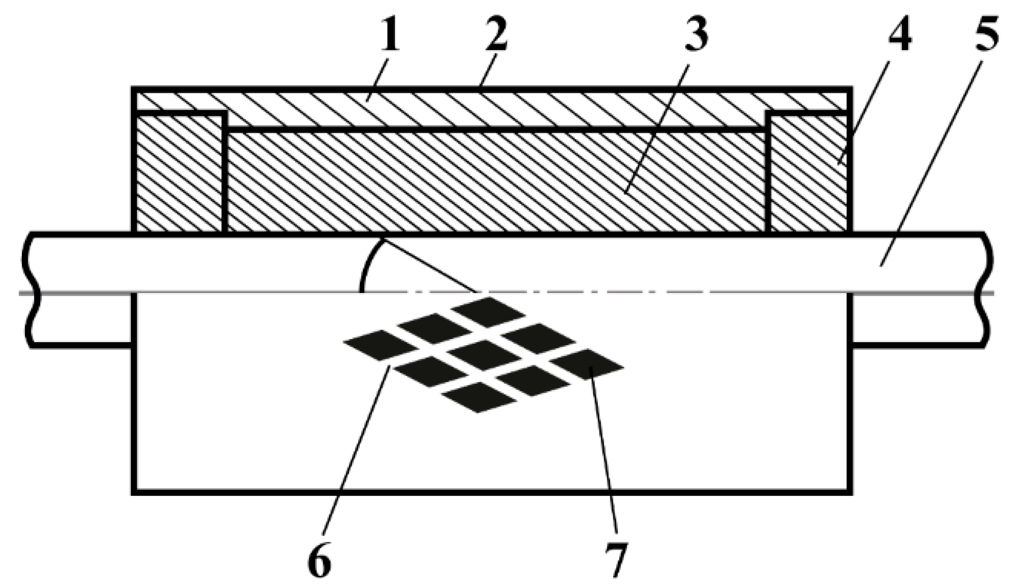
2.1. Problem Statement

The main objective of this work is to determine the conditions for the laser thermo-deformation sintering of an outer diamond-containing working layer of a certain width and thickness on a special rectangular insert for a cylindrical tool used for the surface grinding of products made of high-alloy steels, nickel and titanium alloys, glass, organoplastics, polymer composite materials, etc.
This technological operation is carried out with single- or multi-layer rectangular diamond abrasive inserts of a specific length from 100 mm to 600 mm and a width from 20 mm to 40 mm, depending on the overall dimensions of the drum.
The grinding diamond abrasive drum is a rotating cylinder with a diameter of D and a width of L. The working surface of the tool is discontinuous and consists of diamond abrasive working elements arranged with a certain pitch along the entire length of the drum. A working layer of composite containing synthetic diamonds of grades AC 15-N and AC 32-N, as well as AC15, AC20, and AC32, with grit sizes 500/400–200/160, is fixed on the outer surface of the drum inserts.
The process of forming a diamond-containing composite is as follows: On the surface of the part with a channel filled with a powder mixture of binder and diamond grains, the laser beam moves at a constant speed along the OX axis (Figure 2). The workpiece has the shape of a rectangular parallelepiped with a special groove for placing and laser sintering a layer of diamond-containing composite. The initial temperature of the workpiece is equal to the ambient temperature. The surface of the insert is exposed to a laser beam with a specific power distribution in the beam. This laser beam is focused on the surface to be treated and has the shape of an ellipse or rectangle with variable dimensions. The power distribution is described by using a law, which is set by a certain dependence or a grid of certain intensity values (or as a percentage of the total power) of the radiation directed to the treatment area.
Figure 2 gives a three-dimensional overview of laser thermo-deformation sintering. A gray rectangular block represents the metal drum insert—the heat-sink matrix onto which the composite layer is built. A groove machined into its upper surface is packed with a powder bed (orange color) consisting of a Ni–Cr–Co binder alloy premixed with mono-dispersed synthetic diamond grains. The global Cartesian frame (X, Y, Z) fixes the modeling domain: X spans the groove width, Y is the scan direction, and Z points into the substrate. At the origin, marked “0”, the surface is initially at ambient temperature.
Laser spot impinges on the powder, delivering a linear heat flux ql. The optics shape the beam into an ellipse or rectangle who’s in-plane power density follows a measured distribution: the center carries 100% of the normalized intensity, while the edges fall to about 28–29%, producing a smoothly peaked radial profile. Focusing places this footprint precisely on the powder surface. The beam then traverses the groove at a constant velocity v along the Y-axis, constituting a moving heat source in the transient thermal model.
As the spot advances, the irradiated region melts or partially melts; upon cooling it resolidifies into a composite track in which diamond grains are metallurgically locked at two-thirds of their height into the matrix. The dashed line drawn through the origin in the Z-direction highlights the depth over which temperature gradients are evaluated to ensure that processing remains within the safe thermal window (Tmax ≤ 1600 °C, t ≤ 0.3 s) that preserves the intrinsic strength of the diamonds. Thus the figure simultaneously conveys the geometry of the workpiece, the composition and location of the reactive powder, the characteristics and trajectory of the laser heat source, and the progressive formation of the dense diamond-bearing composite layer.
At the same time, the laser radiation causes a heat flux with a power density distribution on the surface of the workpiece.
This problem can be solved by modeling a situation where the powder material already fulfills the nominal channel of the metal inserts. To simplify the analysis, it is assumed that the mixture is in the form of a perfectly compressed powder and is a continuous layer of homogeneous material instead of a granular structure. The material of the powder layer melts as a result of laser radiation. The temperature field that occurs under the action of laser radiation on an insert that has the shape of a rectangular parallelepiped is described by a three-dimensional differential equation with specified initial and boundary conditions:
c ρ U t = λ ( 2 U x 2 + 2 U y 2 + 2 U z 2 ) ,
x [ 0 , L x ] ,   y [ 0 , L y ] ,   z [ 0 , L z ] ,   t [ 0 , T к ] ,
where c—heat capacity of the material to be processed; ρ—density of the material; λ—thermal conductivity of the material; Lx, Ly, and Lz—width, length, and thickness of the part, respectively; and Tk—simulation time.
Initial condition:
U x , y , z , 0 = U c ,
where Uc is the ambient temperature.
Boundary condition on the machining surface in the laser radiation zone:
λ U ( x , y , 0 , t ) z + q ( x , y ) = 0 ,
where q (x, y)—a function that describes the distribution of the radiation power.
Boundary condition on the workpiece surface outside the radiation zone:
λ U ( x , y , 0 , t ) z + α [ U ( x , y , 0 , t ) U c ] = 0 ,
Boundary conditions on other faces where heat losses are present:
λ U ( x , y , L z , t ) z + α [ U ( x , y , L z , t ) U c ] = 0 ,
λ U ( L x , y , z , t ) x + α [ U ( L x , y , z , t ) U c ] = 0 ,
λ U ( x , L y , z , t ) y + α [ U ( x , L y , z , t ) U c ] = 0 ,
λ U ( 0 , y , z , t ) x + α [ U c U ( 0 , y , z , t ) ] = 0 ,
λ U ( x , 0 , z , t ) y + α [ U c U ( x , 0 , z , t ) ] = 0
As the mathematical model consists of a three-dimensional nonstationary differential equation in partial derivatives, the finite difference method has been applied to solve this model, and the coordinate splitting scheme has been implemented using an adaptive grid.
For the temperature calculation, the dimensions of the part and the channel filled with a certain mixture, their thermophysical parameters (heat capacity, thermal conductivity, density, heat transfer coefficient), laser radiation parameters (shape and size of the laser beam, total power, power distribution in the focal spot, speed of movement), and calculation parameters (permissible error, size of the difference grid steps, and time steps) are specified.
These calculations result in the heat distribution over the part as a whole, namely, the temperature at each point of the part at any moment of the simulated time. On the basis of the data obtained, tables of temperature values in the nodes of a real uneven mesh are compiled. For more convenience and a better understanding of the process, it is advisable to visualize the results with two-dimensional graphs of temperature field isolines at the cross-sections perpendicular to the 0X, 0Y, and 0Z axes. These calculations are performed according to the algorithm (Figure 3). The software (version 1.0) was developed in cooperation with the Department of Automation of Design of Energy Processes and Systems, National Technical University of Ukraine “Igor Sikorsky Kyiv Polytechnic Institute”, to automate the calculations.
During the first stage of the calculation, the parameters of the environment, the thermal and physical characteristics of materials, the power and speed of the laser beam, and the temperature of the environment are specified (Table 2).
Then the distribution of laser radiation power (Figure 4) in the focusing plane of the laser beam is specified, specifically, the Gaussian distribution with the radiation intensity at selected points of the cross-section (a) and its volumetric representation (b). This reveals the shape of the laser beam focusing zone.
Figure 4a,b portray the same laser beam profile in two complementary graphic formats:
Figure 4a is a numeric contour map; the top-down map gives the relative power density across the beam footprint. The center is normalized to 100%, while the intensity drops to 28% at the extreme top and bottom points and to 29% at the far left and right. Intermediate points (or contours) fill in the smooth radial decay between these limits, clearly visualizing how the energy falls off from the core toward the periphery.
Figure 4b is a volumetric representation showing the same distribution in depth: the laser energy penetrates most deeply at the beam center and diminishes progressively toward the edges of the spot (or its circumference), mirroring the percentages given in Figure 4a.
Together, Figure 4a,b confirm that the laser beam has a centrally peaked, radially symmetric intensity profile, with power density and penetration both tapering from the core to the rim.
Finally, the calculation parameters are set, including the range of the axis and time steps, the final calculation time, the maximum allowable error, etc. (Table 3). After that, the calculation process is performed. The analysis of the generated data table allows for the temperature distribution in the nodes of the difference grid in the section along any axis to be observed.

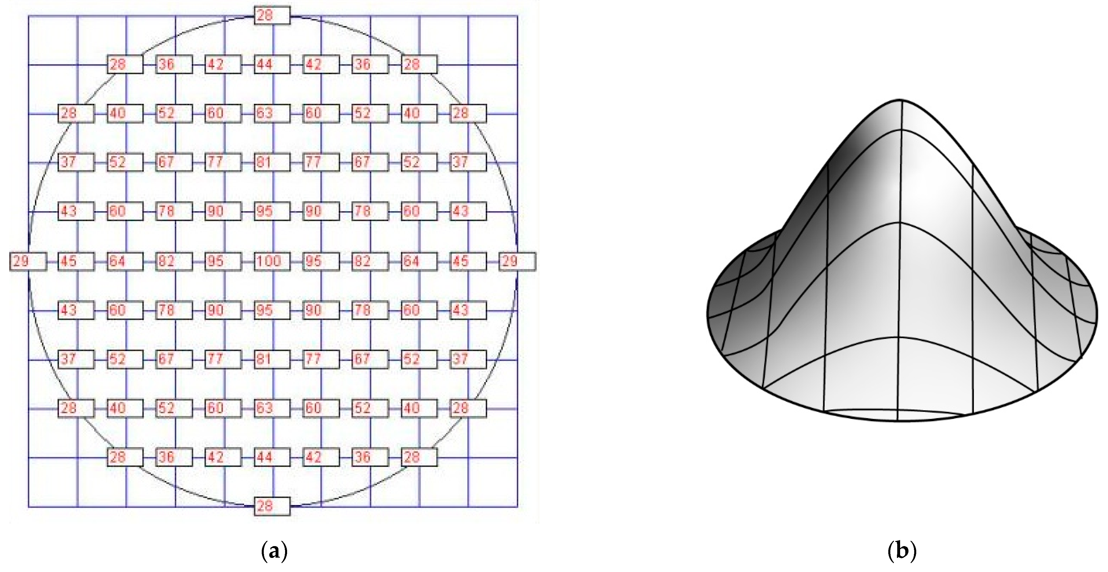
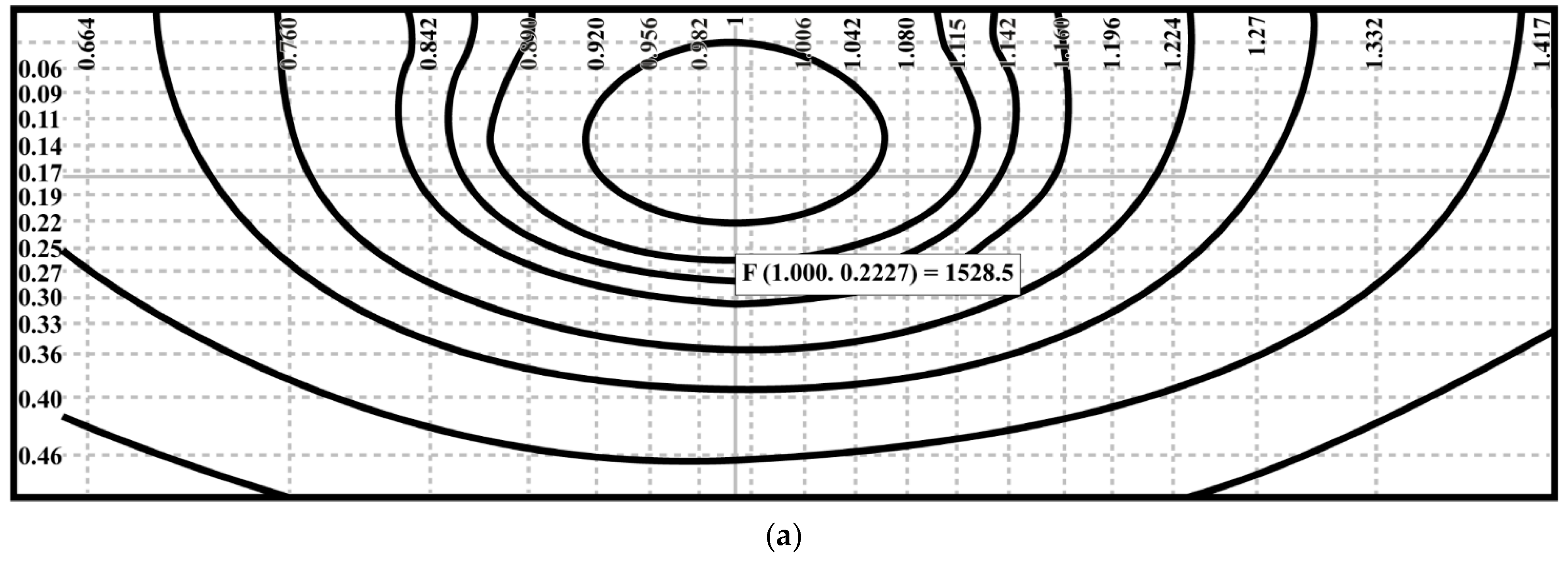
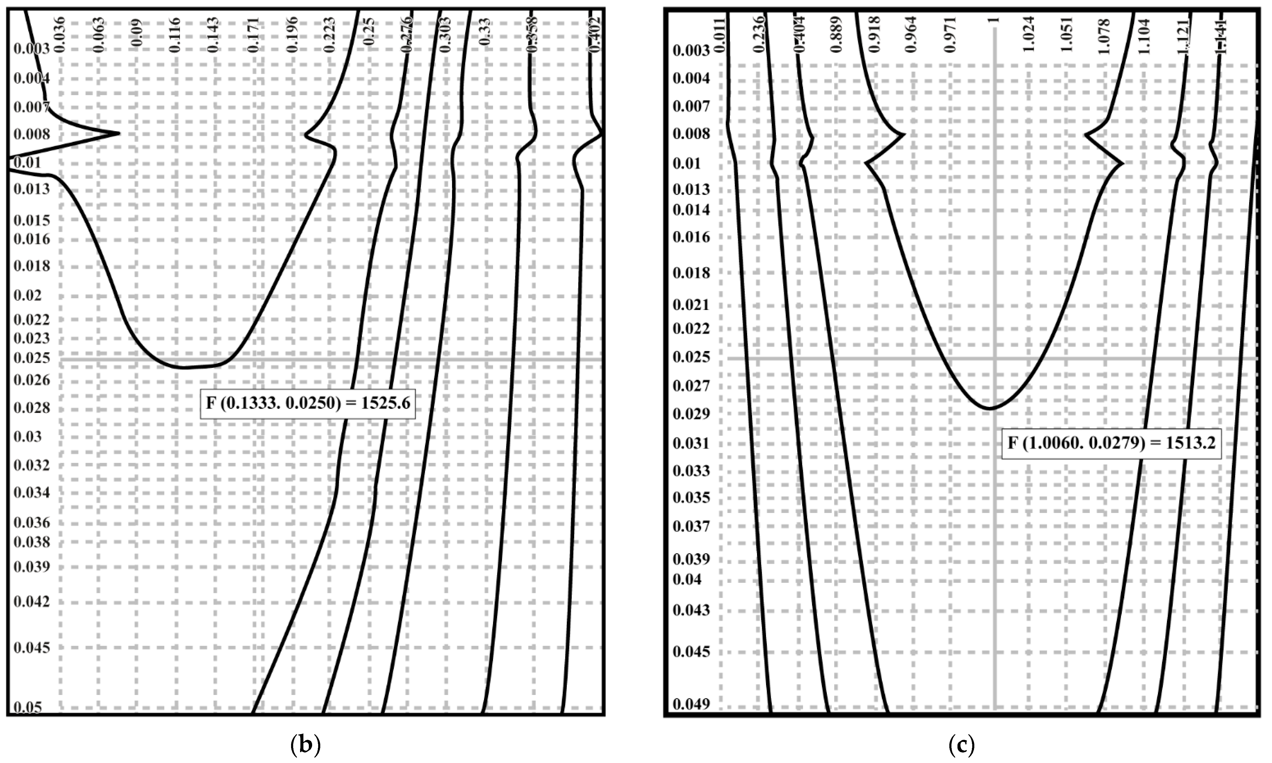
2.2. Calculation Results

Numerical analysis of laser sintering reveals the temperature distribution across the difference grid nodes. The data highlight thermal behavior along various axes, critical for process optimization.
Figure 5 illustrates the laser sintering rate’s dependence on the diamond-containing layer’s thickness and laser focusing zone’s size. This relationship guides the selection of laser parameters for efficient sintering. Table 4 details the composite displacement rate during laser sintering (1.06 μm, 1500 W), varying with layer thickness and focusing zone diameter. These results inform mechanical performance under laser processing. Figure 6a maps the temperature distribution on the HTN composite surface in the X0Y plane, while Figure 6b,c show the longitudinal (Y0Z) and transverse (X0Z) sections. These findings underscore the impact of laser parameters on thermal and mechanical outcomes, enabling precise control in manufacturing diamond-containing composites.
Figure 6 shows the temperature distribution on the surface of the HTN composite layer in the coordinates X0Y (a) and along the longitudinal Y0Z (b) and cross-sections (c) of the fusion zone with the base of the 40Cr4 steel inserts.
It is established that the zone of application of the deforming force should be located at a distance of 16 mm from the beam axis, and its value should be varied in the range of 30–50 kgf.

3. Materials and Methods

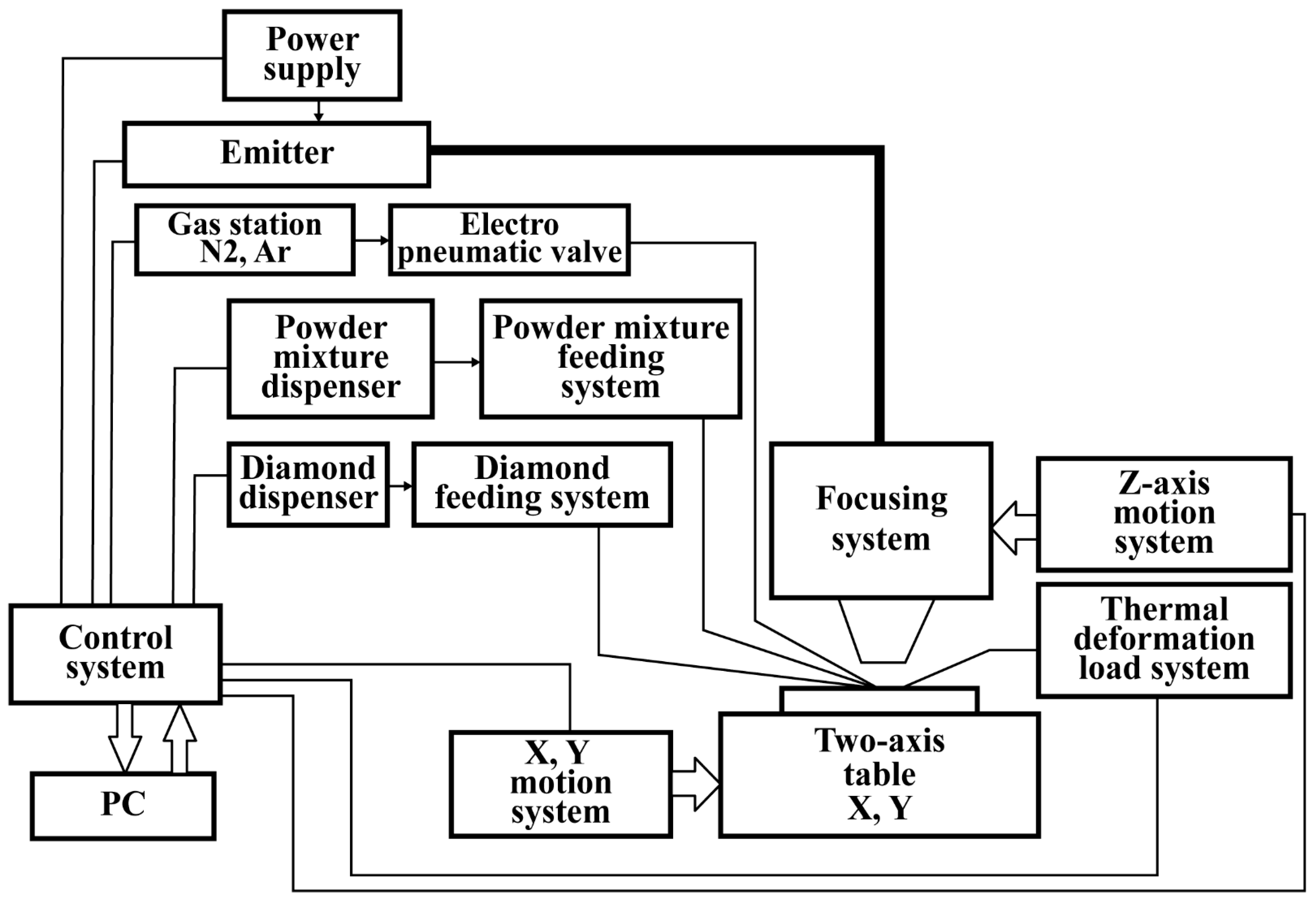
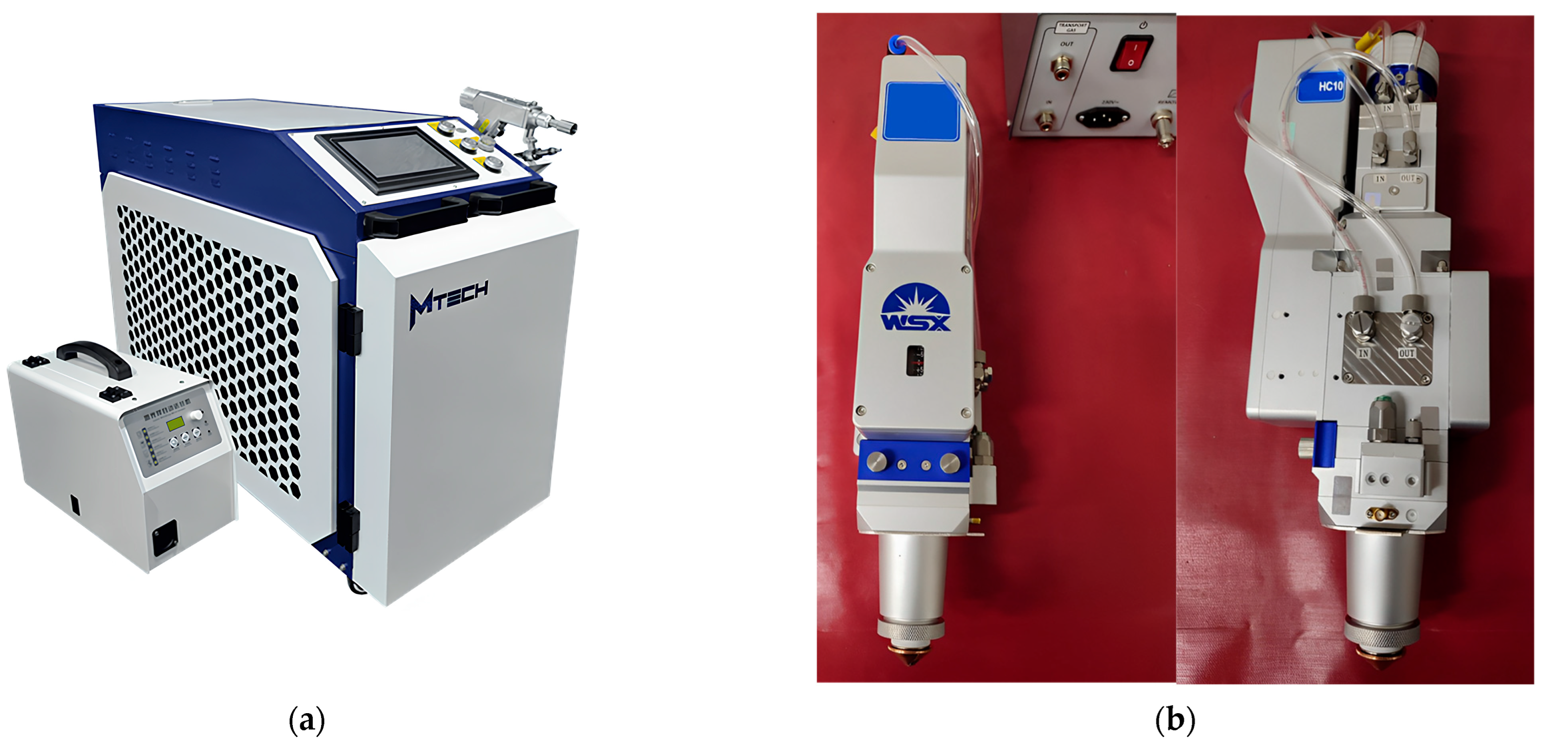
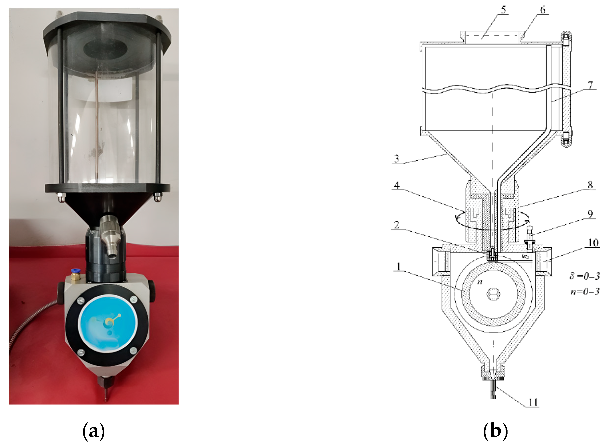
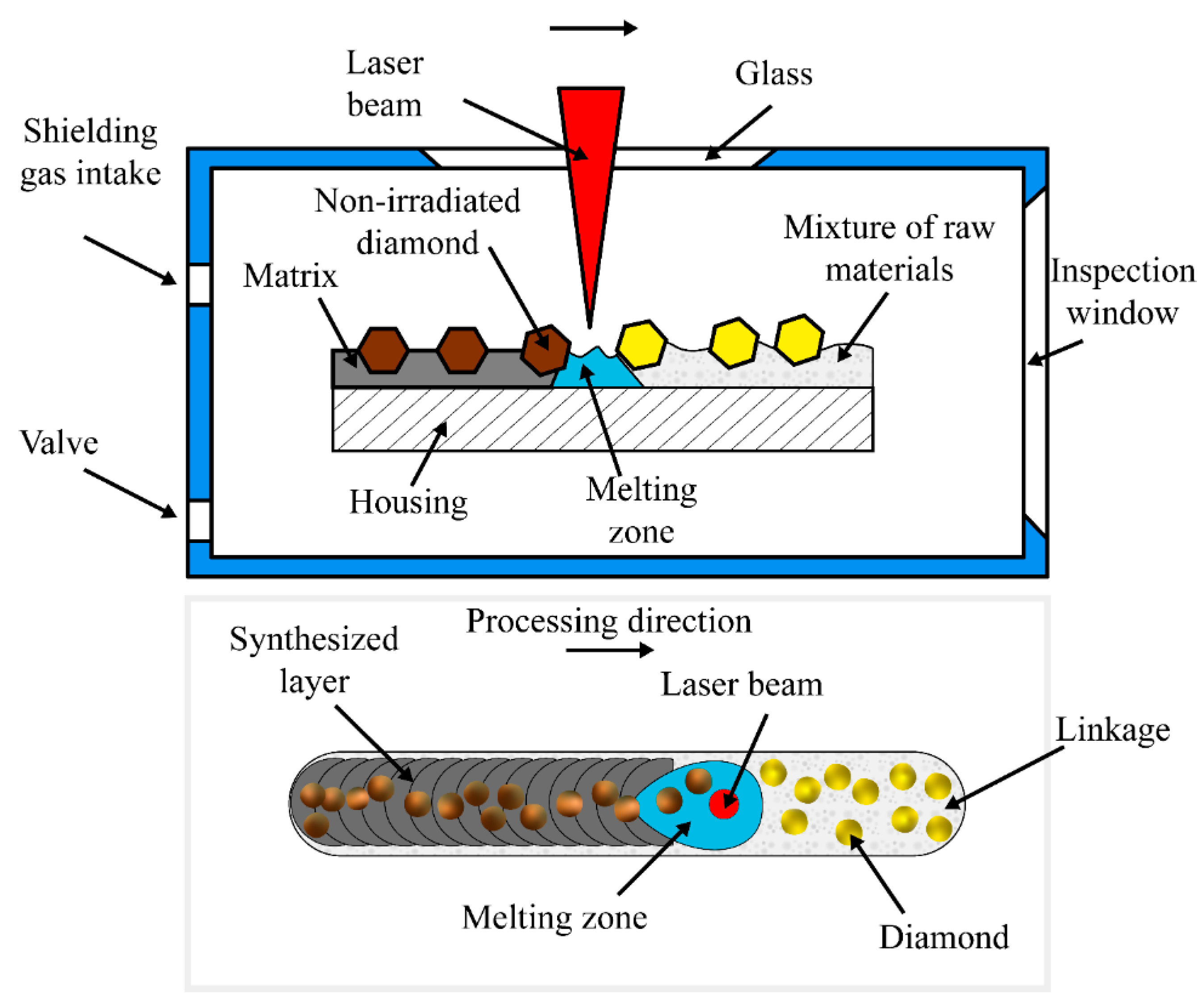
3.1. Experimental Equipment

Experimental research of the process of the laser thermo-deformation sintering of a diamond-containing layer on the surfaces of tool drum inserts was carried out using laser technological equipment, the block diagram of which is shown in Figure 7.
The system includes laser processing units equipped with a 4th generation Maxphotonics fiber optic laser emitter that generates both pulsed (up to 30 J) and continuous radiation with a power that can vary from 50 W to 1500 W, and with a power supply unit (Figure 8a). The equipment is designed for surface hardening, microalloying, and surfacing, and has high efficiency and increased performance.
The system also includes a technological module, which consists of a machine for moving the workpieces relative to the laser beam, a laser focusing and scanning system (Figure 8b), a device for dosing and feeding powder bonding (Figure 9), and a system for controlling the supply of diamond grains to the sintering zone (Figure 10). WSX laser focusing system: NC30A 0–3 kW auto-focus (driver kit) FL150. The WSX NC30A laser head with the auto-focus function (Figure 8b) contains a fiber optic interface (QBH, QD) and features a convenient replacement of the protective lens. The internal design has a high degree of sealing, which prevents the contamination of the optical lens by the external environment, and helps to increase the service life of the optical lens.
The device for the dosage of the powder mixture (Figure 9) is made in the form of a drum with longitudinal notches 1 and a movable tube 2 vertically located above them, through which the powder is poured into the hopper 3 on the drum. The tube is rigidly connected to the hopper by screws and moves with it when the working gap δ is adjusted. The drum of the device is driven by a stepper motor Fl57STH76-2804A.
The powder flow rate is adjusted coarsely by changing the gap between the tube and the drum and precisely by changing the drum rotation speed n. The gap adjustment range is 0–3 mm and the drum rotation speed is 0–30 rpm. The range of working gaps is 0.5–1.5 mm. Larger gaps (>1.5 mm) are used to remove powder during powder replacement or the completion of work. The required gap is set using the adjusting nut 4, on the top of which there is a scale showing hundredths of millimeters. One turn of the nut changes the gap by 1 mm.
The powder feed is controlled by the operator’s touch panel. The hopper capacity is 3.5 L, which can hold up to 15 kg of powder. The powder is transmitted to the laser beam area by a transport gas (argon). Part of the gas is supplied to the hopper through channel 8 and tube 7 to balance the gas pressure as the powder is being consumed, as well as to prevent air from entering into the deposition zone.
During the final stage, one or more layers of a diamond-containing composite of a given width and thickness are formed over the entire surface of the metal inserts. At the same time, a powdered mixture of bonding and diamond grains is simultaneously fed into the laser exposure zone with a specified flow rate by a transport gas (Ar). To regulate the consumption of diamonds, a special dosing device was developed, shown in Figure 10. The main part of the dosing device is a drum consisting of a pipe with through holes made with a certain pitch over the entire surface. The holes with a diameter of 0.2–0.6 mm (depending on the size of the diamond grains) on the outer part of the pipe are conical in shape. The larger diameter of the cones is twice the average size of the diamond grain. At the beginning of the dispenser’s operation, a certain number of diamonds are fed into the upper part of the vibrating hopper body through the counter.
At the same time, the dosing drum, driven by a stepper motor, rotates around its axis, with the drum holes entering the area where the diamonds are located. The diamond grains move further due to the reduced pressure in the inner part of the drum created by a vacuum pump connected to one of the ends of the drum axis. In the direction of rotation, the diamond drum tube enters the tightly fitting metering housing. At the same time, the diamonds are held in this area by a vacuum and the tight fit of the pipe to the body. This arrangement ensures that only one diamond grain is guaranteed to be present in the drum cone.
As the pipe rotates, the diamonds move with it to the lower part of the dispenser and fall into the groove of the body and then, under the influence of gravity, move out of the cones and enter the sintering zone in a dosed manner. In order to prevent diamonds from getting stuck while passing through the hole in the axle and then the internal groove in the sleeve, air with a pressure of 2–3 atm is supplied from the compressor, which blows the diamonds out of their cones in the pipe. The diamonds are then transported to the sintering zone through a special channel. After that, the formed diamond-containing composite is compacted by a roller as it moves 16–20 mm from the center of the laser beam.

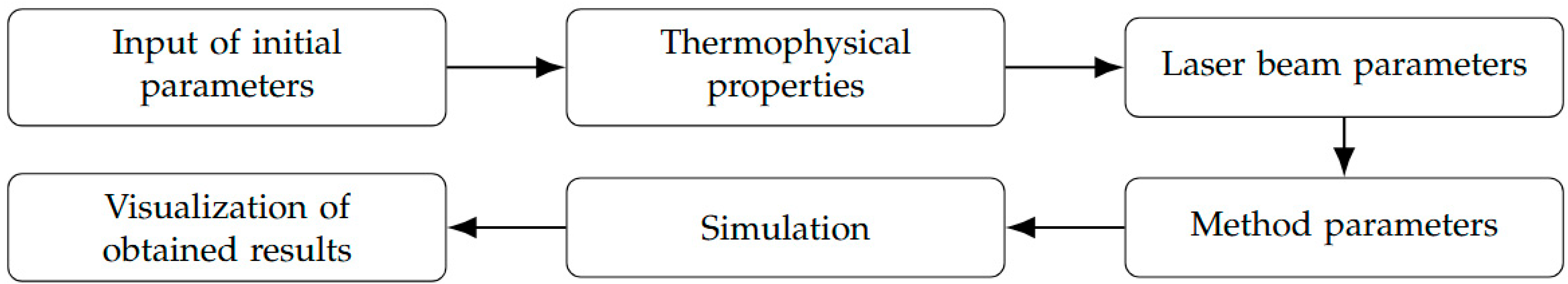
3.2. Research Methods
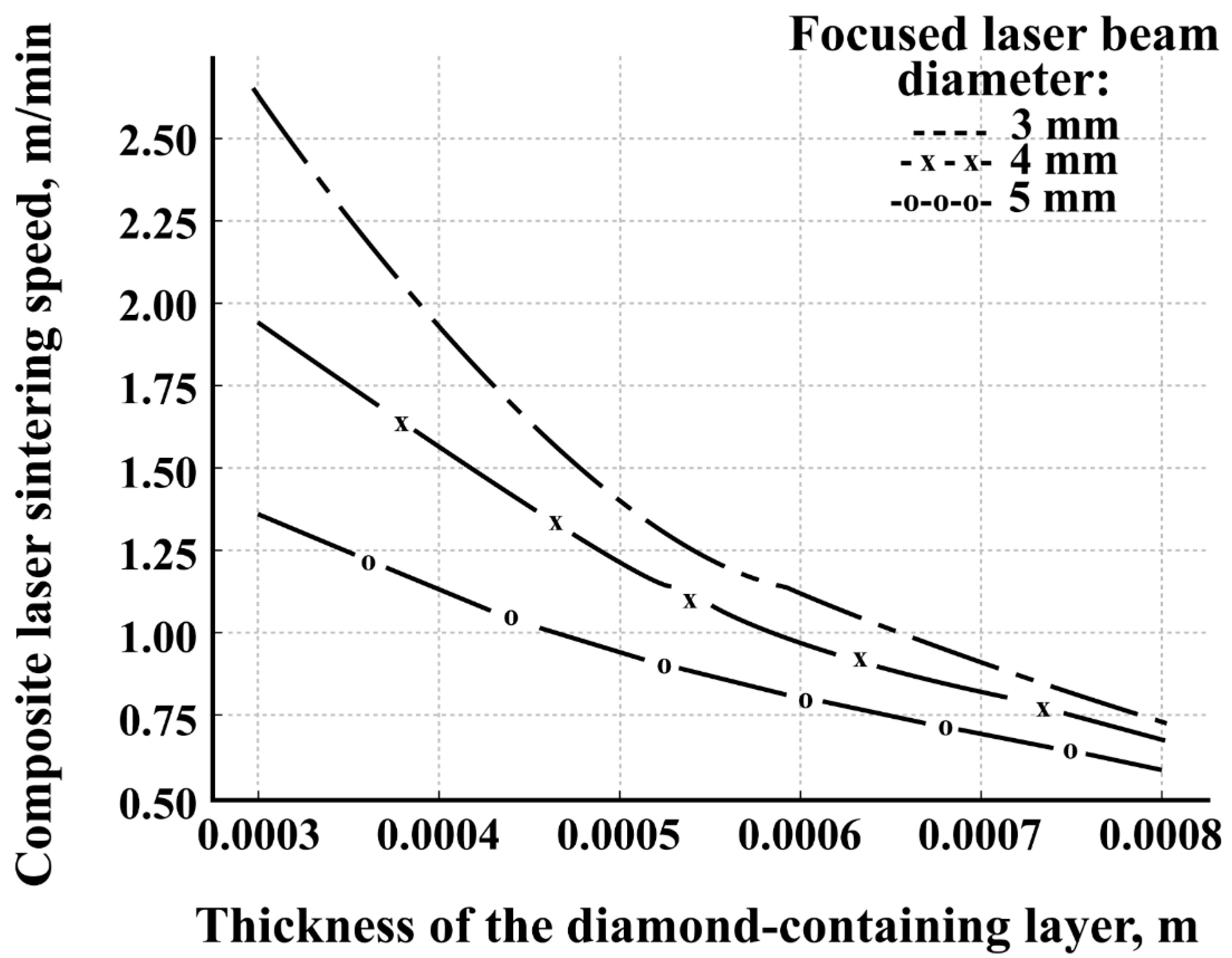
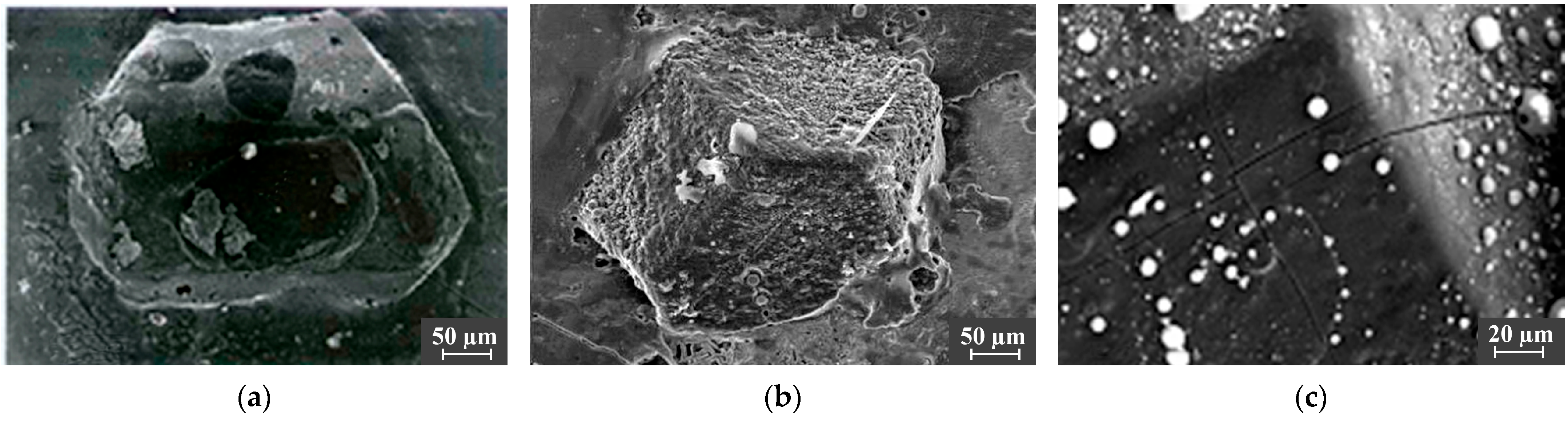
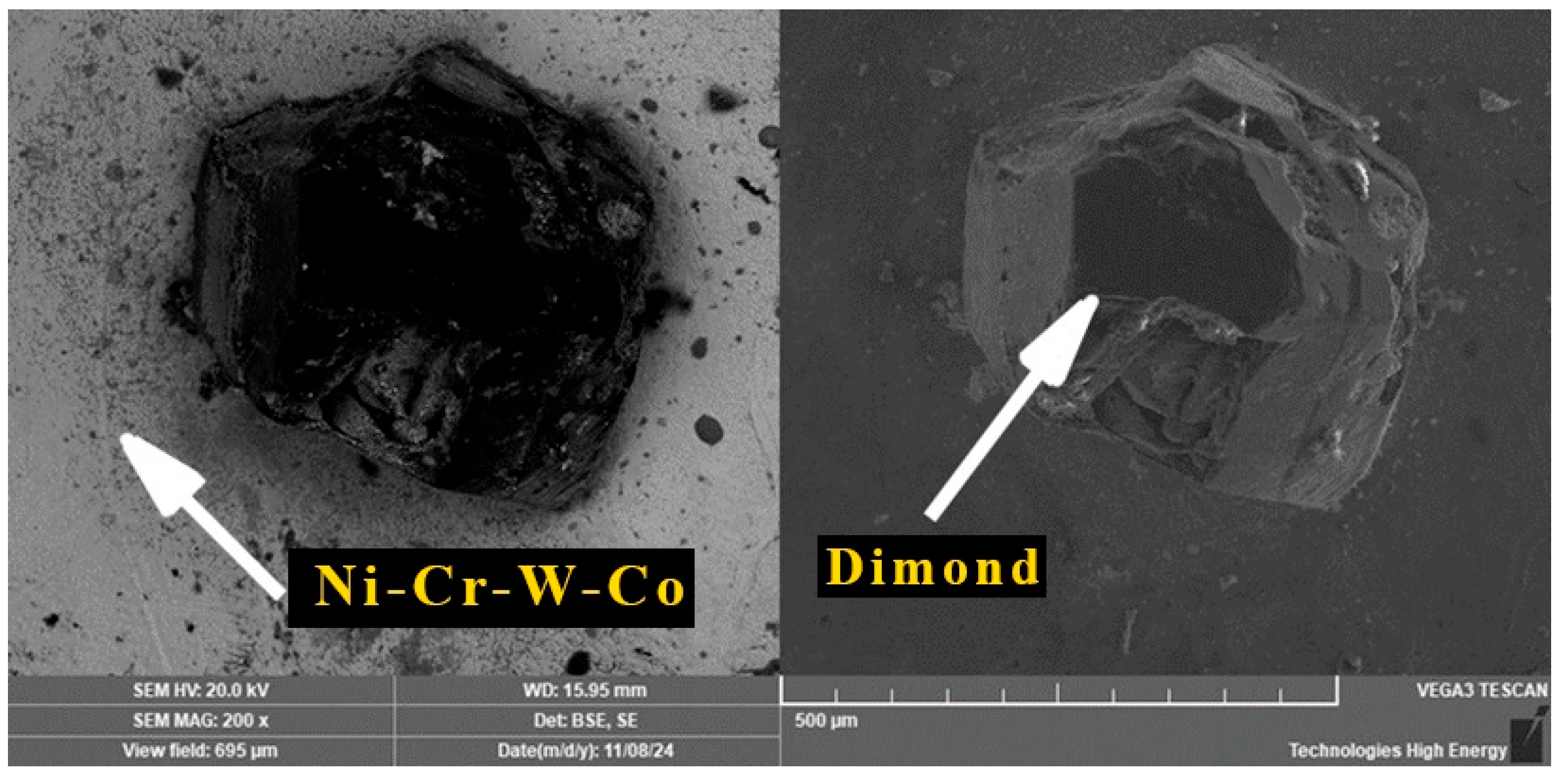
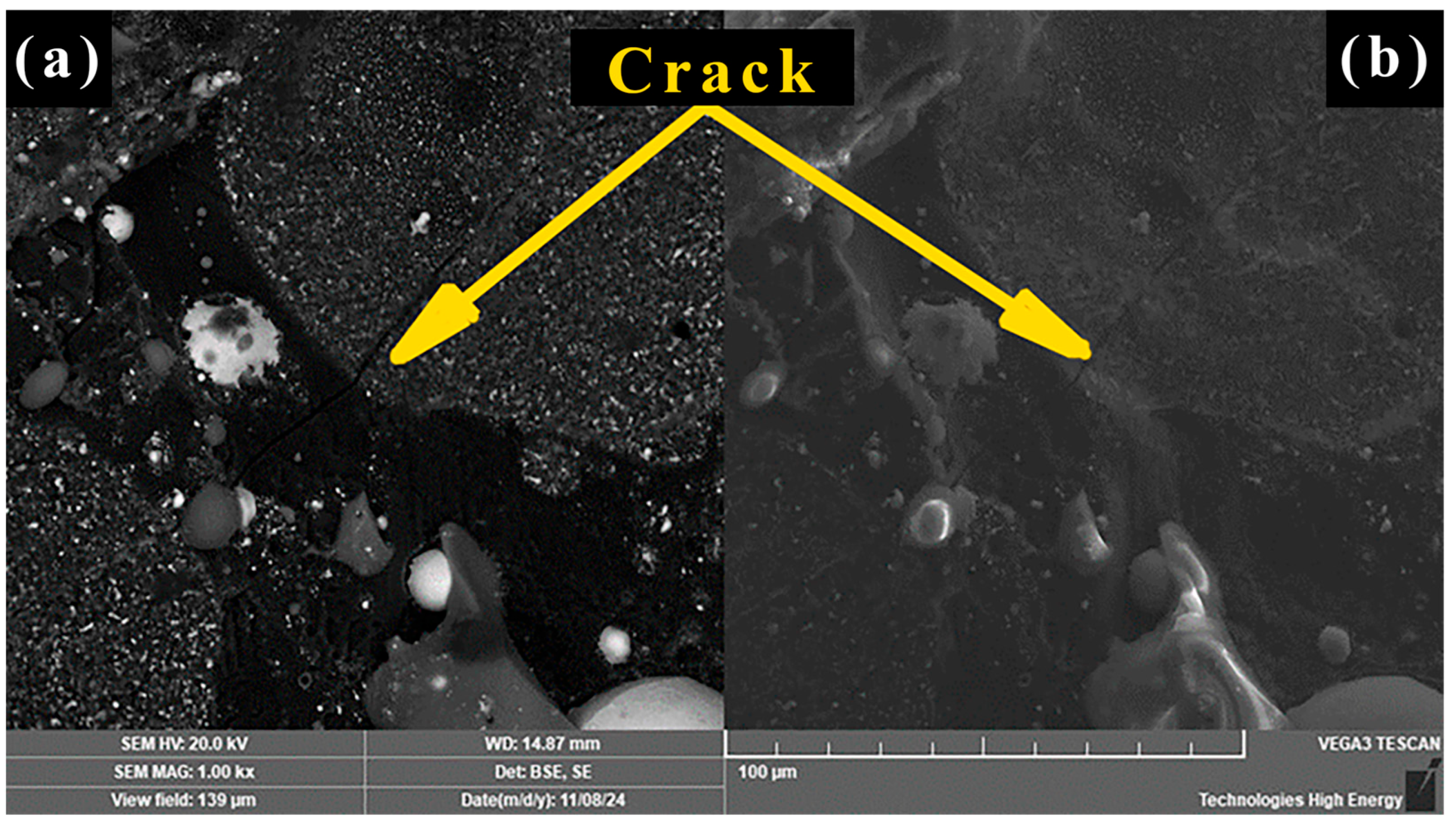
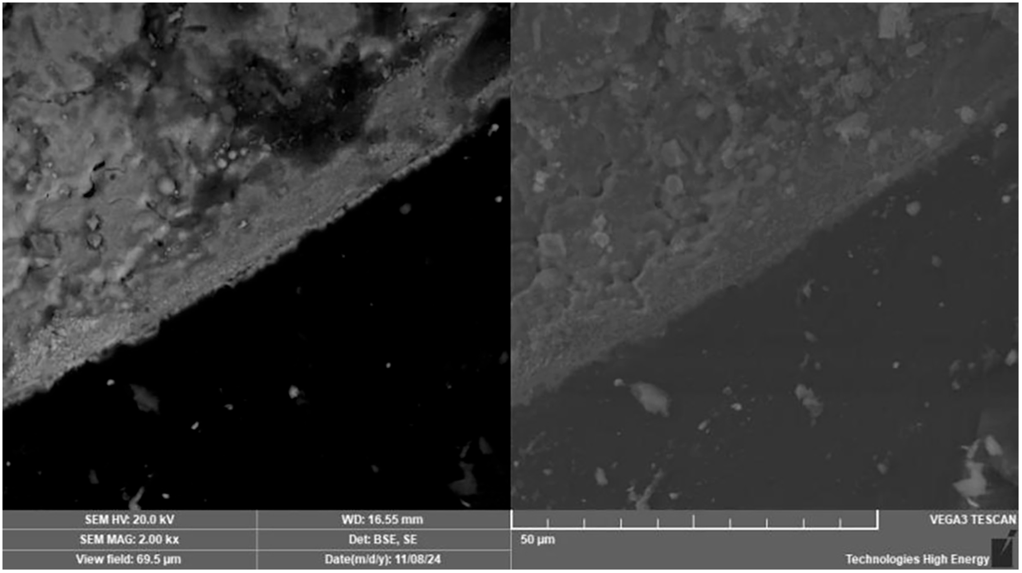
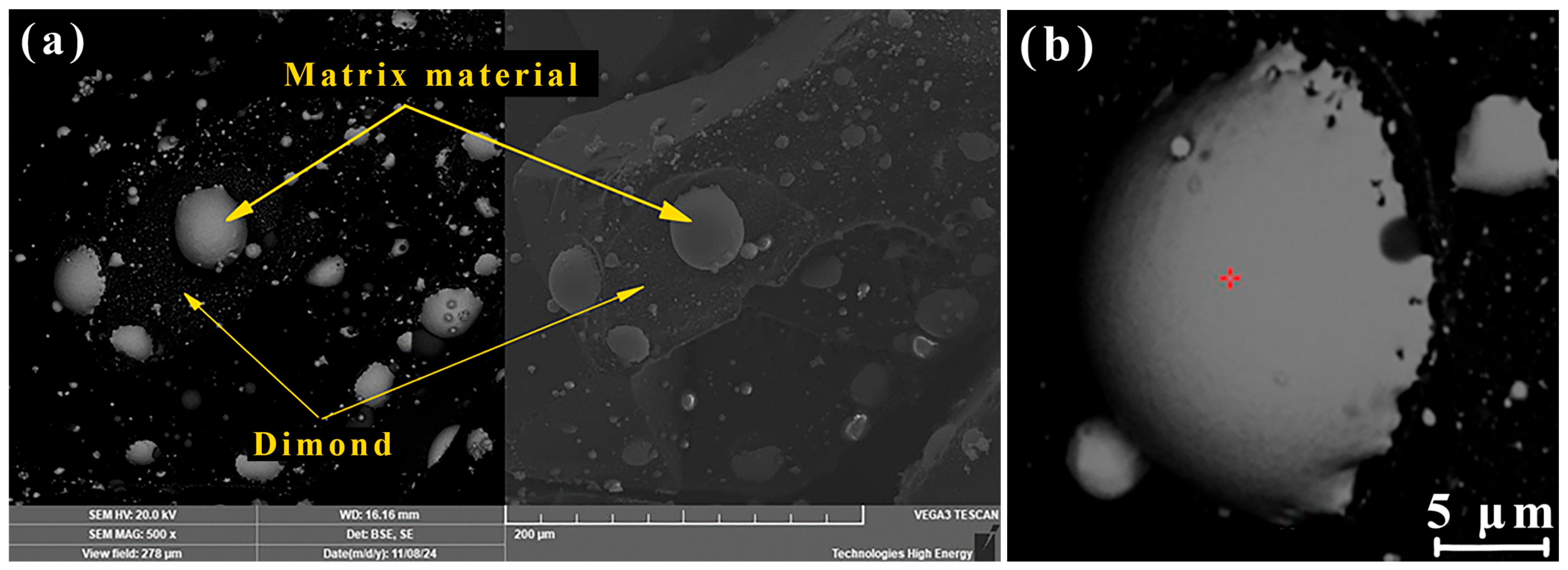
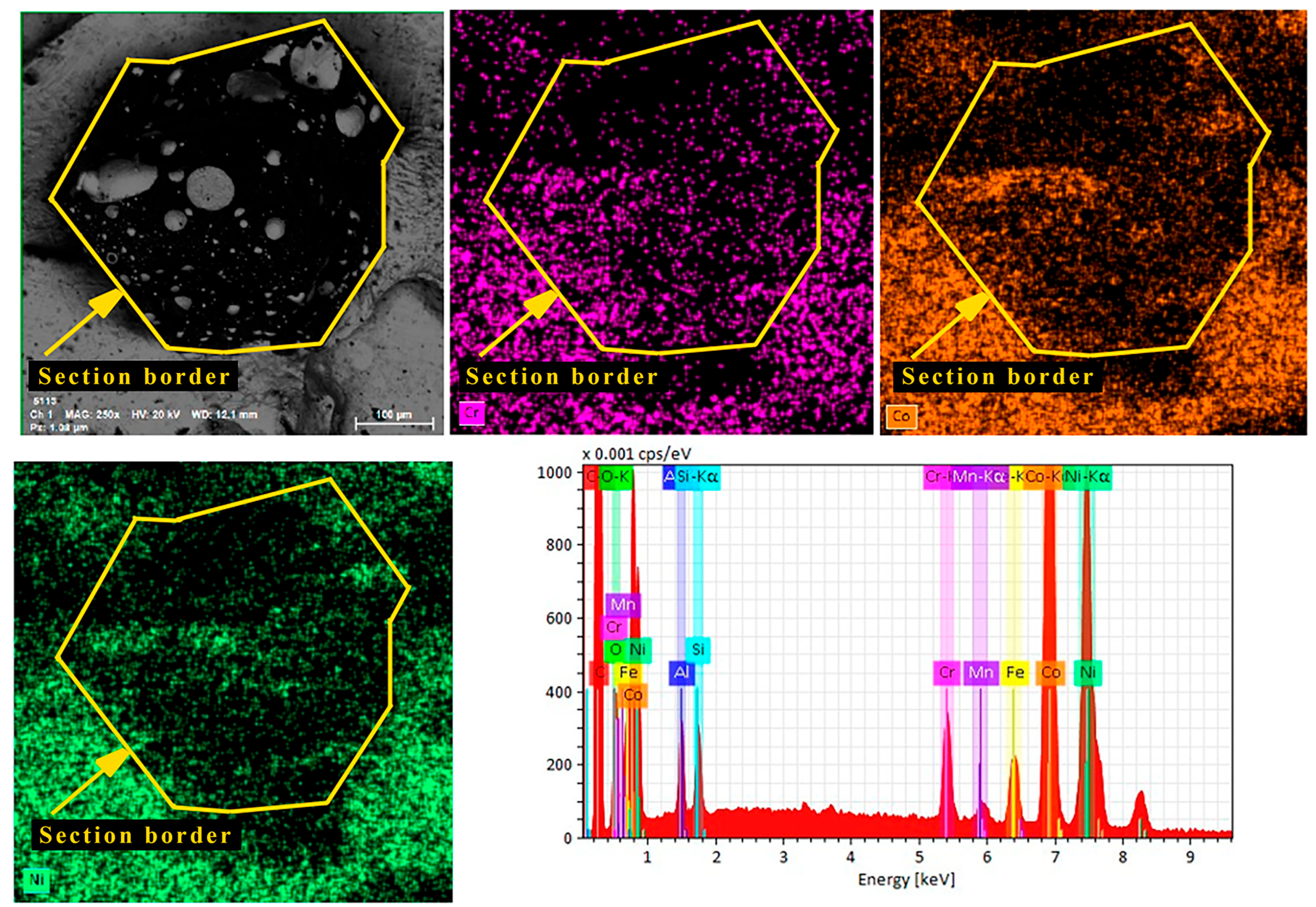
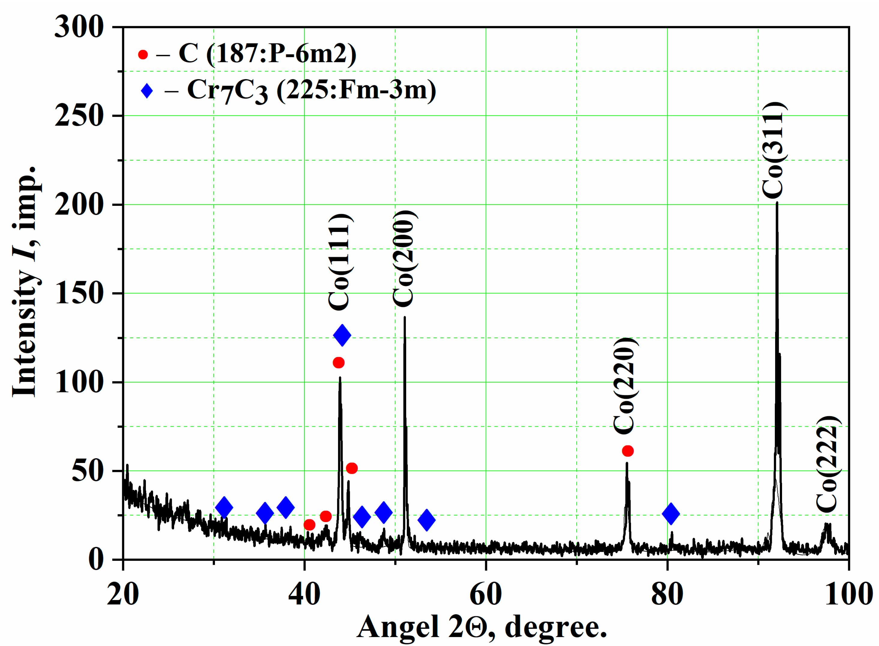
For the implementation of the process by laser synthesis of abrasive layers, it is necessary to establish the optimal technological parameters at which the tool properties of synthetic diamonds are preserved and the formation of a metal matrix takes place. As abrasive grains, the synthetic diamonds of the AC125 grade with a grain size of 425/300 (static grain strength of 166 N) were used. Nickel-based powders (PS-12N-VK) and iron-based powders (12KH18N10T + TiB2 + CrB2) with a spherical shape of 50 microns were used as a bonding agent. The bond and synthetic diamond grains (the concentration of which was 20% by weight of the bond) were mechanically mixed for three hours in a powder mixer device and applied to the surface of the metal plate using end measures with a layer thickness of 1 mm. To fix the joint on the plate surface, the former was moistened with a cementitious adhesive.
The technological parameters of processing varied in the following ranges: power density—Wp = (1.77 − 3.54) × 103 W/cm2 and processing time—τ = 0.18–1.8 s. Laser treatment was carried out in an argon environment after the chamber of the device was completely filled with inert gas (Figure 11), the flow rate of which was 20 L/min.
Following the synthesis of the composite, the surface morphology of the samples was examined using a scanning electron microscope (SEM, TESCAN VEGA3).
To expose typical cross-sections, the samples were cut, after which the cross-section was successively polished with abrasive and diamond paper.
The X-ray diffraction studies of the obtained composites were carried out using a Rigaku Ultima IV diffractometer (λKα-Cu radiation): angle interval—2Θ = 20–120°, registration step—0.04°, dwell time at a point—2 s, voltage—40 kV, and current—40 mA. The PDXL software and the international diffraction database ICDD (PDF-2 (2025) were used to analyze the obtained X-ray spectra; calculate the size of coherent scattering regions (CSR) and the degree of lattice deformation (ε); and conduct quantitative phase analysis. Quantitative phase analysis was performed by the RIR (Reference Intensity Ratio) method, which involves comparing the intensity ratio of the strongest phase reflexes and corundum in their mixture with mass fractions.

4. Results

During the laser sintering process of composites based on synthetic diamonds and the most widely used binders based on NiCrBSi (PGSR-4), iron (12KH18N10T + TiB2 + CrB2), powder mixtures of PS-12N-VK, and others, it is usually practically impossible to ensure tight thermal contact between the components due to the poor wettability of the diamond surfaces by the binder melt (Figure 12a). Therefore, to eliminate such an issue, cobalt (Co) was added to the bonding composition, because its melt wets the diamond surface well, forming a dense developed film (Figure 12b). When the maximum possible heating temperature is exceeded (>1600 °C), cracks first form in the composite diamonds along the crystal bonding plane, and then, with a further increase in temperature, they form across the edge (Figure 12c). In the presence of cobalt in the bond, its other components also tightly cover the diamond grains.
Figure 13 shows the surface morphology of diamond grains after the laser synthesis process in the optimal operating range of irradiation conditions. The analysis of the appearance of the diamond grains removed from the bond showed that their edges and corner surfaces were clean, without any obvious traces of graphitization or damage. The diamond grains are located in the melt of the bond at two-thirds of their height. Due to the incorporation of cobalt in the composition of the bond, we observe good wettability of the diamond surfaces by the metal of the Ni-Cr-Co bond. The laser treatment was carried out in an inert environment of argon. It can be seen that there is no coating on the surfaces of the diamonds that protrude above the bond, and the cutting edges are practically open. The immersion depth of the diamond grain meets the necessary requirements.
Based on our previous research [13], to verify that the diamonds retain their initial mechanical integrity after processing, a two-stage strength evaluation was performed. First, we reproduced the single-particle compression (“crush-test”) method based on article [13] on 125 µm and 160 µm synthetic diamonds. In agreement with their findings, fast heating within 0.09–0.30 s to 1500–1600 °C caused only a marginal drop in fracture load; for example, at Wp = 1.7 × 10³ W cm−2 and τ = 0.09 s, the maximum load declined by merely 3%. Second, ten AC125 grains were extracted from composite inserts produced in this study at P = 500 W, v = 0.5 m min−1, and d0 = 3 mm (effective irradiation time ≈ 0.27 s). Their mean fracture load was 165 ± 5 N versus 166 ± 4 N for pristine control grains from the same batch; a two-tailed Student’s t-test yielded p = 0.41, confirming that any strength difference was statistically insignificant. Scanning electron micrographs of grains embedded two-thirds of their height into the Ni–Cr–Co matrix (Figure 13) show crack-free edges and the absence of graphitization, further corroborating strength retention. These results prove that processing inside the validated safe thermal window (Tmax ≤ 1600 °C, t ≤ 0.3 s) maintains the original strength of the diamonds after sintering.
Figure 14 shows the surface of a composite containing a diamond grain and bonds in which cracks have formed during laser sintering. Noticeable is the long crack that formed in the bond (left) and especially the crack in the diamond crystal that is directed across its edge (right).
The main cause of the formation of these cracks is the elevated temperature of laser heating and the conditions of heat transfer. The previously established fact that synthetic high-quality diamonds lose their strength during laser heating to temperatures exceeding 1500 to 1600 °C for more than 0.3 s has been confirmed. One of the possible explanations may be a significant difference in the linear expansion coefficients of the bond and the diamond. It can be assumed that the diamond is subjected to excessive shear stress at the origin, and some cracks are expected to occur even under light load. The boundary shrinkage due to melting and crystallization (for Ni-Cr-Co alloy: ~10 × 10−6/°C) and the linear expansion of the diamond (1 × 10⁻⁶/°C) are significantly different. A certain tensile force occurs between the bond and the diamond grain. The shrinkage that occurs in this case is not synchronized with the deformation of the diamond, which at the macroscopic level leads to the formation of cracks. However, under certain optimal conditions of laser thermo-deformation sintering, it is possible to ensure the tight coverage of the diamond with the bonding material without cracks and other defects (Figure 15).
In accordance with the energy spectrum of the linear scanning of the abrasive surface (Figure 16a), the segregation of Cr and Co elements is observed, which is determined by an increase in their concentration on the diamond surface and a smoother movement to the carbon surface (Figure 16b). By summarizing the results achieved, it can be assumed that some carbide compounds of chromium, cobalt, and tungsten are formed in the zone between the diamond and the bond, which contribute to more efficient wettability of the diamond surface. This certainly indicates that the proposed process of laser synthesis of the working layers of diamond abrasive tools based on the mechanism of laser sintering is promising for extensive use in various industries.
According to Figure 17, for a more accurate assessment of the state of the diamond–bond, a linear EDS scan was performed and the distribution of elements in the transition layer at the interface between the diamond and the Ni-Cr-Co bond was determined. An increased Co concentration was observed, indicating good wettability of the diamond surface during the laser synthesis process. Since the presence of Co in the transition layer improves the wetting of diamond surfaces by the bond, the bond strength between the diamond and the bond is obviously improved. In general, a uniform distribution of binder elements is observed due to the intensification of their concentration redistribution processes in the process of laser synthesis of diamond-containing composite layers.
For determining the possibility of the formation of Cr carbides in a bond during laser synthesis, a phase analysis was performed, the results of which are shown in Figure 18. The diffraction peaks from the solid solution based on cobalt, carbon, and chromium carbide Cr7C3 were detected. The results of determining the quantitative phase composition indicate that the content of chromium carbide Cr7C3 in the formed diamond-containing composite is ~7 wt.%, and artificial diamonds are ~13 weight.% (the basis, respectively, is an HCC solid solution based on cobalt ~80 wt.%).
During the laser sintering process, carbon on the diamond surface interacts with chromium, which is a component of the Ni-Cr-Co bond. The formed Cr7C3 carbide grains subsequently grow epitaxially. The process of carbide formation is accompanied by a decrease in the interfacial tension between the diamond and the bond, which improves the wettability of the diamond by the bond material.
Considering that the value of the linear expansion coefficient of Cr carbide is between the values for diamond and bond, this allows us to eliminate the expected effect of stress concentration caused by the difference in the linear expansion coefficients of diamond grains and bond. Consequently, the Cr carbide layer has a sufficiently high adhesion strength to the diamond, and at the same time, high thermal conductivity.
It is important to note that the size of the coherent scattering regions of Co and Cr7C3 carbide are practically the same and are within 200 nm, while the degree of deformation of the Co lattice is ε = 0.7%, and that of the carbide is much smaller, 0.3%, which is also a positive factor.

5. Conclusions

The process of laser thermal deformation sintering with an original system of a controlled and strictly dosed supply of synthetic diamond grains to the binder melt for the synthesis of abrasive composites on the working surfaces of a drum-type tool has been developed. According to estimates, this will radically (more than 20 times) increase the productivity of such an abrasive tool for processing large-sized sheet parts, reduce the cost of its manufacture, and expand the scope of application while maintaining high quality. It is also possible to use metal bonds of different hardnesses and the programmable placement of abrasive grains on the working surface and to thus reduce diamond consumption and form single- and multi-layer working tool surfaces with the increased adhesion strength of abrasive grains to the bond.
A new original design of a cylindrical tool drum is proposed, which contains a system of interchangeable metal inserts arranged with a certain pitch and angle of inclination to its axis along the forming line, on the surfaces of which a diamond-containing layer of controlled thickness is applied by laser sintering, which can vary depending on production needs. An effective method of fixing inserts with a diamond-containing layer on the working surface of the tool has also been developed to reproduce the stable position of the abrasive layer relative to the drum axis, as well as to quickly replace the inserts and thus reduce the time required to repair worn elements.
The expediency of using a cobalt-based alloy as a binder, which improves the wettability of diamond surfaces and the contact density in the transition layer at the interface between diamonds and a Ni-Cr-Co binder, has been proved. During laser sintering, carbon and chromium interact on diamond surfaces to form Cr7C3 carbide. The carbide formation process further improves the wettability of diamonds and reduces the stress level caused by the difference in the coefficients of linear expansion of diamond grains and bonds. As a result, the formed layer of Cr carbide improves not only the bonding strength of diamonds with the substrate, but also thermal conductivity.
In summary, laser thermo-deformation sintering with independent diamond dosing establishes a production-ready alternative to nickel-electroplated or hot-pressed drums. Through (i) a tightly bounded thermal window validated by simulation and SEM/EDS evidence, (ii) cobalt-assisted wetting plus an in situ Cr7C3 transition layer, and (iii) a modular insert-on-drum design, the proposed route achieves crack-free bonding, programmable grain layouts, and >20-fold productivity gains over legacy methods. These results position the process as a scalable solution for large-panel grinding in aerospace, shipbuilding, and composite-machining sectors.

Author Contributions

Conceptualization, L.G., O.G. and O.K. (Oleksii Kaglyak); methodology, L.G., O.G., S.V. and O.K. (Oleksii Kaglyak); software, O.G. and S.V.; validation, O.K. (Oleksii Kaglyak), O.G. and S.V.; formal analysis, O.K. (Oleksandr Kapustynskyi); investigation, O.K. (Oleksii Kaglyak), O.G. and S.V.; writing—original draft preparation, L.G.; writing—review and editing, O.K. (Oleksandr Kapustynskyi) and N.V.; visualization, O.K. (Oleksandr Kapustynskyi); supervision, L.G.; project administration, L.G. and O.K. (Oleksii Kaglyak); funding acquisition, L.G. All authors have read and agreed to the published version of the manuscript.

Funding

This research was funded by National Research Foundation of Ukraine, grant number 2023.04/0051. Project: “Synthesis of diamond-containing composites through thermodeformation laser sintering for abrasive machining of large components in aerospace, shipbuilding, and machinery industries” (No. 0124U003940).

Data Availability Statement

The data presented in this study are available on request from the corresponding author.

Conflicts of Interest

The authors declare no conflicts of interest.

References

  1. Lavrynenko, V.I.; Novikov, M.R. Nadtverdi Abrazyvni Materialy v Mekhanoobrobtsi: Entsyklopedychnyi Dovidnyk; INM im. V.M. Bakulia: Nanu, Ukraine, 2013; p. 456. [Google Scholar]
  2. Huang, C.A.; Shen, C.H.; Li, P.Y.; Lai, P.L. Effect of fabrication parameters on grinding performances of electroplated ni-B-diamond tools with D150-Diamond Particles. J. Manuf. Process. 2022, 80, 374–381. [Google Scholar] [CrossRef]
  3. Huang, C.A.; Shen, C.H.; Huang, W.Z. Grinding performance of electroplated diamond tools strengthened with Cr-C deposit using D-150 diamond particles. Int. J. Adv. Manuf. Technol. 2022, 121, 4549–4558. [Google Scholar] [CrossRef]
  4. Chattopadhyay, A.K.; Chollet, L.; Hintermann, H.E. On performance of brazed bonded monolayer diamond grinding wheel. CIRP Ann. 1991, 40, 347–350. [Google Scholar] [CrossRef]
  5. Zhang, L. Filler metals, brazing processing and reliability for Diamond Tools Brazing: A Review. J. Manuf. Process. 2021, 66, 651–668. [Google Scholar] [CrossRef]
  6. Sun, B.-J.; Xiao, B. Effects of process parameters on interfacial microstructure, residual stresses, and properties of tunnel furnace Brazed Diamonds. Diam. Relat. Mater. 2018, 85, 98–103. [Google Scholar] [CrossRef]
  7. Twomey, B.; Breen, A.; Byrne, G.; Hynes, A.; Dowling, D.P. Rapid discharge sintering of nickel–Diamond Metal Matrix Composites. J. Mater. Process. Technol. 2011, 211, 1210–1216. [Google Scholar] [CrossRef]
  8. Shepelev, A.A.; Sorochenko, V.G.; Prydnikov, E.L. Grinding of polymer composite materials with single-layer diamond wheels and drums. Instrum. World 2003, 1, 4–8. [Google Scholar]
  9. Tillmann, W.; Kronholz, C.; Ferreira, M.P.; Knote, A.; Theisen, W.; Schütte, P.; Schmidt, J. Diamond-metal matrix interaction in tools fabricated by conventional and current-induced sintering. Int. J. Powder Metall. 2011, 47, 29–36. [Google Scholar]
  10. Goncharuk, O.; Zhuk, R.; Kaglyak, O. Laser Sintering of Abrasive Layers with Inclusions of Cubic Boron Nitride Grains. Lasers Manuf. Mater. Process. 2018, 5, 298–316. [Google Scholar] [CrossRef]
  11. Krivtsun, I.; Khoshnaw, F.; Polishko, G.; Schwab, S.; Selin, R. Welding and Related Technologies; CRC Press: London, UK, 2025. [Google Scholar] [CrossRef]
  12. Novikov, N.V.; Sepelev, A.A.; Kovalenko, V.S.; Golovko, L.F.; Sorochenko, V.G. Application of laser technology for the production of diamond disk tools. Superhard Mater. 2004, 1, 52–63. [Google Scholar]
  13. Kovalenko, V.; Golovko, L.; Meijer, J.; Anyakin, M. New developments in laser sintering of Diamond Cutting Disks. CIRP Ann. 2007, 56, 189–192. [Google Scholar] [CrossRef]
  14. Rommel, D.; Scherm, F.; Kuttner, C.; Glatzel, U. Laser cladding of diamond tools: Interfacial reactions of diamond and molten metal. Surf. Coat. Technol. 2016, 291, 62–69. [Google Scholar] [CrossRef]
  15. Goncharuk, O.; Golovko, L.; Kaglyak, O. Laser-assisted Manufacturing of CBN-contained grinding tools. Mech. Adv. Technol. 2020, 1, 108–123. [Google Scholar] [CrossRef]
  16. Feldshtein, E.E.; Devojno, O.G.; Kardapolava, M.A. Tribological characteristics of composite coatings formed by laser cladding of powders of nickel self-fluxing alloy and bronze. J. Frict. Wear 2016, 37, 454–461. [Google Scholar] [CrossRef]
  17. Devoino, O.G.; Feldshtein, E.É.; Kardapolova, M.A. Structure-Phase Condition and Tribological Properties of Coatings Based on Self-Fluxing Nickel Alloy PG-12N-01 After Laser Surfacing. Met. Sci. Heat. Treat. 2017, 58, 748–752. [Google Scholar] [CrossRef]
  18. Nadtoka, V.M.; Husarova, I.O.; Kraiev, M.V.; Borysenko, A.Y.; Bondar, D.M.; Osinovyy, G.G. Vacuum arc coatings for combustion chambers of rocket engines. Space Mater. Technol. 2024, 30, 20–28. [Google Scholar] [CrossRef]
  19. Kolekar, A.; Chopade, B.G.; Salvi, I.R. Effect of Heat Treatment Process on Mechanical Property of 40Cr4 Material. Int. Res. J. Eng. Technol. (IRJET) 2017, 4, 1718–1724. [Google Scholar] [CrossRef]
  20. Yang, Z.; Zhang, M.; Zhang, Z.; Liu, A.; Yang, R.; Liu, S. A study on diamond grinding wheels with regular grain distribution using additive manufacturing (AM) technology. Mater. Des. 2016, 104, 292–297. [Google Scholar] [CrossRef]
  21. Karayel, E.; Bozkurt, Y. Additive Manufacturing Method and different welding applications. J. Mater. Res. Technol. 2020, 9, 11424–11438. [Google Scholar] [CrossRef]
  22. Denkena, B.; Krödel, A.; Harmes, J. Additive manufacturing of metal-bonded grinding tools. Int. J. Adv. Manuf. Technol. 2020, 107, 2387–2395. [Google Scholar] [CrossRef]
  23. Shepelev, A.A.; Sorochenko, V.G. Diamond abrasive processing of polymer composite materials. Collect. Sci. Artic. Mod. Technol. Mech. Eng. 2006, 1, 248–256. [Google Scholar]
  24. Goncharuk, O.; Golovko, L.; Voloshko, S.; Kaglyak, O.; Burmak, A.; Kliuchnikov, Y. Mathematical Modeling of Laser Synthesis of the Working Layer of an Abrasive Tool. Technol. Tech. Typogr. (Tekhnolohiia I Tekhnika Druk.) 2024, 3, 51–68. [Google Scholar] [CrossRef]
  25. Berdnikova, O.; Pozniakov, V.; Bernatskyi, A.; Alekseienko, T.; Sydorets, V. Effect of the structure on the mechanical properties and cracking resistance of welded joints of low-alloyed high-strength steels. Procedia Struct. Integr. 2019, 16, 89–96. [Google Scholar] [CrossRef]
  26. Bernatskyi, A.V.; Berdnikova, O.M.; Klochkov, I.M.; Sydorets, V.M.; Chinakhov, D.A. Laser welding in different spatial positions of T-joints of austenitic steel. IOP Conf. Ser. Mater. Sci. Eng. 2019, 582, 012048. [Google Scholar] [CrossRef]
Figure 1. Cross-section of a single-layer grinding diamond abrasive drum: 1—housing; 2—diamond-containing composite layer; 3—filler; 4—flange; 5—shaft; 6—grooves; 7—areas with diamond-containing composite.
Jmmp 09 00251 g001
Figure 2. A schematic of the process for laser sintering a diamond-containing composite on the surface of an insert placed in a special groove in the device.
Jmmp 09 00251 g002
Figure 3. Scheme of temperature field calculation.
Jmmp 09 00251 g003
Figure 4. Distribution of laser radiation power at different points of the cross-section of a focused laser beam (a) and its three-dimensional representation (b).
Jmmp 09 00251 g004
Figure 5. Dependence of the laser sintering rate on the thickness of the diamond-containing layer depending on the size of the laser focusing zone.
Jmmp 09 00251 g005
Figure 6. Temperature distribution over the surface in the coordinates X0Y (a) and in the longitudinal Y0Z (b) and transverse X0Z (c) sections. Laser power—1500 W, diameter of the focusing zone—5 mm, movement speed—0.6 m/min, thickness of the composite layer with the fusion zone—0.5 mm.
Jmmp 09 00251 g006aJmmp 09 00251 g006b
Figure 7. Block diagram of equipment for laser thermal deformation sintering of diamond-containing layer of tool drum inserts for grinding machine, aerospace, and shipbuilding products.
Jmmp 09 00251 g007
Figure 8. Components of the laser technological system: fiber laser (a) and laser beam focusing system (b).
Jmmp 09 00251 g008
Figure 9. Components of the laser technological system devices for dosing and feeding powdered bonding to the sintering zone: (a) real equipment photo and (b) schematic diagram.
Jmmp 09 00251 g009
Figure 10. Components of the laser technological system devices for dosing and feeding diamond grains to the sintering zone.
Jmmp 09 00251 g010
Figure 11. Schematic of the study process for the laser sintering of a diamond-containing composite.
Jmmp 09 00251 g011
Figure 12. Morphology of diamond grains after laser sintering of a composite with PS-12N-VK bond (a) and with PS-12N-VK + Co bond (b), for a case of laser heating to temperatures exceeding 1600 °C (c).
Jmmp 09 00251 g012
Figure 13. Surface morphology of the synthesized abrasive composite with diamond and bond in the optimal region of irradiation conditions: P = 500 W, V = 0.5 m/min, d0 = 3 mm, Ar = 20 L/h.
Jmmp 09 00251 g013
Figure 14. Macrostructure of the laser synthesis zone of a diamond-containing composite with cracks in the bond (a) and diamond grain (b).
Jmmp 09 00251 g014
Figure 15. Boundary of the contact zone of a diamond grain with a Ni-Cr-Co bond.
Jmmp 09 00251 g015
Figure 16. Morphology of the surface of a diamond wetted with a bonding material: (a)—abrasive grain in the bond; (b)—local image of the bond on the surface of the diamond.
Jmmp 09 00251 g016
Figure 17. EDS mapping of chemical composition distribution in the system “diamond–Ni-Cr-Co bond”.
Jmmp 09 00251 g017
Figure 18. Phase composition of diamond-containing composite.
Jmmp 09 00251 g018
Table 1. Chemical compositions of main materials.
GradeC, %B, %Si, %Cr, %Fe, %Ni, %Hardness
PS-12N-VK (PG-10N-01 65% + WC 35%) [15]0.6–1.02.8–4.54.0–4.514–203.0–7.0-HRC 56–63
PG-12N-01 [16,17]0.3–0.61.7–2.51.2–3.28–141.2–1.3-HRC 35–40
12KH18N10T (AISI 304) [18]≤0.12-≤0.817–19base9–11BHN 123
40Cr4 [19]0.35–0.45-0.10–0.350.9–1.2-≤0.3BHN 229–277
Table 2. Initial calculation parameters.
Metal parameters
Specific heat C, J/g · °C0.62
Density ρ, kg/m37800
Thermal conductivity λ, W/m · °C24
Powder parameters
Specific heat C, J/g · °C0.65
Density ρ, kg/m38000
Thermal conductivity λ, W/m · °C24.5
Heat transfer coefficient
Metal50
Powder45
Temperature
Outside, °C20
Required, °C800
Laser system parameters
Laser power, W/cm2100
Laser speed, cm/s10
Table 3. Initial calculation data.
Material40Cr4
Binding12KH18N10T + TiB2 + CrB2
Thickness of the composite layer0.3–0.6 mm
Laser beam diameter3, 4, 5 mm
Melting point of the bond1250 °C
Laser power1500 W
Thermal conduction29 W/(m-K)
Thermal diffusivity3.4 × 10−6 m2/s
Absorption capacity of the bond0.7
Table 4. Composite displacement rate during the laser sintering of a diamond-containing layer of different thicknesses depending on the diameter of the laser focusing zone with a wavelength of 1.06 μm (1500 W).
Diameter of the Focusing Area, mmComposite Layer Thickness, mmFeed Rate, m/min
30.31.922
0.41.436
0.51.113
0.60.888
0.70.725
0.80.603
40.31.287
0.41.042
0.50.861
0.60.723
0.70.616
0.80.531
50.30.851
0.40.728
0.50.630
0.60.551
0.70.485
0.80.431
Disclaimer/Publisher’s Note: The statements, opinions and data contained in all publications are solely those of the individual author(s) and contributor(s) and not of MDPI and/or the editor(s). MDPI and/or the editor(s) disclaim responsibility for any injury to people or property resulting from any ideas, methods, instructions or products referred to in the content.

