Article

Temperature Assessment Through Decal Color in Microwave-Fired Porcelain

1
I3N and Department of Physics, University of Aveiro, 3810-193 Aveiro, Portugal
2
TEMA—Centre for Mechanical Technology and Automation, Department of Mechanical Engineering, University of Aveiro, 3810-193 Aveiro, Portugal
3
Porcelanas da Costa Verde S.A., 3844-909 Vagos, Portugal
4
Technological Center for Ceramic and Glass Industries, 3025-307 Coimbra, Portugal
5
LASI—Intelligent Systems Associate Laboratory, 4800-058 Guimarães, Portugal
*
Author to whom correspondence should be addressed.
J. Manuf. Mater. Process. 2025, 9(7), 213; https://doi.org/10.3390/jmmp9070213
Submission received: 24 April 2025 / Revised: 7 June 2025 / Accepted: 19 June 2025 / Published: 24 June 2025

Abstract

Porcelain ware typically undergoes multiple firing stages, including decoration firing at temperatures that depend on the desired effect. Conventional decorative firing in gas tunnel kilns takes up to 90 min, whereas microwave heating offers a faster alternative, of around 50 min firings for both low- (~800 °C) and high-fire colors (~1200 °C). However, temperature assessment during microwave firing remains challenging. This study investigates the color changes in overglaze-decorated hard microwave and conventional porcelain firing. Decals with temperature-sensitive pigments (silver and blue) were applied to the porcelain pieces. Color coordinates (L*, a*, b*) were analyzed, comparing microwave and electrically fired samples with the gas-fired reference counterparts. Microwave-fired samples required lower temperatures to match the color of electrically fired samples. Electrically fired pieces at 900 °C are visually comparable to those processed in both a microwave furnace and a gas kiln at the same temperature of 800 °C. Color differences among different heating methods decrease as firing temperature increases. Microwave firing allows similar decorative results to be achieved as with conventional gas firing, while being faster and more energy efficient. Microwave porcelain firing is thus a viable and eco-friendly alternative for porcelain decoration, and the decals’ color changes can be used for temperature assessment during firing.

Graphical Abstract

1. Introduction

1.1. Conventional Firing Technologies and Ceramic Ware Particularities

Up to three stages can be identified in conventional and artistic ceramic firing, largely determined by the type of clay-based product (earthenware, stoneware, or porcelain). Each type requires specific maximum temperatures and durations, referred to as maturation stages, which form the basis for the entire firing cycle definition. The combined effect of temperature and firing time, often termed as heat work, along with the actual heat absorbed by the material, governs the ceramic’s transformations during firing [1,2,3].
The first porcelain firing, referred to as bisque or chacota firing, takes place at a relatively low temperature of around 1000–1020 °C [1,4]. This process ensures the piece’s mechanical strength and partial sintering while maintaining a porous macrostructure (exhibiting some interconnected porosity), which provides capillary suction forces essential for effective and homogenous or uniform glaze layer deposition. The second firing stage, known as the glaze firing, occurs at higher temperatures ranging from 1300 °C to 1400 °C, depending on the specific formulation of the ceramic body and glaze [3,5]. This firing stage is crucial for achieving full vitrification, resulting in the porcelain’s characteristic translucency and high density.
Decorated products might go through additional firing stages, depending on the type of decoration applied.
Underglaze decoration involves applying pigments directly onto the bisque-fired piece before glazing, ensuring that the decoration is fully integrated into the ceramic structure after the glaze firing. In contrast, onglaze and inglaze decorations are applied after the glaze firing, requiring an additional firing stage to fix the pigments onto the piece’s glazed surface. Figure 1 illustrates these three types of decoration.
Onglaze decoration, also referred to as low-fire decoration, is fired at temperatures between 700 °C and 1080 °C. It allows for a wider range of colors, including gold, silver, and platinum, the required lower temperatures preventing degradation of delicate pigments.
Inglaze decoration, or high-fire decoration, is fired at 1200–1250 °C, which softens the glaze, allowing the pigments to fuse into the surface. This process provides greater durability, as the decoration becomes encapsulated in the glaze, protecting it from external damage—a relevant advantage when compared with underglaze decoration. However, the high firing temperatures limit the available color palette since many pigments fade or undergo color shifts at elevated temperatures [3,5,6].
Multi-color decorations may require multiple decoration firing stages. For example, complex multi-fired decorative pieces, such as those produced by Vista Alegre [7] and Bordallo Pinheiro [8], often require several firings to achieve the desired aesthetic effect. Various decoration techniques exist, including brush painting, stamping, spray gun application, screen printing, and decal application. Decals are being particularly valued for their repeatability, consistency, and ease of application [1,3].
As some issues concerning glaze application and firing procedures are not central to this work, they are not discussed in detail; however, they are briefly referred to for the completion of this introduction. Additional information, including the type of glaze, maturation stages or heat works, and the relationship between the coefficients of expansion of the glaze and the ceramic body, can be found in [1,2,3].
Although decorative pigments are extensively used in ceramic applications, there is a notable lack of scientific literature addressing their specific thermal behavior regarding color stability and firing calibration. This information is often considered a trade secret by manufacturers, as is the case with other confidential data historically associated with ceramic production [9,10]. Furthermore, to quote [10], “Why cannot ceramists get all the data they need … many datasets are available online, but are distributed in a difficult-to-navigate maze of unconnected databases, in many different formats, using nonstandard terminology”.
In a kind of review article [9], it is confirmed that different pigments and colors require distinct “maturation” temperatures, which are further affected by the specific manufacturing techniques used in pigment preparation [9,11]. Both references refer to natural and inorganic pigments’ color, variability, production, and chemical and temperature stability. Regarding color changes in ceramic ware, a literature case report can be referred to about the color change of celadon glaze [12] which, when fired in an oxygen-rich atmosphere, exhibits a gray-yellow coloration, with iron present exclusively in the Fe3⁺ state. Under reduction firing atmosphere conditions, that is, for increased carbon monoxide (CO) concentration inside the furnace, the glaze color gradually shifts to blue-green. This transformation is correlated with the increase in Fe2+ content, as the previous iron form reacts with CO. As noted in [13], “Any variation from the desired temperature and atmosphere of the kiln can alter the color that develops during the firing process.” Another study [14] highlights the influence of firing conditions on color tonality in beige and dark-brown glazes for tile applications. The results demonstrate that the samples are sensitive to firing parameters, with the beige pigment showing greater sensitivity to variations in temperature and soaking time.
Establishing the link to microwave firing, in [15] the porcelain bodies’ color evolution is compared to electrically and gas-fired samples. Coffee cups fired up to ~1400 °C using the previously mentioned firing technologies showed similar color and functional properties. Microwave-fired samples below ~1020 °C (in an uncontrolled atmosphere, as in the present study) exhibited a green–blue spectrum, while the electrically fired counterparts showed a yellow–red spectrum. These differences are attributed to the faster crystallochemical transformations potentiated by more volumetric and homogeneous microwave heating. A particular case is the total collapse of the kaolinite structure at 500 °C, the electrically fired samples still presenting a residual content at 950 °C. Above the K2O-Al2O3-SiO2 system eutectic temperature (of approximately 1000 °C), colors converged to the yellow–red spectrum for any of the considered firing technologies. Differences arise mainly from the heating mechanisms, with microwave firing promoting more homogeneous heating and faster transformations. However, the final densified samples showed minimal color differences, not significant enough to affect the product’s acceptance or rejection. Analogous to the findings reported in [12,15] concerning color transformations in ceramic bodies, similar behavior is anticipated for pigments and decals, given their comparable thermal and material interactions during firing.
To the best of the authors’ knowledge, no studies have conducted color analyses of painted or decorated ceramic products to assess the heat work, more specifically, the firing temperature to which a given product has been exposed. This is understandable, as heat work depends not only on temperature but also on the firing and soaking (or dwelling) times at high temperatures. Ultimately, what matters is not the temperature or the heating cycle but the total energy required to fire a defect-free product. Temperature, for obvious reasons, is the most relevant parameter to evaluate and control the firing process. As previously mentioned, an in-depth discussion of the temperature measurement inside a furnace is beyond the scope of this work, but some key aspects must be mentioned. In conventional heating technologies and ceramic ware contexts, two types of sensors are commonly used for furnace/kiln control, temperature measurement, and calibration. These are thermocouples, strategically positioned throughout the kiln, and Process Temperature Control Rings (PTCRs) [16] positioned alongside the samples to be fired. In microwave firing, and not exclusive to porcelain and ceramic ware contexts, accurate temperature assessment remains challenging [17,18,19]. To address this issue, the present study explores an alternative and complementary method for temperature evaluation in microwave porcelain firing. This premise arises from the need to assess the temperature and, more accurately, the energy provided during microwave firing, given the challenges and limitations of conventional temperature sensors when using this heating technology [19,20]. For further details and information on this topic, see [19].

1.2. Microwave Firing

The microwave processing of ceramic materials emerged in the 1960s [21,22,23,24]. One of the earliest non-food applications of microwave heating was in red clay drying [24]. In 1965, the first patent related to the firing/sintering of ceramic materials using microwave radiation was issued [23,25]. Microwave processing rapidly scaled up, as it has been shown to accelerate the sintering processes, yielding materials with equal or superior properties compared to conventional firing methods. References [21,23,26,27,28,29,30,31,32,33] provide robust foundations and insights into microwave materials processing, including detailed descriptions and summaries of various processes, and an overview of the industrial, economic, and environmental impacts this technology can bring to materials processing. A noteworthy study on the microwave synthesis of MXene (a family of 2D transition metal carbides) reduced the processing time to just 90 min (~27 times faster) and energy consumption by 75%. Despite the faster process, the shielding performance of the synthesized product remains uncompromised, with only subtle structural differences, enhancing inter-sheet spacing and improving local atomic ordering when compared with conventional synthesis methods [34]. Moreover, there is no need for the additional exfoliation required in conventional synthesis.
Unlike conventional firing, which relies on external heat sources to raise the temperature of the ceramic piece (in a gradual and slow way) by conduction, convection, and radiation heat transfer, with heating progressing from outside to inside, microwave heating heats the material internally and volumetrically, depending fundamentally on its dielectric properties. Materials being processed can even be microwave selective [21,28,29,31,35]. The volumetric and more uniform microwave heating, mainly in hybrid heating mode [23,36,37], allows faster, lower-temperature, and more environmentally friendly firing processes.
In [38], the microwave processing of glazed porcelains using a single firing process allowed a product to be obtained with properties such as apparent density and mechanical strength equal to or even superior to those of conventionally fired products. While conventional firing processes require times of the order of 5 to 8 h, with dwell times of approximately 2 h, microwave firing requires 24 min, with dwell periods of 8 min. In [39], the transformations occurring on stoneware pellets (the authors designate this material as porcelain tile) revealed the formation of the glassy phase between 900 °C and 1000 °C when pellets are microwave fired. In contrast, when conventionally fired, temperatures of the order of 1100 °C are required for the glassy phase to begin to form. According to the authors, microwave heating promotes the densification of stoneware at a temperature 75 °C lower than that required when using conventional firing. The authors further state that the formation of mullite is enhanced by microwave radiation, with the resulting mullite crystals exhibiting smaller dimensions compared to those formed by conventional firing; however, they show higher length-to-width ratios. It should be noted that [40,41] observed the same findings as those reported in [39].
Among the studies demonstrating the potential of microwave heating in improving ceramics processing energy efficiency and thermal uniformity, the research [42], regarding the impact of the use of such technology on product color, is noteworthy. Additionally, it states that microwave heating presents a promising and environmentally friendly alternative to conventional porcelain coatings and other high-cost methods demanding higher temperatures and longer processing times. Moreover, changes/variation in color intensity were observed in microwave-fired dental samples, which resulted in “a more natural color similar to human teeth” compared with conventionally fired samples. Additionally, the samples’ porosity not only influences densification and mechanical properties [20], but also impacts the products’ color [42]. Notably, the porosity evolution and differences observed in [43] align with the color evolution, variations, and distinctions reported in [15,38], and with the mineralogical and crystallochemical transformations during microwave and electric porcelain firing [40]. Moreover, as shown by [44], color changes of porcelain dental restoration increased with successive firings.
In [45], the authors employed numerical modeling to optimize pigment production through continuous microwave heating of ceramic ware, more specifically high-temperature Brown 24 ceramic pigment, by integrating chemical, thermal, and electromagnetic numerical tools in combined MATLAB-COMSOL code while employing a plunger to maximize electromagnetic efficiency.
As mentioned earlier, microwave heating depends strongly on the material’s ability to absorb electromagnetic radiation and generate heat. For more information regarding this issue, see [22,26,27,28,32,33].
Microwave heating has also shown clear advantages in pigment sintering and synthesis, offering more efficient and environmentally friendly processes compared to conventional ones [46,47]. The pigment temperature–complex permittivity dependency [46], particularly the loss factor, is crucial when applying microwave firing in decorated ceramics.

2. Materials and Methods

The used multimode microwave furnace is powered by six magnetrons, each coupled to a WR-340 waveguide. Each magnetron operates at a nominal power of 900 W [48]. The microwave furnace has an effective volume of 8 L, enabling simultaneous firing of multiple moderately sized pieces [19].
To monitor and control the temperature and, consequently, the energy applied during the firing process, a control system was developed using LabVIEW 4.0. This allows energy control, comprising a set of predefined combinations of the number of magnetrons activated within specific temperature ranges and for several designated time intervals.
Figure 2 presents the microwave furnace, specifically its interior and the positioning of the temperature sensors. The pyrometer, responsible for the temperature regulation and furnace control, is positioned at the top of the microwave furnace, measuring the temperature of the central body closest to the door. A thermocouple, serving as a pilot/emergency sensor, is located at the rear of the furnace.
In addition to the refractory material seen in these images, in particular Kapyrok 240 [49], a silicon carbide (SiC) plate is placed at the base of the furnace, acting both as a support for the material to be processed and as a microwave susceptor, as described in [19].
In parallel with microwave firing, the corresponding firing tests were conducted in a laboratory electric furnace, following the same methodologies and heating cycles. In this electric setup, heating is achieved through resistive elements positioned along the furnace walls.
The samples are (mainly) glazed cups randomly obtained from thousands of coffee cups, from which batches of 12 reference samples were fired at 800 °C, 5 reference samples at 1100 °C, and 10 reference samples at 1180 °C in the conventional (gas) tunnel kilns of Porcelanas da Costa Verde.
Approximately four decorated samples per test were fired in the microwave and the electric furnaces, using similar heat works, at temperatures of 800 °C, 850 °C, 900 °C, 925 °C, 950 °C, 975 °C, 1000 °C, 1050 °C, 1075 °C, 1100 °C, 1125 °C, 1150 °C, 1200 °C, 1250 °C, 1300 °C, and 1400 °C for low-fired light-blue and silver decals. Other decals were tested; however, a more exhaustive analysis was not performed as a change in color was not observable to the naked eye, and so those were not used for temperature measurement tests based on pigment color changes.
The firing cycles were of approximately 90 min to attain the maximum or setpoint temperature, plus around 3 h of cooling. Cooling is free, depending only on the thermal inertia of each furnace, which is similar for both microwave and electric furnaces. During microwave firing tests, the decal-colored samples were distributed with other non-colored samples, totaling 12 samples. Moreover, depending on the availability of PTCR sensor elements [16], they were distributed in microwave, electric, and gas furnaces/kilns to measure/gauge the firing temperatures. For more information about the sample’s distribution inside the microwave furnace, see [20], and for the PTCR’s usability, see [19]. The PTCR elements enable the examination and mapping of temperature distribution within a furnace and among pieces. Furthermore, to ensure an accurate and controlled comparison between the three firing technologies, the number of variables was minimized by maintaining a consistent 90 min heating cycle in all furnaces, also considering that the temperature evaluation using PTCR rings depends on both temperature and heating duration.
This work started by measuring the temperature in microwave furnaces, a key aspect for understanding the differences observed among products fired in the different furnaces. Various temperature measurement methods have been studied, namely thermocouples, pyrometers, PTCR rings, and regenerated Bragg fibers (RFBGs). These are analyzed in more detail in [19].
The present premise for temperature assessment is based on stamping the base of the vitrified porcelain using a decal, in which a change in color with temperature is recognized. Among the available low-fire decals, silver, blue, light-blue, green, yellow, red, violet, and orange were used. Green, red, and high-fire cobalt blue decals were also tested. Low-fire blue and silver decals were selected for analysis of the color coordinates. The color analysis was conducted based on the CIELAB L*, a*, and b* 3D color coordinates [50,51]. More information and a particular analysis of color changes and crystallochemical transformations responsible for changes observed on microwave-fired non-decorated porcelain can be found in [15,40]. Detailed information can be found in the literature [50,51]; here, only key aspects necessary to understand the graphics presented in Section 3 are detailed:
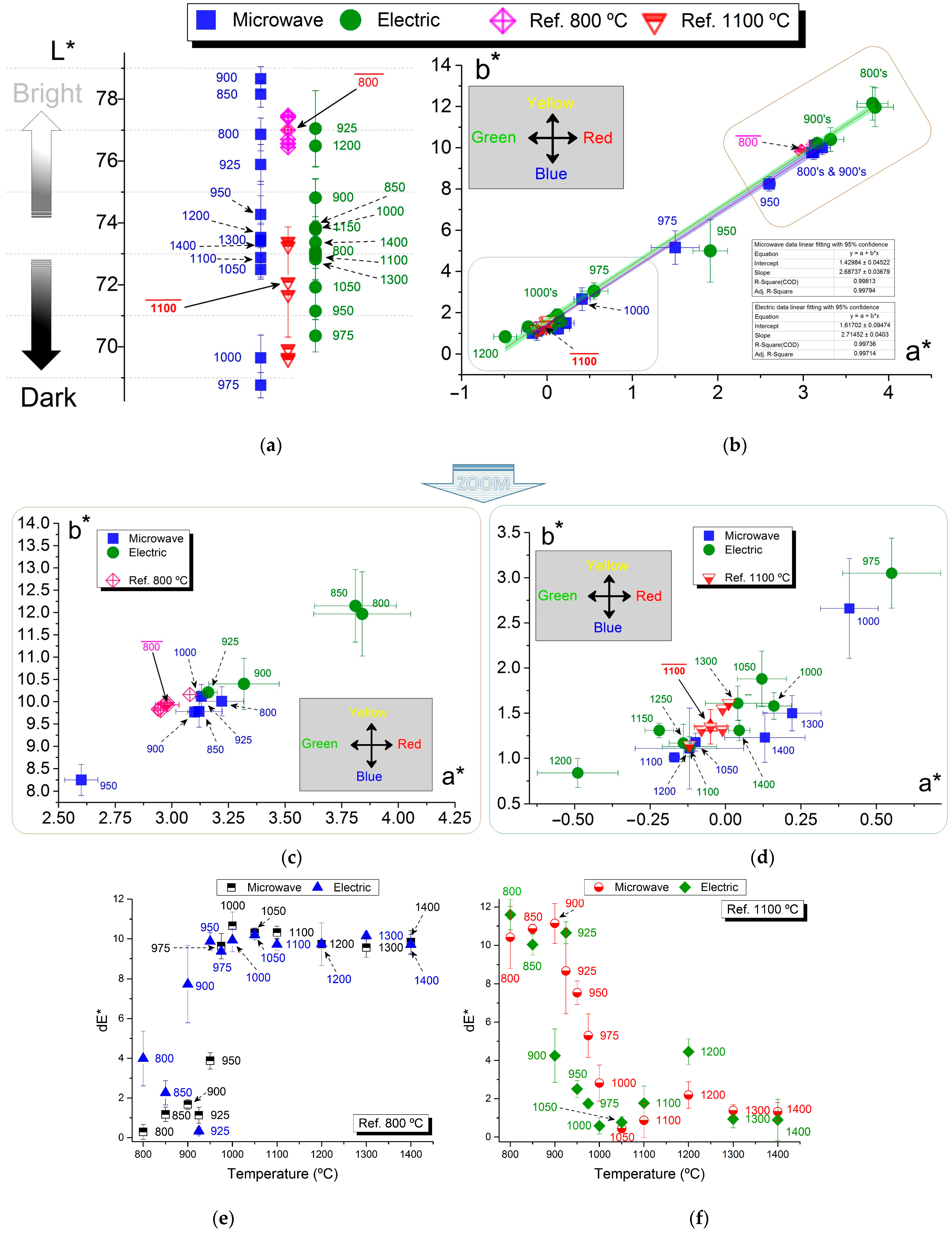
  • L* represents lightness/whiteness (0 = dark, 100 = light).
  • a* ranges from green to red (negative values indicate a shift toward green, while positive values indicate a shift toward red).
  • b* ranges from blue to yellow (negative values indicate a shift toward blue, while positive values indicate a shift toward yellow).
The color coordinate measurements were performed under a daylight illuminant (D65) and 10° observer angle, using the Konica Minolta CM700D spectrophotometer equipped with a Ø 8 mm target mask (Konica Minolta, Inc., Tokyo, Japan).
Figure 3 depicts two firing test cases. It is worth noting that no visible color differences are present in image (b), indicating a relatively good temperature homogeneity in the microwave furnace. By comparison, in [19] a temperature variation of approximately 53 °C was observed among cups fired at 1360 °C, as measured by the pyrometer. This porcelain object, which resembles a tile, has dimensions matching the effective area (25 cm × 27 cm) of the furnace base.

3. Results

As previously mentioned, several low- and high-firing decals were tested. However, only those that presented a change in color identifiable to the naked eye were used for temperature measurement tests based on the pigment’s color change.
On the other hand, tests in which there is no noticeable change in the color or brightness of the decoration confirmed that it is possible to fire decorated pieces in a microwave furnace while achieving the same aesthetic characteristics as those conventionally fired. Examples include the firing of high-fire cobalt blue, high-fire dark green, and low-fire orange, as illustrated in Figure 4.
Figure 5 presents three pieces with low-fire blue decals that were microwave fired at different temperatures and holding times, exhibiting clear differences in color and hue. When overheated, that is, heated above the optimum firing temperature, the pigment not only undergoes a color change but may also develop bubbles (clearly visible in the yellow decal in Figure 3a). Additionally, although not evident in the images, the brightness of the decal is also affected.
The image on the left, corresponding to a decal fired at 850 °C, displays a dull blue color, and the decal is easily detected by touch—the decal was not fully fused into the glaze. In contrast, the central image, fired at 910 °C, exhibits a bright blue hue. The image on the right, decal fired at 1020 °C, reveals a darker yet still bright blue color.
The low-fire blue and silver decals were selected for the L*, a*, and b* color coordinates analysis, with firings conducted in both the electric and microwave furnaces at temperatures ranging from 800 °C to 1400 °C. The firings performed in the Costa Verde gas-fired decoration kiln at 800 °C, 1100 °C, and 1180 °C were used as references. Figure 6 and Figure 7 present images of the cups’ bases, which were subjected to a third firing at various temperatures for the low-fire silver and low-fire blue decals, respectively. For the silver decal, the figures display the extreme temperatures of 800 °C and 1300 °C, along with two intermediate temperatures, of 950 °C and 1100 °C (central images). In the case of the blue decal, only one intermediate temperature, 1125 °C, is shown, as to the naked eye, it is very difficult to differentiate between them. These temperatures (samples) were selected as corresponding to points where color and hue transitions are visibly noticeable, particularly in the case of silver. For blue, the color change occurs more gradually.
Figure 8 and Figure 9 present the color coordinates for the case studies mentioned. Figure 8 presents the color coordinates of the low-fire blue-stamped decal samples fired between 800 °C and 1400 °C in the microwave and electric furnaces, along with all data (including dE* calculations) related to the gas-fired references.
Figure 9 presents the color coordinates of the low-fire silver-stamped decal samples fired between 800 °C and 1400 °C in the microwave and electric furnaces, as well as those of the gas-fired references, including dE* color difference relative to the reference samples’ color.
Based on the available data and through a visual analysis, overall, it can be observed that the stamped pieces electrically fired at 900 °C are comparable to those microwave fired at 800 °C, as well as to the reference samples fired at 800 °C in the gas-fired kiln. As the firing temperatures increase, the observed differences between the samples become progressively smaller.
Regarding lightness, Figure 8a shows an increase in the L* value with rising temperature, approaching mid-range lightness levels (L* = 50), which corresponds to the expected lightening of the blue color, as also illustrated in Figure 7. In contrast, the silver decal color tends to lose brightness with increasing temperature, as visually evident in Figure 6 and confirmed by the decrease in L* values shown in Figure 9a. An exception is observed in outliers around 950–1000 °C, deviating from this overall trend. It is worth highlighting, specifically referring to Figure 9b, the linear trend observed for the ab* pair, which tends toward the neutral (0, 0) coordinate (gray color) as the temperature increases, resulting in a faded appearance (as illustrated in Figure 6). Furthermore, both linear trends (and their corresponding data) overlap regardless of whether the samples were fired in the microwave or electric furnace, and align with the reference values obtained from gas-fired industrial kiln samples, with microwave-fired samples (both blue and silver decorated) presenting a closer piece–temperature match with those gas fired. Both linear fits present an R2 value greater than 0.997 and a notably narrow 95% confidence band. Furthermore, it is interesting to observe a noticeable shift in the data, which, in the case of the blue decal, appears as a vertical shift towards higher b* values, for temperatures between 1000 °C and 1075 °C (as illustrated in Figure 8b). This behavior is observed across both sets fired in the electric and microwave kilns. A similar pattern can be seen for the ab* pair in the case of the silver decal (Figure 9b), although occurring at slightly lower temperatures, around 950–1000 °C, as previously for L* coordinate color “outliers”. In this latter case, the shift follows the established trend line or fitting. Although these inflection points are visible, a deeper investigation into their underlying causes lies beyond the scope of the present study. Therefore, we limited ourselves to reporting and highlighting these experimental observations.
Regarding the total color difference (dE*) analysis for each case and its reference set, it is worth highlighting the consistency with previous color coordinate discussions. dE* values approached zero near the temperatures of the reference samples. For silver-colored samples, dE* is lowest at 1000 °C in electric fired samples, showing a better match to the reference gas fired (Ref.1100 °C) than the microwave fired counterpart at the same temperature.
When conducting decal firing tests, temperature data were obtained using ETH and LTH PTCR rings. Table 1 shows evidence that the rings having the minimum and maximum temperatures are in similar positions, almost independent of the firing batch/temperature.
The PTCR temperature assessment and comparison are depicted in Table 2, summarizing the average temperature, the temperature measured by the pyrometer (Tp (°C)) or setpoint temperature, the firing time (to reach the maximum temperature), the maximum temperature difference between the PTCR elements, and the difference in the average temperature relative to the setpoint temperature.
Table 3 shows the PCTR ring temperatures in decal firing tests (equivalent to those performed in microwave batches) conducted in the electric furnace and in the conventional decoration gas-fired kiln of Porcelanas da Costa Verde S.A. In this case, the setpoint temperature is given by the thermocouple (TT (°C)) installed in both electric and industrial furnaces/kilns.
As shown in [19,52], temperature variations and their history during firing differ for each piece, depending on its position in the furnace. The lower and higher temperature regions tend to appear in consistent areas. This is not exclusive to microwave furnaces, as demonstrated in Table 3, and is particularly evident in electric furnaces, tunnel gas kilns being no exception. This is well known by ceramists, and depends on several factors, including the furnace’s/kiln’s size, and the number, volume, and positioning of the pieces inside it. Moreover, in gas and electric furnaces, the placement of burners or resistance elements is a key factor. In microwave furnaces, additional effects, such as the relative positioning of the magnetrons, are key factors. Regarding the latter, although some variability was expected since each batch maintains the same number, positioning, and type of materials, and magnetron sequencing operation, this behavior is not so surprising.
It is important to note that the firing time refers to the duration until the maximum firing temperature is reached, which is the same for the (gas-fired) tunnel kiln. As mentioned in Section 2, cooling in both the electric and microwave furnaces is natural, depending only on the thermal inertia of each furnace, which is comparable and takes approximately 3 h. Moreover, regarding conventional kilns, the cooling is relatively controlled by using gas burners and cold air. Additionally, for conventional (mass-production) kilns, their use for experiments is always dependent on availability, the cycle and heat work being used, and the materials being fired at a given time.
The results presented in Table 1, Table 2 and Table 3 relate to batch tests conducted in microwave and electric furnaces with pieces decorated with low-fire blue and silver decals. The tests were performed to evaluate the temperature based on the color change of a given pigment. Therefore, the firing times were kept at approximately 90 min, the time used in decoration firing in Porcelanas da Costa Verde being only that required to reach the maximum temperature. Considering only the rings’ temperatures and comparing them with the reference (fired at 880 °C and 1180 °C), it can be seen that in about 90 min the ring temperatures fall within the normal range, regardless of the heating technology used. The temperature differences are only a few dozen degrees, with the temperatures of the rings used in the microwave furnace being generally closer to the setpoint temperature.
Figure 10 displays an image of a black decal on a white porcelain cup microwave fired at 920 °C in a 50 min heating cycle, alongside two images of saucers that were microwave fired for 43 min, followed by a soaking time of 5 min at the maximum temperature of 1180 °C, depicting intricate, colored, and detailed decal designs. Identical pieces were fired in the conventional (gas-fired) tunnel kiln, exhibiting no visual and aesthetic differences from those that were microwave fired (presented here). As expected, the diffusion of the decal into the glaze was noticeable, unlike in the electrically fired pieces, where, using identical heat work, the same aesthetic results were not reached, with the decal not fully fused into the glaze, which is easily detected by touch.

4. Discussion

The microwave firing of decorated porcelain has focused on achieving the same aesthetic results as in conventional (gas-fired) kilns while evaluating the thermal effects on pigments. Since some colors change with temperature, these transformations have been used as indicators to assess the effectiveness of microwave processing. Analysis of L*, a*, and b* color coordinates has shown that microwave-fired samples exhibit differences in color tone compared to their electrically fired counterparts. Visual analysis indicates that conventionally fired samples at 900 °C resemble microwave-fired samples at 800 °C and gas-fired samples at the same temperature. Overall, these findings align with the literature regarding the visual/optical differences between microwave and conventionally fired ceramics and regarding the microstructural, morphological, and crystallochemical/mineral phase changes or transformations, and macroscopic properties [21,23,26,27,28,29,30,31,32,33]. Microwave versus conventional firing of porcelain from Porcelanas da Costa Verde was studied in [15,20,40,43] regarding their crystallochemical, macroscopic/macrostructural (density, water absorption, energy of rupture), microstructural, and color properties and transformations occurring in the porcelain body, respectively.
The unexpected dispersion in the color analysis data presents challenges in accurately assessing the firing temperature based solely on pigment color changes. Although this does not allow an accurate temperature assessment during firing, along with a visual analysis including the reference samples, an estimated temperature offset of approximately 50 °C between microwave-fired and electrically fired samples is suggested, for both the silver and blue decals. Generally, pieces stamped and electrically fired with the same heat work used in the microwave furnace require higher temperatures to achieve color and hues or color tones comparable to those of the reference samples.
Key mineralogical changes, such as the decomposition of kaolinite, and of both mullite and glassy phases formation, influence the porcelain’s color developments. These are firing-temperature-dependent [15,39,40,41,42,53], and are expected to similarly affect decals and pigments, as presented in this study. In [54] it is demonstrated that the glaze color of standard zircon-based triaxial pigments exhibits slight variations as a function of both their chemical composition and the firing temperature.
When compared to electric firing and using equivalent heat work, microwave processing enables the completion of the mineralogical transformations and lowers the temperature threshold for specific minerals’ phase transitions, such as the decomposition of kaolinite [40,41]. Other phase/mineral transformations, including mullite formation, particularly of type-II mullite, exhibit distinct characteristics under microwave heating. In microwave-fired samples, type-II mullite crystals appear shorter than those in gas-fired reference samples but display a higher aspect ratio and increased formation [39,40,41]. Under comparable heating durations (<70 min), type-II mullite is more prevalent in microwave-fired porcelain and stoneware samples than in their electrically fired counterparts [40,41].
As the tests aimed at evaluating the temperature assessment based on pigment color change using a reference for comparison, firing times were consistently maintained at approximately 90 min, regardless of the target/setpoint temperatures. Nevertheless, 50 min firing tests in the microwave furnace demonstrated that it is possible to fast-fire porcelain products with decals without any visually perceptible differences in aesthetic quality compared to the (gas-fired) reference samples.
Regarding temperature measurement, Table 4 summarizes the advantages and disadvantages of the different sensor types that can be used in microwave porcelain furnaces. The fiber optics approach is also included for comparison purposes, although the use of this sensor is not covered in the present research. In [52], the preliminary results of porcelain firing are presented, using Bragg fibers to measure/assess the temperature in several cups positioned in different positions inside the microwave furnace. The present perspectives about temperature assessment using decal color are also considered, presenting the perspectives of its usage as a “temperature sensor”.
As demonstrated in previous studies [27,56], the successful microwave firing of painted ceramics is both feasible and effective. This heating method presents significant advantages, notably a substantial reduction in firing time, which directly contributes to lowering both economic and environmental costs. These benefits are particularly relevant when the energy used originates from genuinely renewable sources, further enhancing the process’s sustainability. Although some issues require further refinement, the present study provides strong evidence that the color change of a pigment can be used to assess the firing temperature or the thermal energy to which a ceramic piece has been exposed (the heat work). Furthermore, this study suggests that, particularly when using pigments with high firing temperature sensitivity, especially near a known temperature, this method could be used to map the temperature distribution across the entire surface of the piece. This would enable the creation of a 3D thermal map through post-firing analysis. While real-time 3D in situ monitoring is not practically feasible, this approach offers a valuable tool for assessing thermal homogeneity inside a microwave furnace, mapping it, and aiding process optimization and kiln design improvements, albeit reactively, that is, post-firing. Moreover, this methodology is not exclusive to microwave furnaces or kilns and can be used with any type of furnace and heating technology. In a way, it is comparable to the use of PTCR rings and of a thermal camera, with the advantage that the piece’s surface is mapped and that an initial visual assessment can be made immediately, and the thermal record remains permanently imprinted on the piece.

5. Conclusions

The present research focuses on the microwave firing of decorated porcelain, aiming to achieve the same aesthetic results as in conventional kilns. Since some decals’ colors change with the applied heat work, they can be used as “sensors” to assess the effectiveness of microwave temperature processing. Analysis of L*, a*, and b* color coordinates shows that microwave-fired samples exhibit differences in color tone compared to electrically fired counterparts. Moreover, samples electrically fired at 900 °C resemble microwave-fired and gas-fired samples at (the lower temperature of) 800 °C. This aligns with findings reported in the literature regarding morphological, microstructural, and macrostructural differences between microwave and conventionally fired ceramics.
Conventional heating methods using gas-fired kilns provide well-established results, but emerging technologies such as microwave processing offer significant advantages in terms of the required time, energy, energy efficiency, and improved material properties. Although challenges remain, particularly in accurately assessing the firing temperature, and more particularly the energy exposure of different and individual pieces inside the microwave furnace, this research demonstrates that microwave fired decorated porcelain can achieve the quality of conventionally fired pieces, with faster heat work and reduced energy consumption. An alternative approach is investigated and presented for evaluating, assessing, and mapping the temperature of a piece after firing, specifically its surface temperature, based on the decal color analysis.

Author Contributions

Conceptualization, T.S.; methodology, T.S.; software, T.S.; validation, T.S., L.H., V.A.F.C. and L.C.C.; formal analysis, T.S., L.H., V.A.F.C. and L.C.C.; investigation, T.S.; resources, T.S., L.H., V.A.F.C. and L.C.C.; data curation, T.S.; writing—original draft preparation, T.S.; writing—review and editing, T.S., L.H., V.A.F.C. and L.C.C.; visualization, T.S., L.H., V.A.F.C. and L.C.C.; supervision, T.S., V.A.F.C. and L.C.C.; project administration, T.S., V.A.F.C. and L.C.C.; funding acquisition, T.S., L.H., V.A.F.C. and L.C.C. All authors have read and agreed to the published version of the manuscript.

Funding

This research received no external funding.

Data Availability Statement

The raw data supporting the conclusions of this article will be made available by the authors on request.

Acknowledgments

The authors express their sincere thanks to Jorge Marinheiro, and to the entourage of the decoration section, from Porcelanas da Costa Verde S.A., 3840-385 zona industrial de Vagos, Aveiro, Portugal, for all their help, contributions and donations of some materials used for the experiments, technical support, and allowing the development of reference firing tests in the company’s decorative kiln. Acknowledgement is also due to Acácio Moreira, former worker of Vista Alegre Atlantis S.A. and Porcelanas da Costa Verde S.A., for his help, donations of some materials used for the experiments, technical support, and specially the design of some decals used in the work. V. A. F. Costa acknowledges the support of the project UID 00481 Centre for Mechanical Technology and Automation (TEMA).

Conflicts of Interest

The authors declare no conflicts of interest.

Abbreviations

The following abbreviations are used in this manuscript:
PTCRProcess Temperature Control Ring
RFBGRegenerated Bragg fiber
EMFElectromagnetic field
SiCSilicon carbide
TP Temperature measured by the pyrometer (microwave-related)
TT Temperature measured by the thermocouple(s) (electric- and gas-related)

References

  1. António Tomás da, F. Tecnologia Do Processamento Cerâmico; Universidade Aberta: Lisboa, Portugal, 2000; ISBN 972-674-320-6. [Google Scholar]
  2. Reed, J.S. Introduction to the Principles of Ceramic Processing; Wiley: Hoboken, NJ, USA, 1988; ISBN 047184554X. [Google Scholar]
  3. Ryan, W.; Radford, C. Whitewares Production, Testing, and Quality Control: Including Materials, Body Formulations, and Manufacturing Processes; Freer, R., Ed.; Pergamon Press: Oxford, UK, 1987; ISBN 0080349285. [Google Scholar]
  4. Costa Verde SA. Available online: https://costa-verde.com/costaverde/# (accessed on 21 May 2019).
  5. Royal Copenhagen. General Information about Porcelain-Report.
  6. Schüller, K.H. Porcelain: Ceramics Monographs–Handbook of Ceramics; Verlag Schmidt GmbH: Freiburg, Germany, 1979. [Google Scholar]
  7. Vista Alegre SA: Porcelana, Cristal Desde. 1824. Available online: https://vistaalegre.com/pt/ (accessed on 5 April 2019).
  8. Bordallo Pinheiro. Available online: https://pt.bordallopinheiro.com/ (accessed on 5 April 2019).
  9. Molinari, C.; Conte, S.; Zanelli, C.; Ardit, M.; Cruciani, G.; Dondi, M. Ceramic Pigments and Dyes beyond the Inkjet Revolution: From Technological Requirements to Constraints in Colorant Design. Ceram. Int. 2020, 46, 21839–21872. [Google Scholar] [CrossRef]
  10. Freiman, S.; Rumble, J. Current Availability of Ceramic Property Data and Future Opportunities. Am. Ceram. Soc. Bull. 2013, 92, 34–38. [Google Scholar]
  11. Tozzi, N. Glaze and Body Pigments and Stains in the Ceramic Tile Industry. Available online: https://digitalfire.com/article/glaze+and+body+pigments+and+stains+in+the+ceramic+tile+industry (accessed on 5 June 2025).
  12. Katsuki, H.; Shiraishi, A.; Pee, J.H.; Cho, W.S.; Takashi, Y.; Kubuki, S. A Relationship between Oxidation State of Iron and Color of Arita Celadon Glaze Characterized by 57Fe-Mossbauer Spectroscopy. J. Ceram. Soc. Jpn. 2014, 122, 520–522. [Google Scholar] [CrossRef]
  13. Williams, J. Reworking the Rainbow: Printing on Ceramics and Glass. Available online: https://screenprintingmag.com/reworking-the-rainbow/amp/ (accessed on 5 June 2025).
  14. Partyka, J.; Gajek, M. Effect of Firing Condition on Ceramic Glaze Colour Tonality. InterCeram Int. Ceram. Rev. 2012, 61, 270–276. [Google Scholar]
  15. Santos, T.; Hennetier, L.; Costa, V.A.F.; Costa, L.C. Microwave versus Conventional Porcelain Firing: Colour Analysis. Mater. Chem. Phys. 2022, 275, 125265. [Google Scholar] [CrossRef]
  16. FERRO GmbH Process Temperature Control Rings (PTCR), Technical Information IS05 n.d. 2019, 1–6. Available online: www.therseruk.com/ferro-rings/ (accessed on 20 June 2025).
  17. Guan, Y.; Nikawa, Y. Measurement of Temperature-Dependent Complex Permittivity for Materials Using Cylindrical Resonator under Microwave Irradiation. Electron. Commun. Japan Part II Electron. 2007, 90, 1–8. [Google Scholar] [CrossRef]
  18. Pert, E.; Carmel, Y.; Birnboim, A.; Olorunyolemi, T.; Gershon, D.; Calame, J.; Lloyd, I.K.; Wilson, O.C. Temperature Measurements during Microwave Processing: The Significance of Thermocouple Effects. J. Am. Ceram. Soc. 2001, 84, 1981–1986. [Google Scholar] [CrossRef]
  19. Santos, T.; Hennetier, L.; Costa, V.A.F.; Costa, L.C. Microwave versus Conventional Porcelain Firing: Temperature Measurement. J. Manuf. Process. 2019, 41, 92–100. [Google Scholar] [CrossRef]
  20. Santos, T.; Hennetier, L.; Costa, V.A.F.; Costa, L.C. Microwave vs Conventional Porcelain Firing: Macroscopic Properties. Int. J. Appl. Ceram. Technol. 2020, 17, 2277–2285. [Google Scholar] [CrossRef]
  21. Clark, D.E.; Sutton, W.H. Microwave Processing of Materials. Annu. Rev. Mater. Sci. 1996, 26, 299–331. [Google Scholar] [CrossRef]
  22. Janney, M.A.; Kimrey, H.D.; Kiggans, J.O. Microwave Processing of Ceramics: Guidelines Used at the Oak Ridge National Laboratory. In Microwave Processing of Materials III; Beatty, R.L., Sutton, W.H., Iskander, M.F., Eds.; Materials Research Society: Pittsburg, PA, USA, 1992; Volume 269, pp. 173–185. ISBN 1558991646. [Google Scholar] [CrossRef]
  23. Sutton, W.H. Microwave Processing of Ceramics-an Overview. In Microwave Processing of Materials III; Beatty, R.L., Sutton, W.H., Iskander, M.F., Eds.; Materials Research Society: Pittsburg, PA, USA, 1992; Volume 269, pp. 3–20. ISBN 1558991646. [Google Scholar] [CrossRef]
  24. Keyson, D.; Longo, E.; Vasconcelos, J.S.; Varela, J.A.; Éber, S.; DerMaderosian, A. Síntese e Processamento de Cerâmicas Em Forno de Microondas Doméstico. Cerâmica 2006, 52, 50–56. [Google Scholar] [CrossRef]
  25. Levinson, M.L. Method of Firing Ceramic Articles Utilizing Microwave Energy. U.S. Patent No. 3,585,258, 15 June 1971. [Google Scholar]
  26. Metaxas, A.C. Microwave Heating. Power Eng. J. 1991, 5, 237. [Google Scholar] [CrossRef]
  27. Clark, D.E.; Folz, D.C. What Is Microwave Processing? Available online: https://www.researchgate.net/publication/290488291_Introduction_What_is_Microwave_Processing (accessed on 25 December 2018).
  28. Thostenson, E.T.; Chou, T.-W. Microwave Processing: Fundamentals and Applications. Compos. Part A Appl. Sci. Manuf. 1999, 30, 1055–1071. [Google Scholar] [CrossRef]
  29. Oghbaei, M.; Mirzaee, O. Microwave versus Conventional Sintering: A Review of Fundamentals, Advantages and Applications. J. Alloys Compd. 2010, 494, 175–189. [Google Scholar] [CrossRef]
  30. Rybakov, K.I.; Olevsky, E.A.; Krikun, E.V. Microwave Sintering: Fundamentals and Modeling. J. Am. Ceram. Soc. 2013, 96, 1003–1020. [Google Scholar] [CrossRef]
  31. Mishra, R.R.; Sharma, A.K. Microwave–Material Interaction Phenomena: Heating Mechanisms, Challenges and Opportunities in Material Processing. Compos. Part A Appl. Sci. Manuf. 2016, 81, 78–97. [Google Scholar] [CrossRef]
  32. Meredith, R.J.; Metaxas, A.C. Industrial Microwave Heating; The Institution of Engineering and Technology: London, UK, 1988. [Google Scholar]
  33. Meredith, R. Engineers’ Handbook of Industrial Microwave Heating; Johns, A.T., Warne, D.F., Eds.; Institution of Electrical Engineers: London, UK, 1998; Volume 25, ISBN 0852969163. [Google Scholar]
  34. Oliveira, F.M.; Azadmanjiri, J.; Wang, X.; Yu, M.; Sofer, Z. Structure Design and Processing Strategies of MXene-Based Materials for Electromagnetic Interference Shielding. Small Methods 2023, 7, 2300112. [Google Scholar] [CrossRef]
  35. Herrero, M.A.; Kremsner, J.M.; Kappe, C.O. Nonthermal Microwave Effects Revisited: On the Importance of Internal Temperature Monitoring and Agitation in Microwave Chemistry. J. Org. Chem. 2008, 73, 36–47. [Google Scholar] [CrossRef] [PubMed]
  36. Wroe, R. Microwave-Assisted Firing of Ceramics. Power Eng. J. 1996, 10, 181–183. [Google Scholar] [CrossRef]
  37. Bao, R.; Yi, J.H.; Peng, Y.D.; Zhang, H.Z. Effects of Microwave Sintering Temperature and Soaking Time on Microstructure of WC-8Co. Trans. Nonferrous Met. Soc. China Engl. Ed. 2013, 23, 372–376. [Google Scholar] [CrossRef]
  38. Fernandes, J.P.C.; Gunnewiek, R.F.K.; Souto, P.M.; Kiminami, R.H.G.A. Monoqueima de Porcelanas Esmaltadas Em Forno de Micro-Ondas. Cerâmica 2014, 59, 545–550. [Google Scholar] [CrossRef]
  39. Lerdprom, W.; Zapata-Solvas, E.; Jayaseelan, D.D.; Borrell, A.; Salvador, M.D.; Lee, W.E. Impact of Microwave Processing on Porcelain Microstructure. Ceram. Int. 2017, 43, 13765–13771. [Google Scholar] [CrossRef]
  40. Santos, T.; Gomes, C.S.F.; Costa, V.A.F.; Costa, L.C. Microwave Versus Conventional Porcelain Firing: Greenware to Biscuit Crystallochemical Transformations. J. Manuf. Sci. Eng. 2021, 143, 121001. [Google Scholar] [CrossRef]
  41. Santos, T.; Gomes, C.S.F.; Santos, N.F.; Costa, V.A.F.; Costa, L.C. Global Insight into Microwave Stoneware Firing: Crystallochemical Transformations. Ceram. Int. 2022, 48, 21492–21501. [Google Scholar] [CrossRef]
  42. Moratal, S.; Gil-Flores, L.; Salvador, M.D.; Suarez, M.; Penaranda-Foix, F.L.; Borrell, A. Study of Colored on the Microwave Sintering Behavior of Dental Zirconia Ceramics. J. Asian Ceram. Soc. 2021, 9, 188–196. [Google Scholar] [CrossRef]
  43. Santos, T.A.C.; Costa, V.A.F.; Costa, L.M.C.M. Microstructure Analysis of Microwave and Conventionally Fired Porcelain. Fire Mater. 2023, 47, 375–385. [Google Scholar] [CrossRef]
  44. Demirel, M.G.; Tunçdemir, A.R. The Effect of Repeated Firings on the Color Change of Metal Based Ceramics Produced with Different Techniques. Necmettin Erbakan Univ. Dis Hekim. Derg. NEU Dent. J. 2023, 5, 67–74. [Google Scholar] [CrossRef]
  45. Ramos, P.A.V.; Albuquerque, D.M.S.; Pereira, J.C.F. Enhancing the Efficiency of Brown 24 Pigment Production through Continuous Microwave Heating in Conveyor Belt and Rotary Kiln Systems: A Design and Optimization Study. Energy 2024, 309, 133123. [Google Scholar] [CrossRef]
  46. García-Baños, B.; Sánchez, J.R.; Godes, J.L.; Leonelli, C.; Catalá-Civera, J.M. Evaluation of Microwave Synthesis of Ceramic Pigments Based on In Situ Dielectric Characterization. Materials 2023, 16, 2976. [Google Scholar] [CrossRef]
  47. Miguel, E.; Paulo-Redondo, G.; Carda Castelló, J.B.; Nebot-Díaz, I. Comparative Study of the Synthesis of a Red Ceramic Pigment Using Microwave Heat Treatment. Colorants 2023, 2, 518–532. [Google Scholar] [CrossRef]
  48. LG Electronics Inc. Magnetron 2M226 Model-Specifications. 2015. Available online: https://uniservice.msk.ru/docs/2M226-23TAG.pdf (accessed on 20 June 2025).
  49. C.M.I., K. Kapyrok Product Information 1.
  50. Malacara, D.; Daniel, M. Color Vision and Colorimetry: Theory and Applications; SPIE Press: Bellingham, WA, USA, 2002; ISBN 0819442283. [Google Scholar]
  51. McLaren, K. XIII—The Development of the CIE 1976 (L* A* B*) Uniform Colour Space and Colour-Difference Formula. J. Soc. Dye. Colour. 1976, 92, 338–341. [Google Scholar] [CrossRef]
  52. Pereira, D.; Santos, T.; Nogueira, R.; Costa, L.C.; Alberto, N. High Temperatures (>1000 °C) Monitoring during the Sintering Process in Microwave Oven Using RFBGs. Opt. Quantum Electron 2016, 48, 304. [Google Scholar] [CrossRef]
  53. Wiśniewska, K.; Pichór, W.; Kłosek-Wawrzyn, E. Influence of Firing Temperature on Phase Composition and Color Properties of Ceramic Tile Bodies. Materials 2021, 14, 6380. [Google Scholar] [CrossRef] [PubMed]
  54. Blonski, R.P. Higher-Chroma Zircon Colors for Glaze Applications. In Ceramic Engineering and Science Proceedings; Wachtman, J.B., Jr., Ed.; John Wiley & Sons, Inc.: Hoboken, NJ, USA, 1994; pp. 266–280. [Google Scholar] [CrossRef]
  55. Durka, T.; Stefanidis, G.D.; Van Gerven, T.; Stankiewicz, A. On the Accuracy and Reproducibility of Fiber Optic (FO) and Infrared (IR) Temperature Measurements of Solid Materials in Microwave Applications. Meas. Sci. Technol. 2010, 21, 1–8. [Google Scholar] [CrossRef]
  56. Santos, T.; Ramani, M.; Devesa, S.; Batista, C.; Franco, M.; Duarte, I.; Costa, L.; Ferreira, N.; Alves, N.; Pascoal-Faria, P. A 3D-Printed Ceramics Innovative Firing Technique: A Numerical and Experimental Study. Materials 2023, 16, 6236. [Google Scholar] [CrossRef]
Figure 1. Schematic illustration of the three main types of porcelain decoration.
Jmmp 09 00213 g001
Figure 2. Microwave furnace: (a) exterior of the furnace; (b) interior of the furnace, highlighting the thermocouple and the opening/window that allows the pyrometer to read the temperature of the central piece near the door.
Jmmp 09 00213 g002
Figure 3. Examples of two case studies: (a) low-fire yellow, light-red, dark-red, and violet decals stamped in a white porcelain coffee cup; (b,c) high-fire red decal on a kind of porcelain tile, cut from a larger piece for this specific test. In (b), the reflection of one of the authors capturing the image is visible, emphasizing the piece’s gloss and the decal’s diffusion into the glaze. In (c), the image was taken at an angle to minimize reflections, showcasing the high decal’s homogeneity after firing.
Jmmp 09 00213 g003
Figure 4. Illustration of three high-fire decals in porcelain cups microwave fired at 1200 °C in 90 min: (a) cobalt blue; (b) dark-green; (c) orange.
Jmmp 09 00213 g004
Figure 5. Low-fire blue decal pieces microwave fired at (a) 850 °C, plus a soaking (or dwelling time) of 10 min; (b) 910 °C, plus a soaking time of 6 min; and (c) 1020 °C without soaking time. The change in color and gloss with the third-fire temperature is evident. Photos are presented both with (above) and without (below) the camera flash.
Jmmp 09 00213 g005
Figure 6. Photographs of low-fire silver pigment fired at (a) 800 °C; (b) 950 °C; (c) 1100 °C; and (d) 1300 °C. Although the images do not display the true colors, they illustrate the intended effect: the color changes with the firing temperature. Photos are presented both with (below) and without (above) the camera flash.
Jmmp 09 00213 g006
Figure 7. Photographs of low-fire blue pigment fired at (a) 800 °C; (b) 1125 °C; and (c) 1300 °C. Although the images do not display the true colors, they illustrate the intended effect: the color changes with the firing temperature. Photos are presented both with (below) and without (above) the camera flash.
Jmmp 09 00213 g007
Figure 8. Color coordinates of the low-fire blue-stamped decal samples fired between 800 °C and 1400 °C in the microwave and electric furnaces: (a) L* coordinate; (b) a* and b* coordinates; (ce) are the dE* color difference, relative to all reference colors. Both figures include reference samples fired in the gas kiln at 800 °C, 1100 °C, and 1180 °C.
Jmmp 09 00213 g008
Figure 9. Color coordinates of the low-fire silver-stamped decal samples fired between 800 °C and 1400 °C in the microwave and electric furnaces: (a) L* coordinate; (b) a* and b* coordinates; (c) and (d) a* and b* coordinates of the areas highlighted in (b); and (e,f) the dE* color difference relative to the color of both references (800 °C and 1100 °C). All figures include data from reference samples fired in the gas kiln at 800 °C and 1100 °C.
Jmmp 09 00213 g009
Figure 10. Microwave-fired samples in white porcelain: (a) black decal fired at 920 °C for a 50 min heating cycle; (b,c) colored and detailed decals fired for 43 min, plus a soaking time of 5 min at the maximum temperature of 1180 °C. Photos are presented with the camera flash.
Jmmp 09 00213 g010
Table 1. Rings’ temperature (PTCR: ETH and LTH rings families) in microwave firing batches: Part 1.
Batch Firing TestsPTCR’s Position Inside the Microwave Furnace
123456789101112
ETH-M1886877887888894906895906893900891881
ETH-M2-938----944-----
ETH-M39899939969951003104710061035103710301006989
ETH-M410991098error * 1083errorerror1100errorerrorerrorerrorerror
LTH-M1116311621171116411711177116911821174117111691166
The green and red background color indicate the position of the minimum and maximum PTCR temperatures inside the microwave furnace. * error: the temperature was too high for the ETH ring family at the pyrometer temperature setpoint of 1100 °C.
Table 2. Rings’ temperature (PTCR: ETH and LTH rings families) in microwave firing batches: Part 2.
Batch Firing TestTp (°C)Time (min)Average PTCR (°C)ΔT1 (°C)ΔT2 (°C)
ETH-M190091892258
ETH-M295092941-9
ETH-M3100085101158-11
ETH-M41100921095-5
LTH-M112009911702030
ΔT1 is the maximum temperature difference relative to the average temperature. ΔT2 is the difference between the average temperature and the setpoint temperature in the microwave furnace.
Table 3. Ring temperature (PTCR: ETH and LTH rings families) evaluated in electrically fired batches and in the conventional (gas-fired) decoration furnace of Porcelanas da Costa Verde S.A. (gray cells).
PTCR Temperature and Position in the Electric Furnace
Batch Firing TestTT (°C)Time (min)1° PTCR (°C)2° PTCR (°C)3° PTCR (°C)Average PTCR (°C)ΔT1 (°C)ΔT2 (°C)
ETH-E190085873864-869531
ETH-E295088931909-9211029
ETH-E31000919839789589731527
ETH-E41050951047----3
LTH-E11050891043----7
ETH-E51100901087108610791084516
LTH-E211009210831106101010635637
LTH-E312009111711171-1171029
LTH-E41250931212----38
ETH-Ref.1 88090<837 43
LTH-Ref.1 11809011451143-1144136
ΔT1 is the maximum temperature difference relative to the average temperature. ΔT2 is the difference between the average temperature and the setpoint temperature in the electric furnace. Results evaluated in the Costa Verde (gas-fired) decoration kiln. The rings from the ETH family have a lower operational/working temperature limit of 850 °C. Through an extrapolation exercise, a value of 837 °C was obtained when the temperature measured by the thermocouple in the gas furnace reached 880 °C.
Table 4. Advantages and disadvantages of the different temperature sensors considered [19].
Sensor TypeThermocouplePyrometerPTCRRFBGsDecal Color
Ease of handlingYesYesYesNo *Yes
Contact measurementBoth ɸNoBoth ɸBoth ɸYes
PrecisionYesYesYes YesYes
Accuracy+/− ɸYes ΨYes +/− ɸYes
Mapping capabilityNoNoYesYesYes
FlexibilityNoNoYesYes *Yes
EMF interferenceYesNoNo No No
Temporal delay in measurementYesNoYes ƧNoYes
Measurement areaSmall
(at the thermocouple tip)
Small
(only at the sample surface spot area)
Relatively volumetric
(size of the PTCR)
Area/length of the FBG recording All surface
* Very fragile sensors, difficult to handle and install [55]. ɸ For more accurate readings, the sensor should be placed as close as possible. While they are typically positioned some distance from the fired object, they can also be placed in direct contact with or embedded within the object. In the PTCR case, it is positioned inside (if possible) or very close/in contact with the object. The rings are very sensitive to the thermal history (temperature, residence time, and heating and cooling rates). To be as close to the actual temperature as possible, it is necessary to perform a calibration whenever any of these parameters changes. Ψ Since emissivity varies with the characteristics of the material and depends on temperature, heating different materials always implies calibration. Depending on the dielectric properties of the rings and RFBGs, they can interfere with the electromagnetic field (EMF) by absorbing some microwave radiation. Ƨ The ring alone does not allow real-time temperature reading; only after firing is it possible to measure the thermal energy to which it was subjected, and from there, estimate the temperature. Depending on the number of recordings on the same fiber, it can be more or less volumetric.
Disclaimer/Publisher’s Note: The statements, opinions and data contained in all publications are solely those of the individual author(s) and contributor(s) and not of MDPI and/or the editor(s). MDPI and/or the editor(s) disclaim responsibility for any injury to people or property resulting from any ideas, methods, instructions or products referred to in the content.

