Article

Evaluation of Conditions for Self-Healing of Additively Manufactured Polymer Composites with Continuous Carbon Fiber Reinforcement

by
Marius Rimašauskas
*,
Tomas Kuncius
,
Rūta Rimašauskienė
and
Tomas Simokaitis
Department of Production Engineering, Kaunas University of Technology, Studentu st. 56, LT-51424 Kaunas, Lithuania
*
Author to whom correspondence should be addressed.
J. Manuf. Mater. Process. 2025, 9(6), 179; https://doi.org/10.3390/jmmp9060179
Submission received: 17 April 2025 / Revised: 18 May 2025 / Accepted: 21 May 2025 / Published: 28 May 2025

Abstract

Additive manufacturing (AM) is one of the most frequently used technologies to produce complex configuration products. Moreover, AM is very well known as a technology which is characterized by a low amount of generated waste and the potential to be called zero-waste technology. As is known, there are seven main groups of technologies described in the ISO/ASTM 52900 standard that allow the use of very different materials from polymers to metals, ceramics, and composites. However, the increased utilization of additively manufactured composites for different applications requires a deeper analysis of production processes and materials’ characteristics. Various AM technologies can be used to produce complex composite structures reinforced with short fibers; however, only material extrusion (MEX)-based technology is used for the production of composites reinforced with continuous fibers (CFs). At this time, five different methods exist to produce CF-reinforced composite structures. This study focuses on co-extrusion with the towpreg method. Because of the complexity and layer-by-layer nature of the process, defects can occur during production, such as poor interlayer adhesion, increased porosity, insufficient impregnation, and others. To eliminate or minimize defects’ influence on mechanical properties and structural integrity of additively manufactured structures, a hypothesis was proposed involving heat treatment. Carbon fiber’s conductive properties can be used to heal the composite structures, by heating them up through the application of electric current. In this research article, an experimental evaluation of conditions for additively manufactured composites with continuous carbon fiber reinforcement for self-healing processes is presented. Mechanical testing was conducted to check the influence of heat treatment on the flexural properties of the composite samples.

Graphical Abstract

1. Introduction

Additive manufacturing is the most frequently used technique for the fabrication of high-complexity configuration products [1,2]. That technology is distinguished as a separate technology group whose main uniqueness is the production of the product by using a layer-by-layer process according to 3D model data. Moreover, contrary to traditional subtracting and forming technologies, AM does not use a workpiece, which allows one to reduce waste significantly. According to the ISO/ASTM 52900 standard [3], additive manufacturing processes can be classified into seven different groups where the production principle or material is changing. AM technologies have been known for a long time as technologies intended for the production of prototypes, usually from pure polymers. However, in today’s manufacturing environment, single and multistep processes for the production of prototypes, final parts or series of products from very different materials can be found. Polymers [4], various metals [5,6], ceramics [7], and even composite materials [8,9] can be used in additive manufacturing processes. At the same time, when new materials appear on the market or are adopted in AM processes, the areas of applications of these technologies also greatly expand. The abovementioned processes are successfully used in automotive [1,10], aerospace [7], medical [11,12], and other industries [13,14].
Carbon-fiber-reinforced polymer composites are lightweight structures which are characterized by low mass and high strength and stiffness ratio. To improve mechanical properties, polymers can be reinforced with short carbon fibers (SCFs) or continuous carbon fibers (CCFs). Various studies have shown that the reinforcement of polymer composites with short carbon fibers allows a slight increase in mechanical properties [15]. However, the reinforcement of polymers with a continuous carbon fiber tow allows one to increase mechanical properties drastically while improving the mass-to-stiffness ratio of the structure [16]. Short-carbon-fiber-reinforced composites can be made by using various additive manufacturing technologies while continuous-carbon-fiber-reinforced composites are traditionally produced only with material extrusion-based technologies. Material extrusion-based technology initially was developed to produce pure polymer parts, which is why a modification of the printing head is required, and the preparation of a continuous carbon fiber tow is needed to produce CCF-reinforced composites [17]. There are five main methods to embed a carbon fiber tow into the polymer matrix: in situ impregnation, co-extrusion with towpreg, towpreg extrusion, in situ consolidation, and inline impregnation. Regardless of the chosen method, the produced composite structures have some minor defects (internal porosity, surface roughness) due to the nature of the material extrusion process. On the other hand, the number of air voids can be decreased by selecting optimal production parameters like the printing layer height and printing line width [18].
Over the past years, very significant interest has been seen in additively manufactured composites and their applications; therefore, the importance of mechanical properties’ improvement and self-healing is increasing too. One of the most common defects of composites is delamination, which occurs due to various reasons, such as bad adhesion between layers or bad adhesion between the matrix and reinforcement material. This is even more important in additive manufacturing, where structures are made using a layer-by-layer method. To improve interlayer adhesion, production properties can be changed [19] or additional chemical or thermal treatment of the structure can be applied. In the additive manufacturing of CCF-reinforced composites, a continuous carbon fiber is used as reinforcement material because of its light weight and superior mechanical properties [20,21]; however, carbon fibers have not only excellent mechanical properties but good electrical conductivity characteristics and could create a positive thermal effect on polymeric part properties, i.e., reduce micropores and composite matrix cracks [22,23]. Some self-healing composites or structures are designed to repair damage autonomously [24], while the healing of materials which is triggered externally is called non-autonomic self-healing process [23]. The healing process can be triggered by using different effects such as UV light or elevated temperature [25]. The self-healing of additively manufactured composite structures is particularly important because during the manufacturing process several defects could occur, such as poor interlayer adhesion and higher air void content. Moreover, for all composites used in high-performance applications, it is very important to inexpensively, efficiently, and sustainably prevent and restore structural integrity when microcracks appear in the printed structure. In the research literature, two of the most common self-healing processes using heating and heating with additional pressure can be found [26,27]. Such methods are used for additively manufactured polymeric composite samples reinforced with continuous carbon fibers. The main problem of these methods is that composite structures must be placed in an oven, and most of the time, for high-performance composite parts, it is impossible because of the size or complicated assembly. The proposed method uses carbon fibers’ conductivity properties to heat up the structure, which should eliminate these problems. Therefore, a hypothesis based on a heat treatment using carbon fibers is proposed, which should help to eliminate or minimize the number of defects and their influence on the mechanical properties and structural integrity of additively manufactured structures.
In this research work, additively manufactured composites were tested. The main aim of the research was to develop and evaluate conditions for the self-healing process in additive manufacturing of composite structures reinforced with continues carbon fibers. Finally, mechanical testing of the composite structures before heat treatment and after heat treatment was performed to validate the developed method.

2. Materials and Methods
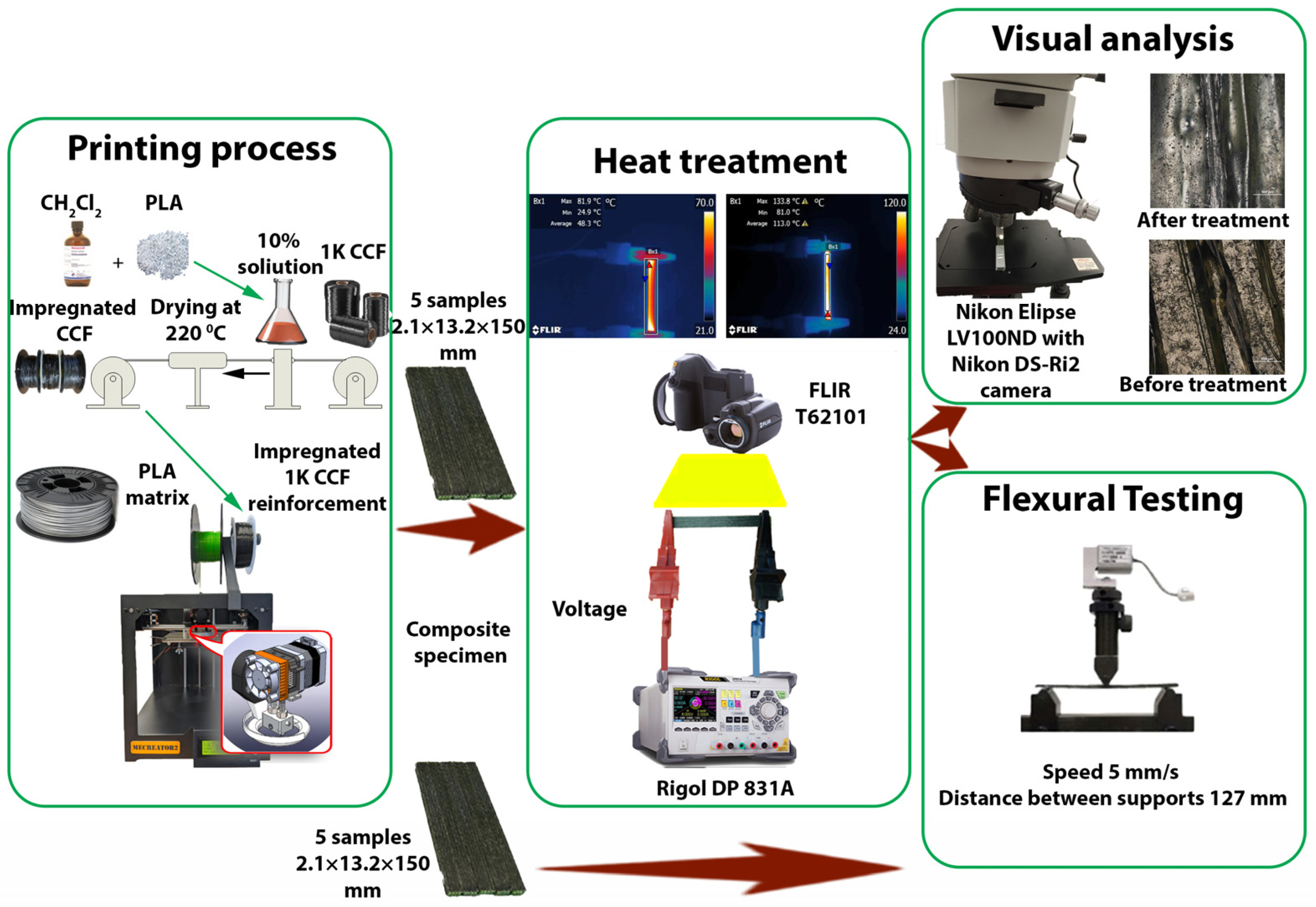
2.1. Materials

In this research, polymer composites reinforced with a continuous carbon fiber tow was used. As a reinforcement material, Toray’s T300-1000 (Toray, Lacq, France) carbon fiber tow, which consists of 1000 filaments, was used. The diameter of each separate fiber was 7 µm. The main mechanical properties such as tensile strength, tensile modulus, elongation, linear density, and density were found in material data sheets from the producer and were 3530 MPa, 30 GPa, 1.5%, 66g/1000m, 1.76 g/cm3, respectively. As a matrix material, a commercially available thermoplastic PolyLite PLA (Polymaker, Changshu, China) filament of 1.75 mm diameter was used. The main mechanical properties such as tensile strength, Young’s modulus, density were obtained from the data sheet of the material and were 52.3 MPa, 3.4 GPa and 1.17 g/cm3, respectively. More mechanical properties are provided in Table 1. It is important to mention that the production of composites by using material extrusion is a complicated process because two different materials with completely different mechanical properties have to be fed into the printing head. Moreover, another challenge is related to the compatibility of materials; they should be consolidated to make a strong bond between the reinforcement and the matrix. To feed the CCF tow more easily, additional impregnation of the carbon fiber tow was used. Before the impregnation process, PLA pellets 3D850 (NatureWorks, Blair, NE, USA) were used to prepare the impregnation solution. The pellets were dissolved using dichloromethane CH2Cl2 (Eurochemicals, Kuprioniškės, Lithuania) to obtain the optimal solution for impregnation. PLA pellets were completely dissolved using magnetic stirring equipment, the Hei-Plate (Heidolph, Schwabach, Germany), without additional heating. Finally, the CCF tow was impregnated with 10% wt. solution, dried in a heating chamber at 220 °C, and wound onto a spool at 30 rpm. The impregnation process allowed us to make the printing process easier; moreover, it allowed us to upgrade the mechanical properties of the composite structures by improving the adhesion between the matrix and reinforcement materials [28].

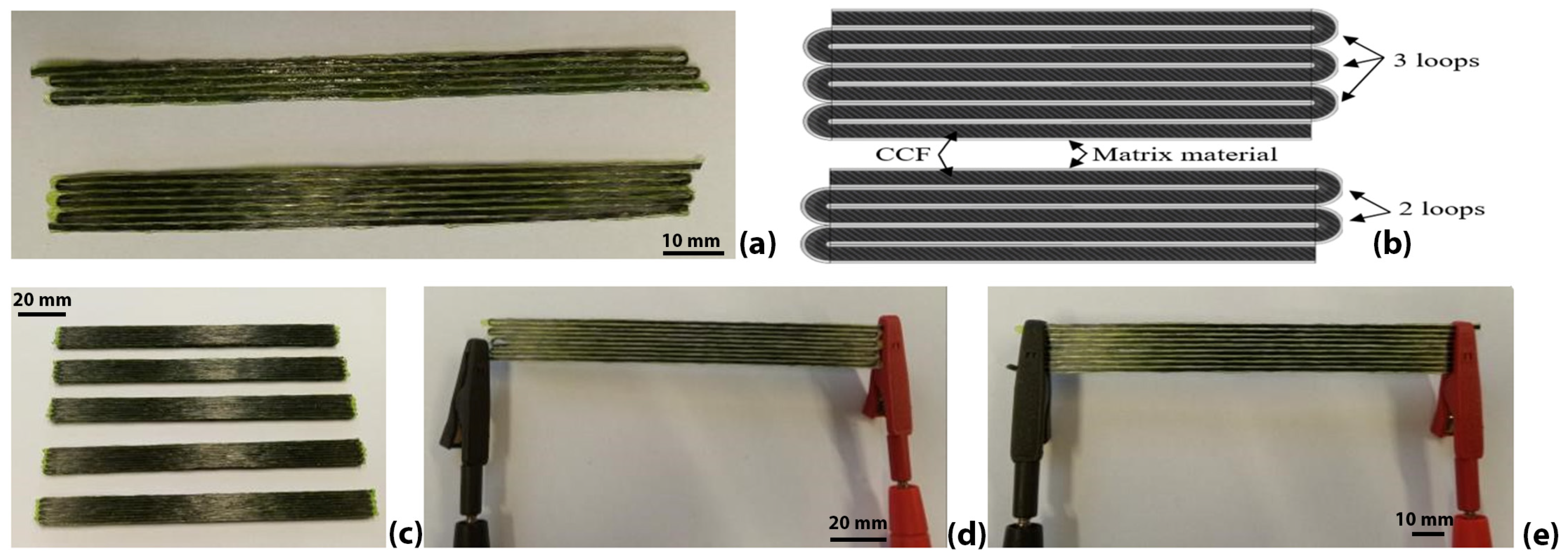
2.2. Additive Manufacturing of Composite Samples

One of the main challenges for printing composite structures reinforced with CCF by using a material extrusion process is the lack of proper equipment and knowledge. However, the simplicity and flexibility of MEX technology as well as the high level of modifications allow one to print the CCF composites after some modifications made to the standard extrusion head. In this research, co-extrusion with the towpreg method was selected and used for the production of composites. This method requires the printing head to have two inputs, one for the reinforcement material and another for the matrix material, and one output which is dedicated for composite material extrusion. A new printing head was developed and assembled with the material extrusion-based machine MeCreator 2 (Geeetech, Shenzhen, China); however, the developed process and extrusion head can be easily adapted for any other material extrusion device with open-source software. The reinforcement material underwent two impregnations during this process: primary impregnation was performed only for CCF and later, during the production process, secondary impregnation was carried out in the extrusion head where the matrix material was melted and mixed with the continuous carbon fiber tow. After mixing both materials, they formed a strong bond and were then extruded on the printing bed according to the predefined toolpath. All the additively manufactured specimens had the same 0° unidirectional layer orientation. Other printing parameters are presented in Table 2. First, specimens were designed with the help of the Solidworks 2024 (Dassault Systems, Waltham, MA, USA) 3D CAD system; later, the prepared stl files were processed with Simplify3D 5.1 (Simplify3D, Cincinnati, OH, USA) software, which allowed the final preparation of specimens for the material extrusion process and the generation of the machine control program. The main process parameters which significantly influence the quality of the printed structure are layer height and line width; in this study, these values were 0.3 and 1.2 mm, respectively. It is worth mentioning that all samples were printed with the same printing parameters and the same materials. The whole experimental setup, including impregnation of CCF, additive manufacturing of the samples, heat treatment, and mechanical properties testing, is presented in Figure 1.
As is seen from the figure, the process can be divided into three stages: first, the CCF tow was prepared, and composite samples were printed. In the second stage, a heat treatment process was used, and results were analyzed, while in the third stage, mechanical testing and visual analysis were performed.

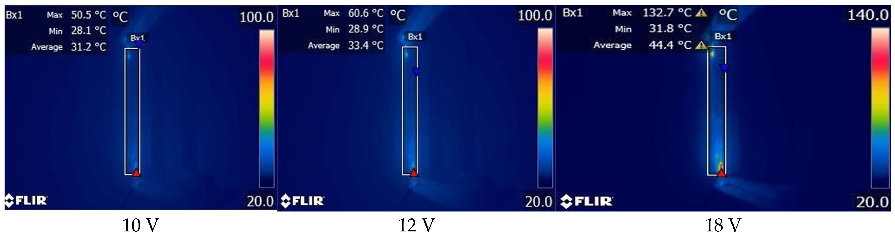
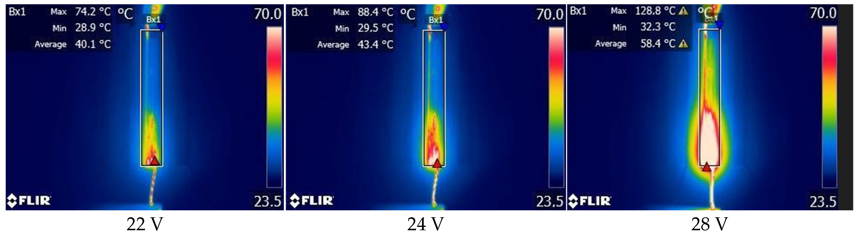
2.3. Heat Treatment Process

As mentioned before, carbon fiber is a conductive material. In this study, where composite structures were reinforced with a continuous carbon fiber, the reinforcement material was also used as a heating element. The evaluation of heating properties is important to determine the composite material’s behavior at elevated temperatures. Furthermore, the assessment of the heating impact may assist in determining whether heating may be used for the non-autonomic self-healing of the composite structure. Since thermoplastics are widely used in industry and can be easily melted, this research focused on additively manufactured composites where polylactide (PLA) was used as a matrix material. It is important to analyze whether any heating process (by using the carbon fiber as a conductor) may assist in filling the internal micro-pores generated during the technological process used in production. On the other hand, another important question should be answered with this research: whether the heating process may be used in general for improving the mechanical characteristics and quality of additively manufactured composites. In the beginning, two types of samples using the T300–1000 carbon fiber were printed for the initial examination (Figure 2a). In our case, tested samples were made using one 0.3 mm thickness single layer with a length of 100 mm; however, the widths of the samples were 6 mm and 8.4 mm for 2-and 3-loop samples, respectively (Figure 2b). After experimentations with material behavior under different elevated temperatures, another group of samples was printed (Figure 2c). In total, 10 samples were prepared, and flexural properties were tested by using a 3-point bending test. Samples for flexural tests had the following parameters: a 1.2 mm line width, 0.3 mm layer height, 2.1 mm thickness of the structure, and a 13.2 mm width and 150 mm sample length. The samples were designed, and flexural testing was conducted according to ASTM D7264 standard [28] recommendations and requirements. Flexural testing was selected to evaluate self-healing capabilities using heat treatment, because at unidirectional composites, matrix-related failures, such as microcracks, delamination, interfacial debonding, are most common under flexural load. Also, the flexural test simulated two types of deformations, compression at the top and tension from the bottom of the specimen, which let us introduce two loads during a single test.
Since printing was carried out continuously with the embedded continuous carbon fiber reinforcement in the composite structure, it was decided to use the carbon fiber as heating element by connecting electrical contacts at the beginning and the end of the CCF tow (Figure 2d). Moreover, later experiments were repeated with electrical contacts directly connected to the sample surfaces (Figure 2e). For measuring temperature changes in the samples, the thermal imaging camera T420 (Flir, Wilsonwille, OR, USA) was used. The programmable direct current power supply DP831A (Rigol, Suzhou, China) was used to initiate the heating process. To verify the assumption of how the heating process affected the mechanical characteristics of the printed samples, flexural tests were performed for heat-treated and non-heat-treated additively manufactured composite samples (Figure 2c). A universal testing machine H25KT (Tinius Olsen Ltd., Redhill, UK) equipped with an HTE-1000N load cell was used for the tests. During mechanical testing two supports and one midway load nose each of a 10 mm in diameter were used while the span length was 127 mm. The test was performed by using a crosshead speed of 5mm/min. For the data acquisition, Tinius Olsen Horizon software v10.3.0.0 was used to collect force and displacement results. After the experiments, flexural stress was calculated by using the following equation:
σ = 3 P L 2 b h 2
where σ—stress at the outer surface at mid-span, MPa; P—applied force, N; L—support span length, mm; b—width of sample, mm; h—thickness of sample, mm. Meanwhile the strain value which occurs at mid-span was calculated by the formula:
ϵ = 6 δ h L 2
where ε—maximum strain at the outer surface; δ—mid-span deflection, mm; L—support span length, mm; h—thickness of sample, mm.
A visual analysis was performed by using the optical microscope LV100ND (Nikon, Tokyo, Japan) equipped with the ultra-high-resolution 16.25-megapixel color camera DS-Ri2, while data analysis was conducted with the NIS Elements software 6.10.01.

3. Results and Discussions

The experimental measurements consisted of the following: with a voltage increase every 2 V, a break of 1 min was taken to wait for the even distribution of the temperature in the sample, and measurements of the maximum and average temperature were collected (Figure 3). The first sample to measure was the sample with two loops (with contacts connected directly to the carbon fiber tow ends (Figure 2d), with the measurement results thus obtained presented in Figure 3.
The average temperature was measured in the designated area where the sample was placed; it is worth mentioning that area was not changed during all the experiments. The thermal images showed an extremely irregular heating of the sample, i.e., maximum temperature at the contacts and slower heating of the central part of the sample. It could be seen that when voltage reached 18V, the temperature at the sample ends increased up to 132.7 °C, while the average temperature reached only 44.4 °C, which indicated a nonuniform heating of the composite structure. To assess the impact of the reinforcing material CCF tow’s length on the temperature changes in the sample, analogous experiments were conducted on three-loop samples (Figure 2d). The results obtained for the sample with three loops, with voltage changes and of the observed temperature variations, are shown in Figure 4. The images showed an extremely irregular heating of the sample, which depended on the connection of the contact in a particular place. On the other hand, reaching significant temperatures, i.e., glass transition temperature or even melting point, was possible by heating the continuous-carbon-fiber-reinforced composites. However, the results clearly showed that the selected heating procedure was not reliable and could not be used, i.e., contacts could not be connected to the beginning and the end of the same carbon fiber tow. It can be thus concluded that proper selection of the electrical contact place and area may lead to better results.
To check this assumption, the samples of several layers according to the standard test requirements were printed. In that case, the same T300–1000 carbon fiber tow was also used. The sample of such type was printed using the following parameters: a 1.2 mm space between the lines, a 0.3 mm layer thickness, a sample height of 2.1 mm, a sample width of 9.6 mm, and a sample length of 125 mm. The voltage for such types of samples was supplied directly to the sample ends (Figure 2e). The experiment aimed at the steady increase in the temperature throughout the entire sample surface. The results of such sample being heated by an evenly increasing voltage with 1 min breaks to ensure stable heating are provided in Figure 5a. Thermal images show that heating was more uniform; however, in that case, the notable impact of the contact quality between the composite material and electrical contacts was also present. It could be seen that the left part of the sample was subject to more rapid heating, and it reached a higher temperature; therefore, it could be concluded that the right part of the sample had insufficient contact between the terminal and the composite material. Therefore, it can be stated that uniformly pressing the electrical contacts with more force and cleaning the thermoplastic material from the sample ends made the distribution of temperature more even (Figure 5b).
When voltage reached 6V, the maximum temperature increased to 89.1 degrees, whereas the average temperature in the measured area increased to 64 degrees (Figure 5b). The results and the comparison of Figure 5a (6 V) and Figure 5b (6 V) show that the higher quality and stability of a contact gave a more even distribution of the temperature throughout the sample. It can be stated that the heating of the CCF reinforced composite structures can be controlled by using CCF as a heating element. At this point, notice should be taken of the average temperature in the measured area. Pressing the terminals with more force and thus obtaining better contact with the reinforcing material (carbon fiber tow) gave a significantly higher average temperature in the measured area compared to the first case (Figure 3). However, more importantly, the preparation of the contact area of the sample and ensuring even contact allowed us to obtain a more uniform heating of the entire composite structure.
Nevertheless, the most important part of this test was to determine whether the heating process may be used for the secondary melting of thermoplastics and for filling micro-gaps in the printed composite. To check this assumption, flexural strength tests were conducted on the samples. Five samples were taken for each part of the experiment. First, non-heat-treated samples were tested, and flexural stress was calculated. The second group of samples was heated to 130 °C for 30 min. The results obtained are presented in Figure 6. The test results showed the positive impact of temperature on the flexural strength of composite samples. The average flexural strength of the non-heat-treated samples was 202.7 MPa while after the heat treatment, flexural strength increased to 236.1 MPa. After the calculation of the statistical data, the results were found to be reliable because standard deviation was 18.8 MPa and 13.4 MPa, while the variation coefficient was 8.9% and 5.7% for non-heat-treated and heat-treated samples, respectively.
The assessment of the heating impact on mechanical properties suggested that such impact existed, because flexural strength increased. Very similar results were observed by Zhi-bo Pan et al., where additively manufactured CCF-reinforced flexural specimens were heat-treated at 180 °C, and flexural stress increased by 25 MPa from 60 to 85 MPa [26]. Meanwhile, Michael Handwerker et al. performed a heat treatment with additional pressures of 1 MPa and 3MPa and the tensile strength increased from 29 to 55 MPa [27]. The literature findings and our results reveal that heat treatment enhances the interlaminar properties of the composites, leading to increased maximum load capacities and improved resistance to deformation. The mechanical properties mainly increase by eliminating and minimizing printing defects such as air voids’ volume and uneven interlayer adhesion. Very similar experiments based on three-point bending test were performed by other researchers. Although composites were used, their composition was different, as the material consisted of a polystyrene shape-memory polymer with copolyester thermoplastic particles. Samples with damage and after the healing process showed decreased bending force and ductility [29]. In that article, research was conducted with pre-damaged samples while in our case, we dealt with the defects that occurred during the production process. Other research, where carbon-fiber-reinforced composites were healed with healing agents, showed a clear trend that healing efficiency improved with the increased concentration of carbon nanotubes (CNTs) [30].
Additionally, CNTs can be used as an additive to improve electrical contact, which is very important for our proposed method.
After the initial testing, it can be stated that carbon fiber tow is a good conductor of electricity and may be used to reduce the number of the sample’s micro-pores as well as improve the strength properties of the composite. This field requires a broader analysis; however, the initial results suggest that this method may be applied for self-healing applications. As mentioned before, several samples were visually tested before and after the heat treatment process with the help of an optical microscope. In Figure 7, the bottom side of the sample is presented before and after the heat treatment process. Before heat treatment, there is a clearly visible boundary between the matrix and reinforcement material, while after the heat treatment, the carbon fiber tow is fully covered with molten thermoplastic material. Moreover, it is seen that the morphology of the surface changed during the process; for example, in the sample before heating, flat zones made from thermoplastic and small grooves filled with CCF were visible. Meanwhile, after the heating process, the surface became more even, because small grooves were filled with molten thermoplastic.

4. Conclusions

The evaluation of polymer composite structures reinforced with continued carbon fibers suggests that the heating process with the use of carbon fiber tow as a conductor is possible, similar to the self-healing of thermoplastics reinforced with continuous carbon fiber. However, the necessity of a broader analysis should be emphasized to further evaluate the importance and influence of the contacts and the pressing force between electrical contacts and the composite structure. However, the tests determined that when controlling the voltage, melting thermoplastics and improving the mechanical properties of composites were possible. The results obtained showed that the flexural strength of non-heat-treated samples was 202.7 MPa, while after the heat treatment, the flexural strength reached 236.1 MPa. The increase in flexural strength was about 16 percent, but it should be emphasized that the heating was performed with a temperature of 130 °C for 30 min; therefore, to increase properties more, higher temperatures and longer heating duration should be considered. The mechanical test results showed a slight increase in flexural strength; however, more importantly, the standard deviation was lower after the heat treatment process. This proves that the improved results were most likely caused by the minimization of air voids and improved interlayer adhesion. Moreover, strains in the heat-treated samples were more uniform; therefore, mechanical behavior can be more predictable. A visual analysis confirmed that the thermoplastic material could be melted with the presented heat treatment process. Moreover, surface morphology changed, therefore this method could be considered for surface roughness minimization. The proposed heat treatment method can be interesting for applications where composites are used under high loading conditions. Such applications require lightweight structural elements without internal defects and air voids. Additionally, the method does not require putting the structures in an oven and can be used without the disassembly of complicated structures. The proposed method can extend the lifespan of composites; another important aspect is the reduction in cost for the repair of the composite structures. Composite failures related to the matrix material, such as matrix cracks, delamination, and fiber–matrix debonding can be successfully fixed. It is also hoped that this method can help to reduce the content of internal air voids; however, this should be further investigated in the future.

Author Contributions

Conceptualization, M.R. and T.K.; methodology, M.R.; software, T.S.; validation, M.R., R.R. and T.K.; formal analysis, T.S.; investigation, T.S.; resources, R.R.; data curation, T.K.; writing—original draft preparation, M.R.; writing—review and editing, T.K.; visualization, T.K.; supervision, M.R. All authors have read and agreed to the published version of the manuscript.

Funding

This research received no external funding.

Data Availability Statement

Dataset available on request from the authors.

Conflicts of Interest

The authors declare no conflict of interest.

References

  1. Yi, L.; Gläßner, C.; Aurich, J.C. How to Integrate Additive Manufacturing Technologies into Manufacturing Systems Successfully: A Perspective from the Commercial Vehicle Industry. J. Manuf. Syst. 2019, 53, 195–211. [Google Scholar] [CrossRef]
  2. Niaki, M.K.; Torabi, S.A.; Nonino, F. Why Manufacturers Adopt Additive Manufacturing Technologies: The Role of Sustainability. J. Clean. Prod. 2019, 222, 381–392. [Google Scholar] [CrossRef]
  3. ISO/ASTM. ISO/ASTM 52900:2021; Additive Manufacturing—General Principles—Fundamentals and Vocabulary. International Organization for Standardization: Geneva, Switzerland, 2021.
  4. Alghamdi, S.S.; John, S.; Roy Choudhury, N.; Dutta, N.K. Additive Manufacturing of Polymer Materials: Progress, Promise and Challenges. Polymers 2021, 13, 722. [Google Scholar] [CrossRef]
  5. Blakey-Milner, B.; Gradl, P.; Snedden, G.; Brooks, M.; Pitot, J.; Lopez, E.; Leary, M.; Berto, F.; du Plessis, A. Metal Additive Manufacturing in Aerospace: A Review. Mater. Des. 2021, 209, 110008. [Google Scholar] [CrossRef]
  6. Armstrong, M.; Mehrabi, H.; Naveed, N. An Overview of Modern Metal Additive Manufacturing Technology. J. Manuf. Process. 2022, 84, 1001–1029. [Google Scholar] [CrossRef]
  7. Dadkhah, M.; Tulliani, J.; Saboori, A.; Iuliano, L. Additive Manufacturing of Ceramics: Advances, Challenges, and Outlook. J. Eur. Ceram. Soc. 2023, 43, 6635–6664. [Google Scholar] [CrossRef]
  8. Magri, A.E.; El Mabrouk, K.; Vaudreuil, S.; Touhami, M.E. Mechanical Properties of CF-Reinforced PLA Parts Manufactured by Fused Deposition Modeling. J. Thermoplast. Compos. Mater. 2021, 34, 581–595. [Google Scholar] [CrossRef]
  9. Kubota, M.; Hayakawa, K.; Todoroki, A. Effect of Build-Up Orientations and Process Parameters on the Tensile Strength of 3D Printed Short Carbon Fiber/PA-6 Composites. Polymers 2021, 13, 1–18. [Google Scholar] [CrossRef]
  10. Zhao, N.; Parthasarathy, M.; Patil, S.; Coates, D.; Myers, K.; Zhu, H.; Li, W. Direct Additive Manufacturing of Metal Parts for Automotive Applications. J. Manuf. Syst. 2023, 68, 368–375. [Google Scholar] [CrossRef]
  11. Verma, S.; Sharma, N.; Kango, S.; Sharma, S. Developments of PEEK (Polyetheretherketone) as a Biomedical Material: A Focused Review. Eur. Polym. J. 2021, 147, 110295. [Google Scholar] [CrossRef]
  12. Kang, J.; Zhang, J.; Zheng, J.; Wang, L.; Li, D.; Liu, S. 3D-Printed PEEK Implant for Mandibular Defects Repair—A New Method. J. Mech. Behav. Biomed. Mater. 2021, 116, 104335. [Google Scholar] [CrossRef] [PubMed]
  13. de Boer, J.; Lambrechts, W.; Krikke, H. Additive Manufacturing in Military and Humanitarian Missions: Advantages and Challenges in the Spare Parts Supply Chain. J. Clean. Prod. 2020, 257, 120301. [Google Scholar] [CrossRef]
  14. Bloomfield, M.; Borstrock, S. Modeclix. The Additively Manufactured Adaptable Textile. Mater. Today Commun. 2018, 16, 212–216. [Google Scholar]
  15. Ning, F.; Cong, W.; Qiu, J.; Wei, J.; Wang, S. Additive Manufacturing of Carbon Fiber Reinforced Thermoplastic Composites Using Fused Deposition Modeling. Compos. B Eng. 2015, 80, 369–378. [Google Scholar] [CrossRef]
  16. Maqsood, N.; Rimašauskas, M. Characterization of Carbon Fiber Reinforced PLA Composites Manufactured by Fused Deposition Modeling. Compos. C Open Access 2021, 4, 100112. [Google Scholar] [CrossRef]
  17. Rimašauskas, M.; Kuncius, T.; Rimašauskienė, R. Processing of Carbon Fiber for 3D Printed Continuous Composite Structures. Mater. Manuf. Process. 2019, 34, 1528–1536. [Google Scholar] [CrossRef]
  18. Rimašauskas, M.; Jasiūnienė, E.; Kuncius, T.; Rimašauskienė, R.; Cicėnas, V. Investigation of Influence of Printing Parameters on the Quality of 3D Printed Composite Structures. Compos. Struct. 2022, 281, 115061. [Google Scholar] [CrossRef]
  19. Kuncius, T.; Rimašauskas, M.; Rimašauskienė, R. Interlayer Adhesion Analysis of 3D-Printed Continuous Carbon Fibre-Reinforced Composites. Polymers 2021, 13, 1582. [Google Scholar] [CrossRef]
  20. Kabir, S.M.F.; Mathur, K.; Seyam, A.M. A Critical Review on 3D Printed Continuous Fiber-Reinforced Composites: History, Mechanism, Materials and Properties. Compos. Struct. 2020, 232, 111476. [Google Scholar] [CrossRef]
  21. van de Werken, N.; Tekinalp, H.; Khanbolouki, P.; Ozcan, S.; Williams, A.; Tehrani, M. Additively Manufactured Carbon Fiber-Reinforced Composites: State of the Art and Perspective. Addit. Manuf. 2020, 31, 100962. [Google Scholar] [CrossRef]
  22. Calderón-Villajos, R.; López, A.J.; Peponi, L.; Manzano-Santamaría, J.; Ureña, A. 3D-Printed Self-Healing Composite Polymer Reinforced with Carbon Nanotubes. Mater. Lett. 2019, 249, 91–94. [Google Scholar] [CrossRef]
  23. Kanu, N.J.; Gupta, E.; Vates, U.K.; Singh, G.K. Self-Healing Composites: A State-of-the-Art Review. Compos. A Appl. Sci. Manuf. 2019, 121, 474–486. [Google Scholar] [CrossRef]
  24. Jones, A.R.; Watkins, C.A.; White, S.R.; Sottos, N.R. Self-Healing Thermoplastic-Toughened Epoxy. Polymer 2015, 74, 254–261. [Google Scholar] [CrossRef]
  25. Vishe, N.J.; Mulani, S.B.; Roy, S. Repeatable Self-Healing of Composite’s Fatigue Delamination. Compos. Struct. 2023, 311, 116846. [Google Scholar] [CrossRef]
  26. Pan, Z.; Zhou, W.; Ma, L.H.; Liu, J. Effect of Heat Treatment on the Damage and Failure Mechanism of 3D Printed Continuous Fiber Composites Using Acoustic Emission. Fibers Polym. 2023, 24, 2117–2213. [Google Scholar] [CrossRef]
  27. Handwerker, M.; Wellnitz, J.; Marzbani, H.; Tetzlaff, U. Pressure and heat treatment of continuous fibre reinforced thermoplastics produced by fused filament fabrication. Prog. Addit. Manuf. 2023, 8, 99–116. [Google Scholar] [CrossRef]
  28. ASTM. ASTM D7264/D7264M-15; Standard Test Method for Flexural Properties of Polymer Matrix Composite Materials. ASTM International: West Conshohocken, PA, USA, 2015.
  29. Champagne, J.; Pang, S.; Li, G. Effect of confinement level and local heating on healing efficiency of self-healing particulate composites. Compos. B. Eng. 2016, 97, 344–352. [Google Scholar] [CrossRef]
  30. Wan, W.; Shen, R.; Tang, J.; Xu, Y.; Zou, X.; Gou, H. Carbon fiber reinforced composites with self-sensing and self-healing capabilities enabled by CNT-modified nanofibers. Polym. Compos. 2024, 45, 7301–7315. [Google Scholar] [CrossRef]
Figure 1. Experimental setup and research scheme.
Jmmp 09 00179 g001
Figure 2. Samples: (a) additively manufactures samples (2 and 3 loops), (b) scheme of samples with loops, (c) samples for flexural tests, (d) connection of electrical contacts, (e) connection of electrical contacts.
Jmmp 09 00179 g002
Figure 3. Temperature measurement results of the 2-loop sample.
Jmmp 09 00179 g003
Figure 4. Temperature measurement results of the 3-loop sample.
Jmmp 09 00179 g004aJmmp 09 00179 g004b
Figure 5. Temperature measurement results: (a) temperature distribution throughout the sample, (b) temperature distribution throughout the sample with a higher-quality connection of contacts (voltage 6 V).
Jmmp 09 00179 g005aJmmp 09 00179 g005b
Figure 6. Mechanical testing results: (a) samples without heat treatment, (b) samples after heat treatment.
Jmmp 09 00179 g006
Figure 7. Visual analysis of samples (a) before heat treatment and (b) after heat treatment.
Jmmp 09 00179 g007
Table 1. PLA material properties.
Material PropertyValue, Units
Diameter1.75 mm
Tensile strength (X-Y)52.3 MPa
Young’s modulus (X-Y)3.4 GPa
Flexural strength (X-Y)86.9 MPa
Flexural modulus (X-Y)3.2 GPa
Density1.17 g/cm3 at 23 °C
Melting temperature150 °C
Glass transition temperature61 °C
Crystallization temperature114 °C
Table 2. Printing process parameters.
Printing SettingsValue, Units
Extruder temperature220 °C
Extrusion multiplier0.8
Printing speed3 mm/s
Cooling100%
Printing bed temperature80 °C
Line width1.2 mm
Layer height0.3 mm
Infill density100%
Disclaimer/Publisher’s Note: The statements, opinions and data contained in all publications are solely those of the individual author(s) and contributor(s) and not of MDPI and/or the editor(s). MDPI and/or the editor(s) disclaim responsibility for any injury to people or property resulting from any ideas, methods, instructions or products referred to in the content.

