Article

Investigation of UV Picosecond Laser Damage Threshold of Anti-Reflection Coated Windows

HiLASE Centre, Institute of Physics of the Czech Academy of Sciences, 252 41 Dolni Břežany, Czech Republic
*
Author to whom correspondence should be addressed.
J. Manuf. Mater. Process. 2025, 9(6), 180; https://doi.org/10.3390/jmmp9060180
Submission received: 3 April 2025 / Revised: 17 May 2025 / Accepted: 21 May 2025 / Published: 29 May 2025

Abstract

Long-term stability and laser-induced damage resistance of optical components in the UV region are critical for enhancing their performance in UV high-power laser applications. This study evaluates the laser-induced damage threshold (LIDT) of commercially available UV optical windows with anti-reflective (AR) coating, produced through various coating techniques and designed for high-power lasers. A third-harmonic (343 nm) wavelength with good beam quality was generated in the picosecond regime to investigate the LIDT of optical components. The LIDT for each sample was measured under controlled conditions and compared based on their coating techniques. The sample coated with Al2O3/SiO2 through ion beam sputtering has the best LIDT value, of 0.6 J/cm2, among the tested samples, based on the hundred-thousand-pulses methodology. The damage threshold curve and the corresponding damage morphology are discussed in detail, and these findings provide insights into the durability and susceptibility of UV optics for advanced laser systems available in the market.

1. Introduction

Interest in developing high-power lasers is growing due to their applications, like in military weapons, telecommunications, and the material processing industry. One of the challenges in developing high-power lasers is the laser endurance of optics in the system. The operation of lasers ranges from a few milliwatts to a kilowatt, with lasers having received backlash due to limitations of the their components in withstanding irradiation. The performance of a laser is limited by the LIDT (laser-induced damage threshold) of the optics. The LIDT denotes the maximum laser intensity or fluence incident of the specific optical component for which the extrapolated damage probability occurrence equals zero [1]. The optical component’s low damage resistance limits the performance of high-power laser systems, whereas studying the LIDT of the specific components helps improve laser operation. The HiLASE Centre is equipped with advanced laser systems for demanding applications like material processing, micromachining, laser cutting, particle acceleration, and higher harmonic generation. In addition, it also offers cutting-edge services that are not commonly available. Perla B is a powerful thin-disk laser platform that is operated with a fundamental wavelength of 1030 nm, a repetition rate of 1–10 kHz, a 1.7 ps pulse width, and energy up to 20 mJ. It is also facilitated by harmonics generated in the visible (532 nm) and ultraviolet (343 nm) wavelengths [2]. This nonlinear optical process enables the use of high-pulse energy lasers in industrial applications by converting fundamental wavelengths to the UV spectral region.
UV picosecond lasers are ideal for industrial applications—especially in glass processing and the semiconductor industry—which do not affect the surrounding area of the material, but the LIDT of the coating limits the performance of UV optics. UV light breaks and damages the bonds in optical coatings more easily than visible or NIR light, where the surface tolerance is higher. UV lasers initially bleach the surface and burn its colors, and this is followed by complete damage on the coatings due to high absorption [3,4]. Damage in the optics directly relates to the effects of material properties or the threshold of the material for the given parameters. Damage to the coating occurs because of contamination, micro-scale topological variations, and sub-surface inclusion [5,6,7]. In the literature, Falmbigl, M. et al. [4] studied the LIDT through a 1-on-1 test of AR- and HR-coated UV optics using a nanosecond 355 nm laser. Douti, D.L et al. [5] analyzed the damage mechanism in single-layer thin films using IR, visible and UV wavelengths, and studied the impacts of increased fluence for each case. Nuter, R et al. [8] discussed the polarization-dependent LIDT of SiO2 in the nanosecond regime. A key factor in the development of UV optics is the prevention of minor errors in the coating that cause damage during long operations. Considering the wide range of UV lasers in industrial applications, information on the LIDT of industrial-grade UV anti-reflection coatings remains scarce. This work provides novel contributions to the field of optical damage and addresses LIDT behavior in the UV picosecond regime.
In the present work, the LIDT of UV optics was measured using a 343 nm third-harmonic generated beam from a 1030 nm laser [9,10]. We also optimized and evaluated the properties of exceptional beam quality and conversion efficiency, which are essential for application. For the test, a standardized procedure formulated by an international organization for standardization [ISO 21254-2:2011] was followed to set the parameters of the laser, the design of the setup, and the damage detection technique [11,12].

2. Materials and Methods

The laser used in this experiment is the Perla B laser system, a DPSSL (Diode Pumped solid-state Laser)-based Yb: YAG thin-disk laser developed in HiLASE, Czech Republic, with a fundamental wavelength of 1030 nm, a 1 kHz repetition rate, and a compressed pulse duration of 1.7 ps. The beam quality is high, with M2 < 1.2, with the pulse energy being up to 10 mJ [13]. Through a laser beam distribution system (LBDS) [14], the beam is directed toward the LIDT station where the output from the Perla B is remotely controlled by a pulse picker and the output energy is controlled using an attenuator, a combination of a half-wave plate and a thin-film polarizer. The power dependence and beam profiles of the 1H beam (fundamental 1030 nm) and the 2H beam (second-harmonic 515 nm) were analyzed. The 343 nm wavelength generated in the LBO crystal was sent to an automated ISO 21254 standard LIDT station. A schematic representation of the third-harmonic generation is presented in Figure 1. The beam in the LIDT chamber was focused with a lens, and the LIDT of anti-reflective windows using UV light was measured.
The laser beam inside of the chamber was characterized, where parameters like energy, the beam profile, and their stability were measured. The testing station was in the clean room laboratory, with a measured cleanliness of ISO standard class 6. The testing stage inside the chamber consisted of a motorized sample mount and a damage detection setup. The sample was placed in a motorized 2-axis translational stage, and the online damage-detection camera was used to continuously monitor the laser-exposed spot. To confirm the damaged sites, a laser scanning microscope was used.

3. Results and Discussion

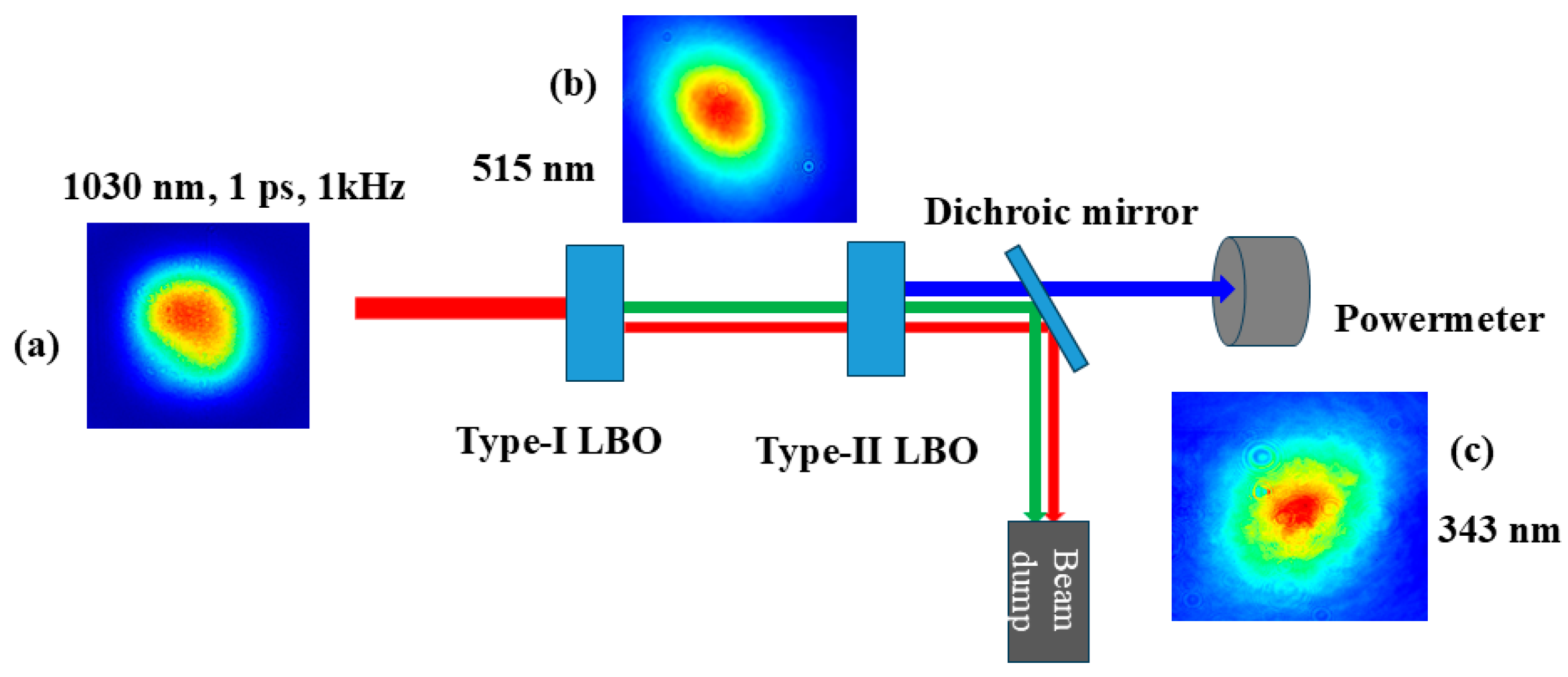
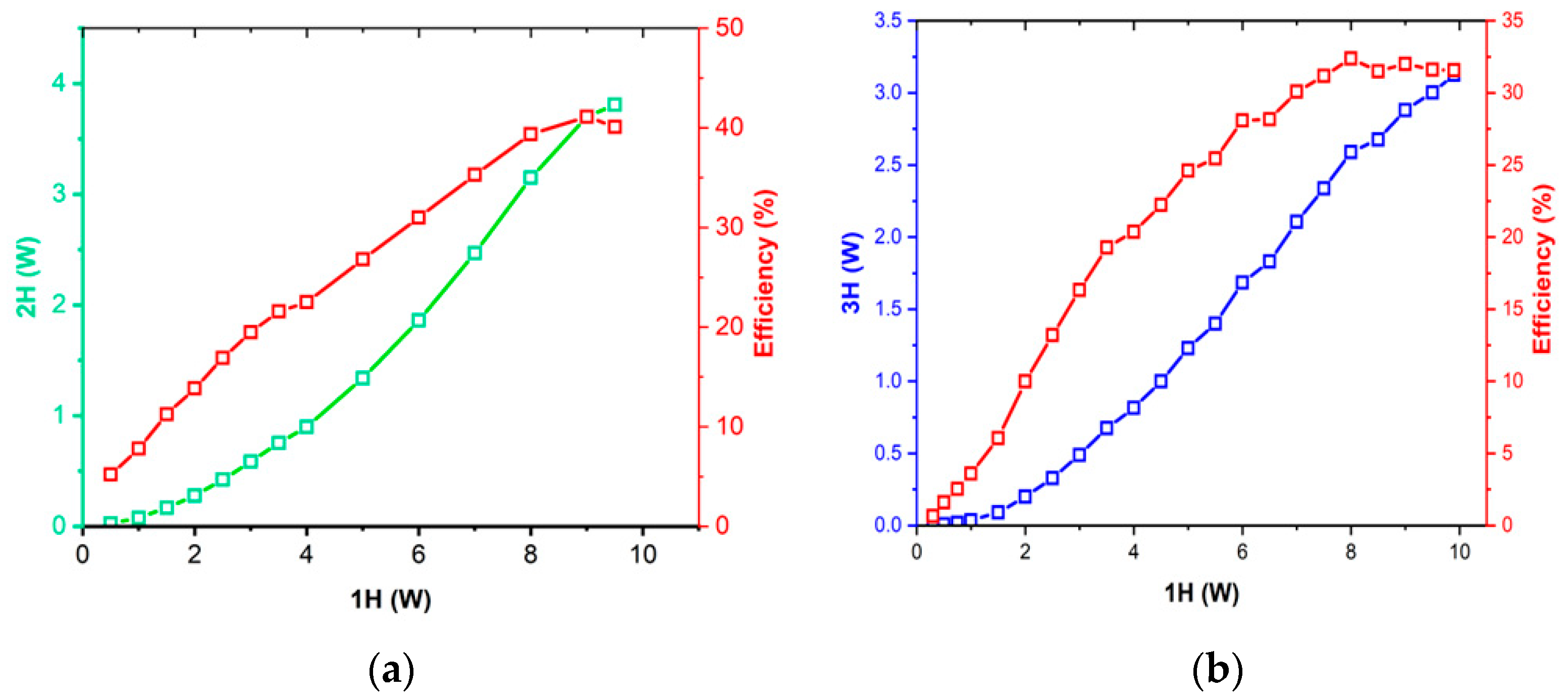
3.1. Third-Harmonic Generation for LIDT

A 343 nm UV wavelength is generated with good conversion efficiency and is a convincing beam profile for the LIDT experiment. The fundamental 1H beam 1030 nm wavelength is used for the second-harmonic generation. The second-harmonic 2H beam (515 nm), at a size of 4.7 mm, is generated in AR-coated type I LBO crystal and the ellipticity is 0.85. AR-coated LBO type II crystal is used to mix the fundamental (1H) and second-harmonic generation (2H) to generate a third-harmonic (3ω = 2ω + 1ω) beam, 3.06 mm in diameter and with an ellipticity of 0.8. The crystal lengths of chosen LBO crystals are 1.8 mm and 2.6 mm for 2H and 3H generation, respectively [15,16]. Figure 2 exhibits the output power and conversion efficiency of the 2H beam and 3H beam.
Figure 2a clearly demonstrates that as the average power of the fundamental frequency increases, the power of the second harmonic (2H) also increases. The efficiency of the SHG is compensated for the third-harmonic generation. For 7W of input power, the SHG beam profile was good and the corresponding conversion efficiency was 35.7%. The conversion efficiency of the third harmonic for the 7W (1H) input beam was 30%. Above 7W of input power, the conversion efficiency of 3H starts to saturate, which can be seen from the plateau in the curve (Figure 2b), due to back conversion [17]. The converted 343 nm wavelength remains stable throughout the LIDT experiment. The conversion efficiency from the second harmonic beam to the third-harmonic beam is 60%.

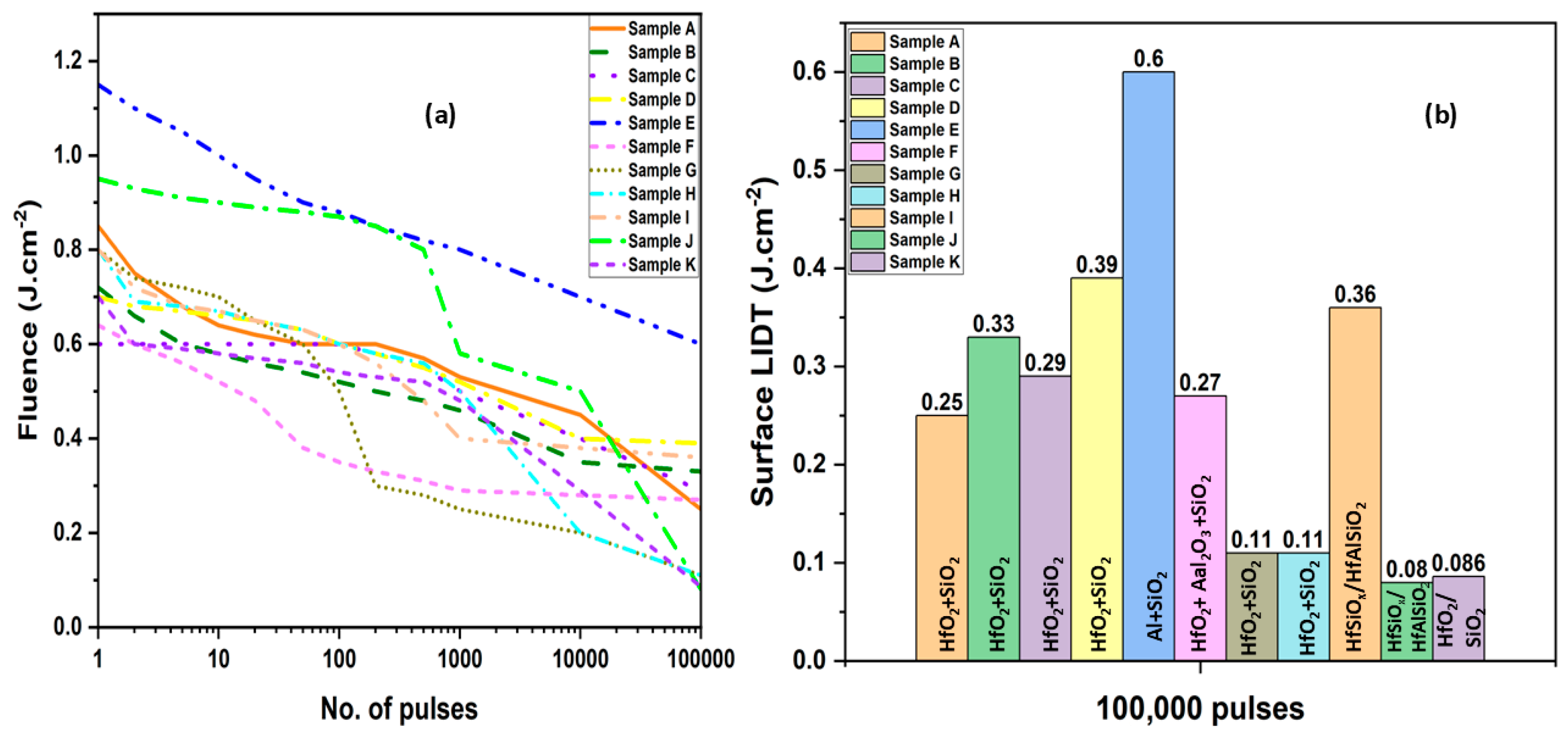
3.2. UV Laser-Induced Damage Threshold Testing

This LIDT experiment is a part of the LIDT damage challenge organized annually by HiLASE [18]. This LIDT challenge by HiLASE represents the current state-of-the-art in UV damage resistance of optical coatings. Our protocol goes beyond standard testing by comparing single- and multi-shot thresholds, identifying safe zones, analyzing damage morphology, and comparing the coatings from multiple suppliers under identical test conditions. This study provides a comprehensive range of damage thresholds for commercially available UV optics.
In the present work, we tested the LIDT of the AR-coated windows for 343 nm. The lifetime of the 343 nm coated optical components is limited because these coatings are subjected to degradation due to long exposures [19]. The test was designed for 2-inch optics, with an angle of incidence (AOI) of 0°, and an AR coating with a central wavelength of 343 nm, designed for the ultrashort pulses. The experiment is set for the wavelength of 343 nm with a 1 mm diameter p-polarized Gaussian beam. Overall, seven companies challenged their optics in the competition, with eleven individual samples. The beam diameter is confined to 1 mm, using a plano-convex lens f = 1000 mm on the surface of the sample. Before the experiment, the corresponding fluence for each attenuator setting is calculated and recorded. This provides an accurate selection of the desired attenuator position to achieve a specific fluence during the experiment. The beam profile and the energy were diagnosed using a beam profiler and power meter. Damage diagnostics were first monitored in the fast camera; the data were recorded and then compared with microscope observation. The damage-detection camera prevents catastrophic damage to the optics and the resulting contamination caused by the debris. Aftermath damage was confirmed using a laser scanning microscope with a 20× objective. Analyzing the damage sites using the Normarski microscope helps to identify the damage sites which are not visible in the fast camera and also helps in analyzing the damage morphology [18]. Laser-induced permanent change in the optics that are observed under the microscope is marked as damage. For each sample, the test is conducted over 80% of the optical clear aperture using a total of 367 sites. During the experiment, the test spots were exposed to the laser following the ISO 21254 1-on-1 (one shot in one spot) and S-on-1 (multiple shot in one spot) scheme. For each spot, the energies were set specifically with a fluence difference of 0.12 J·cm−2 for a systematic study. For statistical purposes, four sites are tested with the same condition, i.e., fluence and number of pulses. Because of the stable laser and large spot size, the error value is kept below 6% of the calculated fluence.
Details of the samples tested are provided in Table 1. All the substrates were UV-grade fused silica (UVFS) that were coated or fabricated with different materials and techniques, like ion beam sputtering and e-Beam evaporation techniques. Test results of the characteristic damage curve for each sample are evaluated and provided as a graph in Figure 3a. The detailed LIDT testing provides a damage curve, but it does not give a direct answer as to which UV window sample has a high LIDT. From the 1-on-1 test, sample E, coated by ion beam sputtering (IBS), exhibits the highest LIDT value, of 1.15 J·cm−2, and other IBS coating values range from 0.95 to 0.6 J·cm−2. The e-Beam coating samples F, G and H show values of 0.64, 0.8 and 0.8 J·cm−2, respectively in the 1-on-1 test. This test will not provide a concrete conclusion of there being a high LIDT, so the test was extended from 2 to 100,000 pulses, using equal intervals of every 0.12 J·cm−2. During the S-on-1 test, the LIDT value started to drop in most of the coatings. Samples A, B, C and D show a decent LIDT value (0.7–0.9 J·cm−2) for the 1-on-1 test. The values also remained stable until 500 pulses and on the longer pulses, the LIDT value dropped dramatically to (0.26–0.4 J·cm−2). Samples A–D share the same parameters in terms of the UVFS substrate, IBS coating technique, and HfO2/SiO2 coating materials, differing only in coating thickness. Sample F, G, and H are coated by the e-Beam evaporation technique with HfO2/Al2O3/SiO2, HfO2/SiO2 and HfO2/SiO2, respectively. Among all the samples, the LIDT value of sample F is the smallest (0.6 J·cm−2) for the 1-on-1 test but from 50 to 100,000 shots, the plateau remains stable and the LIDT value remains the same. Though sample G and H showed a promising LIDT value in the beginning, their values dropped dramatically at 200 pulses and 10,000 pulses. At 100,000 pulses, the LIDT value of G and H is 0.11 J·cm−2. Sample I is as deposited, and sample J is annealed at 300 °C for 10 h with HfSiOx/HfAlOx. For a few hundred pulses, the sample I LIDT value slowly dropped and then remained the same as the other samples for the 100,000 pulses. Sample J performs well on the 1-on-1 test with an LIDT value of 0.9 J·cm−2, and remains stable up to 500 pulses. There was a sudden drop at 1000 shots and the value remains stable until 10,000 shots, followed by a sudden drop to 0.08 J·cm−2. The as-prepared sample I shows a better LIDT value than the annealed sample J after 20,000 shots. The performance of sample K was good on the 1-on-1 test, with a stable LIDT until 500 shots, gradually starting to decrease to 0.086 J·cm−2.
Generally, coating with Al provided a good threshold value for the 1-on-1 test, and in our case, the value kept decreasing but remained highest among tested samples. The characteristic curve of sample E coated with Al2O3/SiO2 by IBS technique provided a reasonable LIDT value for the longer exposure, which is evident from the curve in the graph (Figure 3). In general, the aluminum-based coating facilitates a high damage threshold in the UV regime and our LIDT damage threshold shows a four-times-higher LIDT value for Al2O3 compared with the HfO2 sample. Coating the windows with Al2O3/SiO2 can withstand the oxidation compared to pure aluminum, which is very sensitive to scratches in the optics. The IBS technique offers dense and superior surface structures with ultra-low loss.
Sample A, G, H, J and K show no plateau at 100,000 shots and the LIDT value (0.08–0.26 J·cm−2) is poor, leading to the substrate failure which is observed during the experiment; the lack of a plateau confirms the degradation of the optics. In high-energy UV lasers, substrate failure is a critical issue that undermines the laser’s performance. In our test, the LIDT value of samples B and D slowly drops and then starts to be stable from 10,000 pulses where the curve follows a similar pattern. The LIDT of sample C was stable until 500 shots and then decreased. Many samples did not show the expected damage threshold plateau. The laser damage theory predicts that with an increase in pulse count, the threshold value drops and then stabilizes after a few hundred pulses, which is then independent of the pulse count. This allows a safe fluence level for the operation of the laser. But in the present work, most of the samples tested did not show this standard behavior, other than sample F. This is because the high energy of UV light breaks the bonds in the material. The repeated pulse gradually weakens the optics and modifies the material, and that leads to incubation effects that cause the drop in LIDT value and absence of the plateau. The long-term stability of optics tested for the 105 pulses is presented in Figure 3b. In the present study, long-term exposure is regarded as representative of the long-term stability of the sample. Among the tested samples, sample E shows a high LIDT value of 0.6 J/cm2, which is two times higher than the other samples tested, which is roughly 0.3 J/cm2.
The information about the coating thickness of some companies is proprietary, and so cannot be discussed in the present work. At the same time, the thickness did not have much of an influence on the laser damage threshold value, which is evident from samples A–D, with the same coating material (HfO2/SiO2) and technique (IBS) but with different thicknesses.

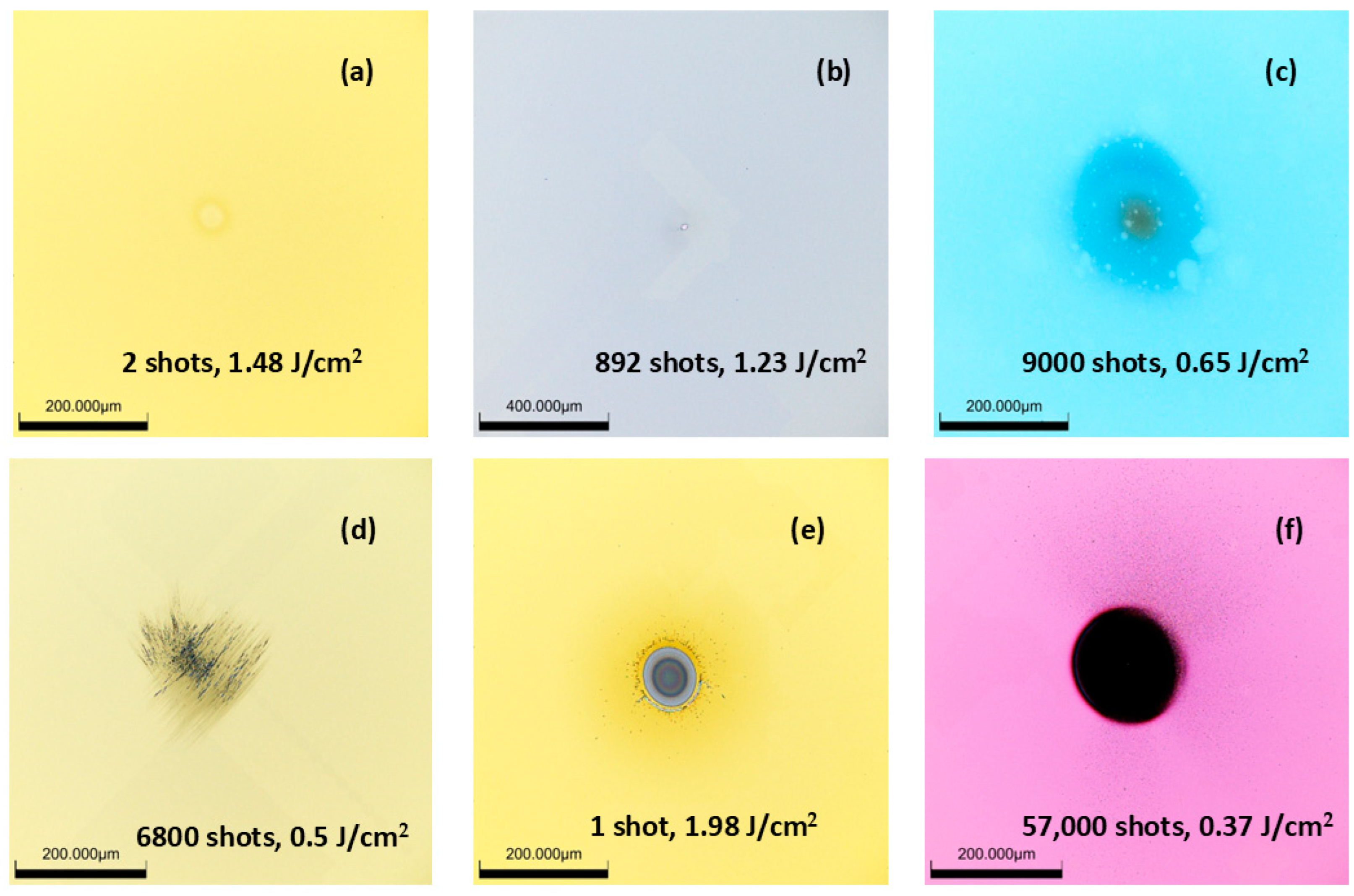
3.3. Morphology of Laser Damage

Laser irradiation on the coating above a certain energy density induces permanent damage and these changes cause loss in the properties of coatings. Any changes that are seen in the irradiated spot are considered as damage because these changes can develop into huge damage after a few thousand pulses [20]. This damage will generate a hotspot, distort the beam, and further propagate to damage the other optics in the laser. Identifying these damages at the early stage to stop catastrophes in the future and at the same time choosing optics with a high damage threshold is very important for the operation of a high-power laser [11]. The mechanism involved in this laser damage is dependent on the properties of coated materials and their response during ultrafast irradiation. From the damage morphology, we can confirm the physical mechanism involved in the laser damage experiment.
In general, any factors can influence laser damage morphology, like wavelength, pulse length, repetition rate, number of pulses, spot size and energy density. In the 1-on-1 test, the sites are exposed to near-threshold fluence, with one shot of pulse displaying different types of damage morphologies, ranging from discoloration, blistering and crater formation for various samples. In the case of the multi-pulse or S-on-1 (ISO 212542) test, the damage morphology has determinable behavior, where the data points between the fluence and number of pulses form a curve representing damage sites [11,21]. Figure 4a shows the curve of fluence value at which the damage occurs for sample E. The insert shows a variable damage morphology occuring above the threshold. The crater can be formed at a single shot at high fluence (1.45 J/cm2) and at 1000 shots at lower fluence (1.2 J/cm2). At the same time, discoloration occurred at 500 shots at 1.25 J/cm2. The S-on-1 test shows the growth of damage and the effect of the long operation of the laser at one spot. Figure 4b is the sample surface of sample E recorded by the Normarski microscope after the LIDT experiment.
Figure 5 shows the laser damage morphologies that occurred during the interaction of the UV picosecond laser on the coatings at various fluence and pulses and the discussion on the occurrence of the morphology during this interaction is given below. Figure 5a shows the discoloration damage for two shots of 1.48 J/cm2. This happens near the damage threshold either a single or multiple shots. Though it will not affect the reflectivity of the optics, this initiates catastrophic damage after continuous irradiation or higher fluence. The UV photons cause the electrons to enter defect states which, creates the colored center. This damage can be identified from the visible color change observed in the Normarski microscope [22]. Intrinsic defects are the reason for the pinhole/pinpoint (Figure 5b), damage in the surface and there is a possibility this damage can expand to the surroundings to form group defect damage. Ultrashort pulse irradiation on the optical coatings leads to softening of the coatings. The pinpoint defect is the nucleation for larger defects. In Figure 5c, the repetitive stress and relaxation of the material creates blistering. In this stage, the subsurface of the coating is peeled off or delaminated where the material is not fully removed. Blistering looks like a bubble-like formation on the surface, which leads to peeling or crater formation with a higher fluence or pulse count [23]. The nano-cracks in Figure 5d are due to the formation of nano-bumps, which leads to the surface roughness with a few pulses, and an increase in the number of pulses initiates the formation of cracks on the surface [24]. The stress wave created by the high number of laser pulses propagates through the material, which causes failure at the weak points on the coatings. The crater formation can be witnessed both in S-on-1 and 1-on-1 tests, with a single shot and high fluence and multiple shots and a low fluence, respectively, in Figure 5e and Figure 5f. The depth and size of the crater differ depending on the fluence and lodging depth. Craters are formed by absorption in deep defects, which leads to the removal of two layers of material in the optics [25]. During this process, the material melts on a small scale and the repeated buildup of the temperature and pressure in the site leads to fracture. As shown in Figure 5e, a distinct crater is observed in the 1-on-1 test at a fluence of 1.98 J/cm2. In contrast, at a lower fluence of 1.48 J/cm2 with two laser shots (Figure 5a), the damage is limited to surface discoloration. In Figure 5f, the damage morphology appeared to evolve from discoloration to blistering and eventually grew to a large crater at a constant fluence, as the number of laser shots increased from 1 to 57,000.
In this study, sample E, coated with Al2O3/SiO2 using the IBS technique from the manufacturer EKSMA optics, demonstrates superior stability compared to other coatings at 105 pulses. From our results, it is concluded that many renowned companies in the market that coated their UV optics with HfO2/SiO2 did not achieve satisfactory LIDT results. As previously discussed, even minor changes in the laser-irradiated region are considered damage, as they worsen with increased energy or pulse count. Continuous laser damage testing of the optics is necessary to enhance their quality and ensure the safe operation of high-power lasers.

4. Conclusions

LIDT setup was upgraded to enable the conversion of the fundamental 1030 nm wavelength to 343 nm, allowing us to investigate the damage threshold of UV optics. At an average of 3 W power, the third-harmonic output (343 nm) exhibited a beam size of 3.06 mm, an ellipticity of 0.8, and conversion efficiency of 28.6%. Eleven AR-coated UV window samples from major manufacturers were tested, each featuring varying coating materials, techniques, and thicknesses tailored for UV applications. The study reveals most industrial-grade optics did not meet the desired resilience for high pulse counts and ended up in substrate failure. Among the tested optics, sample E from the “EKSMA optics” coated with Al2O3 shows the highest limiting threshold of 0.6 J/cm2 for the long-term exposure of 100,000 shots, indicating the highest resistance and suitability for UV laser application. Few LIDT studies have been conducted on UV optics, yet such research is critical for enhancing performance and identifying the factors that reduce LIDT values. Understanding LIDT in the UV range is essential for designing high-precision, high-power laser systems that can operate safely and reliably, especially in applications like photonics, materials processing, and optical research.

Author Contributions

P.N.: writing—review and editing, writing—original draft, visualization, methodology, investigation, formal analysis, conceptualization. M.M.: writing—review and editing, visualization, methodology, investigation, formal analysis, conceptualization. H.T.: writing—review and editing, writing—original draft, visualization, methodology, investigation, formal analysis, conceptualization. M.G.M.: formal analysis, writing—review and editing. O.N.: formal analysis, writing—review and editing. J.V.: writing—review and editing, validation, supervision. J.B.: supervision. All authors have read and agreed to the published version of the manuscript.

Funding

This work was co-funded by the European Union and the state budget of the Czech Republic under the project LasApp CZ.02.01.01/00/22_008/0004573.

Data Availability Statement

The data will be made available upon request.

Conflicts of Interest

The authors declare no conflicts of interest.

Abbreviations

The following abbreviations are used in this manuscript:
LIDTLaser-induced damage threshold
ARAnti-reflective
IBSIon beam sputtering
LBOLithium borate
SHGSecond-harmonic generation
THGThird-harmonic generation

References

  1. Ristau, D.; Jupe, M.; Starke, K. Laser damage thresholds of optical coatings. Thin Solid Films 2009, 518, 1607–1613. [Google Scholar] [CrossRef]
  2. Smrž, M.; Chyla, M.; Muzik, J.; Nagisetty, S.S.; Novak, O. Compact picosecond KW-class thin-disk laser Perla for hi-tech industrial applications. MM Sci. J. 2019, 2019, 3620–3625. [Google Scholar] [CrossRef]
  3. Hauschwitz, P.; Jagdheesh, R.; Alamri, S.; Rostohar, D.; Kunze, T.; Brajer, J.; Kopeček, J.; Mocek, T. Fabrication of functional superhydrophobic surfaces on carbon fibre reinforced plastics by IR and UV direct laser interference patterning. Appl. Surf. Sci. 2020, 508, 144817. [Google Scholar] [CrossRef]
  4. Falmbigl, M.; Godin, K.; George, J.; Mühlig, C.; Rubin, B. Effect of annealing on properties and performance of HfO2/SiO2 optical coatings for UV-applications. Opt. Express 2022, 30, 12326–12336. [Google Scholar] [CrossRef]
  5. Douti, D.L.; Gallais, L.; Hecquet, C.; Begou, T.; Lumeau, J.; Commandre, M. Analysis of energy deposition and damage mechanisms in single layer optical thin films irradiated by IR and UV femtosecond pulses. Proc. SPIE 2015, 9627, 962718. [Google Scholar] [CrossRef]
  6. Kozlov, A.; Lambropoulos, J.C.; Oliver, J.B.; Hofman, B.N.; Demos, S.G. Mechanisms of picosecond laser induced damage in common multilayer dielectric coatings. Sci. Rep. 2019, 9, 607. [Google Scholar] [CrossRef]
  7. Qiu, S.R.; Norton, M.A.; Raman, R.N.; Rubenchik, A.M.; Boley, C.D.; Rigatti, A.; Mirkarimi, P.B.; Stolz, C.J.; Matthew, M.J. Impact of laser-contaminant interaction on the performance of the protective capping layer of 1 ω high-reflection mirror coatings. Appl. Opt. 2015, 54, 8607–8616. [Google Scholar] [CrossRef]
  8. Nuter, R.; Kandy, A.K.; Gallais, L.; Grosjean, S.; Lamaignere, L.; Wagner, F.; Natoli, J.-Y. Influence of laser polarization on the laser-induced damage threshold: Comparison with photonionization theory. J. Appl. Phys. 2025, 137, 025901. [Google Scholar] [CrossRef]
  9. Novák, O.; Miura, T.; Smrž, M.; Chyla, M.; Nagisetty, S.S.; Mužík, J.; Linnemann, J.; Turčičová, H.; Jambunathan, V.; Slezák, O.; et al. Status of the High Average Power Diode Pumped Solid State Lasers Development at HiLASE. Appl. Sci. 2015, 5, 637–665. [Google Scholar] [CrossRef]
  10. Vanda, J. Progress in design of advanced LIDT station in HiLASE project. Proc. SPIE 2015, 9442, 94421E. [Google Scholar] [CrossRef]
  11. Skoda, V.; Vanda, J.; Uxa, S. A comparison of LIDT behavior of metal-dielectric mirrors in ns and ps pulse regime at 1030 nm with regard to the coating technology. Proc. SPIE 2017, 10447, 1044729. [Google Scholar] [CrossRef]
  12. Divoky, M.; Smrz, M.; Chyla, M.; Sikocinski, P.; Severova, P.; Novák, O.; Huynh, J.; Nagisetty, S.S.; Miura, T.; Liberatore, C.; et al. HiLASE: Development of fully diode pumped disk lasers with high average power. Proc. SPIE 2014, 9255, 92550V. [Google Scholar] [CrossRef]
  13. Macuchova, K.; Hermanek, J.; Kaufman, J.; Muresan, M.G.; Ruzicka, J.; Rehakova, M.; Divoky, M.; Svandrlik, L.; Mocek, T. Laser beam distribution system for the HiLASE center. Proc. SPIE 2017, 10603, 1060306. [Google Scholar] [CrossRef]
  14. Boyd, R. Nonlinear Optics, 3rd ed.; Academic Press: Cambridge, UK, 2008. [Google Scholar]
  15. Smrž, M.; Mužík, J.; Štěpánková, D.; Turčičová, H.; Novák, O.; Chyla, M.; Hauschwitz, P.; Brajer, J.; Kubát, J.; Todorov, F.; et al. Picosecond thin-disk laser platform PERL A for multi-beam micromachining. OSA Continuum. 2021, 4, 940–952. [Google Scholar] [CrossRef]
  16. Andral, U.; Walch, P.; Moreno, V.; Mahieu, B.; Produit, T.; Lozano, M.; Bizet, L.; Herkommer, C.; Moret, M.; André, Y.B.; et al. Second and third harmonic generation from simultaneous high peak- and high average-power thin disk laser. Appl. Phys. B 2022, 128, 177. [Google Scholar] [CrossRef]
  17. Cech, P.; Vanda, J.; Muresan, M.G.; Mydlar, M.; Pilna, K.; Brajer, J. Laser induced damage threshold testing at HiLASE. MM Sci. J. 2019, 2019, 3657–3661. [Google Scholar] [CrossRef]
  18. Bischof, D.; Botha, R.; Vetsch, B.; Scherrer, U.; Michler, M.; Ziolek, C.; Ettemeyer, A. Introduction of an ultraviolet laser-induced degradation test system for optical coatings. In Optica OIC; Optica Publishing Group: Washington, DC, USA, 2016; ISBN 978-1-943580-13-2. [Google Scholar] [CrossRef]
  19. Ristau, D. Laser-Induced Damage in Optical Materials; CRC Press: Boca Raton, FL, USA, 2016. [Google Scholar]
  20. Vanda, J.; Sevcík, J.; Pupka, E.; Sciuka, M.; Melninkaitis, A.; Divoky, M.; Jambunathan, V.; Bonora, S.; Skoda, V.; Lucianetti, A.; et al. Comparative LIDT measurements of optical components for high-energy HiLASE lasers. High Power Laser Sci. 2016, 4, e11. [Google Scholar] [CrossRef]
  21. ISO 21254-2:2011; Lasers and Laser-Related Equipment—Test Methods for Laser-Induced Damage Threshold—Part 2: Threshold Determination. ISO: Geneva, Switzerland, 2011.
  22. Smalakys, L.; Momgaudis, B.; Grigutis, R.; Kičas, S.; Melninkaitis, A. Contrasted fatigue behavior of laser-induced damage mechanisms in single layer ZrO2 optical coating. Opt. Express 2019, 27, 26088–26101. [Google Scholar] [CrossRef]
  23. Sladek, J.; Mirza, I.M. Laser induced damage threshold of silicon with native and artificial SiO2 layer. MM Sci. J. 2019, 2019, 3579–3584. [Google Scholar] [CrossRef]
  24. Rudenko, A.; Mauclair, C.; Garrelie, F.; Stoian, R.; Colombier, J.P. Light absorption by surface nanoholes and nanobumps. Appl. Surf. Sci. 2019, 470, 228–233. [Google Scholar] [CrossRef]
  25. Rubenchik, A.M.; Feit, M.D. Initiation, Growth and Mitigation of UV Laser Induced Damage in Fused Silica. Proc. SPIE 2002, 4679, 79–95. [Google Scholar] [CrossRef]
Figure 1. Schematic representation of third-harmonic generation. (a) Fundamental energy (1030 nm) fluence profile at input face of Type-I LBO crystal. (b) Beam profile of frequency-doubled beam 75 cm after LBO crystal at optimal input intensity. (c) Third-harmonic generated beam after Type-II LBO crystal. Red, green and blue colors represent wavelengths of 1030 nm, 515 nm and 343 nm, respectively.
Jmmp 09 00180 g001
Figure 2. (a) Second-harmonic generation and conversion efficiency of fundamental beam from Yb: YAG thin-disk laser system using type I LBO crystal; (b) third-harmonic generation and conversion efficiency by mixing fundamental and SHG for type II LBO crystal.
Jmmp 09 00180 g002
Figure 3. LIDT results from the S-on-1 methodology: (a) characteristic damage curves extracted from the LIDT experiment; (b) LIDT value for hundred-thousand pulses on the front end of the coating.
Jmmp 09 00180 g003
Figure 4. (a) The number of shots vs. fluence above the damage threshold. The insert shows the damage morphology. (b) The surface of sample E tested for LIDT.
Jmmp 09 00180 g004
Figure 5. Various damage morphologies observed throughout experiment recorded in Normarski microscope in high resolution. (a) Discoloration, (b) pinhole/pinpoint, (c) blistering, (d) nanocracks, (e) crater, and (f) crater.
Jmmp 09 00180 g005
Table 1. Parameters of AR-coated windows used for S-on-1 LIDT tests with 343 nm and 1 mm laser beam.
Sample CodeCoating MaterialCoating TechniqueNo. of LayersCoating Thickness
(mm)
Damage Threshold (J/cm2)
AHfO2/SiO2IBS292.91 nm0.26
BHfO2/SiO2IBS292.96 nm0.33
CHfO2/SiO2IBS290 nm0.29
DHfO2/SiO2IBS291 nm0.39
EAl2O3/SiO2IBS291.51 nm0.6
FHfO2/Al2O3/SiO2e-Beam evaporation3- 0.27
GHfO2/SiO2e-Beam evaporation289.1 nm0.11
HHfO2/SiO2e-Beam evaporation2-0.11
IHfSiOx/HfAlOx IBS2-0.36
JHfSiOx/HfAlOxIBS2-0.08
KHfO2/SiO2e-Beam evaporation290 nm0.086
Disclaimer/Publisher’s Note: The statements, opinions and data contained in all publications are solely those of the individual author(s) and contributor(s) and not of MDPI and/or the editor(s). MDPI and/or the editor(s) disclaim responsibility for any injury to people or property resulting from any ideas, methods, instructions or products referred to in the content.

