

Improved Microstructure Evolution and Corrosion Resistance in Friction-Welded Dissimilar AISI 1010/D3 Steel Joints Through Post-Weld Heat Treatment

 ,
,  , , and
Abstract
1. Introduction
2. Materials and Methods
3. Results and Discussion
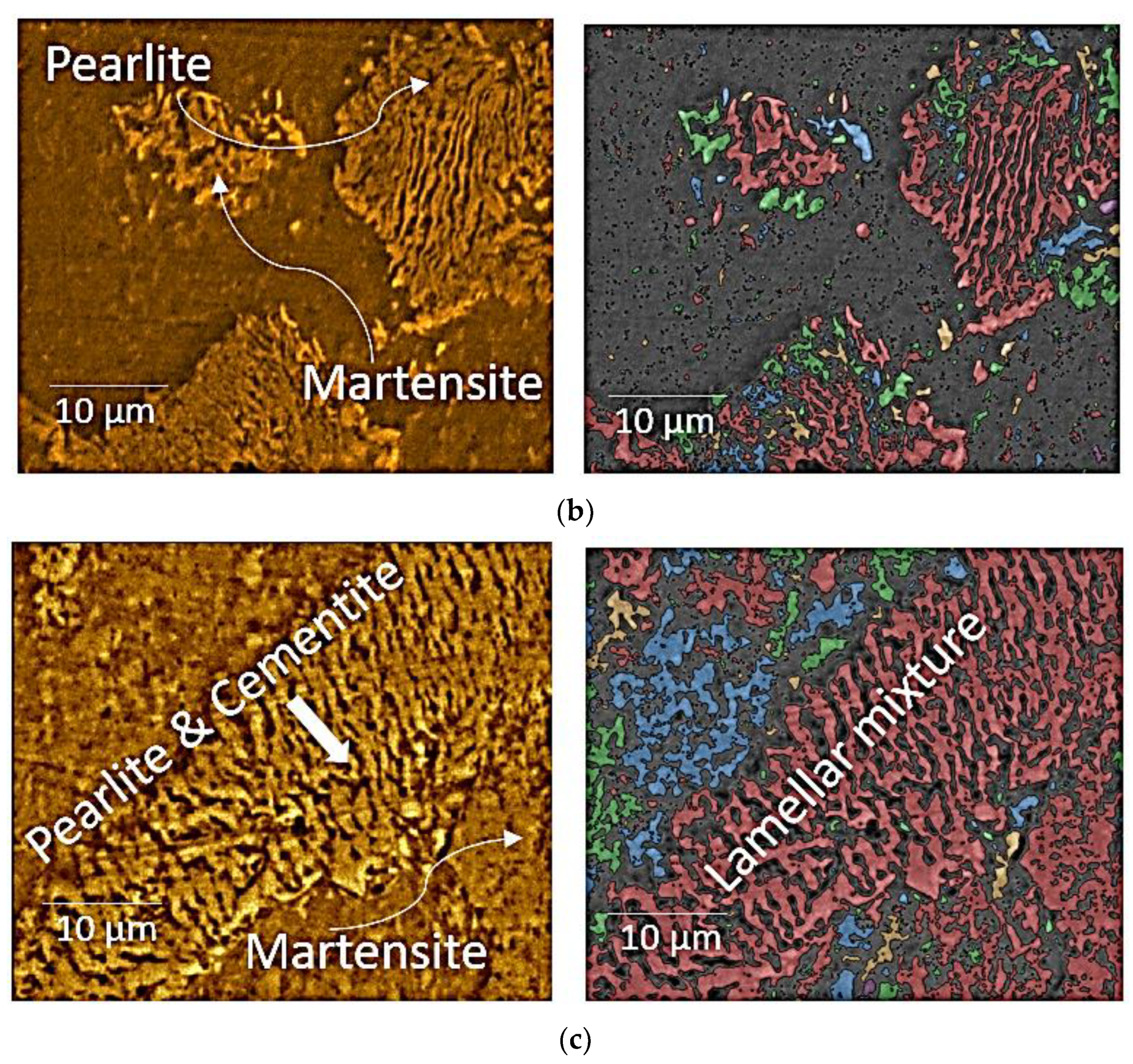
3.1. Microstructural Evaluation
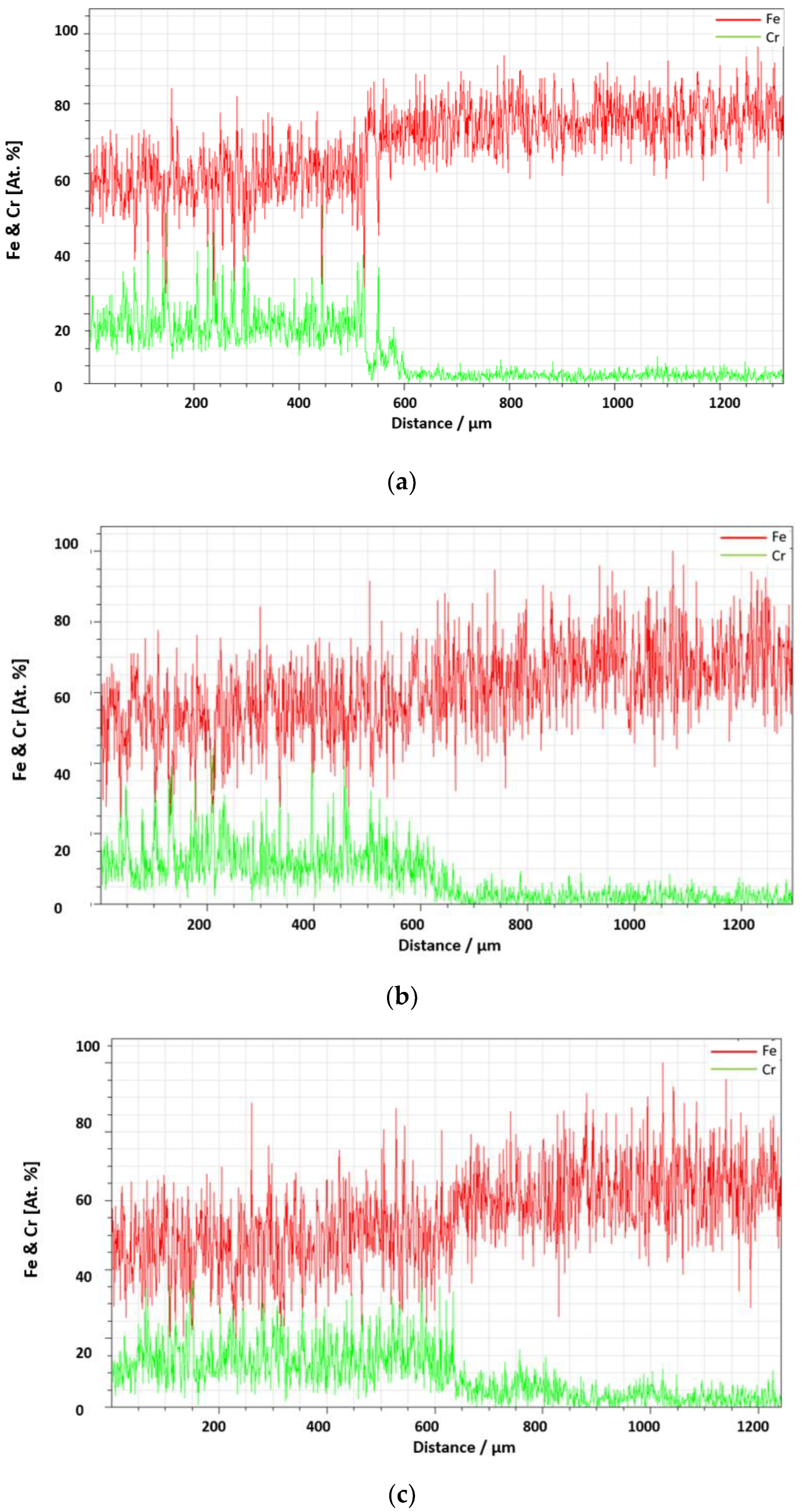
3.2. EDX and XRD Analysis
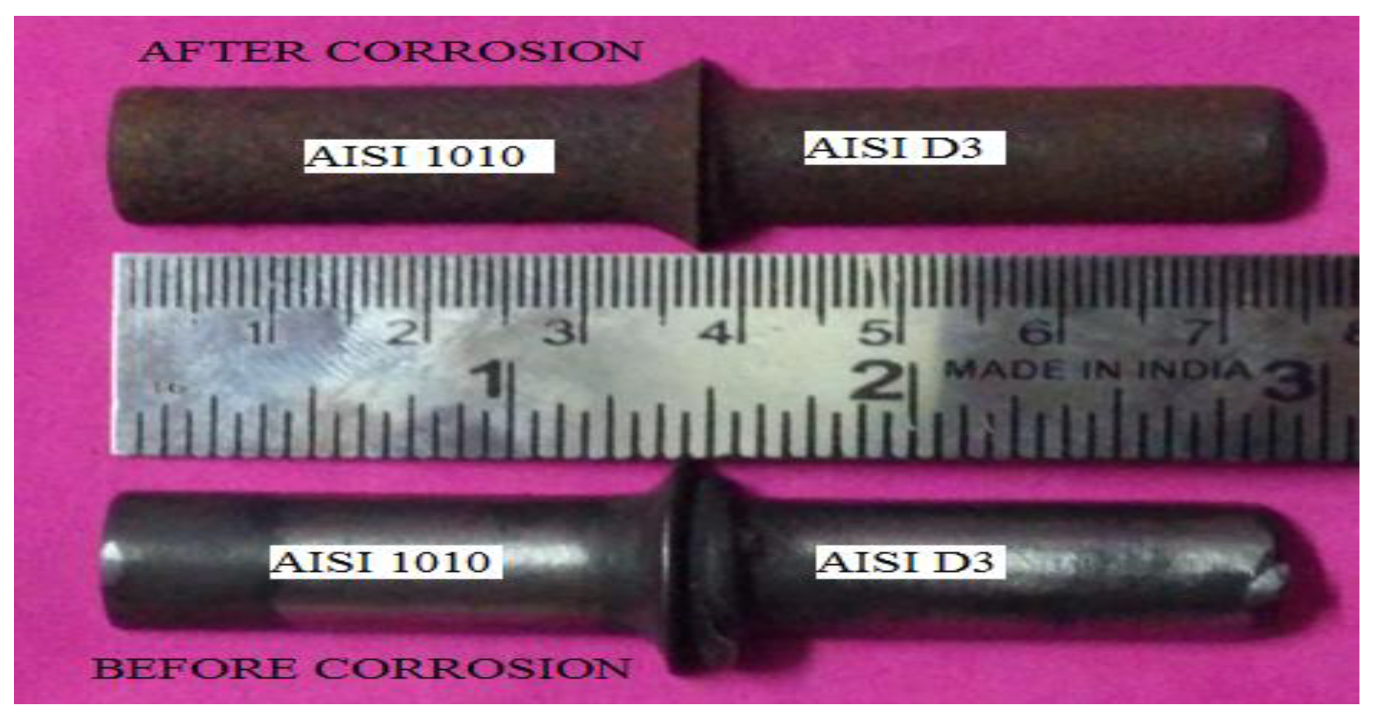
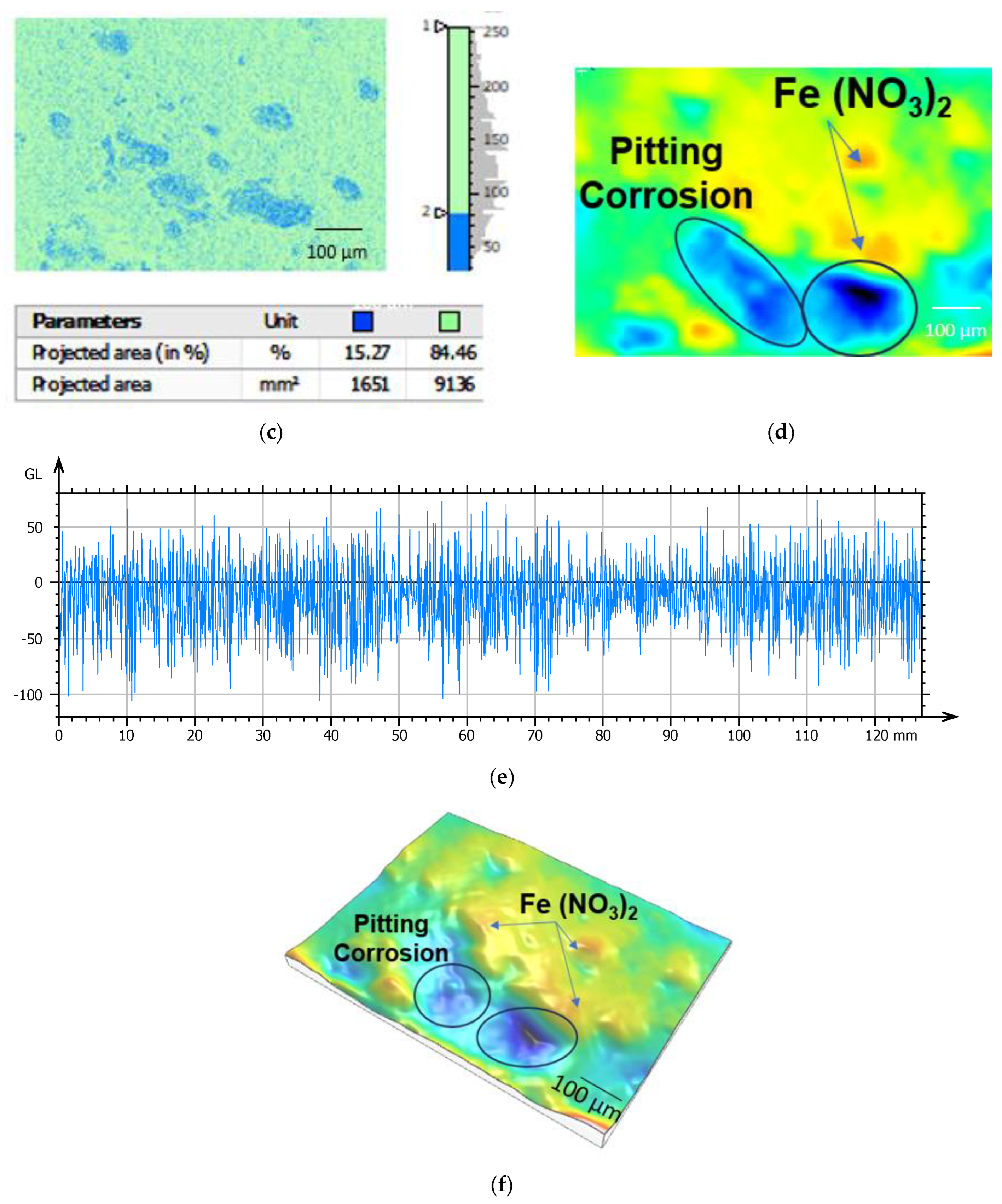
4. Corrosion Effects
5. Conclusions
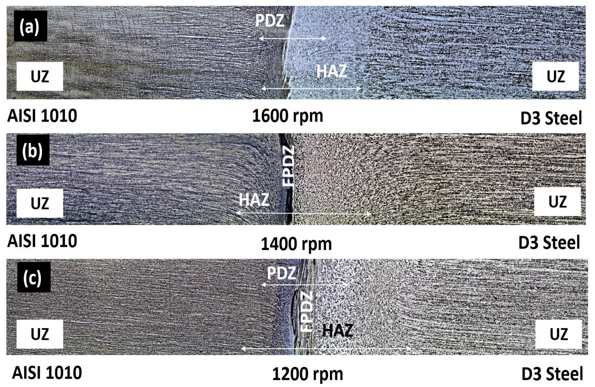
- Zone measurements at the interface of the joints shed light on the proportions of the various zones formed during friction welding. Depending on the rotating speed, the heat-affected zone (HAZ)’s width can range from 10.8 to 19.5 mm. With values ranging from 180 to 750 µm, the plastically deformed zone width varies with different kinds of steel and different rotational rates. The width of the entire deformed zone varies from 700 to 1070 µm. The fully plasticized deformed zone is between 48 and 380 microns wide.
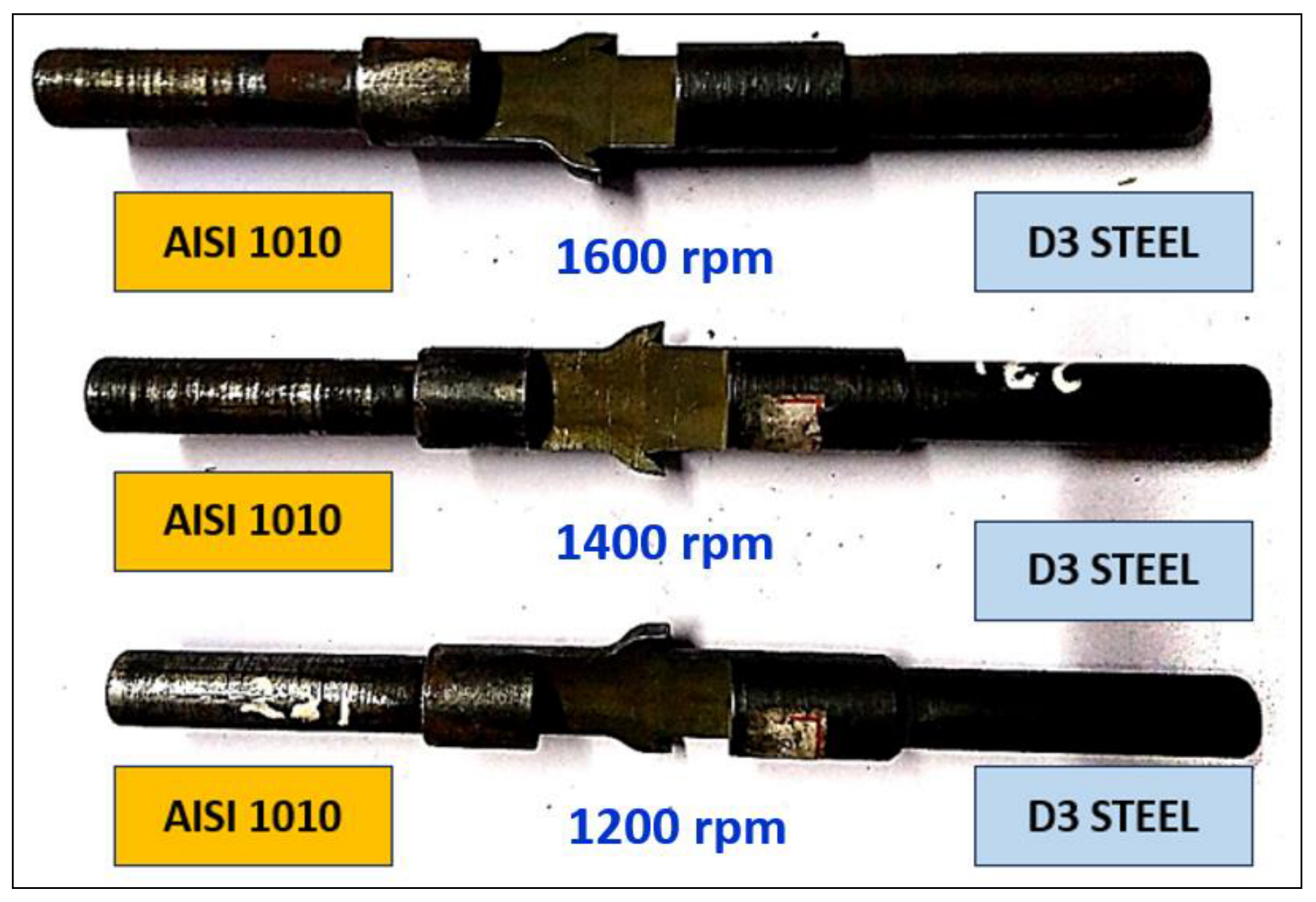
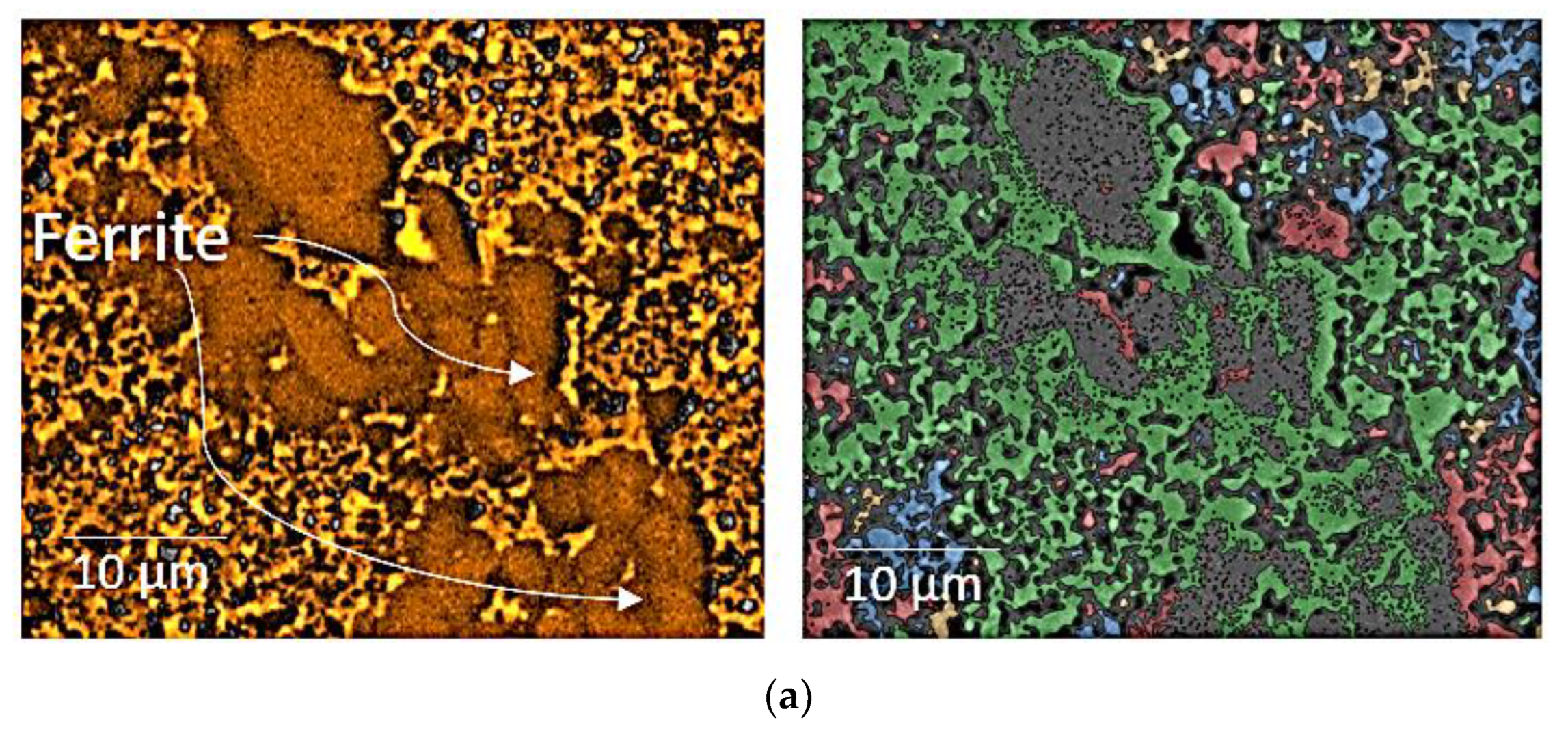
- The interface of a joint friction-welded at 1600 rpm shows fine grains of ferrite, which enhance the joint’s strength as per the Hall–Petch equation. SEM micrographs also reveal that the joint fabricated at 1600 rpm has a thin plasticized region (48 microns width) with ultra-fine grains at the interface.
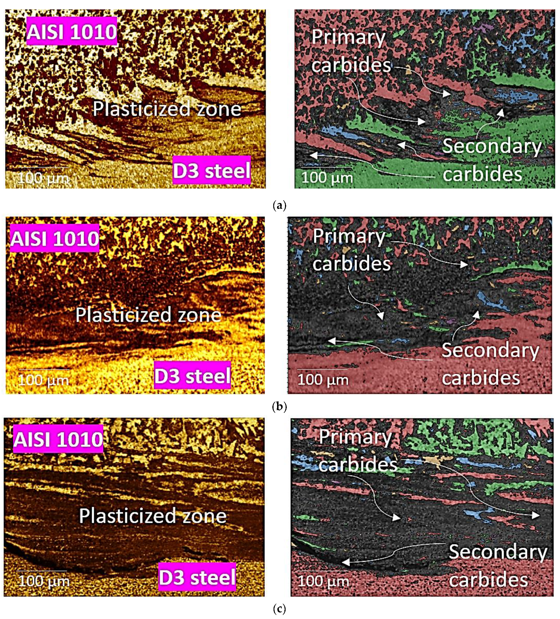
- At lower rotational speeds, there is a greater tendency for the formation of metastable, deformed phases such as M2C, which is hard and brittle.
- Though the formation of secondary carbides cannot be prevented, at higher rotational speeds primary carbides become dissolved. This reduces the tendency for the formation of an intermetallic compound and increases joint strength.
- Post-weld heat treatment results in controlled cooling, which can refine the microstructure and improve the overall material properties of dissimilar steel joints.
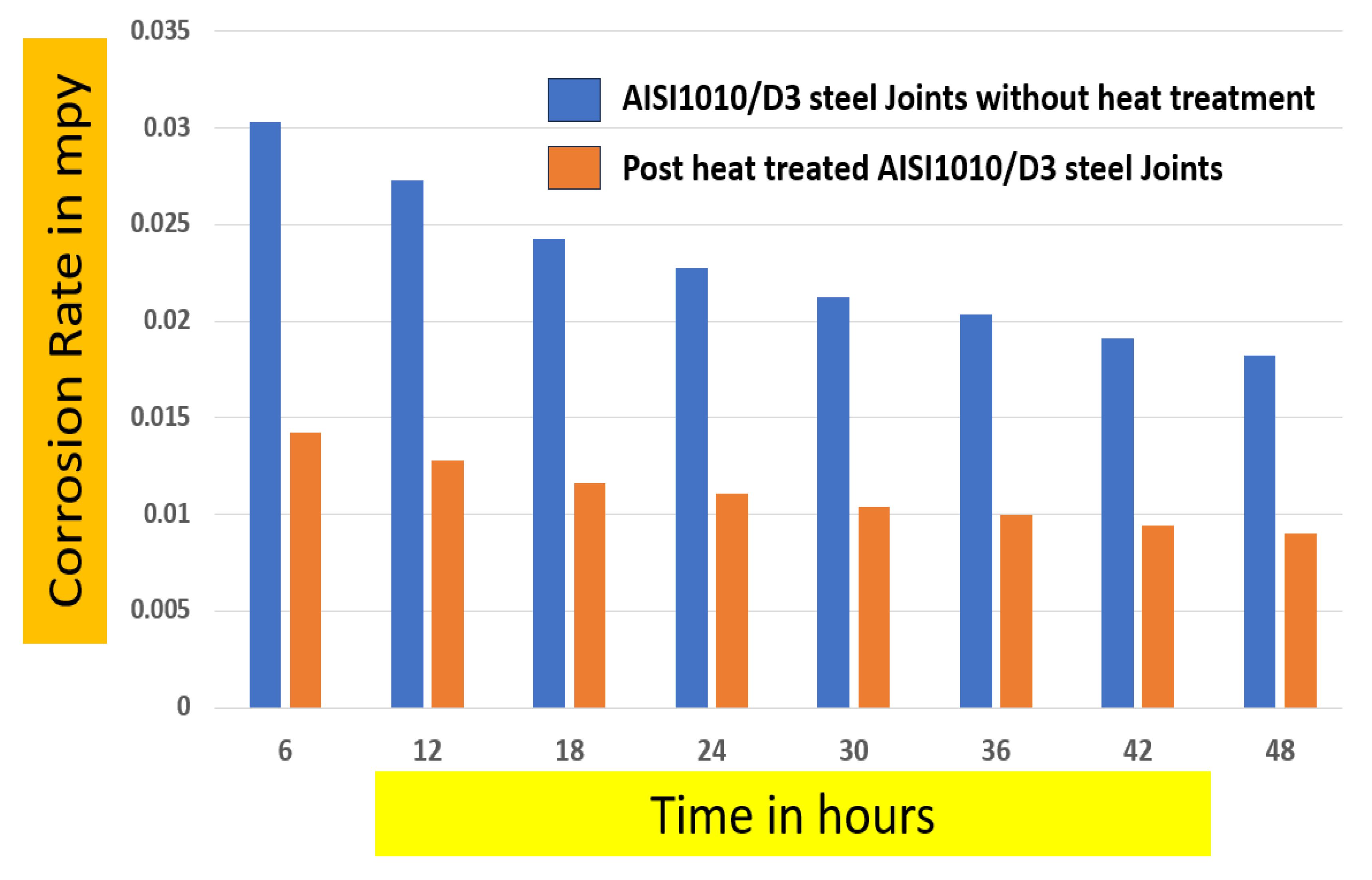
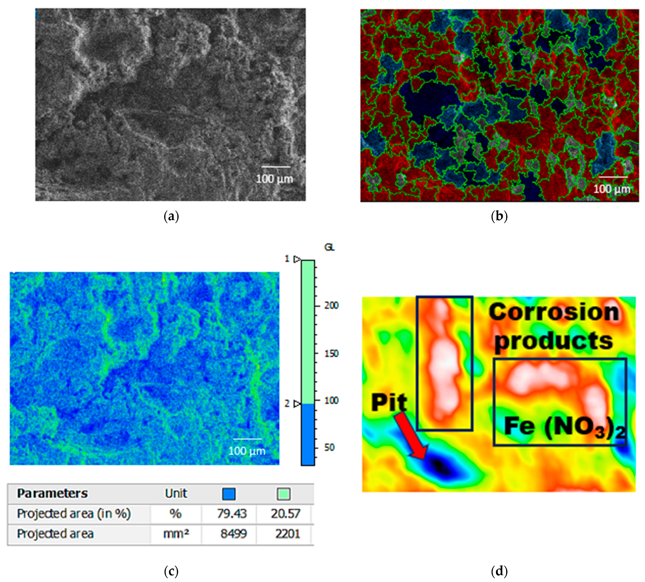
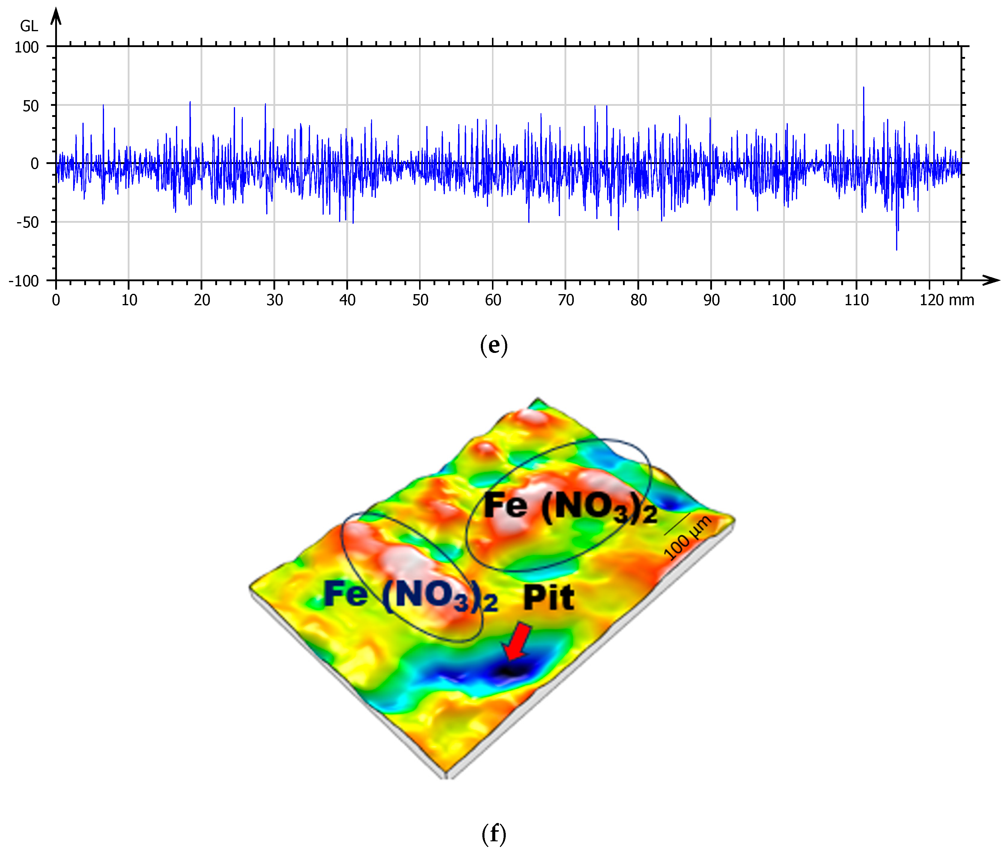
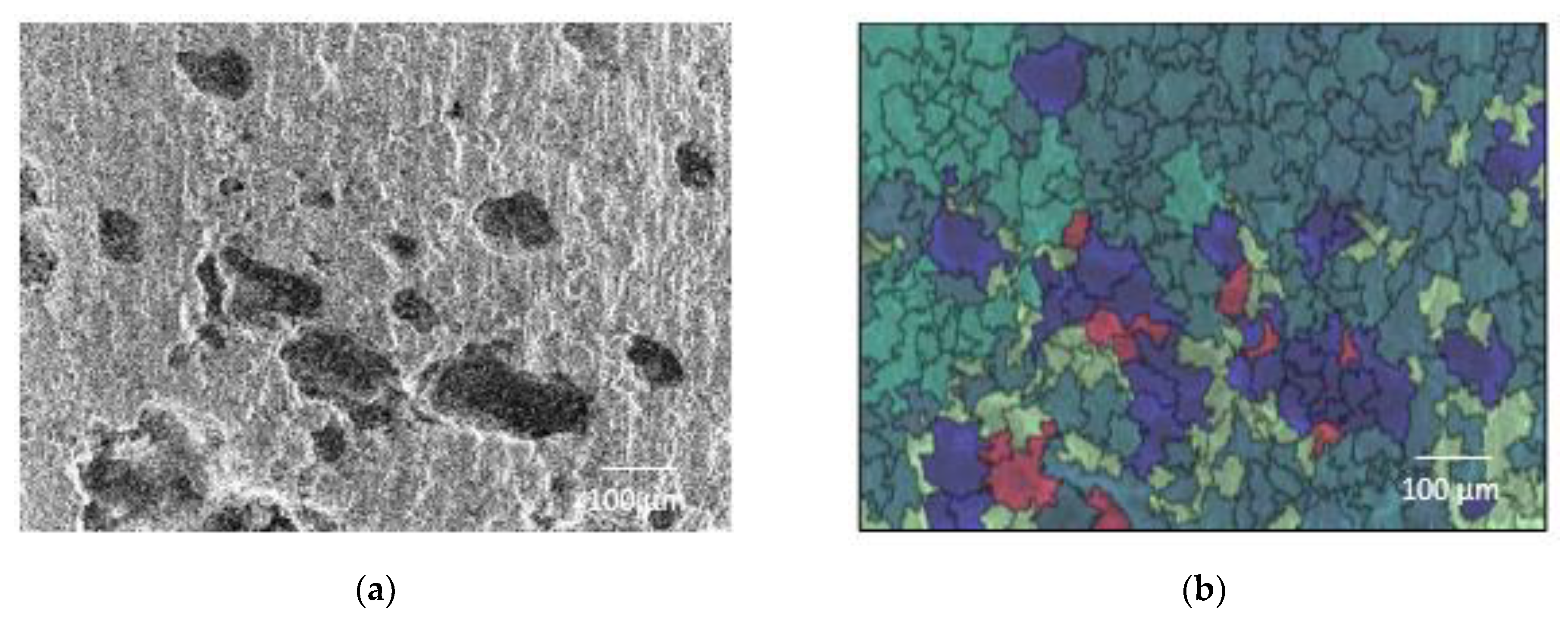
- The heat treatment of joints provided significant improvements in corrosion resistance. The untreated joint revealed coarser grains, segregated carbides, and deep pitting corrosion owing to aggressive nitric acid attack on the surface that resulted in a higher loss of material; whereas, a homogeneous distribution of the eutectic phases was observed on the surface of the heat-treated joint, which exhibited a more stable protective oxide layer reducing the probability of pitting behavior and improving the joint’s corrosion resistance.
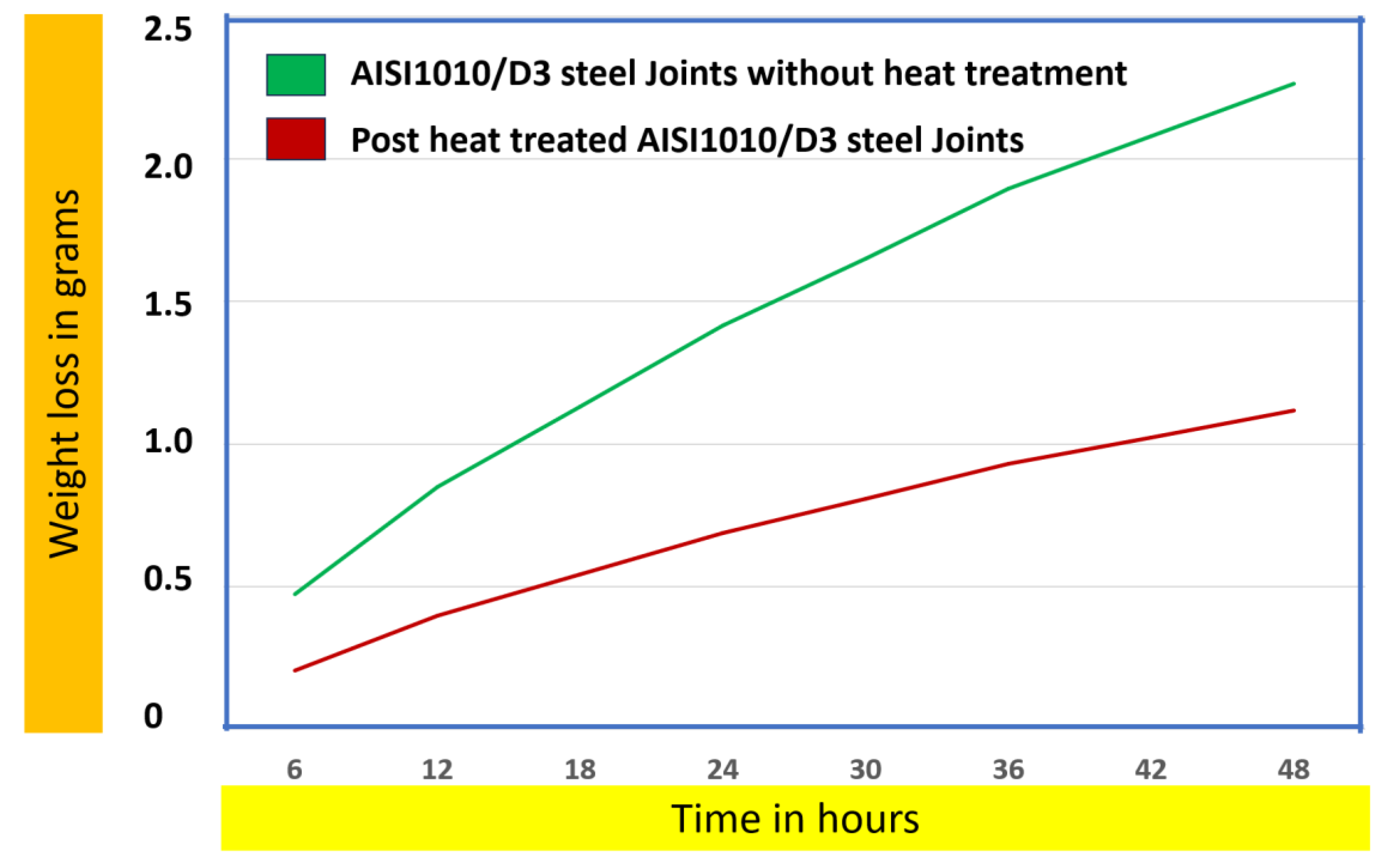
- Overall, the corrosion rate of post-weld heat-treated AISI1010/D3 steel joints was more effectively reduced by about 54.8% and the weight loss by 60%. Post-weld heat-treated AISI1010/D3 steel joints are preferable in applications where failure due to corrosion occurs.
Author Contributions
Funding
Data Availability Statement
Acknowledgments
Conflicts of Interest
References
- Maalekian, M. Friction welding—Critical assessment of literature. Sci. Technol. Weld. Join. 2007, 12, 738–759. [Google Scholar] [CrossRef]
- Sahin, M.; Misirli, C. Mechanical and metallurgical properties of friction welded aluminium joints. In Aluminium Alloys-New Trends in Fabrication and Applications; Intech: Istanbul, Turkey, 2013; Chapter 11; pp. 277–300. [Google Scholar] [CrossRef]
- Ganesan, M.; Marimuthu, P.C. Experimental Investigation of Tensile Strength Behavior on Friction Welded Austenitic Stainless Steel Grade 304L Joints. Int. J. Appl. Eng. Res. 2016, 11, 1251–1255. Available online: http://www.ripublication.com (accessed on 23 March 2022).
- Ozdemir, N.; Sarsılmaz, F.; Hascalık, A. Effect of rotational speed on the interface properties of friction-welded AISI 304L to 4340 steels. Mater Des. 2007, 28, 301–307. [Google Scholar] [CrossRef]
- Celik, S.; Ersozlu, I. Investigation of the mechanical properties and microstructure of friction welded joints between AISI 4140 and AISI 1050 steels. Mater. Des. 2009, 30, 970–976. [Google Scholar] [CrossRef]
- Wang, F.F.; Li, W.Y.; Li, J.L.; Vairis, A. Process parameter analysis of inertia friction welding nickel-based superalloy. Int. J. Adv. Manuf. Technol. 2014, 71, 1909–1918. [Google Scholar] [CrossRef]
- Kobayashi, A.; Shigematsu, I. Friction Welding Characteristics of A1070 and SUS304. In Proceedings of the 1st International Joint Symposium on Joining and Welding, Osaka, Japan, 6–8 November 2013; pp. 207–212. [Google Scholar]
- Sahin, M. Evaluation of the joint-interface properties of austenitic-stainless steels (AISI 304) joined by friction welding. Mater. Des. 2007, 28, 2244–2250. [Google Scholar] [CrossRef]
- Li, W.; Vairis, A.; Preuss, M.; Ma, T. Linear and rotary friction welding review. Int. Mater. Rev. 2016, 61, 71–100. [Google Scholar] [CrossRef]
- Selvamani, S.T.; Umanath, K.; Palanikumar, K.; Vigneswar, K.; Sivakumaar, B.T. Sensitivity analysis of friction welded AISI1035 grade carbon steel rods. In Proceedings of the 2014 International Conference on Science Engineering and Management Research, Chennai, India, 27–29 November 2014; Elsevier: Amsterdam, The Netherlands, 2014; pp. 820–826. [Google Scholar]
- Benkherbache, H.; Amroune, S.; Zaoui, M.; Mohamad, B.; Silema, M.; Saidani, H. Characterization and mechanical behaviour of similar and dissimilar parts joined by rotary friction welding. Eng. Solid. Mech. 2021, 9, 23–30. [Google Scholar] [CrossRef]
- Hascalik, A.; Unal, E.; Ozdemir, N. Fatigue behaviour of AISI 304 steel to AISI 4340 steel welded by friction welding. J. Mater. Sci. 2006, 41, 3233–3239. [Google Scholar] [CrossRef]
- Kırık, I.; Ozdemir, N. Weldability and joining characteristics of AISI 420/AISI 1020 steels using friction welding. Int. J. Mat. Res. 2013, 104, 769–775. [Google Scholar] [CrossRef]
- Mercan, S.; Aydin, S.; Ozdemir, N. Effect of welding parameters on the fatigue properties of dissimilar AISI 2205–AISI 1020 joined by friction welding. Int. J. Fatigue 2015, 81, 78–90. [Google Scholar] [CrossRef]
- Kirik, I.; Özdemýr, N. Effect of process parameters on the microstructure and mechanical properties of Friction-welded joints of AISI 1040/AISI 304L steels. Mat. Tech. 2015, 49, 825–832. [Google Scholar] [CrossRef]
- Bati, S.; Kiliç, M.; Kirik, I. Friction welding of dissimilar AISI 304 and AISI 8640 steels. Eur. J. Technol. (EJT) 2016, 6, 79–86. [Google Scholar]
- Mercan, S.; Özdemir, N. Weldability characteristics of friction-welded AISI 2205 to AISI 1020 steels. Weld. World 2017, 61, 667–677. [Google Scholar] [CrossRef]
- Dey, H.C.; Ashfaqb, M.; Bhaduria, A.K.; Rao, K.P. Joining of titanium to 304L stainless steel by friction welding. J. Mat. Proc. Technol. 2009, 209, 5862–5870. [Google Scholar] [CrossRef]
- Sathiya, P.; Aravindan, S.; Haq, A.N. Effect of friction welding parameters on mechanical and metallurgical properties of ferritic stainless steel. Int. J. Adv. Manuf. Technol. 2007, 31, 1076–1082. [Google Scholar] [CrossRef]
- Rajendran, T.P.; Hynes, N.R.J.; Christopher, T. Characterization of high-carbon high-chromium tool steel/low-carbon steel friction-welded joints for industrial tooling applications. J. Braz. Soc. Mech. Sci. Eng. 2018, 40, 316. [Google Scholar] [CrossRef]
- Emre, H.E.; Kaçar, R. Effect of post weld heat treatment process on microstructure and mechanical properties of friction welded dissimilar drill pipe. Mat. Res. 2015, 18, 503–508. [Google Scholar] [CrossRef]
- Ma, H.; Qin, G.; Geng, P.; Li, F.; Meng, X.; Fu, B. Effect of post-weld heat treatment on friction welded joint of carbon steel to stainless steel. J. Mat. Proc. Technol. 2016, 227, 24–33. [Google Scholar] [CrossRef]
- Rajendran, T.P.; Hynes, N.R.J.; Nikolova, M.P.; Christopher, T.; Nikolov, D. Influence of heat treatment on friction-welded joints made of high-carbon high chromium tool steel/low-carbon steel for tooling applications. J. Braz. Soc. Mech. Sci. Eng. 2020, 42, 87. [Google Scholar] [CrossRef]
- Ozdemir, N. Investigation of the mechanical properties of friction-welded joints between AISI 304L and AISI 4340 steel as a function rotational speed. Mat. Lett. 2005, 59, 2504–2509. [Google Scholar] [CrossRef]
- Hynes, N.R.J.; Jebaraj, D.J.J.; Selvaraj, M.; Ali, M.A.; Raza, M.H.; Pruncu, C.I.; Velu, P.S.; Vignesh, N.J. Thermal behavior analysis and mechanical characterization of friction stud welded AISI 304/AA6063 joints. J Braz. Soc. Mech. Sci. Eng. 2022, 44, 114. [Google Scholar] [CrossRef]
- Tharmaraj, R.; Hynes, N.R.J. Investigation on the thermal behavior of friction stud welding of dissimilar aluminum/mild steel joints. Surf. Rev. Lett. 2022, 29, 2250093. [Google Scholar] [CrossRef]
- Tang, T.; Shi, Q.; Lei, B.; Zhou, J.; Gao, Y.; Li, Y.; Zhang, G.; Chen, G. Transition of interfacial friction regime and its influence on thermal responses in rotary friction welding of SUS304 stainless steel: A fully coupled transient thermomechanical analysis. J. Manuf. Process. 2022, 82, 403–414. [Google Scholar]
- Hynes, N.R.J.; Velu, P.S.; Nithin, A.M. Friction push plug welding in airframe structures using Ti-6Al-4V plug. J Braz. Soc. Mech. Sci. Eng. 2018, 40, 158. [Google Scholar] [CrossRef]
- Hynes, N.R.J.; Nagaraj, P.; Sujana, J. Regression Modelling of Joining Aluminium Studs to Steel with AA 1100 Interlayer. EXP Tech 2019, 43, 491–500. [Google Scholar] [CrossRef]
- Zhao, Q.; Ma, H.; Qin, G. On the formation of interfacial compounds in the 2A14 Al alloy/steel friction welded joint: A comparative study. J. Manuf. Process. 2022, 83, 398–413. [Google Scholar]
- Hynes, N.R.J.; Velu, P.S. Effect of rotational speed on Ti-6Al-4V-AA 6061 friction welded joints. J. Manuf. Process. 2018, 32, 288–297. [Google Scholar]


| Material | C% | P% | Si% | S % | Mn% | Cr% | Fe% |
|---|---|---|---|---|---|---|---|
| Steel D3 | 2.10 | 0.03 | 0.30 | 0.03 | 0.40 | 11.50 | Remaining |
| AISI 1010 | 0.1 | 0.04 | - | 0.05 | 0.45 | - | Remaining |
| Specimen | Rotational Speed, rpm | Axial Pressure, MPa | Forging Time, s |
|---|---|---|---|
| S1 | 1600 | 0.6 | 24.6 |
| S2 | 1400 | 0.6 | 9.2 |
| S3 | 1200 | 0.6 | 10.6 |
| Zones | S1 1600 rpm | S2 1400 rpm | S3 1200 rpm | |||
|---|---|---|---|---|---|---|
| HAZ (in mm) | 10.8 | 14.8 | 19.5 | |||
| PDZ (in µm) | D3 Steel | AISI 1010 | D3 Steel | AISI 1010 | D3 Steel | AISI 1010 |
| 200 | 180 | 380 | 220 | 520 | 360 | |
| DZ (in µm) | D3 Steel | AISI 1010 | D3 Steel | AISI 1010 | D3 Steel | AISI 1010 |
| 150 | 550 | 200 | 680 | 320 | 750 | |
| Total DZ (in µm) | 700 | 880 | 1070 | |||
| FPDZ (in µm) | 48 | 220 | 380 | |||
Disclaimer/Publisher’s Note: The statements, opinions and data contained in all publications are solely those of the individual author(s) and contributor(s) and not of MDPI and/or the editor(s). MDPI and/or the editor(s) disclaim responsibility for any injury to people or property resulting from any ideas, methods, instructions or products referred to in the content. |
© 2025 by the authors. Licensee MDPI, Basel, Switzerland. This article is an open access article distributed under the terms and conditions of the Creative Commons Attribution (CC BY) license (https://creativecommons.org/licenses/by/4.0/).
Share and Cite
Navasingh, R.J.H.; Rajendran, T.P.; Nikolova, M.P.; Goldin Priscilla, C.P.; Niesłony, P.; Żak, K. Improved Microstructure Evolution and Corrosion Resistance in Friction-Welded Dissimilar AISI 1010/D3 Steel Joints Through Post-Weld Heat Treatment. J. Manuf. Mater. Process. 2025, 9, 124. https://doi.org/10.3390/jmmp9040124
Navasingh RJH, Rajendran TP, Nikolova MP, Goldin Priscilla CP, Niesłony P, Żak K. Improved Microstructure Evolution and Corrosion Resistance in Friction-Welded Dissimilar AISI 1010/D3 Steel Joints Through Post-Weld Heat Treatment. Journal of Manufacturing and Materials Processing. 2025; 9(4):124. https://doi.org/10.3390/jmmp9040124
Chicago/Turabian StyleNavasingh, Rajesh Jesudoss Hynes, T. Packiaraj Rajendran, Maria P. Nikolova, C P Goldin Priscilla, Piotr Niesłony, and Krzysztof Żak. 2025. "Improved Microstructure Evolution and Corrosion Resistance in Friction-Welded Dissimilar AISI 1010/D3 Steel Joints Through Post-Weld Heat Treatment" Journal of Manufacturing and Materials Processing 9, no. 4: 124. https://doi.org/10.3390/jmmp9040124
APA StyleNavasingh, R. J. H., Rajendran, T. P., Nikolova, M. P., Goldin Priscilla, C. P., Niesłony, P., & Żak, K. (2025). Improved Microstructure Evolution and Corrosion Resistance in Friction-Welded Dissimilar AISI 1010/D3 Steel Joints Through Post-Weld Heat Treatment. Journal of Manufacturing and Materials Processing, 9(4), 124. https://doi.org/10.3390/jmmp9040124