Article

Aluminium/Steel Joints with Dissimilar Thicknesses: Enhancement of UTS and Ductility Through Making an S-Shaped Interface and a Mixed-Mode Fracture

by
Tiago Oliveira Gonçalves Teixeira
1,
Reza Beygi
2,*,
Ricardo João Camilo Carbas
3,
Eduardo Andre Sousa Marques
1,
Masih Bolhasani Hesari
2,
Mohammad Mehdi Kasaei
3 and
Lucas Filipe Martins da Silva
1
1
Department of Mechanical Engineering, Faculty of Engineering of the University of Porto, Rua Dr. Roberto Frias, 4200-465 Porto, Portugal
2
Department of Materials Engineering and Metallurgy, Faculty of Engineering, Arak University, Arak 38156-8-8349, Iran
3
Institute of Science and Innovation in Mechanical and Industrial Engineering (INEGI), Rua Dr. Roberto Frias, 4200-465 Porto, Portugal
*
Author to whom correspondence should be addressed.
J. Manuf. Mater. Process. 2025, 9(4), 120; https://doi.org/10.3390/jmmp9040120
Submission received: 25 February 2025 / Revised: 15 March 2025 / Accepted: 27 March 2025 / Published: 5 April 2025
(This article belongs to the Special Issue Advances in Dissimilar Metal Joining and Welding)

Abstract

This study presents a simple and innovative design to join a 2 mm thick steel sheet to a 5 mm thick aluminium sheet in a butt configuration. Thickness differences were addressed using support plates, while an aluminium run-on plate was employed to prevent the FSW tool from plunging into the steel. The process produced a unique S-shaped Al/St interface, the formation mechanism of which is analysed in this study. Scanning electron microscopy (SEM) observations revealed a gradient in the thickness of intermetallic compounds (IMCs) along the joint interface, decreasing from the top to the bottom. This S-shaped interface led to a 150% increase in the ultimate tensile strength (UTS) of the joint. The mechanism underlying this enhancement, attributed to the curved geometry of the interface and its alignment with the loading direction, is discussed in detail. These findings highlight the potential of this approach for improving the performance of dissimilar material joints in lightweight structural applications.

1. Introduction

Over the last few years, the automotive industry has invested time and resources with the objective of finding lightweight alternatives for their structural components, replacing the widely used steel (St) for aluminium (Al) and other high strength-to-weight alloys [1], as well as transitioning to greener and more energetic efficient technologies. The friction stir welding (FSW) joining process enables a solid-state weld (SSW) between two distinct metals, by means of a non-consumable rotating tool, responsible for generating the heat necessary by friction with the substrates, bringing them to a state of plasticity, allowing the two to stir and mix, resulting in a weld. Welding two dissimilar metals would not be possible with conventional fusion processes, with the additional advantage of having a low energetic cost and being environmentally friendly, without the necessity of flux or cover gas while welding the two metals [2,3]. Joining dissimilar materials often requires accommodating differences in thickness to ensure their effective application in the transportation industry. Friction stir welding (FSW) has proven to be an effective process for joining materials such as aluminium (Al) and steel (St). In butt configuration, both material dissimilarities and thickness differences pose significant challenges to achieving a high-quality joint.
The FSW of dissimilar metals, with focus on the present Al/St joints, does not come without its particular challenges, above all the inherent thermal properties differences between these two materials. The most significant hardships of welding aluminium and steel is dissimilar thermal conductivity, challenging a uniform temperature distribution during the FSW process, together with the dissimilar melting points, requiring precise control of the manufacturing parameters to avoid defects caused by inadequate heating of either material [4]. Additionally, the dissimilarities in hardness and deformation characteristics also contribute to uneven material flow, necessitating heedful tool design and process optimisation [5].
Yet another major challenge to dissimilar metal welding, in particular Al/St, is the formation of hard and brittle Al-Fe intermetallic compounds (IMCs) at the interface, resulting in inferior mechanical properties of the joint, reducing its overall structural reliability [6]. The formation of IMCs is promoted by the high friction temperatures reached in the FSW process [7], along with the stirring of the two metals, facilitating the diffusion of Al and Fe elements across the interface of the joint and the consequent solid-state reaction of the atoms, leading to the nucleation and further growth of IMCs along the bonded interface [8]. Before IMCs formation and below a critical thickness of transition layer, an amorphous structure is formed which possess higher toughness than Al-Fe IMCs [9]. However, this approach is applied in lap configuration and requires very precise control of the tool position.
A reasonable number of joint designs can be obtained by FSW of dissimilar metals, in similar fashion to the simplest configurations obtained in the conventional welding technologies [10]. Dissimilar metal joining by FSW is already successfully used in the automotive industry and has been for more than a decade, with special regard to Honda, which implemented this technology to their 2013 Accord model, in a structural component, welding the front steel sub-frame to the aluminium base in a lap joint configuration [11,12]. From previous works [13], it is known that welding substrates of dissimilar thicknesses in butt configuration comes with additional technical challenges to those already mentioned. A TIG-assisted FSW was used to join Al/St with dissimilar thicknesses by offsetting the tool into Al [14]. This approach, while facilitating the process, creates difficulties in terms of the thick IMC layer at the interface. The key for establishing metallurgical bonding is the contact of the pin with steel while the pin is offset to Al [15]. This approach is difficult when using conventional tools made of steel due to wearing of the tool. The highest temperature during welding exists in the periphery of the pin where the metallurgical bonding is formed between Al and St, which enhances the IMCs rapid growth [8]. A contactless approach was used to join Al to St by choosing a thickness difference between the two sheets, achieving a strength of 104 MPa [16]. This strength was obtained between Al and stainless steel, which, as previously reported, has a higher strength than Al/carbon steel joints due to lower thicknesses of IMCs layer in Al/stainless steel joints [17]. This means lower strength values will be obtained when welding Al to carbon steel by this approach.
The present research strives to develop a novel FSW design to address the challenges of different thickness. So, a new joint configuration was used to facilitate FSW of dissimilar thickness of the Al and St substrates (5 mm-thick AL1050 to 2 mm-thick St37 carbon steel). For doing so, extra sheets were used to accommodate the thickness differences. Also, a run-on-plate was used to avoid direct plunging of the FSW tool into steel in when beginning the welding. The unique interface obtained by this approach was analysed by scanning electron microscopy (SEM) and energy-dispersive spectroscopy (EDS) to study the IMCs layer from top to the bottom of the joint. The contribution of IMCs as well as the shape of the interface on the fracture behaviour of the joint and enhancement of UTS and ductility was elaborated. The main outcome of the present study is to investigate how this new S-shaped interface contributes to the failure of dissimilar joints with regards to the IMCs layer at the interface.

2. Experimental Procedure

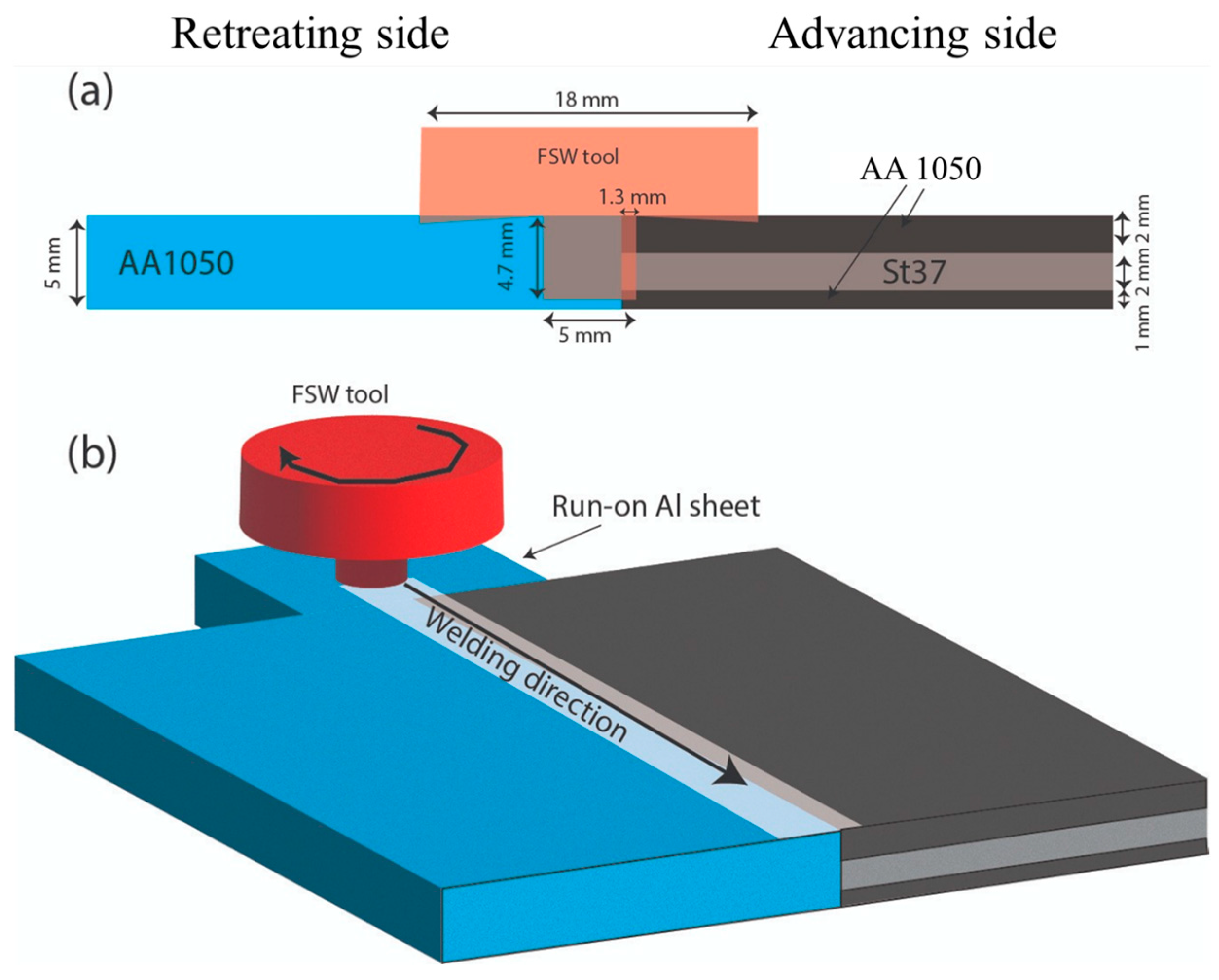
2.1. Joint Manufacturing

Two substrates, Al1050 and St37, with 5 mm and 2 mm plate thickness respectively, were used to be joined by FSW. Table 1 shows the chemical composition and mechanical properties of all the pieces. Figure 1a shows the detail of the joint design used. Taking into account the difference in the substrate’s thicknesses, AA1050 were used in the top and bottom part of the manufacturing apparatus, with 2 mm and 1 mm plate thickness, respectively, in order to accommodate the potential gaps. Other alternatives for this thickness accommodation (for instance 1.5 mm at the top and 1.5 mm at the bottom) will be considered in future works. The FSW tool was made of H13 tool steel with the dimensions seen in Figure 1a. The machined tool was heat treated (austenitized at 1030 °C, quenched in air, and tempered at 550 °C) to obtain the desired hardness and strength. Tool offset is an important parameter for FSW of Al to St [18]. An offset of 1.3 mm to St was used for two reasons: first, to make sure that there the tool makes contact with St and second, to make a material flow in St to extend the joint interface. An Al run-on-plate was used to avoid plunging the tool into St in the beginning of the weld (Figure 1b). Without this run-on-plate, a part of the pin of FSW would plunge into St in a cold state, which could break the pin. This run-on-plate helps to warm up the plates and make a steady state condition which creates a steady material flow pattern around the tool before reaching Al/St interface [19]. After welding, the base materials and the top and bottom support plates were separated. Later, we discuss why these support plates were removed easily.

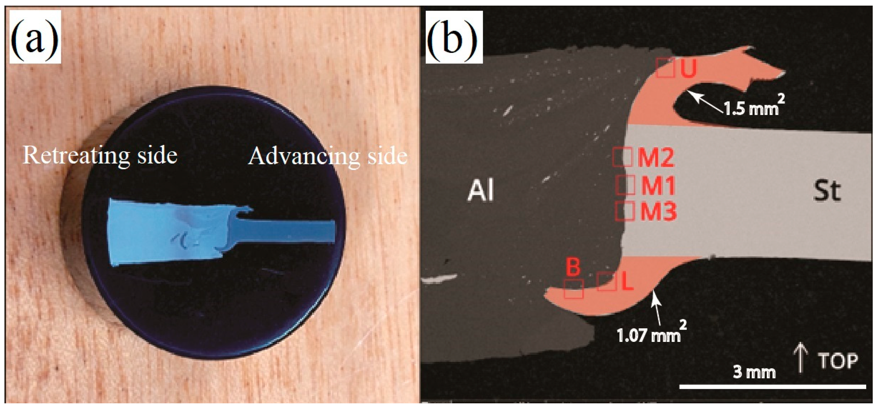
2.2. SEM/EDS Analysis

The cross-section of the joint was mounted in resin, as shown in Figure 2a. SEM/EDS examination was carried out using a high-resolution scanning electron microscope with X-ray microanalysis and analysis of backscattered electron (BSE) patterns: FEI Quanta 400FEG ESEM/ EDAX Genesis X4M. The samples were coated with Au/Pd thin films by sputtering using the SPI Module Sputter Coater. The macroscopic SEM image of the cross-section is shown in Figure 2b. The interface is S-shaped, indicating that steel was pushed to the AS at top and pushed to RS at the bottom. Fragments of steel are also seen in the stir zone of Al. The areas of steel flown to top and bottom were calculated to be 1.5 and 1.07 mm2, respectively, (red areas in Figure 2b). The total area is therefore 2.57 mm2, which is a bit lower than the area of pin offset to steel (1.3 mm of pin offset × 2 mm thickness of steel = 2.6 mm2). This is due to partial fragmentation of steel and its dispersion in the matrix of Al.
Due to existence of different conditions in various locations of the weld interface, several points were selected to be studied by SEM. The first motivation for this was to measure the thickness of the IMCs layer at each point. At this session, 6 zones were studied, observed in Figure 2b:
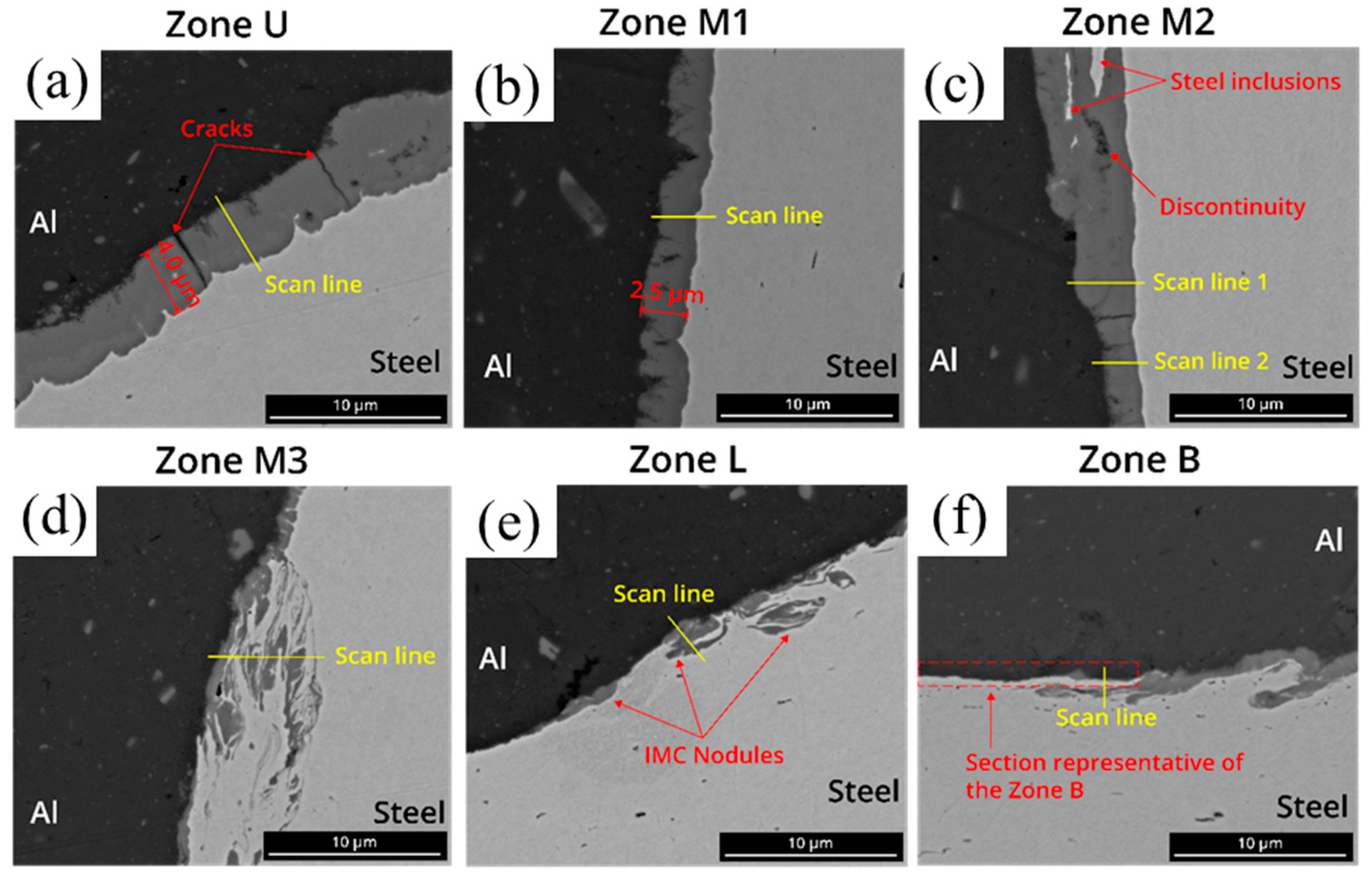
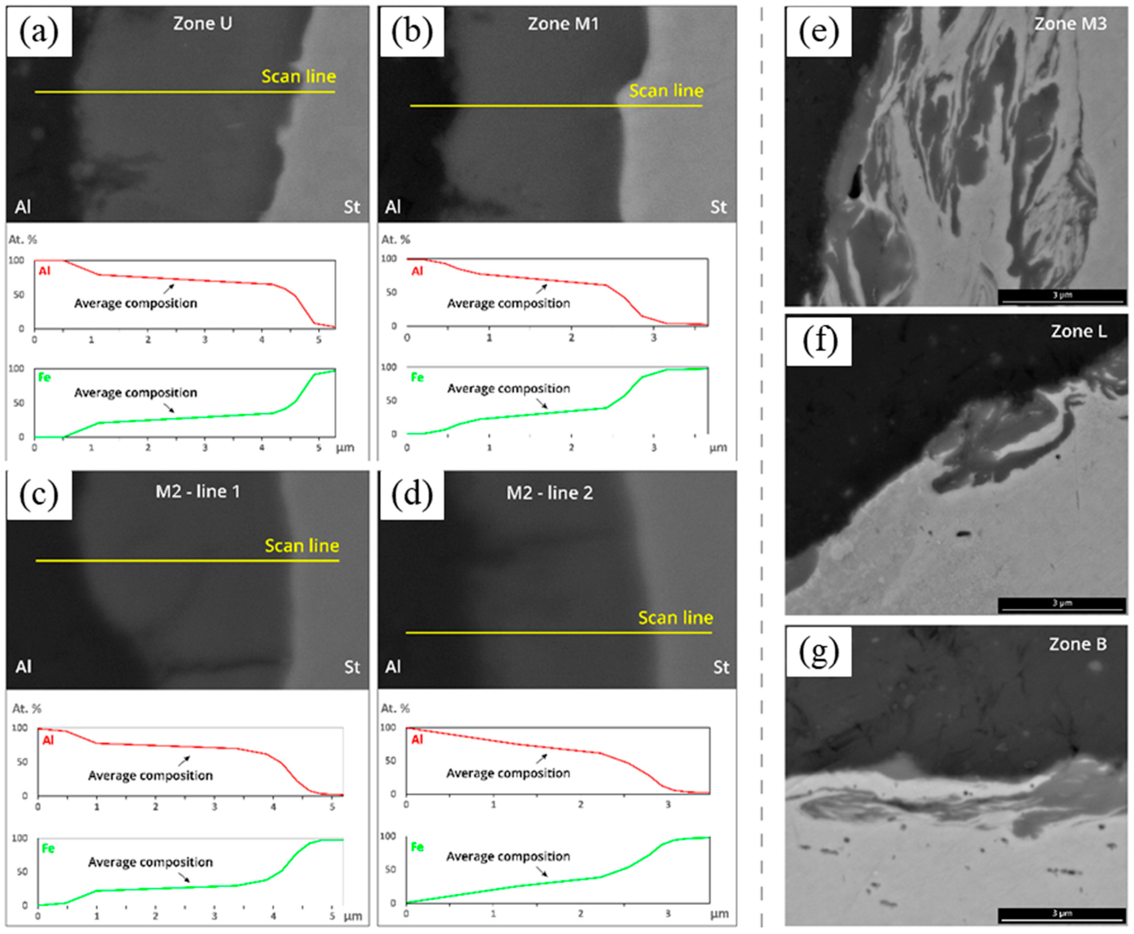
  • U—upper part of the interface;
  • M1, M2, and M3—middle part of the interface;
  • L—lower tip of the interface;
  • B—bottom part of the interface.
For each zone, images were taken, ranging from 1000× up to 30,000× magnification, as well as EDS line scans, enabling us to analyse the atomic percentage of Al and Fe of the interface. All post-processing of the images and the consequent measurements were performed in ImageJ software version 1.53e.

2.3. Mechanical Tests and Fractography

With the aim of testing the mechanical properties fabricated welds, 5 mm-wide specimens were machined by wire electrical discharge machining (WEDM), in order to avoid any unwanted influences of high machining temperatures that could result in the change of the IMC microstructure formed during the welding process and lead to misleading results. Tensile testing was performed at the crosshead speed of 1 mm/min. The fracture surfaces then were studied by SEM to investigate the fracture mechanism.

2.4. TEM and EBSD Analyses

The focus of TEM analysis in the present study was put on steel to study the grain morphology in its thermo-mechanically affected zone (TMAZ). This helped to explain the hardness profile observed in this part of steel, which is located adjacent to the weld interface. The analysis of IMCs by TEM was not reported in this study, as a thorough analysis of IMCs has already been provided in our previous paper [20].
Electron backscatter diffraction (EBSD) analysis was carried out from the stir zone of Al to investigate grain morphology and recrystallization. The samples were surface treated before EBSD by chemical polishing with Colloidal Silica. The step size of EBSD has been chosen to detect grain sizes below 50 nm.

3. Results and Discussion

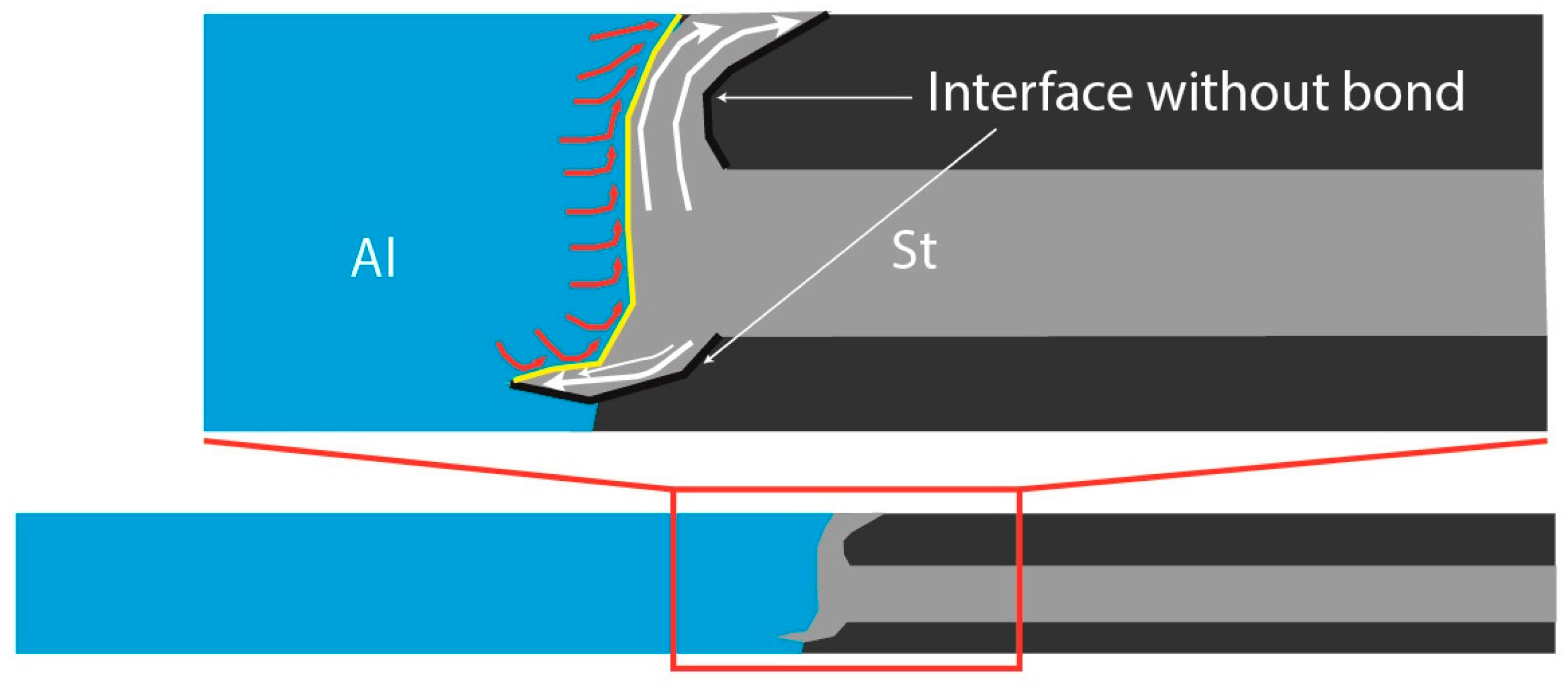
3.1. Joint Geometry and Interface Microstructure

As mentioned in the previous section, a weld with dissimilar thickness was manufactured, resulting in the join geometry seen in Figure 2, where the image upper part coincides with the top side of the weld: a noticeable S-shaped joint cross-section geometry, with the upper tip facing the steel substrate and the lower one facing the aluminium substrate. This phenomenon is attributed to the material flow during the solid-state welding, characteristic of FSW. The schematic of material flow is shown in Figure 3. In the steel side of the joint, the advancing tool velocity and the rotation velocity are in concordance, having the same direction in the advancing side (AS) of the weld, while in the aluminium side, these two velocities have an opposite direction in the retreating side (RS) of the weld, resulting in an asymmetry in the flow of the two materials, being in a plastic regime, and therefore an asymmetry in the microstructure of the joint after cooling [21]. The high hydrostatic pressure applied at the top side of the joint by the shoulder of the tool causes a displacement of the plasticised material from the tool outwards, leading to the observed unique upper tip of the S-shape. At the bottom of the tool’s pin, there is a swirl motion caused by the asymmetric flow of the plasticised material, generating rotation and translation of the materials from the advancing side to the retreating side of the joint [22], resulting in the penetration of St in the Al substrate. Also, it is possible to observe, at the bottom side of the joint, an aluminium tip, with an approximate thickness of 0.6 mm, where no weld is present, and thus no IMCs are formed. The steel, which flows upward, has no bonding to the support plates in the right side (advancing side). This is because this region is out of the stirring zone on the tool. This pattern of flow of steel, which was pushed to the advancing side at top and pushed to the retreating side in the bottom, was facilitated by using soft sheets as support plates. Steel could penetrate these supports easily due to the low flow strength of the supports. Also, the run-on-plate in the beginning of the weld helped to facilitate the material flow around the pin and heat production to reach a steady state condition early before the pin reaches the Al/St interface. After the tool begins to traverse along the weld seam, where the pin reaches the Al/St interface the material is hot enough to facilitate the material flow of steel around the rotating pin.
The IMC layer formed as result of the weld, is not uniform along the interface of the joint, varying from thickness, morphology, and microstructure. At the top to middle zones of the joint, seen in Figure 4a–d, we have a homogenous layer, yet with a considerable number of cracks and discontinuities along these zones. Additionally, some occasional inclusions of steel are present at the interface surrounded by the IMC layer, as shown at zone M2, Figure 4c, a consequence of the stirring motion caused by the rotating motion of the tool, and zones of irregular highly irregular IMC growth and further morphology can be seen, likewise in zone M3, Figure 4d. However, this is not the case at the lower zones of the joint interface, where an intermittent morphology of IMC appears along the zone, consisting in some sections of lower thickness and other sections with the occurrence of irregular IMC nodules and sporadic short thicker sections, observed in the zones L and B, Figure 4e,f, being eventuality of an already rough surface of the metal substrates. Furthermore, only small particles of steel appear dispersed in the Al matrix along all the interface of the weld, which diminish the potential for compromising the weld integrity, in contrast with larger fragments that might occur in these types of joints [23].
In Figure 4, the EDS line-scans locations are highlighted, presenting a chemical composition across the interface of the weld. By analysing the results of the EDS line-scans performed at all the seven locations, zone U, zone M1, and zone M2 display a linear average atomic percentage (at. %) of Al and Fe at the centre of the IMC layer, as shown in Figure 5a–d. For the upper zone U and middles zones M1 and M2 at the scan line 1, the IMC layer exhibits 70–72% Al at. %, representing an Fe2Al5 IMC phase [24]. This Al-Fe phase is characterised as being brittle and having a low ductility, compared with other phases, resulting in less-than-desirable joint integrity [7]. Furthermore, the lower ductility of Fe2Al5 compounds can lead to the formation of cracks along the IMC layer of the bonded joint [25]. The second EDS line-scan performed of the zone M2 presents an Al at % between 62–78%, leading to an unconclusive phase present at this section. Due to the non-linear and varying chemical content of the zones M3, L, and B (Figure 5e–g respectably), correlated with the complex microstructure, the Al-Fe IMCs present at these sections require further analysis to determine the corresponding phases. A special feature of IMC layers at locations L and B is their nonuniform distribution as well as their very low thickness in some regions of the interface, ranging from 100 to 500 nm.
A TEM image of steel close to the interface is provided in Figure 6. Some elongated ferrite grains are visible in this figure. The grains are not uniform in terms of size which indicates the absence of dynamic recrystallization structure. This means that steel was not in the stir zone during FSW process. In fact, 1.3 mm of offset of the tool into steel caused a major part of steel to be pushed upward and downward, causing steel to be out of the stirring action of the tool (Figure 2b) and a slight portion to be fragmented and dispersed into the Al matrix. The presence of some small grains may indicate a partial recrystallization, as shown in Figure 6.
Figure 7a shows EBSD image of the stir zone of Al. Figure 7b shows the pole figures of 011 and 111 planes. During FSW process, shear deformation and recrystallization occur. A < 111 > fibre texture is observed in the stir zone. The distribution of misorientation angle is presented in Figure 7c. A small fraction (about 15%) of boundaries are of low angle grain boundary (LAGB) type, indicating a high degree of dynamic recrystallization. Grain size distribution is shown in Figure 7d. The grains in the stir zone of Al are smaller than 1 µm. Figure 7e shows the local orientation spread. As can be observed, more than 95% of the area has misorientation less than 2°, indicating a full recrystallization.

3.2. IMC Layer Thicknesses

The IMC layer thicknesses were measured in the previously mentioned zones—U, M1, L, and B—while taking into account the homogeneous thickness zones of the layer and ignoring existing nodules and sections with Al or St inclusions in the IMC layer that could influence erratic measurements. These sections are present in zones M2, M3, and L, observed in Figure 4c–e, respectively. Furthermore, the section representative of Zone B, and where the measurements were taken, is indicated in Figure 4f.
The thicknesses of the IMC layer at Zones U, M1, L, and B (Figure 8) vary from the upper part of the interface to the bottom, in a decreasing order. The temperature has an influence in the growth of IMCs [17], increasing the diffusion rate of Al and Fe atoms and consequently forming thicker layers of IMC [7]. The shoulder of the FSW tool provides, among other functions, the necessary friction and consequent heat source for the substrates to reach high temperatures, achieving a plastic regime and forming a welded joint. These temperatures are much higher in the top part of the joint compared to the bottom part, correlating to the distance from the heating source, resulting in a gradient of temperatures along the FSW process [26]. This phenomenon explains the thicknesses gradient along the IMC layer seen in the joints present in this work. Fick’s diffusion rules govern the diffusion rates, which are highly temperature dependent. For higher temperature, the diffusion coefficient rises correspondingly, increasing atomic mobility and allowing for rapid diffusion of aluminium and iron atoms into each other’s crystalline structures, thus increasing the total diffusion process, and facilitating the kinetics of the reaction between Al and Fe atoms, leading to a higher growth of the IMC at the interface of the base metals [27]. Since the peak temperatures reached during the welding process are higher at the top side of the joint, the IMC layer thickness is also higher in the zones, following the same correlation for the decreasing peak temperatures reached along the interface. The bottom of the weld is furthest region from the shoulder, being less influenced by the heat of the shoulder and thus having the lowest thickness of IMC layer.

3.3. Microhardness Analysis

The hardness profiles along three lines taken from upper, middle, and bottom section of the joint interface are shown in Figure 9. The hardness of the base materials of Al and St are 35 and 116, respectively. As clear from the yellow region in Figure 9, in St near to the joint interface, the hardness increases up to 175 HV. It is noted that this region is not in the stir zone and is only influenced by the material flow pattern shown in Figure 3. This region is TMAZ, where plastic deformation occurred without full recrystallization. The grains in this region are elongated in the direction of material flow, as can be seen in Figure 6. An increase in hardness of Al from 35 HV to 44 HV is observed in the stir zone (blue region). This increase is observed in upper and middle sections (lines U and M), the former being extended to 6 mm and the latter to 4 mm away from the interface. No increase in hardness was observed in the bottom section (Line B). This can be realised by matching the pin with the weld cross-section. Lines U and M are in the stir zone, while line B is under the pin. The increase of hardness in the stir zone is due to grain refinement as well as the dispersion of St fragments. These two factors are absent under the pin and hence no increase in hardness was observed in line B. Figure 9c clearly shows that no St fragments are observed under the pin, indicating that this region was not influenced by the stirring action of the pin.

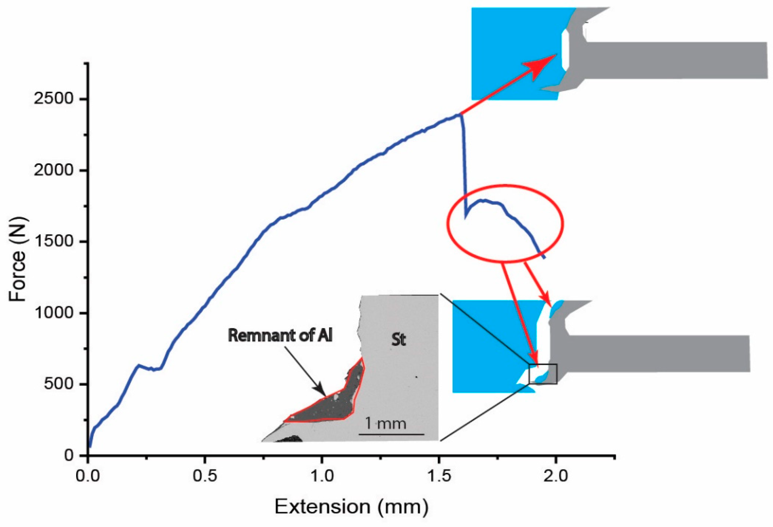
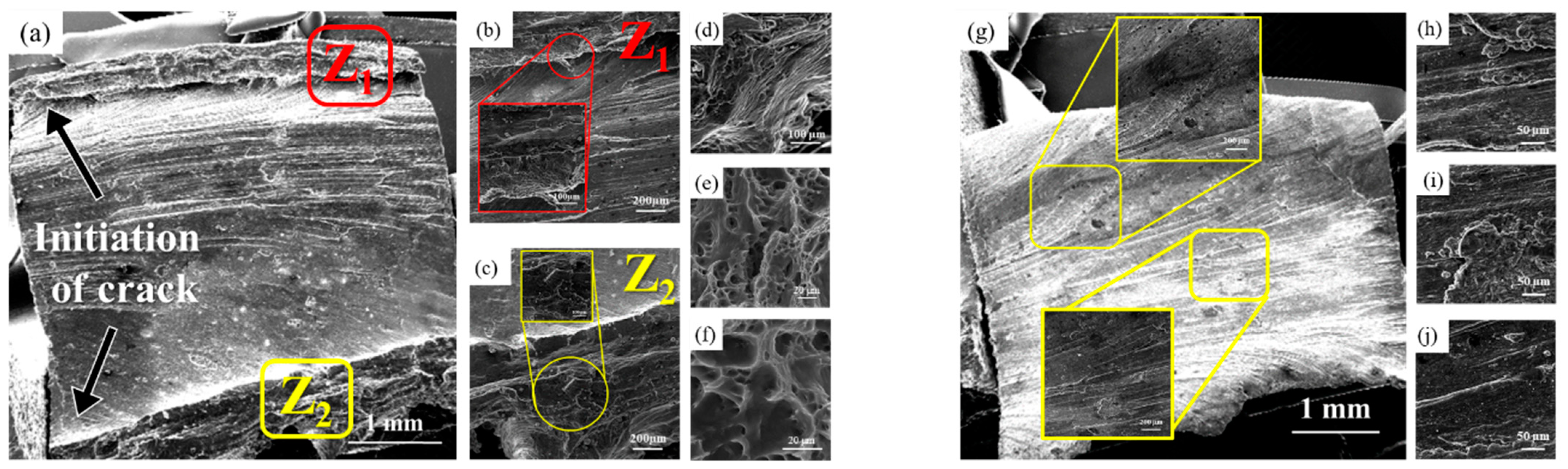
3.4. Mechanical Properties and Fracture Behaviour

The load–displacement curve of the sample during tensile test is shown in Figure 10. The tensile force is 2500 N, which is equivalent to a UTS of 250 MPa considering steel with a thickness of 2 mm. The UTS of the Al/St joints while having a flat interface totally perpendicular to the welding direction was reported to be between 80–100 MPa [28]. This scatter of the results was due to different notches considered for the tensile tests which resulted in slightly different fracture loads. In the present study, the fracture during tensile test was captured by a high-speed camera to record the fracture stages. As can be seen in Figure 10, an abrupt drop in the peak force is observed which was attributed to the low-ductility fracture in the interface perpendicular to the loading direction. A second stage with a smooth fracture path corresponded to the fracture of the upper and lower parts of the joint, where an out-of-thickness bonding was observed due to steel flow. This region failed in with regards to ductility, displaying only some ductility. Fracture in this region occurred almost from the Al base material, leaving Al remnants on the interface of steel. As evidence of this, an SEM image in BSE mode taken from the cross-section of the failed tensile specimen shows an inset in the tensile curve. Al remnants are clearly observed on the surface of St in the lower part of the joint.
Figure 11 presents SEM images from the fracture surfaces taken from both sides of Al (a–f) and St (g–j). While the middle of the interface in both sides failed for being brittle, the upper and lower parts of the joint show dimple characteristics (Figure 11d–f). This is in compliance with what was observed in Figure 10, where a remnant of Al was observed on the fracture surface of steel in the bottom of the weld. Regarding the upper part of the joint, where the thickness of IMC is highest, the failure mode in this region was a mixture of brittle and ductile modes (region Z1 shown in Figure 11d), though ductile failure was prevalent. The occurrence of ductile fracture at the upper part, despite a thick IMC layer, is attributed to the loading condition at the interface. As this part is curved, there is a shear load at the interface of this part. The interfaces are more resistant to failure when loading in shear and therefore ductile fracture occurred. In other words, IMC thickness plays a critical role in fracture when the interface is loaded in tension, while its contribution to crack initiation and propagation is not critical when loaded in shear.
The S-shaped interface, which is a result of choosing proper tool offset, run-on-plate, and using support plates, is a distinguishing characteristic of the FSW joint obtained in this study. The unique feature of this interface is that a portion of it is not perpendicular to the loading direction (at top and bottom) and hence a higher strength and ductility was obtained in comparison to the joints made by conventional FSW. Table 2 represents some data of joint strength between Al/St joints made by FSW. As can be seen, an increase of 150% in UTS was achieved by the present approach. This result is in compliance with the observations obtained by studying the fracture surface in micro scale [20]; when the joint interface is inclined with respect to the loading direction, the joint fails in a ducile mode.

4. Conclusions

A novel approach for welding dissimilar materials of varying thicknesses—5 mm-thick Al1050 and 2 mm-thick St37—was successfully applied in this study, achieving a solid-state weld between the two base metals. This yielded the following findings:
  • The process produced a unique S-shaped interface between aluminium and steel, facilitated by the use of a run-on plate and support plates.
  • This S-shaped interface enhanced the joint’s ultimate tensile strength (UTS) by 150% and improved its ductility. The curvature of the interface prevented it from being entirely perpendicular to the loading direction, contributing to better mechanical performance.
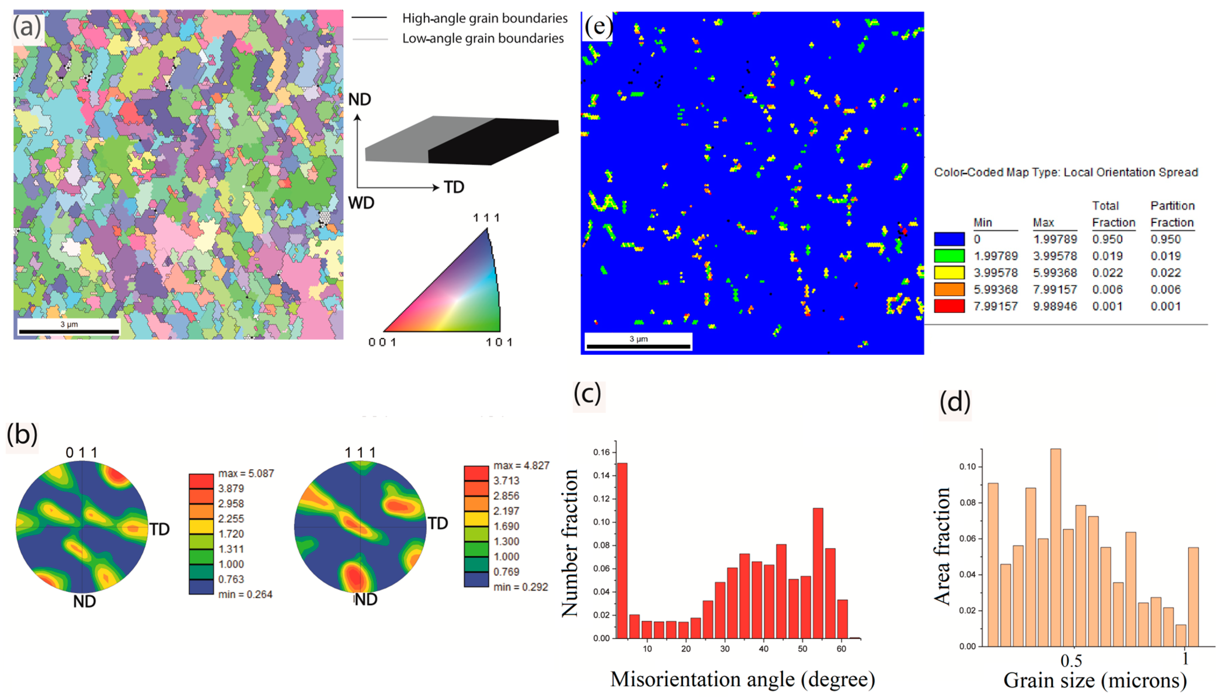
  • According to EBSD results, the stir zone of Al consists of fine grains (below 1 µm) with a B-fibre texture, indicating a strong shear deformation and dynamic recrystallization.
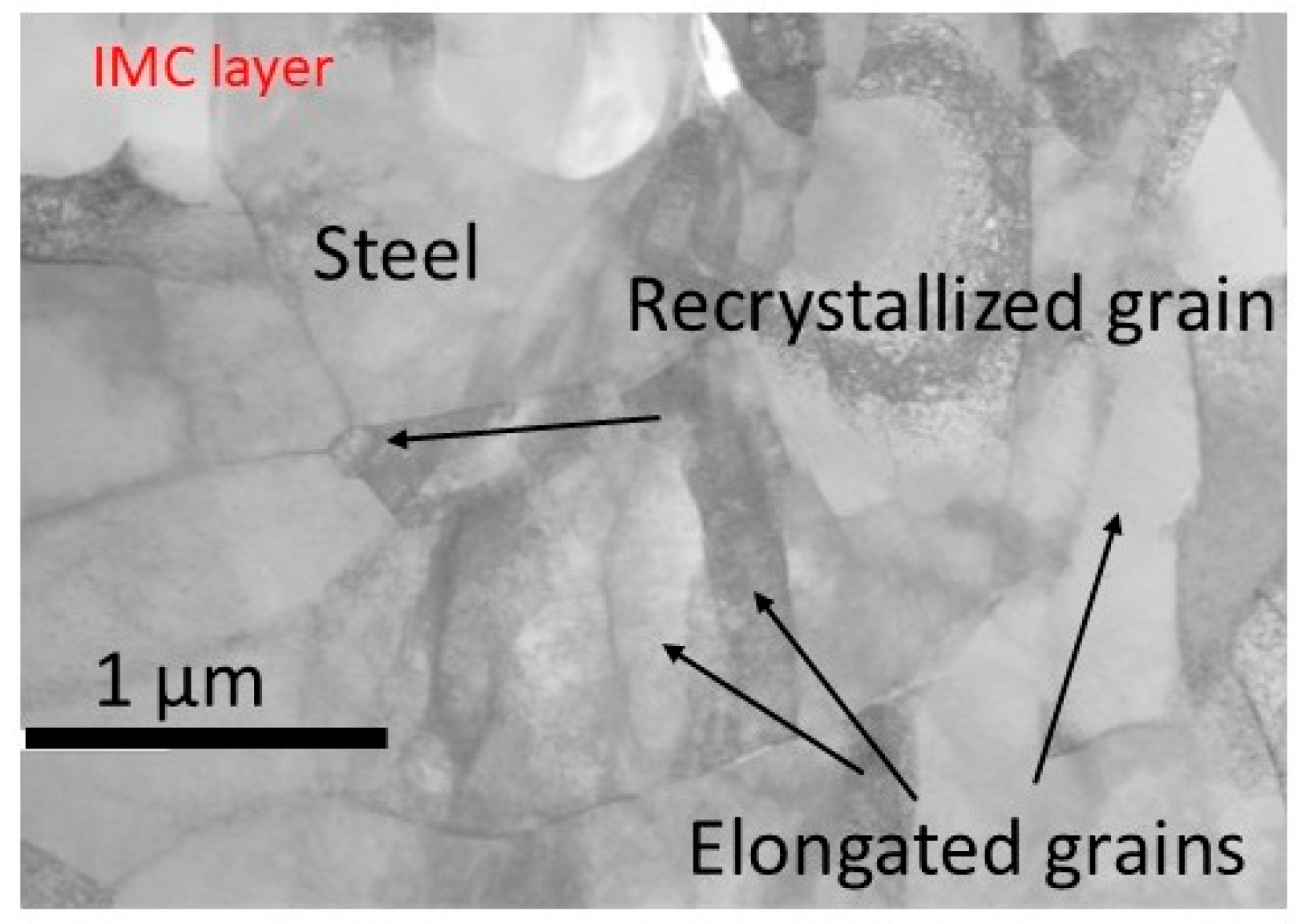
  • According to TEM images, St was not in the stir zone due to the absence of recrystallized and equiaxed grains. St in the vicinity of the interface is deformed plastically, causing the grains to be elongated in this region, with some evidence of partial recrystallization.
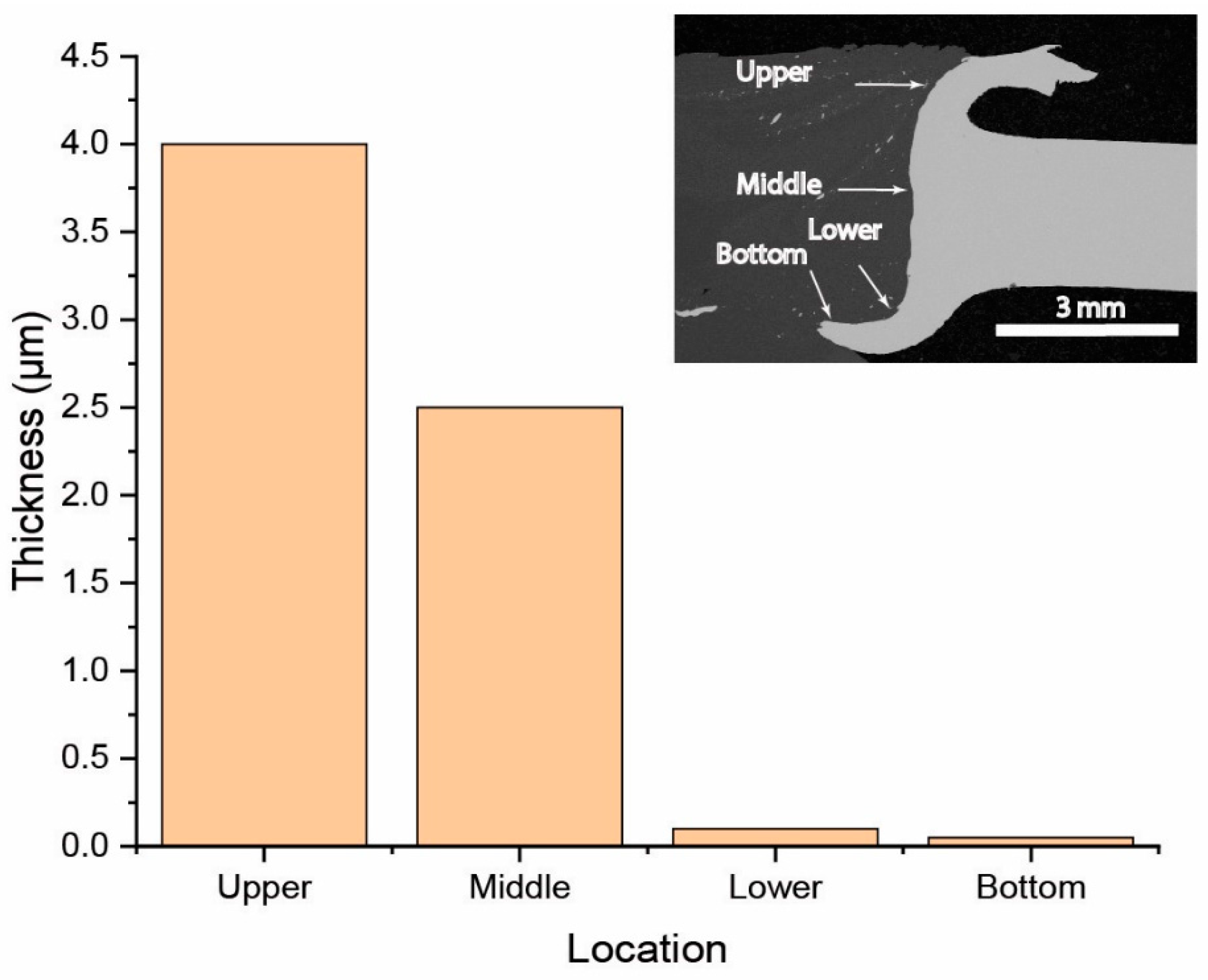
  • The weld exhibited a varying intermetallic compound (IMC) microstructure along the joint interface, with a gradient in IMC layer thickness. The thickness decreased from 4 µm at the top of the interface to 2.5 µm in the middle and less than 0.1 µm at the bottom. This gradient corresponded to the peak temperatures experienced during the welding process along the interface.
  • Tensile testing revealed that failure occurred through the IMC layers in a brittle manner at the middle section, where the interface was perpendicular to the loading direction. Conversely, at the curved sections of the interface (top and bottom), failure was ductile, leaving aluminium remnants on the steel surface.
  • IMC thickness plays a critical role in lowering the joint strength when the interface is loaded in tension. However, the IMC thickness is not decisive in the joint strength when the interface is loaded in shear.
These findings demonstrate the potential of the proposed welding approach to enhance the mechanical performance of dissimilar joints through interface geometry.

Author Contributions

Conceptualization, R.B. and L.F.M.d.S.; Methodology, T.O.G.T. and E.A.S.M. and R.J.C.C.; Validation, T.O.G.T., E.A.S.M. and R.J.C.C.; Formal Analysis, M.B.H. and T.O.G.T.; Investigation, T.O.G.T., M.B.H. and R.B.; Resources, E.A.S.M., R.J.C.C. and M.M.K.; Data Curation, M.B.H. and T.O.G.T.; Writing—Original Draft Preparation, T.O.G.T.; Writing—Review & Editing, R.B., M.B.H., E.A.S.M., R.J.C.C., M.M.K. and L.F.M.d.S.; Visualization, R.B., E.A.S.M. and R.J.C.C.; Supervision, R.B., E.A.S.M. and L.F.M.d.S. All authors have read and agreed to the published version of the manuscript.

Funding

This research received no external funding.

Data Availability Statement

Data is contained within the article.

Acknowledgments

The authors thank Arak University for supporting this project. The authors also gratefully acknowledge the Portuguese Foundation for Science and Technology (FCT) for supporting the work presented here through the individual grant’s CEECIND/02752/2018, CEECIND/03276/2018 and the funding under the reference “UIDP/50022/2020—LAETA—Laboratorio Associado de Energia, Transportes e Aeronautica”.

Conflicts of Interest

The authors declare no conflict of interest.

References

  1. Zhao, H.; Zhang, R.; Bin, Z. A Review of Automotive Lightweight Technology. In Proceedings of the 2018 International Conference on Mechanical, Electronic, Control and Automation Engineering (MECAE 2018), Qingdao, China, 30–31 March 2018; pp. 59–62. [Google Scholar]
  2. Kaushik, P.; Dwivedi, D.K. Al-steel dissimilar joining: Challenges and opportunities. Mater. Today: Proc. 2022, 62, 6884–6899. [Google Scholar] [CrossRef]
  3. Shravan, C.; Radhika, N.; Kumar, N.D.; Sivasailam, B. A review on welding techniques: Properties, characterisations and engineering applications. Adv. Mater. Process. Technol. 2023, 10, 1126–1181. [Google Scholar]
  4. Kumar, N.; Yuan, W.; Mishra, R. Challenges and opportunities for friction stir welding of dissimilar alloys and materials (Chapter 7). In Friction Stir Welding of Dissimilar Alloys and Materials; Elsevier Butterworth-Heinemann: Oxford, UK, 2015; pp. 123–126. [Google Scholar]
  5. Christy, J.V.; Mourad, A.-H.I.; Sherif, M.M.; Shivamurthy, B. Review of recent trends in friction stir welding process of aluminum alloys and aluminum metal matrix composites. Trans. Nonferrous Met. Soc. China 2021, 31, 3281–3309. [Google Scholar] [CrossRef]
  6. Zhang, X.; Gao, K.; Wang, Z.; Hu, X.; Liu, H.; Nie, Z. Effect of intermetallic compounds on interfacial bonding of Al/Fe composites. Mater. Lett. 2023, 333, 133597. [Google Scholar] [CrossRef]
  7. Wang, T.; Sidhar, H.; Mishra, R.S.; Hovanski, Y.; Upadhyay, P.; Carlson, B. Evaluation of intermetallic compound layer at aluminum/steel interface joined by friction stir scribe technology. Mater. Des. 2019, 174, 107795. [Google Scholar]
  8. Tanaka, T.; Nezu, M.; Uchida, S.; Hirata, T. Mechanism of intermetallic compound formation during the dissimilar friction stir welding of aluminum and steel. J. Mater. Sci. 2020, 55, 3064–3072. [Google Scholar] [CrossRef]
  9. Ma, L.; Xu, Z.; Zhang, T.; Chen, G.; Sun, S.; Zhou, L.; Yu, M.; Song, X. In-situ formed amorphous phase in aluminum/steel friction stir welds: Interface evolution and strength improvement. J. Adv. Join. Process. 2024, 9, 100220. [Google Scholar] [CrossRef]
  10. Tasić, P.; Hajro, I.; Hodžić, D.; Dobraš, D. Energy efficient welding technology: Fsw. In Proceedings of the 11th International Conference on Accomplishments in Electrical and Mechanical Engineering and Information Technology, Bosnia, Bosnia and Herzegovina, 30 May–1 June 2013. [Google Scholar]
  11. Kusuda, Y. Honda develops robotized FSW technology to weld steel and aluminum and applied it to a mass-production vehicle. Ind. Robot. Int. J. 2013, 40, 208–212. [Google Scholar] [CrossRef]
  12. Martinsen, K.; Hu, S.; Carlson, B. Joining of dissimilar materials. Cirp Ann. 2015, 64, 679–699. [Google Scholar] [CrossRef]
  13. Beygi, R.; Zarezadeh Mehrizi, M.; Akhavan-Safar, A.; Safaei, S.; Loureiro, A.; Da Silva, L. Design of friction stir welding for butt joining of aluminum to steel of dissimilar thickness: Heat treatment and fracture behavior. Int. J. Adv. Manuf. Technol. 2021, 112, 1951–1964. [Google Scholar] [CrossRef]
  14. Bang, H.-S.; Hong, S.M.; Das, A.; Bang, H.-S. A prediction of Fe-Al IMC layer thickness in TIG-assisted hybrid friction stir welded Al/steel dissimilar joints by numerical analysis. Int. J. Adv. Manuf. Technol. 2020, 106, 765–778. [Google Scholar]
  15. Beygi, R.; Talkhabi, A.A.; Mehrizi, M.Z.; Marques, E.A.; Carbas, R.J.; da Silva, L.F. A novel lap-Butt joint design for FSW of aluminum to steel in tee-configuration: Joining mechanism, intermetallic formation, and fracture behavior. Metals 2023, 13, 1027. [Google Scholar] [CrossRef]
  16. Zhang, M.; Wang, Y.; Xue, P.; Zhang, H.; Ni, D.; Wang, K.; Ma, Z. High-quality dissimilar friction stir welding of Al to steel with no contacting between tool and steel plate. Mater. Charact. 2022, 191, 112128. [Google Scholar]
  17. Beygi, R.; Carbas, R.; Queiros, A.; Marques, E.; Shi, R.; Da Silva, L. Comparative study between stainless steel and carbon steel during dissimilar friction stir welding with aluminum: Kinetics of Al–Fe intermetallic growth. Met. Mater. Int. 2022, 28, 1948–1959. [Google Scholar]
  18. Mir, F.A.; Khan, N.Z.; Siddiquee, A.N.; Parvez, S. Effect of tool–pin offset on microstructure, mechanical properties, and corrosion behavior of friction stir welded AA2024-T3 and SS304 dissimilar joints. Proc. Inst. Mech. Eng. Part L J. Mater. Des. Appl. 2024, 238, 1239–1255. [Google Scholar]
  19. Beygi, R.; Galvão, I.; Nematzadeh, F.; Almeida Leitão, C.M.; Leal, R.M.; da Silva, L.F.; Almeida Leitão, C.M.; Leal, R.M.; da Silva, L.F. A Novel Procedure for Friction Stir Welding Aluminium to Copper by Using an Aluminium Run-On Plate. In Materials Science Forum; Trans Tech Publications Ltd.: Stafa-Zurich, Switzerland, 2023; pp. 83–90. [Google Scholar]
  20. Beygi, R.; Carbas, R.; Barbosa, A.; Marques, E.; Da Silva, L. A comprehensive analysis of a pseudo-brittle fracture at the interface of intermetallic of η and steel in aluminum/steel joints made by FSW: Microstructure and fracture behavior. Mater. Sci. Eng. A 2021, 824, 141812. [Google Scholar]
  21. Ambrosio, D.; Morisada, Y.; Ushioda, K.; Fujii, H. Material flow in friction stir welding: A review. J. Mater. Process. Technol. 2023, 320, 118116. [Google Scholar]
  22. Chen, S.; Han, Y.; Jiang, X.; Li, X.; Yuan, T.; Jiang, W.; Wang, X. Study on in-situ material flow behaviour during friction stir welding via a novel material tracing technology. J. Mater. Process. Technol. 2021, 297, 117205. [Google Scholar]
  23. Zhao, S.; Ni, J.; Wang, G.; Wang, Y.; Bi, Q.; Zhao, Y.; Liu, X. Effects of tool geometry on friction stir welding of AA6061 to TRIP steel. J. Mater. Process. Technol. 2018, 261, 39–49. [Google Scholar] [CrossRef]
  24. Shang, S.-L.; Sun, H.; Pan, B.; Wang, Y.; Krajewski, A.M.; Banu, M.; Li, J.; Liu, Z.-K. Forming mechanism of equilibrium and non-equilibrium metallurgical phases in dissimilar aluminum/steel (Al–Fe) joints. Sci. Rep. 2021, 11, 24251. [Google Scholar]
  25. Zhang, Y.; Zhao, T.; Yu, X.; Huang, J. The Al-Fe intermetallic compounds and the atomic diffusion behavior at the interface of aluminum-steel welded joint. Metals 2023, 13, 334. [Google Scholar] [CrossRef]
  26. Verma, S.; Misra, J.P. Effect of process parameters on temperature and force distribution during friction stir welding of armor-marine grade aluminum alloy. Proc. Inst. Mech. Eng. Part B J. Eng. Manuf. 2021, 235, 144–154. [Google Scholar]
  27. Cao, F.; Zhang, P.; Zou, J.; Wang, T. The formation and growth of intermetallic compounds during interdiffusion of Al/Cu bimetals. Mater. Res. Express 2022, 9, 056503. [Google Scholar]
  28. Beygi, R.; Akhavan-Safar, A.; Carbas, R.; Barbosa, A.; Marques, E.; da Silva, L. Utilizing a ductile damage criterion for fracture analysis of a dissimilar aluminum/steel joint made by friction stir welding. Eng. Fract. Mech. 2022, 274, 108775. [Google Scholar]
  29. Abd Elnabi, M.M.; Osman, T.; El Mokadem, A. Evaluation of the formation of intermetallic compounds at the intermixing lines and in the nugget of dissimilar steel/aluminum friction stir welds. J. Mater. Res. Technol. 2020, 9, 10209–10222. [Google Scholar] [CrossRef]
Figure 1. (a) Cross-section schematic of the joint configuration for FSW of Al/St, showing advancing side toward St37 and retreating side toward AA1050; the relative position of the FSW tool and the pin offset into St (1.3 mm). (b) Schematic of the Al run-on plate used to plunge the pin.
Jmmp 09 00120 g001
Figure 2. (a) Sample preparation for the Al/St joint, in which left part relates to retreating side and right part relates to advancing side, and (b) joint interface—SEM image in BSE mode of the joint, at 35× magnification.
Jmmp 09 00120 g002
Figure 3. The pattern of material flow in Al and St close to the interface during FSW. The whit arrows show the flow of St and the red arrows show the flow of Al caused by rotating tool.
Jmmp 09 00120 g003
Figure 4. SEM images in BSE mode of the joint interfaces, taken from the Zones (a) U, (b) M1, (c) M2, (d) M3, (e) L, and (f) B, at 10,000× magnification.
Jmmp 09 00120 g004
Figure 5. Line-scan EDS analysis taken across the IMC layer of the zones (a) U, (b) M1, (c) M2 scan line 1 and (d) scan line 2, and SEM images, 30,000× magnification, of the irregular microstructures of zone (e) M3, (f) zone L, and (g) zone B.
Jmmp 09 00120 g005
Figure 6. TEM image of steel close to the interface in TMAZ region.
Jmmp 09 00120 g006
Figure 7. (a) EBSD image of the stir zone of Al. (b) Pole figure of 011 and 111 crystallographic planes. (c) Distribution of misorientation angle. (d) Grain size distribution. (e) Local orientation spread.
Jmmp 09 00120 g007
Figure 8. Thickness of IMC layer at various location of the interface.
Jmmp 09 00120 g008
Figure 9. (a) Schematic of the joint showing the lines of hardness measurements. (b) Hardness profile along the lines U, M, and B taken from the upper, middle, and bottom sections, as shown in the schematic of the cross-section. (c) High magnification images of the bottom part, showing St fragments in the stir zone.
Jmmp 09 00120 g009
Figure 10. Force–extension curve of the as-welded sample showing the location of fracture at each stage.
Jmmp 09 00120 g010
Figure 11. SEM images taken from the fracture surfaces of (a) Al-side and (g) St-side. (b,c) Higher magnification images from the zones marked by red and yellow rectangles in the upper and lower parts of the weld in Al-side. (df) Dimples are seen in these regions, indicating a ductile fracture. (hj) Images taken from St-side in the middle of the weld.
Jmmp 09 00120 g011
Table 1. Chemical composition and mechanical properties of AA1050 and St37.
Elements (Wt%)
TiZnMgCuSiMnCAlFe
----0.4≥0.35–0.650.17–0.2-Bal.St37
0.030.050.050.050.250.05-Bal.0.4AA1050
Mechanical Properties
Hardness (VH)Yield Strength (MPa)Tensile Strength (MPa)
120300370St37
4185100–135AA1050
Table 2. Comparison of UTS of AA1xxx/ steel joints made by FSW in other works and the present study.
MaterialsUTS (MPa)Reference
Al1060/stainless steel104[16]
AL1050/carbon steel79 [29]
AL1050/carbon steel100[28]
AL1050/carbon steel250Present study
Disclaimer/Publisher’s Note: The statements, opinions and data contained in all publications are solely those of the individual author(s) and contributor(s) and not of MDPI and/or the editor(s). MDPI and/or the editor(s) disclaim responsibility for any injury to people or property resulting from any ideas, methods, instructions or products referred to in the content.

