Article

Cutting Fluid Effectiveness in the High-Speed Finish Machining of Inconel 718 Using a Whisker-Reinforced Ceramic Tool

1
Department of Mathematics and Industrial Engineering, Polytechnique Montréal, 2500 ch. de Polytechnique, Montréal, QC H3T 1J4, Canada
2
Department of Mechanical Engineering, College of Engineering, Dhofar University, Salalah 211, Oman
3
Department of Mechanical Engineering, École de Technologie Supérieure, 1100 rue Notre-Dame Ouest, Montreal, QC H3C 1K3, Canada
*
Author to whom correspondence should be addressed.
J. Manuf. Mater. Process. 2025, 9(4), 123; https://doi.org/10.3390/jmmp9040123
Submission received: 4 March 2025 / Revised: 27 March 2025 / Accepted: 1 April 2025 / Published: 7 April 2025

Abstract

:
This paper aims to investigate the effectiveness of cutting fluid during the high-speed face-turning of superalloy Inconel 718 using chamfered whisker-reinforced ceramic inserts. It addresses this topic by providing a comprehensive understanding of the machinability of Inconel 718 under both dry and wet conditions through analytical friction modeling and a detailed analysis of the chip formation process. Two new indexes, named the Area Function (AF) and the Shape Function (SF), were derived to assess the serration intensity of the chips. Particular attention was paid to the interaction between the cutting speed and the cutting fluid. The results showed that wet conditions promote uniform chip formation, more stable forces, a lower coefficient of friction, and the absence of notch wear. At low cutting speed (60 m/min) and dry machining results in high serration intensity (SF = 0.7) and segmentation frequency ( f s e g = 22.08 kHz) compared to the SF of 0.4 and f s e g = 19.69 kHz in wet conditions. The segmentation frequency increases significantly with cutting speed, reaching 71.03 kHz and 63.32 kHz at a cutting speed of 225 m/min for dry and wet conditions, respectively. It was also found that the rate of increase in the tangential force was lower (20.49 N/s) when using cutting fluid at a high cutting speed (225 m/min) compared to dry conditions (27.37 N/s).

1. Introduction

Nickel-based superalloys, especially Inconel 718, commonly used in the hottest sections of jet engines and gas turbines, play a vital role in the aerospace industry due to their exceptional high-temperature performance, offering resistance to oxidation, creep, and fatigue [1,2]. However, machining Inconel 718 presents significant challenges. Due to its low thermal conductivity, heat transfer to the chip occurs at a slow rate. Consequently, excessive heat leads to the formation of tensile residual stresses in the workpiece, tool wear, and the formation of build-up edges (BUEs). Additionally, the presence of various hard carbides in its microstructure contributes to its hardness, further complicating the machining process and accelerating tool wear [3,4]. To address these challenges, thermal techniques such as laser-assisted machining and plasma-enhanced machining have been employed [5,6]. However, these techniques tend to cause more severe subsurface damage and tool notching wear compared to conventional machining [7].
Different cooling/lubricant strategies, such as cutting fluids, cryogenic cooling, and minimum quantity lubrication (MQL), have been employed to control the temperature in the cutting zone and, hence, to improve the machinability of Inconel 718. Qiu et al. [8] carried out experimental cryogenic turning tests on Inconel 718 to analyze the material-removal mechanism. Their results showed that under cryogenic cutting, the formation of serrated chips was driven by a combined mechanism involving a ductile–brittle mixed fracture near the chip-free surface and adiabatic shearing near the cutting edge. Damir et al. [9] evaluated the effect of different cryogenic cooling delivery configurations on the turning performance of Inconel 718. Their experimental results showed that the recommended configuration reduced the cutting force by up to 35% and tool wear by up to 48% at a high cutting speed of 120 m/min. This was due to the effective penetration of the cryogenic fluid in the cutting area, enhancing its cooling and lubrication capacity. In addition, compressive residual stress beneath the machined surface was also produced, which was beneficial for the part’s fatigue life. The effect of changing nozzle geometries and cutting fluid pressures on the machinability of Inconel 718 during the turning process was investigated by Liu et al. [10]. They found that nozzle geometry had no effect on the tool temperature for the tested parameters as long as effective chip breaking occurred. A higher cutting fluid flow improved chip fragmentation for inserts with chip breakers and enhanced tool wear, resulting in longer tool life. Additionally, greater fluid coverage across the cutting tool rake’s face resulted in a longer tool life. Minimum quantity lubrication (MQL) was used by Amrita et al. [11] as a sustainable cooling method during the turning of Inconel 718. The application of 0.3 wt% graphene cutting fluid in MQL resulted in lower tool wear compared to both dry machining and MQL with conventional cutting fluid. This can be attributed to the lubricating properties of graphene, which helped reduce tool wear. However, implementing these strategies can present several drawbacks, including environmental concerns, health risks for workers, high costs, and other significant issues related to their application [12,13]. Consequently, a significant number of research works have focused on the use of dry cutting for Inconel 718.
Cemented carbide tools are primarily used for dry-machining Inconel 718 at cutting speeds below 50 m/min due to their limited thermochemical stability [14]. However, the dry machining of Inconel 718 at higher speeds up to 120 m/min can be effectively achieved using coated carbide tools [15]. Jindal et al. [16] conducted dry-turning experiments on Inconel 718 with TiN, TiCN, and TiAlN coatings at a constant cutting speed, feed, and depth of cut. They found that TiAlN-coated tools remained stable at high temperatures and offered superior oxidation resistance thanks to aluminum addition and the formation of a stable Al2O3 layer. Ucun et al. [17] investigated the cutting tool wear of five different coating materials (AlTiN, TiAlN + AlCrN, AlCrN, TiAlN + WC/C, and DLC) during the dry machining of Inconel 718. The wear types and mechanisms were analyzed using scanning electron microscopy (SEM) and energy-dispersive X-ray spectroscopy (EDX), along with observations of changes in the slot geometry. The results showed that flank wear was the dominant wear type. Additionally, local fractures on the cutting edges and tool sides were observed due to fatigue and BUE formation. The BUE formation during the milling process varied based on the coating type. The TiAlN + WC/C and DLC coatings showed comparatively better performance against BUE formation. Zhao et al. [18] investigated the effects of the coating thickness on different parameters during the orthogonal dry cutting of Inconel 718. They demonstrated that the coating’s physical properties, the cutting temperature, the morphology of the deformed chip, and the tool–chip contact area are influenced by the coating thickness. The optimal coating thickness was around 2 μm, resulting in improved physical properties of the TiAlN coating and lower cutting temperatures.
For higher cutting speeds exceeding 120 m/min, ceramic cutting tools are recommended due to their high adhesion wear resistance [19], excellent chemical stability [20], high degree of hardness and strength in high temperatures [21], and resistance to crater and flank wear compared to carbide tools [22]. A recent investigation has shown that whisker-reinforced alumina tools can enhance the cutting speed to a range of 250 and 310 m/min, and hence increase the productivity [23]. Zeilmann et al. [24] identified the mechanisms and types of predominant wear in the whisker-reinforced ceramic cutting tool during the longitudinal turning of Inconel 718 in both dry and wet environments. The experiments were carried out at a cutting speed of 250 m/min, a feed rate of 0.2 mm/rev, and a cutting depth of 1.5 mm. The wear behavior was monitored every 50 mm of machining. Notch wear was found to be the main type of wear in the experiments, and it was more pronounced during dry machining. Significant damage at the cutting edge of whisker-reinforced Al2O3 + SiC ceramic tools was reported by Marques et al. [25] when the dry turning of Inconel 718 was carried out at a 250 m/min cutting speed, a 0.5 mm depth of cut, and a 0.1 mm/rev feed rate. The results revealed that the wear modes near the cutting edges were notch, flank, and crater, driven mainly by abrasion, adhesion, and diffusion mechanisms. In the work of Xue et al. [26], the wear mechanisms and notch formation of SiC whisker-reinforced alumina and Sialon ceramic cutting tools were investigated during the dry high-speed turning of Inconel 718. The SiC whisker-reinforced alumina cutting tool experienced notch wear at low cutting speeds, while the flank wear was triggered at higher speeds of 370m/min, and the tool attained the wear criteria with severe nose wear. For the Sialon cutting tool, the dominant failure mode was flank wear at all cutting speeds (150, 200, and 250 m/min), while the notch wear showed a gradual decrease as the cutting speed increased from 150 m/min to 250 m/min. The SEM inspection and EDS analysis illustrated that abrasive wear, adhesive wear, and chemical reactions were the main wear mechanisms. Ma et al. [27] carried out a comparative performance analysis between two kinds of ceramic tools with different matrix materials, SiAlON and TiC-whisker-reinforced Si3N4, in the dry-side milling Inconel 718. Three levels were used for cutting speed (200, 275, and 350 m/min) and feed rate (0.08, 0.10, and 0.12 mm/z). In this work, the SiAlON ceramic tool showed better wear resistance but caused poor surface quality, while the TiC-whisker-reinforced Si3N4 ceramic tool produced better surface quality and lower cutting force but had severe tool wear. Both ceramic tools experienced brittle damage as the main mode of wear. Upadhyay et al. [22] carried out a comparative evaluation of the machining performance between cemented carbide (WC) and ceramic (SiAlON and SiCw + Al2O3) tools under different cutting parameters during the dry turning of Inconel 617. The results indicated that at higher cutting speeds of 250m/min, ceramic tools provide better resistance to crater and flank wear, lower cutting forces, reduced temperatures, and improved surface roughness compared to WC. However, the depth of cut notching and nose chipping were the predominant modes of wear for the ceramic cutting tools, becoming more pronounced under a low feed of 0.05 mm/rev and a high cutting speed of 250 m/min.
Despite the extensive research conducted on the machinability of nickel-based superalloys, there remains a paucity of studies that provide insight into the effectiveness of the cutting fluid during the high-speed machining of Inconel 718 with chamfered and round whisker-reinforced ceramic tools. Whisker-reinforced ceramic inserts have been designed to allow the high-speed machining of difficult-to-cut material, specifically, nickel-based superalloys. The underlying principle of these inserts is to leverage their advanced mechanical and physical properties to generate and maintain high thermal energy in front of the cutting edge. This, in turn, significantly reduces the shearing stress experienced by the superalloys during the cutting process, thereby making it easier. This concept is at odds with the use of cutting fluids, whose primary function is to cool down the cutting tool and the workpiece in order to achieve better control of the tool wear rate. Therefore, this paper addresses this issue by providing a comprehensive understanding of the machinability of Inconel 718 under both dry and wet conditions through analytical friction modeling and a detailed analysis of the serrated chip formation process. Special attention is paid to the interaction between cutting speed and coolant effect. Various machinability characteristics, including chip morphology, machining forces, friction forces acting on both rake and flank faces, and cutting tool wear, were analyzed.

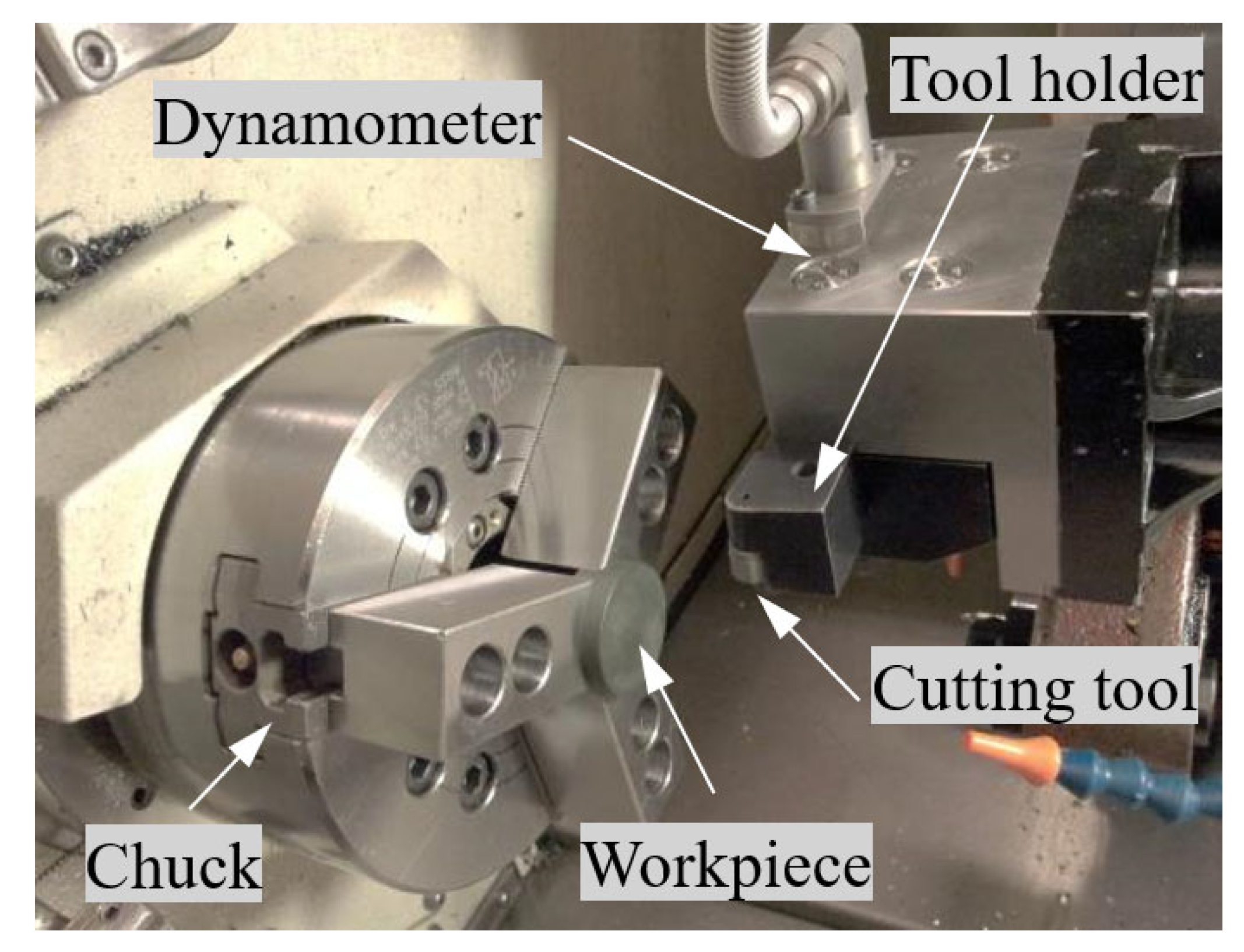
2. Materials and Experimental Procedures

The machining tests were conducted on Inconel 718 alloy, which has been commonly used in aircraft engines because of its excellent properties at elevated temperatures. The chemical composition of this alloy is given in Table 1. Before being cut, the work material was solution-heat-treated and artificially aged for precipitation hardening to a Rockwell hardness of 37 HRC.
A series of dry and wet machining tests were carried out on a NEXUS QTN100 CNC lathe with a maximum spindle speed of 6000 rpm and a power of 15 HP (Figure 1). Disk-shaped samples, with a diameter of 38 mm and a height of 15 mm, were machined using chamfered silicon carbide whisker-reinforced ceramic inserts. A fresh cutting edge was used after each cutting test in order to eliminate the impact of possible tool wear and to avoid important alterations in the cutting-edge geometry. The machining conditions are presented in Table 2. As far as cutting forces are concerned, a Kistler Quartz three-component dynamometer (model 9257B) was used. It has a measurement uncertainty of ±1 and ±2%, arising from linearity and crosstalk, respectively. LabVIEW 2024 software was used to record cutting forces (tangential ( P c ), feed ( P f ), and passive ( P p )) at a sampling frequency of 48 kHz. In order to eliminate the noise caused by the machining system, the cutting forces signals were filtered using a 4th-order low-pass Butterworth filter with a 3dB cutoff frequency of 800 Hz. After each cutting experiment, chips were collected to be analyzed with a binocular optical microscope.

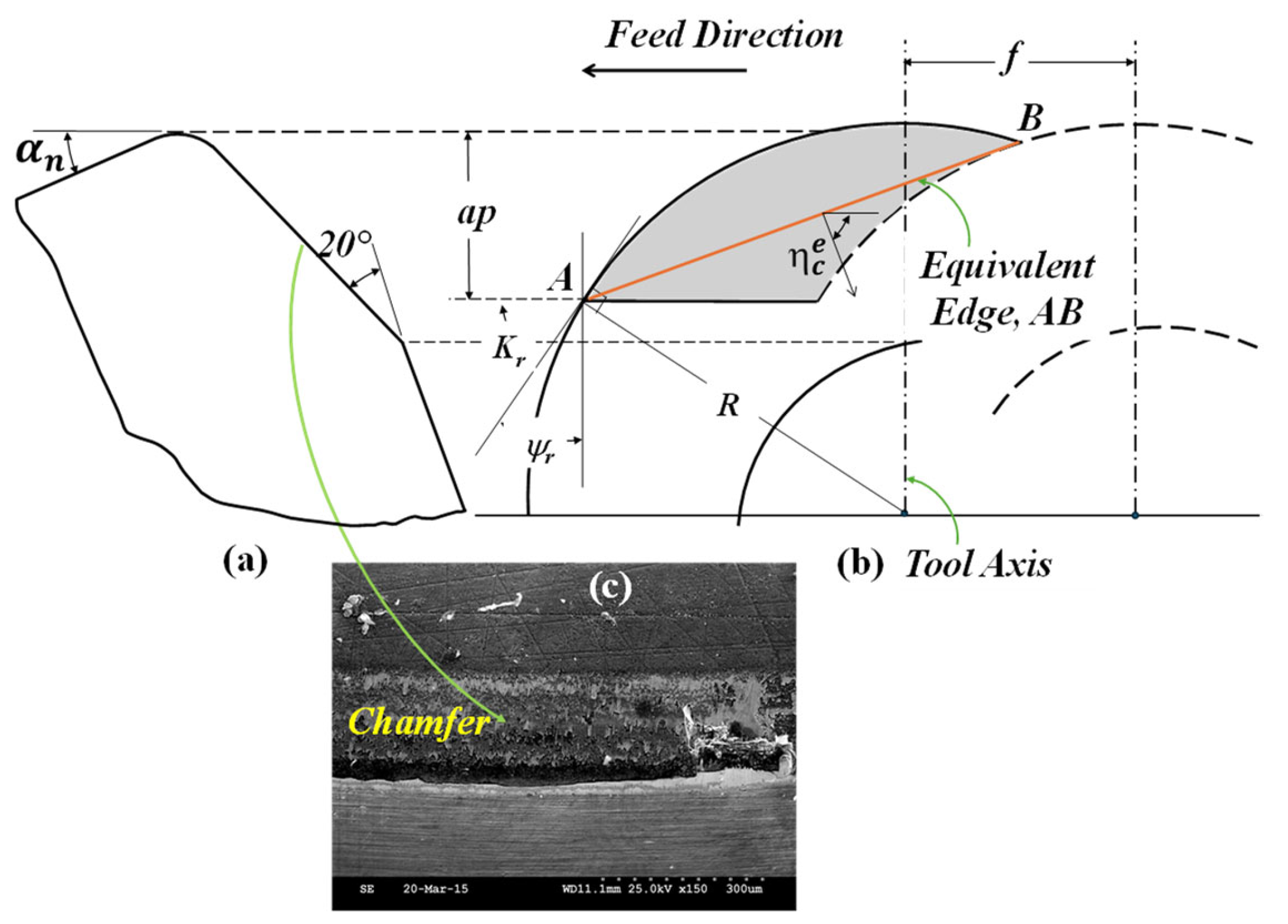
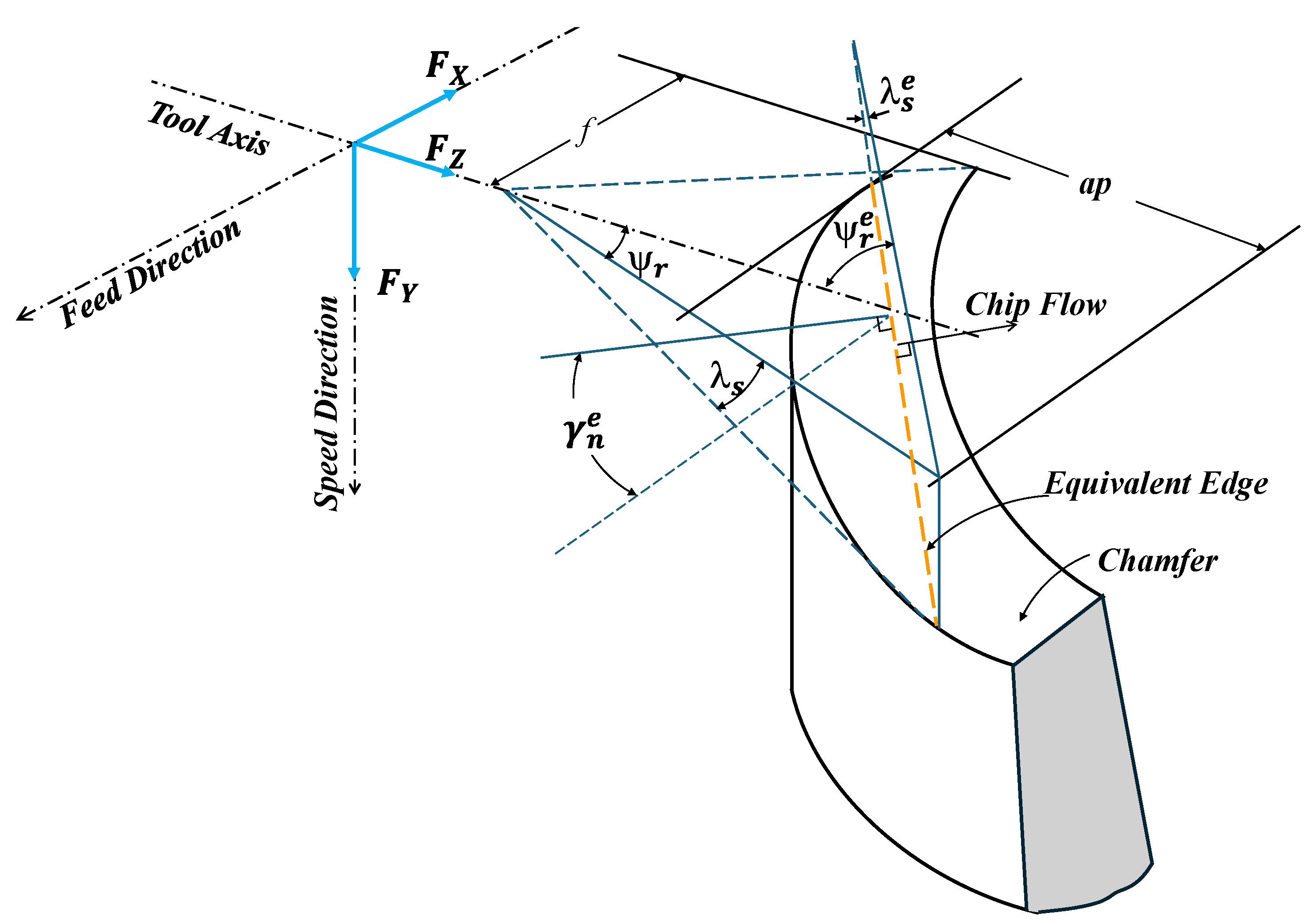
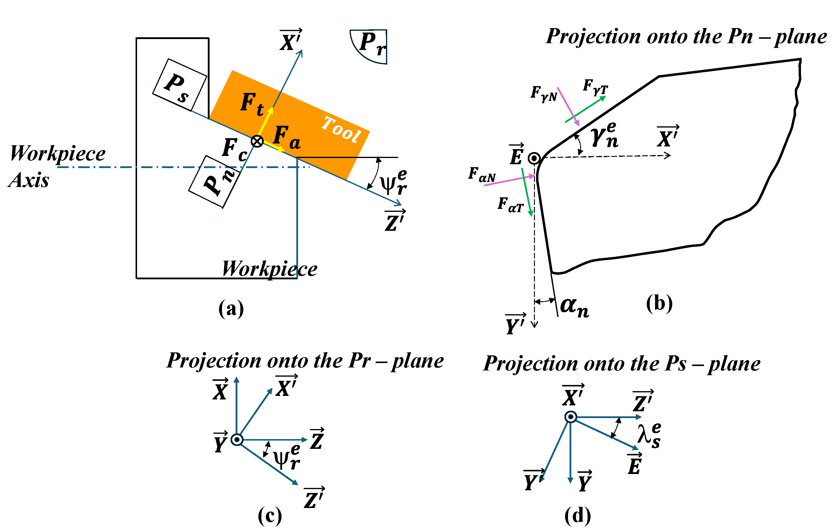
3. Friction Modeling for Turning with a Round Chamfered Insert

An analytical force model is proposed to assess friction forces and coefficients on the cutting tool rake and flank faces. This model is based on the 3D-to-oblique cutting transformation and the equivalent cutting edge (ECE) concept proposed by Colwell. [28]. The ECE is determined by establishing a connection between two extreme points of the undeformed chip section, as illustrated in Figure 2. The ECE is an oblique cutting edge and is defined by the equivalent side cutting edge angle Ψ r e , inclination angle λ s e , and normal rake angle γ n e (see Figure 2 and Figure 3) which are given as follows [29]:
Ψ r e = tan 1 f 2 + R 2 R a p 2 R 2 f 4 2 R a p
λ s e = tan 1 [ tan ( γ b ) cos ( Ψ r e ) tan ( γ s ) sin ( Ψ r e ) ]
γ n e = tan 1 [ tan ( γ b ) sin ( Ψ r e ) + [ tan ( γ s ) cos ( Ψ r e ) ] cos ( λ s e )
where γ b and γ s refer to the back and side rake angle. It is worth noting that the chip flow angle η c is defined between the chip flow direction and the feed direction, as illustrated in Figure 2. Various equations were established to predict η c , but most of them gave very low values under the machining conditions tested in the present work. The most reasonable value was obtained using the formula proposed by Outeiro et al. [30]:
η c = π 2 tan 1 1 R a p 1 1 f 2 R 2 R a p 1 + R 2 a p f R
where a p , f , and R refer to the depth of cut, feed rate, and tool radius, respectively.
The angles Ψ r e ,   λ s e ,  and γ n e are indispensable for the calculation of the transformation matrices from the oblique coordination systems ( X ,   E , Y ) and ( X , Y ,   Z ) to the 3D turning coordination system ( X ,   Y , Z ), as illustrated in Figure 4. To carry this out, the normal F γ N and tangential F γ T friction forces applied to the rake face (Figure 4b) were resolved into three cutting forces ( F c , F t , F a ), which were applied with respect to the oblique coordination system ( X , Y ,   Z ) (Figure 4a). The transformation matrix T M O is given by [31]:
F c F t F a = T M O F γ N F γ T = cos λ s e cos γ n e sin η c sin λ s e + cos η c cos λ s e sin γ n e sin γ n e cos η c cos γ n e sin λ s e cos γ n e sin η c cos λ s e cos η c sin λ s e sin γ n e F γ N F γ T
Then, the oblique cutting force F o c , thrust force F o t , and passive force F o a were resolved into the three cutting forces, generated by the 3D turning, named feed force P f , cutting force P c , and passive force P p , defined in the ( X , Y , Z ) system (see Figure 3) using the transformation matrix T M T as follows:
P c P f P p = T M T F c F t F a = 1 0 0 cos Ψ r e 0 sin Ψ r e 0 sin Ψ r e cos Ψ r e F c F t F a
The tangential F γ T and normal F γ N friction forces are, therefore, calculated by solving the following equation:
F γ N F γ T = T M T T M O 1 P c P f P p
Similarly, the normal F α N and tangential F α T friction forces applied to the flank face (see Figure 4b) were calculated in terms of P f , P c , and P p by rotating the system ( X , Y , Z ) by the angles Ψ r e , λ s e , and α n (see Figure 4c,d) as follows:
F α T = P c cos λ s e cos α n + P p sin Ψ r e + P f cos Ψ r e sin α n
F α N = P c cos λ s e sin α n + P p sin Ψ r e + P f cos Ψ r e cos α n
where P f , P c , and P p represent the feed force, tangential force, and passive force, respectively, which were measured during face-turning experiments.
The average friction coefficient on the rake ( μ γ ) and flank ( μ α ) faces are given by
μ γ = F γ T F γ N
μ α = F α T F α N

4. Results

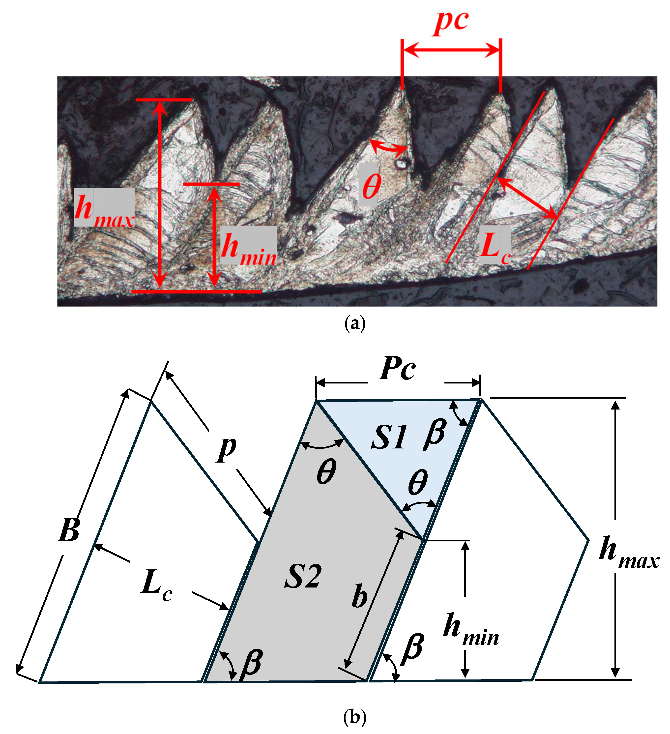
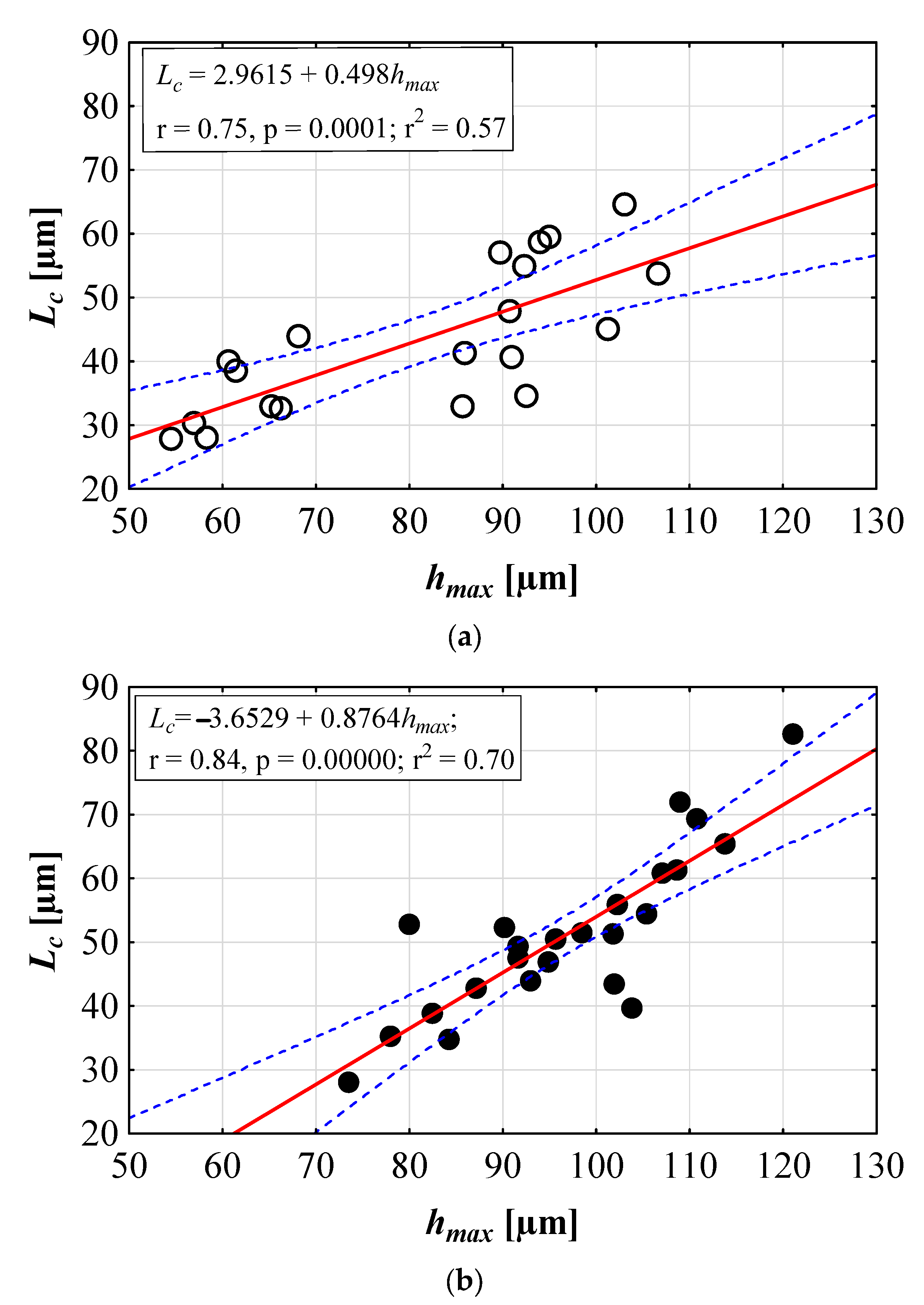
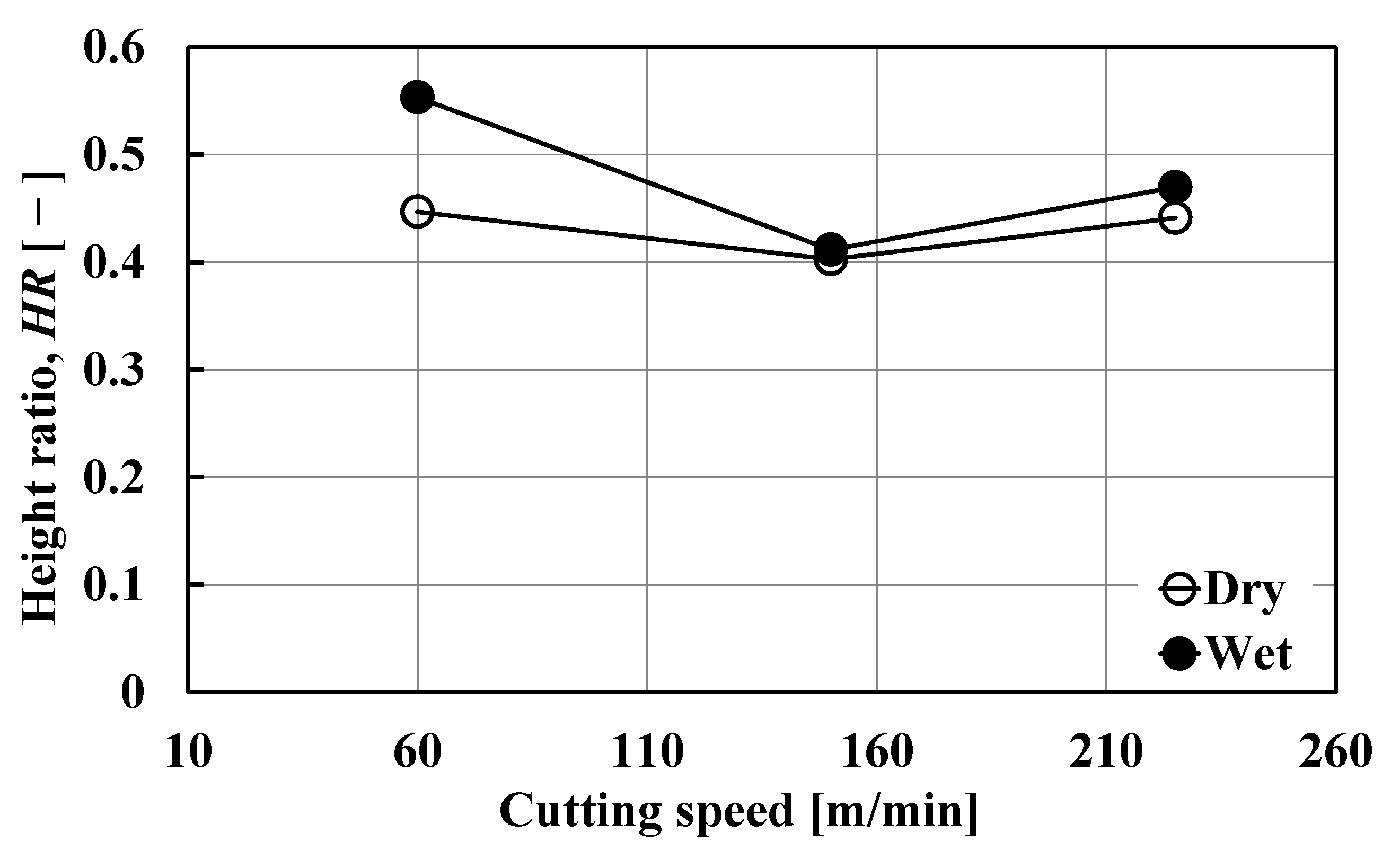
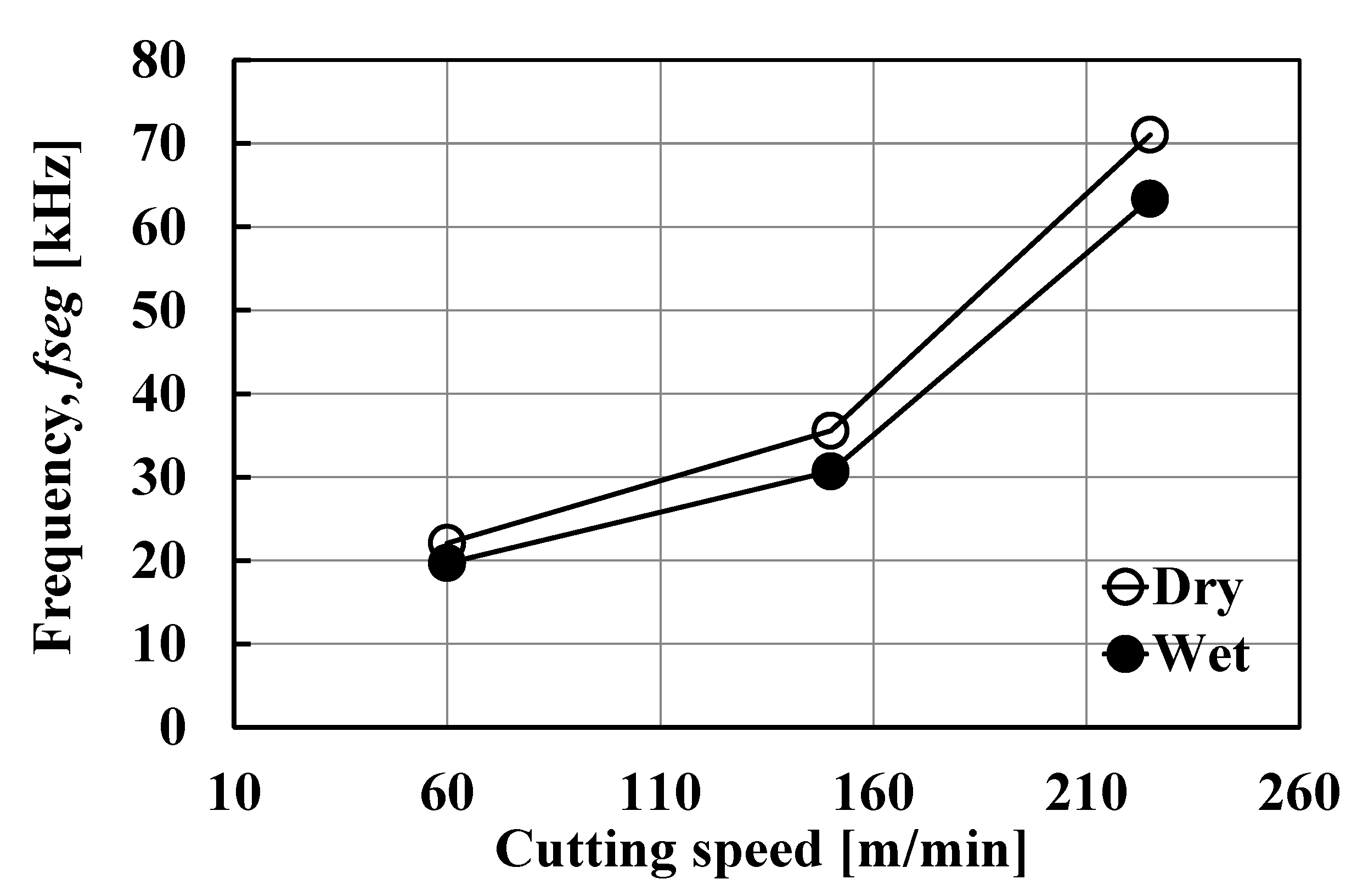
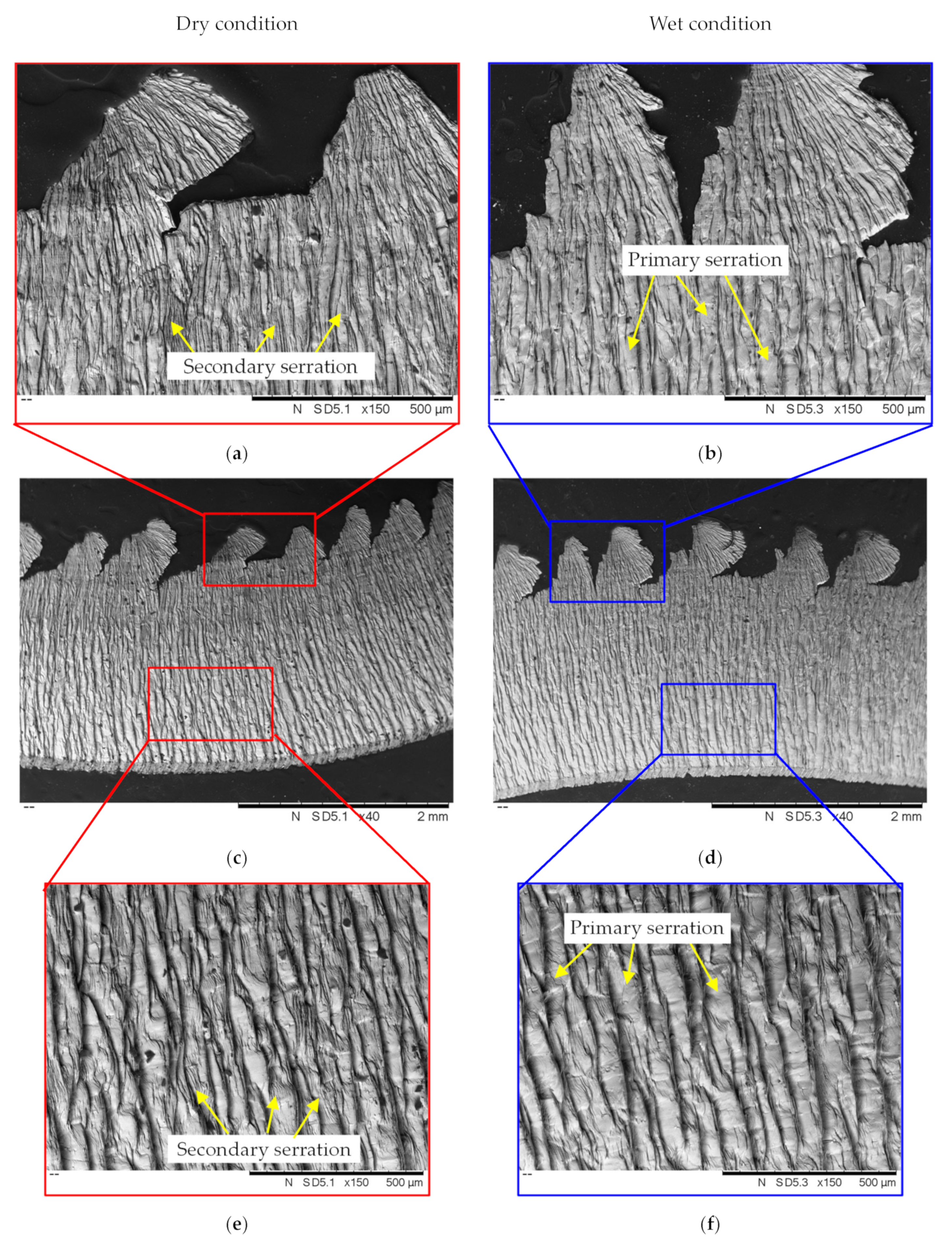
4.1. Chip Morphology
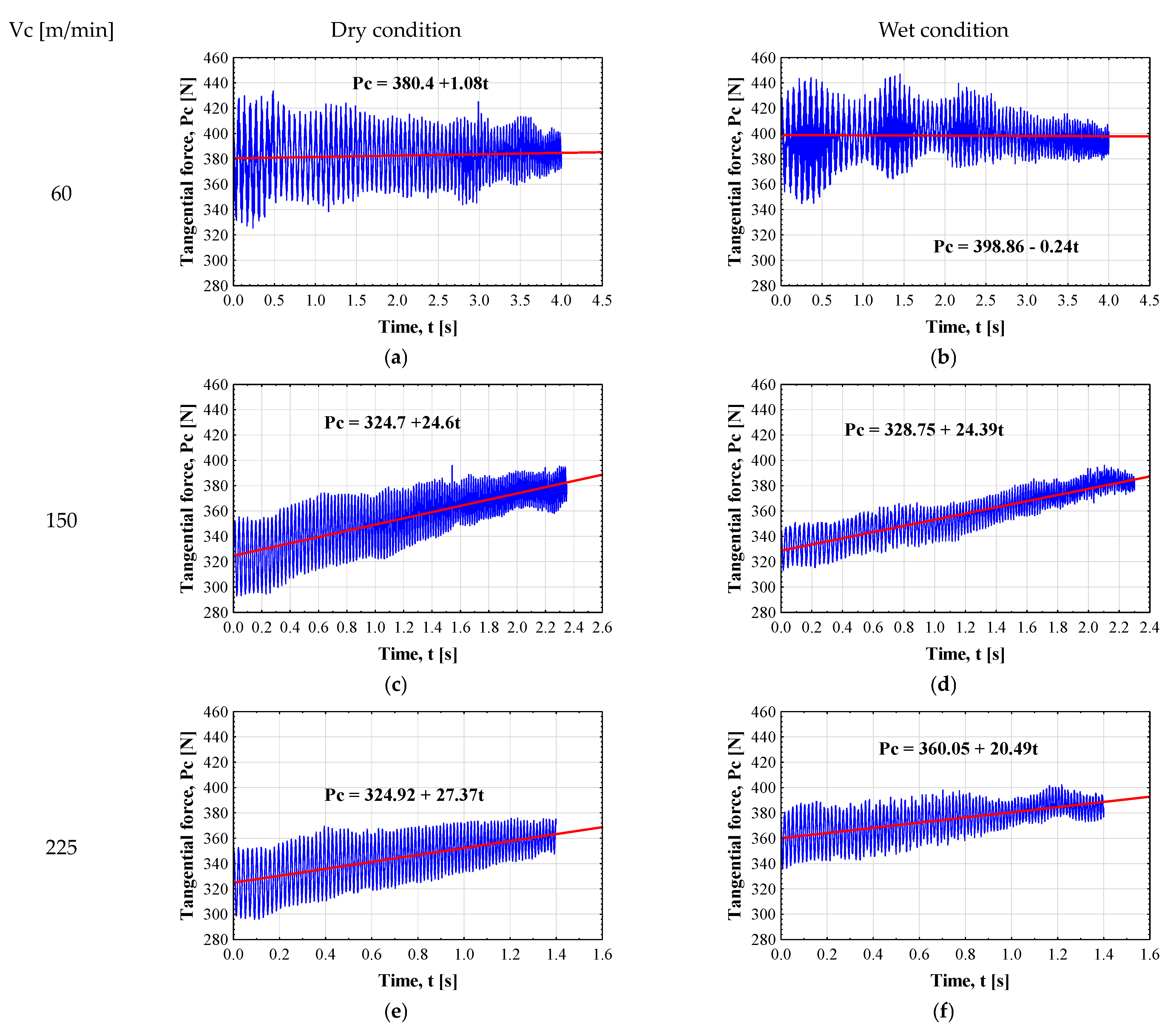
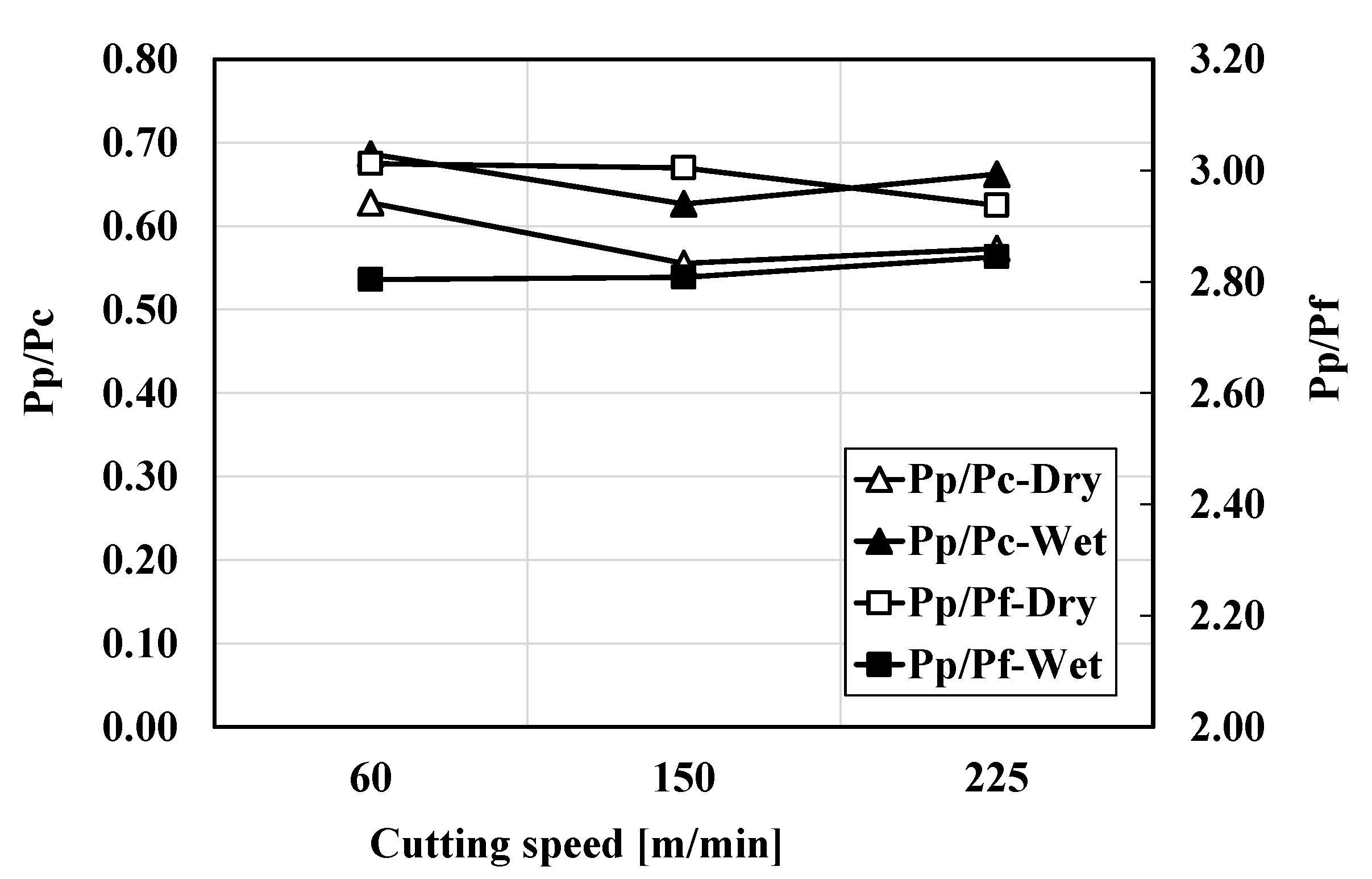
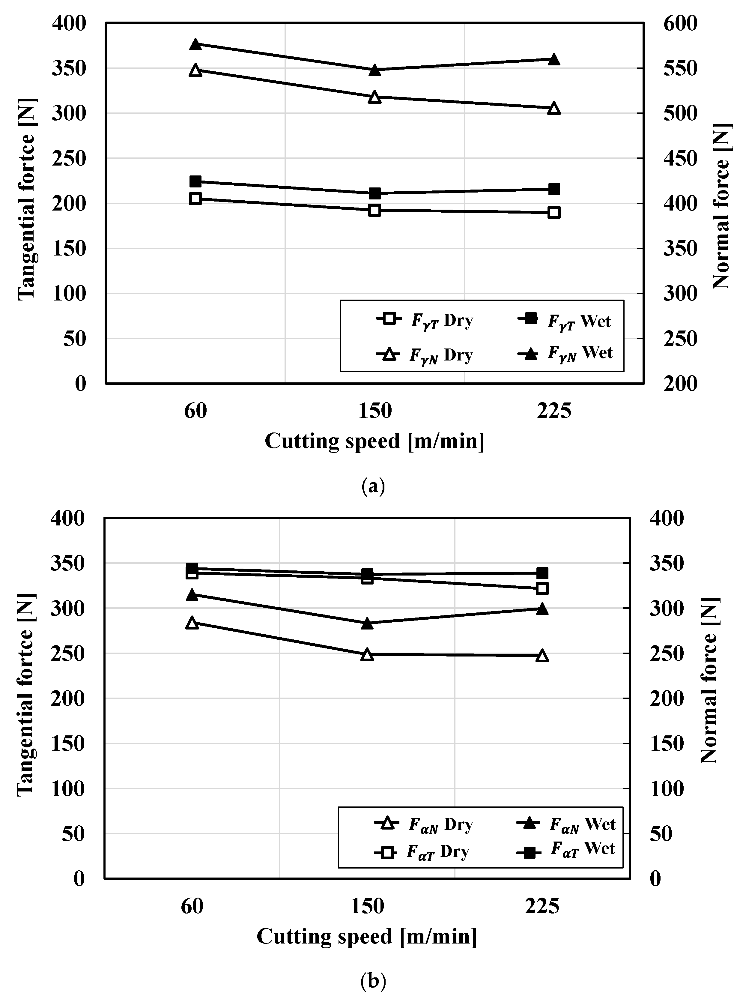
Analyzing chip morphology is imperative to understand the material deformation mechanism that takes place during machining under dry and wet conditions. Serrated chips, commonly called segmented or saw-toothed chips, were produced under both dry and wet conditions, even at low cutting speeds (60 m/min) (see Figure 5). Interestingly, the chip morphology under dry and wet conditions differed at low cutting speeds, but their similarity increased with the cutting speed. To discriminate the effect of the cutting fluid on serrated chip formation, a quantitative analysis of the geometrical parameters of chip segments was required. The serrated chip morphology can be characterized using the geometric parameters [32,33] of minimum height h m i n maximum height h m a x , distance between two consecutive teeth (pitch) p c , included angle θ, and shear band spacing L c , as depicted in Figure 6. To determine the possible correlations between these parameters, a multivariate analysis was performed. The results showed that the highest correlations were observed between L c , p c , h m a x , and h m i n under the dry condition, as shown in Table 3, while for the wet condition, the only significant correlation was found between L c and h m a x (see Table 4). To further analyze the relationship between L c and h m a x under the two machining conditions, the L c versus h m a x curves are plotted in Figure 7. A linear regression analysis between L c and h m a x under dry conditions (see Figure 7a) demonstrated high dispersion with a low R2 value (0.57). In contrast, the use of cutting fluid under wet conditions resulted in a significantly higher R2 value (0.70) alongside reduced dispersion. This finding indicates that chip-formation mechanisms became more stable and less sensitive to variations in cutting speed when coolant was employed. Further, this means that, regardless of the machining conditions used, thicker serrated chips experience larger shear band spacing under wet conditions.
Several relationships between serrated chip parameters have been established to assess the serration intensity over machining conditions. However, most of the proposed formulae failed to represent the whole aspect of chip serration intensity. For instance, the examination of several chip serration micrographs from previous works has revealed that different chip morphologies can lead to a similar chip height ratio HR, ( h m i n / h m a x ). For this purpose, two new indexes of serration intensity, named the Area Function (AF) and the Shape Function (SF), were proposed.
Referring to Figure 6b, a perfectly continuous chip is formed from segments with a rhomboid shape with a total area equal to the sum of the element areas S1 and S2. Chip serration occurred when area S1 began to increase while S2 (chip material) decreased. The intensity of the chip serration can therefore be expressed based on the geometric parameters in Figure 6b by the following equation:
A F = S 1 S 2 = L c tan θ + p c 2 L c 2 h m a x + h m i n sin β
Given that the number of segments per unit length is a relevant parameter of serration intensity, a Shape Function (SF) is introduced to discriminate serrated chips with thin segments from those with thick segments by considering the shear band spacing L c . As demonstrated above, the consideration of L c in conjunction with h m a x can offer enhanced sensitivity of SF to cutting conditions. The SF index is given by
S F = B b × L c = h m a x h m i n × L c
Figure 8a displays the effect of cutting speed and coolant on AF. Under dry conditions, AF was almost constant at cutting speeds ranging between 60 and 150 m/min and decreased at 225 m/min. Conversely, under wet conditions, AF significantly increased with the cutting speed from 60 to 150 m/min and slightly decreased at 225 m/min. This showed an interaction effect between cutting speed and cutting fluid usage. As demonstrated in Figure 8a, the AF index indicated that at a cutting speed of 150 m/min, both dry and wet conditions yielded comparable levels of serration intensity. However, a substantial increase in serration intensity was observed at low speed and dry conditions in comparison to the wet conditions. The opposite trend was observed at a cutting speed of 225 m/min. The SF curves (Figure 8b) showed that dry conditions produced a higher serration intensity than wet conditions over the range of speeds tested. In a similar way to the AF, the difference between the SF in dry and wet conditions was more pronounced at a lower speed (60 m/min). In the same way as the AF curves showed, the SF curves also showed that there was a change in the trends at a cutting speed of 150 m/min in both dry and wet conditions. From the chip micrographs (Figure 5), it is clear that chip segments produced under dry conditions were thinner than those produced in wet conditions, which further contributed to the intensity of the serration. The SF was able to capture this phenomenon properly, although the AF takes more chip geometric parameters into account.
The chip height ratio HR ( h m i n / h m a x ), which is the most used serration index in the literature, was calculated using the experimental data of the present study and is displayed in Figure 9. The rule of thumb is that the more intense the chip serration, the lower the HR. Therefore, HR shows high chip serration intensity in dry conditions compared to wet conditions, particularly at a low cutting speed of 60 m/min (Figure 9). This agrees with the AF and SF indexes. However, HR failed to capture the actual chip serration intensity at high cutting speeds, where HR values of dry and wet conditions are very similar (Figure 9). This demonstrated the reliability of the proposed new serration intensity indexes AF and SF in discriminating the morphology of apparently similar chip segments.
Segmentation frequency f s e g is another relevant parameter characterizing the serration intensity. Various formulae of f s e g can be found in the literature. In the present study, the following equation was used [34]:
f s e g = r c V p c
where r c denotes the chip compression ratio given by:
r c = p p c
p c denotes the mean distance between cracks on the work material and V denotes the cutting speed.
Figure 10 illustrates the effects of cutting speed on segmentation frequency under dry and wet conditions. Increasing the cutting speed led to an increase in the chip segmentation frequency in both conditions. Mostly, in the dry condition, chips were more likely to break up more often than when using cutting fluid. It should be emphasized that the rate at which the segmentation frequency changes increased when machining faster than 150 m/min. This corroborated the hypothesis that a significant change in chip-formation mechanisms occurred at a cutting speed of 150 mm/min independently of the machining conditions used. This finding was consistent with the analysis of the AF and SF serration intensity index curves (Figure 8). Furthermore, the chip frequency trends were consistent with the SF index (Figure 8a), suggesting that it is a proper index of chip serration intensity, capturing well the effect of the cutting fluid.

4.2. Cutting Forces

Machining forces are important indicators of the difficulty or ease of the cutting process, and how this is affected by the setting parameters and machining conditions. It can provide a better explanation of the material’s behavior and the chip-forming mechanism as a function of cutting speed and machining conditions. Figure 11 displays the tangential force ( P c ) signal recorded during the effective machining time for different cutting speeds and machining conditions. The magnitude of the tangential force remained constant over the machining time at low cutting speeds under dry and wet conditions, as depicted in Figure 11a,b, respectively. However, as the cutting speed was increased, the tangential force began to rise in a time-dependent manner, as demonstrated by the slope of the linear regression line (red line) (see Figure 11c–f). The rate of increase in the average value of the tangential force peaks is 27.37 N/s at a cutting speed of 225 m/min in dry conditions (see Figure 11e). When cutting fluid was applied, the maximum rate of increase (24.39 N/s) was achieved at 150 m/min and decreased to 20.49 N/s at 225 m/min. However, the dynamic component (signal fluctuation) of the tangential force was higher in the dry condition than in the wet condition. This dynamic component has a high value at the beginning of the cutting process and then decreases over time, in a similar way under both dry and wet conditions. The lowest value of the dynamic component was recorded at a speed of 150 m/min in wet conditions.
Since the forces signals (see Figure 11) were not stable and the mean values increased with machining time, the average cutting forces were considered. The average value of the P c , P f , and P p were calculated at the end of the machining time of each test. The force ratios P p / P c and P p / P f were then calculated from the force signals and plotted in Figure 12. The results demonstrated that the cutting speed did not exert a significant influence on the force ratios. However, the presence of cutting fluid appeared to have a minor effect. The average P p / P c ratio exhibited an increase from 0.58 in a dry condition to 0.66 in a wet condition, while the P p / P f ratio decreased from 2.98 to 2.81. Additionally, the P p / P c and P p / P f ratios indicated that the tangential force was higher than the passive force, while the reverse was observed for the feed force, independently of the cutting speed and machining conditions used.

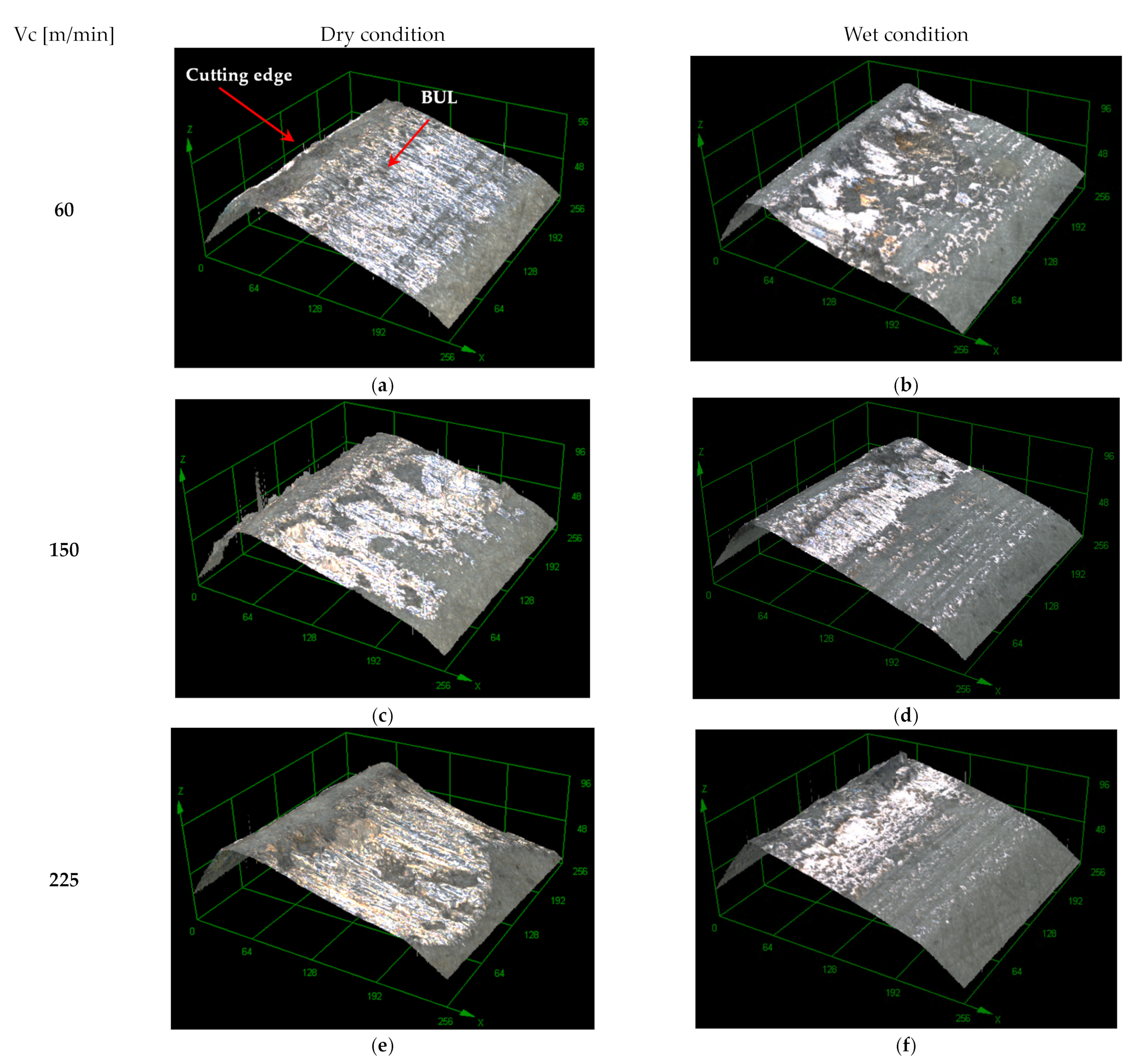
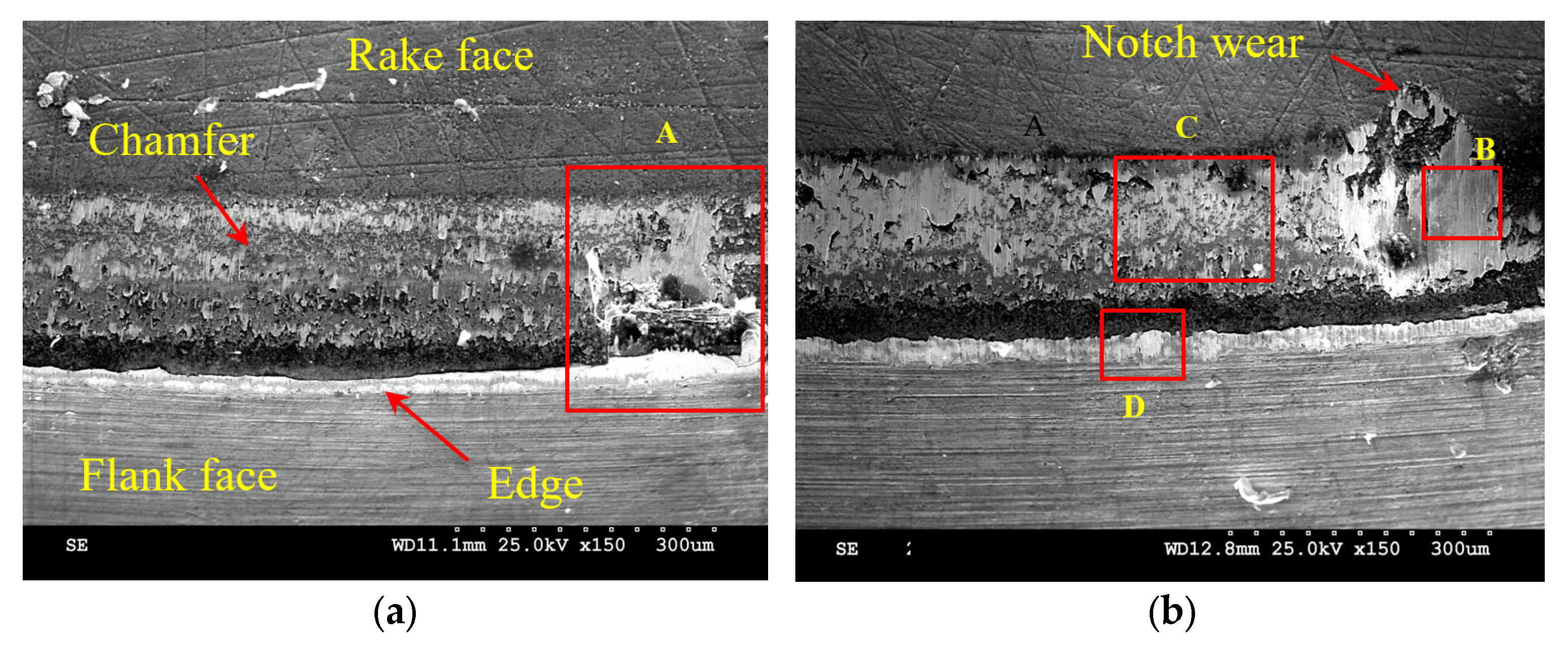
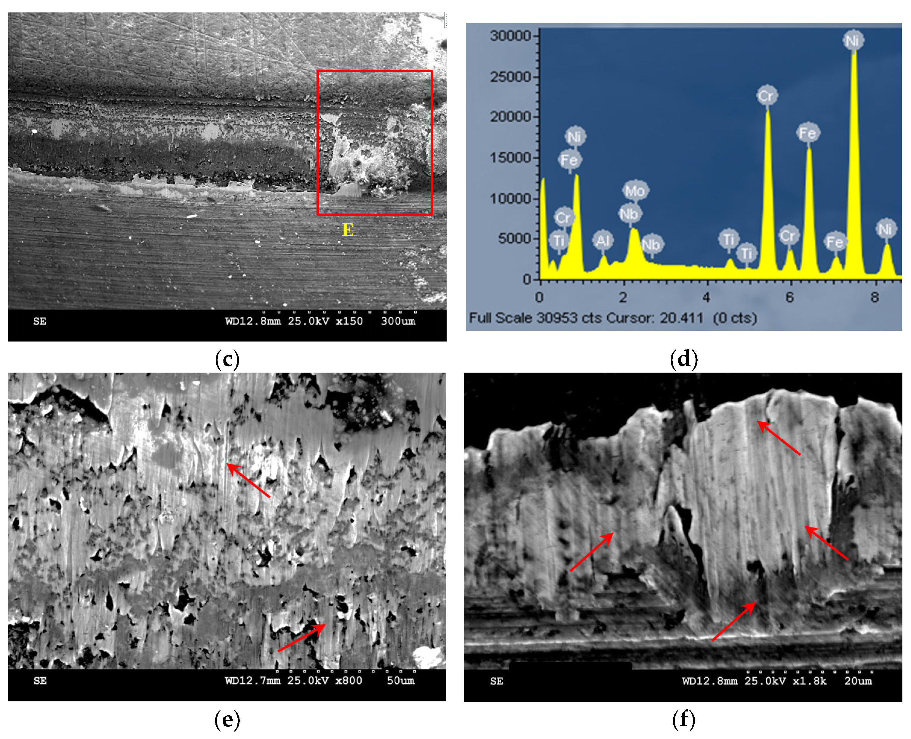
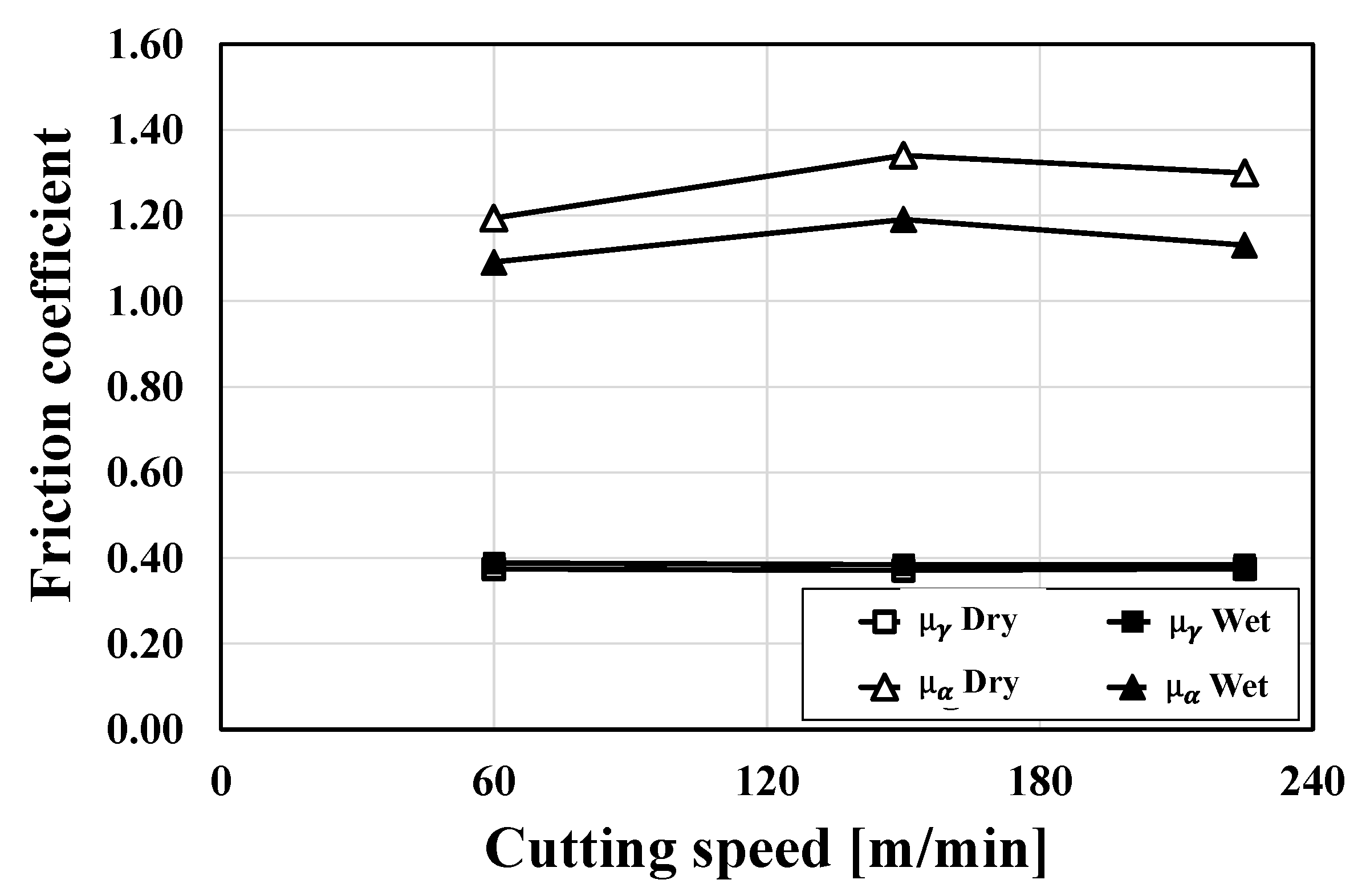
4.3. Tool Wear and Friction

In machining practice, the use of cutting fluid was substantiated by its beneficial lubrication and cooling effects on the cutting tool wear and friction at the contacts between the cutting tool and the chip/work material. To understand the effect of the cutting fluid and how it interacts with the cutting speed, cutting inserts were analyzed at the end of the machining test. Figure 13 depicts laser optical images of the chamfer land of the cutting insert after dry and wet machining. The images show that the cutting process predominantly occurred within the chamfer zone under both dry and wet conditions, irrespective of the cutting speed. Furthermore, the presence of a built-up layer (BUL) (bright zone) was observed in dry conditions, covering most of the chamfer land. In contrast, this zone was found to be restricted to a reduced area in wet conditions. Curiously, narrower BUL-affected zones were acheived at a cutting speed of 150 m/min for both dry and wet conditions, as shown in Figure 13c,d, respectively. To gain further insight into the cutting-edge condition, a SEM analysis was conducted, and the resulting micrographs are presented in Figure 14. The micrographs revealed a form of wear at low cutting speed in dry conditions (see Figure 14a), but an excessive build-up layer was present at the depth of cutting level (see Figure 14a, Detail A). A further increase in cutting speed to 225 m/min resulted in excessive BUL formation on the chamfer land and the appearance of notch wear, as can be seen in Figure 14b. An Electron-Dispersive Spectroscopy (EDS) analysis of the BUL on the notch zone (Figure 14d, Detail B) revealed the presence of Nb and Ti, which were derived from the NbC and TiC present in the workpiece material (Inconel 718). As shown in Figure 14e,f, these carbides caused a severe abrasion effect, resulting in micro-grooves on the chamfer land and flank surface. It is important to note that in wet conditions and at high cutting speeds (225 m/min), although there is a build-up of material at the depth of the cut level (Figure 14c, Detail E), no notch wear was observed.
The friction model outlined in Section 3 was employed to evaluate the friction forces and coefficients of friction on the rake face (chamfer land) and the flank face. The tangential and normal friction forces acting on the rake and flank faces are depicted in Figure 15a and Figure 15b, respectively. As demonstrated in Figure 15a, the cutting speed did not exert a significant effect on the friction forces acting on the rake face. However, the application of cutting fluid led to a slight increase in both normal and tangential friction forces. Furthermore, the normal friction forces were considerably higher (×2) than the tangential force. Conversely, the normal friction force was lower than the tangential friction force on the flank face, and the application of coolant increased it slightly (see Figure 15b). Similarly to the rake face, the cutting speed had no significant effect on the friction forces acting on the flank face. The friction coefficient was calculated using the normal and tangential friction forces and is presented in Figure 16. Again, the cutting speed seemed to have no significant effect on the friction coefficient. Furthermore, the cutting fluid appeared to exert minimal influence on the friction coefficient of the flank face.

5. Discussion

Regarding the process of chip formation, it has been observed that serrated chips were produced at all cutting speeds under both dry and wet conditions, which agreed with most of the previous works dealing with the machining of nickel-based superalloys. It can thus be concluded that the chip-formation process is primarily driven by periodic catastrophic thermo-plastic shear instability, resulting from a competition between the thermal softening and the strain hardening of the work material being cut [35,36]. However, an analysis of chip micrographs and serration intensity indexes has demonstrated that chip morphology is contingent on cutting speed and machining conditions (dry or wet). Specifically, when machining at low cutting speed (60 m/min) with cutting fluid, the chips were thicker (high h m a x ) with a high h m i n , resulting in lower chip serration intensity indexes compared to those generated under dry conditions. This phenomenon can be attributed to the enhanced strain-hardening effect observed in wet conditions, where the exposure time is sufficient to adequately cool the work material, as previously reported in [37].
In the context of dry machining, it was observed that the generation of excessive heat promotes thermal softening, even at low cutting speeds. It has been demonstrated that a low cutting speed facilitated heat exchange between the tool and the chip. This phenomenon appeared to be mitigated by the application of cutting fluid. To elucidate this, the free surface of the chips was analyzed (see Figure 17). In both dry and wet conditions, the lamella structure was evident, aligned with the direction of chip flow, as illustrated in Figure 17c,d, respectively. The formation of this lamella structure unequivocally signified the occurrence of shear localization, as reported in [38]. In dry conditions, an increase in temperature resulted in a significant reduction in chip strength, leading to multiple shear plane activation and, therefore, an increase in the number of secondary serrations. This phenomenon is illustrated in Figure 17a,e. Conversely, under wet cutting conditions, characterized by lower cutting speeds, plastic deformation became more localized due to a greater competition between strain hardening and thermal softening, as demonstrated in Figure 17b,f.
As the cutting speed was increased, thermal softening became the predominant factor, resulting in a decrease in the shear strength of the work material within a narrow band compared to its original strength. Consequently, cracks initiated and propagated towards the tool tip, leading to the formation of more shear-localized chips [39,40]. At a cutting speed of 150 m/min, cutting fluid appeared to have a reduced effect due to the high aerodynamic air flow surrounding the workpiece. Consequently, the chip serration intensity in both environments was found to be similar at this cutting speed. A further increase in cutting speed to 225 m/min led to high chip serration due to segment thinning, as shown by the Shape Function (SF) (see Figure 8b). This phenomenon was attributed to the intensifying of the thermal softening against the strain hardening, driven by the same aerodynamic airflow effect observed at the cutting speed of 150 m/min [34,41].
It is interesting to note that the increase in thermal softening and the activation of multiple shear planes resulted in unstable chip segment dimensions and forms, such as segment twining and high dispersion of h m a x , particularly with dry machining (see Figure 5e). This instability appears to be mitigated by the use of a cutting fluid, as evidenced by the uniformity in chip segment shapes and the high linear correlation between shear band spacing and maximum segment heights observed in wet conditions, as illustrated in Figure 5f and Figure 7b, respectively. The most regular and stable shape and dimension of chip segments were observed at a cutting speed of 150 m/min. This is also the cutting speed at which significant changes in the slope of the chip segmentation frequency curves were experienced, in both dry and wet conditions.
The chip-formation process seemed to have some effect on cutting forces, as demonstrated by the dynamic components of the forces signal, which were found to be higher in dry conditions (see Figure 11). This is an expected outcome given the documented propensity of serrated chips to generate significant fluctuations in cutting forces signals. However, at a low cutting speed of 60 m/min, the cutting force signal of the wet conditions displayed significant and random fluctuations in force over the duration of the machining process. This was attributed to the high-strain hardening effects imposed by the cutting fluid. This finding is consistent with the observations reported by Sun et al. [42] during the machining of a titanium alloy, which indicated that the transition toward continuous chips may be the underlying cause of this trend. This is in accordance with the results presented in this study, which demonstrated a low serration intensity of chips generated at a low cutting speed under wet conditions, as illustrated in Figure 5b. In general, the results of the present work show that the wet conditions seem to slightly increase the average force values because of the cooling effect, particularly at low cutting speeds [43].
Figure 12 illustrates that the passive force ( P P ) was lower than the tangential force ( P C ) and significantly higher than the feed force ( P f ). These results are in agreement with those obtained in [44,45]. This can be attributed to the interaction of several technological parameters, particularly the combination of round inserts (∅ 12.7 mm) and a finishing condition (depth of cut = 0.5 mm, feed rate = 0.1 mm/rev) that resulted in a low cutting-edge angle (23°) and a large chamfer angle (20°) of the cutting insert. Interestingly, the average passive-to-cutting force ratio ( P P / P C ) increased slightly from 0.58 in dry conditions to 0.66 in wet conditions (see Figure 12). In contrast, the mean passive-to-feed force ratio ( P P / P f ) showed a slight decrease from 2.98 in wet conditions to 2.82 in dry conditions. Notably, among the force components, the passive forces experienced the most substantial increase when using wet conditions. It can thus be concluded that, despite the tangential force ( P C ) exceeding the passive force ( P P ), the rate at which it increased, due to the high strain hardening of the work material in wet conditions, was insufficient to counterbalance the rise in P P . Conversely, the feed force P f experienced an inverse relationship, as the ploughing action induced by the chamfer exhibited an increase when the cutting fluid was applied due to the strain-hardening effects of the work material and the reduced feed rate (0.1 m/min) [46].
The interaction between the cutting tool and work material, in conjunction with the subsequent chip formation process, significantly influenced the contact characteristics of the cutting tool’s rake and flank faces. Despite the high tangential and normal friction forces at both the rake and flank faces under wet conditions, Figure 15 and Figure 16 clearly show that the resulting friction coefficient was higher on the flank face compared to the dry conditions. The friction coefficient on the flank face exceeded 1, while it was at approximately 0.4 on the rake face in both machining conditions. This is a common observation in metal-cutting tribology and has been confirmed experimentally by Grzesik et al., who have reported that the shear stress is higher than the normal stress on the flank region near the cutting edge [47]. This phenomenon can be attributed to the higher passive force and the contact between the cutting edge and the newly machined surface. This contact is mainly elastic, as opposed to being seizure-prone; see Figure 13. Moreover, Komanduri and Turkovich [48] asserted that the material flow during the upsetting stage of chip segmentation is analogous to a drawing operation, involving the application of high normal stress to the cutting edge. Conversely, the BUL observed on the rake face (see Figure 13) induced a high tangential friction force due to seizure effects, resulting in a coefficient of friction higher than unity.
As demonstrated in Figure 13, the extent of the BUL (bright zone) is indicative of the contact area between the chip and the rake face of the tool. It is evident that the chip/tool contact area is significantly reduced in wet conditions in comparison to dry conditions. Furthermore, this area exhibited a slight increase with cutting speed during dry machining, while the opposite was observed in wet machining. To elucidate this phenomenon, it was imperative to consider three predominant phenomena: the coolant effect, the lubricant effect, and the mechanical effect associated with the utilization of cutting fluid during machining. In general, during wet machining, the cutting fluid exerts force on the chips, thereby reducing their curling and consequently diminishing their contact with the cutting tool. At low cutting speeds (60 mm/min), the chips were exposed to the cutting fluid for a longer time, which made them more susceptible to embrittlement due to the cooling effect. Additionally, at low cutting speeds, the reduced aerodynamic effect facilitates the penetration of the metalworking fluid into the chip/tool interface, thereby enhancing its lubricant effect [49]. Conversely, at elevated cutting speeds, the chip velocity and aerodynamic effect are sufficiently high to substantially diminish the cooling and lubricant effects. Nevertheless, the cutting fluid continued to exert a force on the chip, thereby reducing the chip’s curling radius and chip/tool contact area [50].
The analysis of the back surface of the chip obtained in dry conditions (see Figure 18a) demonstrated severe material flow and damage (see Figure 18c), thereby providing evidence of a substantial seizure effect. Conversely, these defects were significantly mitigated by employing a wet condition (see Figure 18d). However, the model of the apparent coefficient of friction employed in the present study was incapable of discriminating the effect of cutting fluid on the rake face (see Figure 16), suggesting a complex contact between the rake face and the chip, involving sticking and sliding zones.
Despite the reduced machining time, the presence of notching wear in the depth of the cutting zone at a cutting speed of 225 m/min and in a dry condition (see Figure 14b) is indicative of extreme friction and contact conditions. Notching wear is a prevalent phenomenon during the machining of nickel-based alloys and is primarily attributed to strain hardening, element diffusion between chips and the tool material, and the presence of abrasive carbides in the work material [51]. It is interesting to note that notching wear was avoided by the application of cutting fluid (see Figure 14c). However, it should be noted that wet conditions contribute to increased strain hardening effects, as previously explained. The cutting fluid was able to avoid a chemical reaction between the chip and the cutting tool by reducing the build-up of material at the intersection between the workpiece surface and the cutting edge (see Figure 14c). Further analysis and confirmation of this finding using wear tests is required in future work.

6. Conclusions

The high-speed machining of superalloy Inconel 718 under dry and wet conditions was investigated in this paper. The main goal was to elucidate the effectiveness of using cutting fluid at a high cutting speed in conjunction with ceramic inserts. To this end, an analytical friction model was proposed to evaluate the friction forces and coefficients on the rake and flank faces of the cutting tool. Furthermore, a comprehensive analysis of the chip-formation process was also conducted using two new chip serration intensity indexes.
The results have shown that wet conditions provided some interesting benefits against dry conditions. Wet machining was found to generate a stable serrated chip formation process, resulting in less fluctuation in cutting forces and, therefore, reducing the dynamic components of force signals. Furthermore, wet machining led to a reduced chip/tool contact area in comparison to dry machining. The results of the study demonstrated that as the cutting speed was increased, the coolant and lubricant effects decreased. However, the chip/tool contact area remained smaller than in dry conditions. This was attributed to the mechanical effect of cutting fluid on the chip. The friction analysis demonstrated that when applying cutting fluid, the coefficient of friction is reduced compared to dry conditions. Moreover, the results confirmed that the contact on the flank face of the cutting tool has a mainly elastic character and that the chip serration process contributed to an increase in the passive force. Nevertheless, high seizure effects were observed in dry conditions, as confirmed by the excessive built-up layer observed on the rake face of the cutting tool. The cutting fluid significantly reduced the built-up layer formation at all tested cutting speeds and helped prevent notching wear. It is important to note that a cutting speed of 150 m/min was found to generate a particular thermomechanical condition, leading to the most regular and stable shape and dimensions of chip segments. This speed also represents a threshold at which significant changes in the slope of the chip segmentation frequency curves were experienced, in both dry and wet conditions. In conclusion, the results have shown that wet conditions were capable of enhancing some machinability characteristics of the ceramic tool over dry conditions. However, further investigation is needed to have a better understanding of the friction behavior at the tool–workpiece contact during longer machining time and their corresponding influence on the machined surface integrity.

Author Contributions

W.J.: conceptualization; methodology; formal analysis; investigation; writing—original draft preparation; writing—review and editing; validation; visualization. M.D.: methodology; formal analysis; investigation; writing—review and editing. H.J.: investigation; writing—review and editing. P.B.: funding acquisition; writing—review and editing. All authors have read and agreed to the published version of the manuscript.

Funding

This research was funded by the Natural Sciences and Engineering Research Council of Canada (NSERC) - RGPIN-2023-05607.

Data Availability Statement

The original contributions presented in this study are included in the article. Further inquiries can be directed to the corresponding author.

Conflicts of Interest

The authors declare no conflicts of interest.

Abbreviations

The following abbreviations are used in this manuscript:
AFArea Function
BUEBuild-up-edge
BULBuild-up layer
DOCDepth of cut
ECEEquivalent cutting-edge
EDSElectron-Dispersive Spectroscopy
EDXEnergy dispersive X-ray spectroscopy
MQLMinimum quantity lubrication
SEMScanning electron microscopy
SFShape Function
TMTransformation matrix
WCCemented carbide

References

  1. Imbrogno, S.; Rinaldi, S.; Umbrello, D.; Filice, L.; Franchi, R.; Del Prete, A. A physically based constitutive model for predicting the surface integrity in machining of Waspaloy. Mater. Des. 2018, 152, 140–155. [Google Scholar]
  2. Su, R.; Hao, D.; He, P.; Wu, D.; Wang, Q.; Dong, H.; Ma, H. Effect of Co on creep and stress rupture properties of nickel-based superalloys—A review. J. Alloy. Compd. 2023, 967, 171744. [Google Scholar] [CrossRef]
  3. Tu, L.; Lin, L.; Liu, C.; Zheng, T.; Deng, Y.; Han, L.; An, Q.; Ming, W.; Chen, M. Tool wear characteristics analysis of cBN cutting tools in high-speed turning of Inconel 718. Ceram. Int. 2023, 49, 635–658. [Google Scholar] [CrossRef]
  4. De Bartolomeis, A.; Newman, S.T.; Jawahir, I.S.; Biermann, D.; Shokrani, A. Future research directions in the machining of Inconel 718. J. Mater. Process. Technol. 2021, 297, 117260. [Google Scholar] [CrossRef]
  5. Gao, C.; Wei, P.; Jin, S.; Zhang, J. Parametric investigation of laser incidence geometry in laser-assisted milling of Inconel 718. J. Mater. Res. Technol. 2024, 33, 2442–2454. [Google Scholar] [CrossRef]
  6. Moon, S.-H.; Lee, C.-M. A study on the machining characteristics using plasma assisted machining of AISI 1045 steel and Inconel 718. Int. J. Mech. Sci. 2018, 142, 595–602. [Google Scholar]
  7. Wang, Z.Y.; Rajurkar, K.P.; Fan, J.; Lei, S.; Shin, Y.C.; Petrescu, G. Hybrid machining of Inconel 718. Int. J. Mach. Tools Manuf. 2003, 43, 1391–1396. [Google Scholar]
  8. Qiu, W.; Pan, D.; Li, J.; Guo, P.; Qiao, Y.; Wang, X. Chip formation mechanism in cryogenic machining of high temperature alloy-Inconel 718 and Ti-47.5Al-2.5V-1.0Cr. J. Manuf. Process. 2023, 97, 35–47. [Google Scholar] [CrossRef]
  9. Damir, A.; Shi, B.; Elsayed, A.; Thelin, J.; M’saoubi, R.; Attia, H. On the tribological and thermal aspects of cryogenic machining of inconel 718 and Their Effects on Surface Integrity. Wear 2025, 205855. [Google Scholar] [CrossRef]
  10. Liu, H.; Meurer, M.; Bergs, T. Experimental and Finite Element Analysis of adapted cutting fluid supply on tool temperature and wear progression in Inconel 718 turning. J. Manuf. Process. 2025, 137, 166–180. [Google Scholar] [CrossRef]
  11. Amrita, M.; Kamesh, B. Optimization of graphene based minimum quantity lubrication of Inconel718 turning with multiple machining performances. Mater. Today Proc. 2021, 39, 1337–1344. [Google Scholar]
  12. Dudzinski, D.; Devillez, A.; Moufki, A.; Larrouquère, D.; Zerrouki, V.; Vigneau, J. A review of developments towards dry and high speed machining of Inconel 718 alloy. Int. J. Mach. Tools Manuf. 2004, 44, 439–456. [Google Scholar]
  13. Kui, G.W.A.; Islam, S.; Reddy, M.M.; Khandoker, N.; Chen, V.L.C. Recent progress and evolution of coolant usages in conventional machining methods: A comprehensive review. Int. J. Adv. Manuf. Technol. 2022, 119, 3–40. [Google Scholar]
  14. Wang, B.; Wang, Z.; Yin, Z.; Yuan, J. Wear behavior of ultrafine WC-Co cemented carbide end mills during milling of Inconel 718. Wear 2024, 546, 205359. [Google Scholar]
  15. Zhao, J.; Liu, Z. Influences of coating thickness on cutting temperature for dry hard turning Inconel 718 with PVD TiAlN coated carbide tools in initial tool wear stage. J. Manuf. Process. 2020, 56, 1155–1165. [Google Scholar]
  16. Jindal, P.C.; Santhanam, A.T.; Schleinkofer, U.; Shuster, A.F. Performance of PVD TiN, TiCN, and TiAlN coated cemented carbide tools in turning. Int. J. Refract. Met. Hard Mater. 1999, 17, 163–170. [Google Scholar]
  17. Ucun, I.; Aslantas, K.; Bedir, F. An experimental investigation of the effect of coating material on tool wear in micro milling of Inconel 718 super alloy. Wear 2013, 300, 8–19. [Google Scholar]
  18. Zhao, J.; Liu, Z.; Ren, X.; Wang, B.; Cai, Y.; Song, Q.; Wan, Y. Coating-thickness-dependent physical properties and cutting temperature for cutting Inconel 718 with TiAlN coated tools. J. Adv. Res. 2022, 38, 191–199. [Google Scholar]
  19. Kurian, M.; Thankachan, S. 1—Introduction: Ceramics classification and applications. In Ceramic Catalysts; Kurian, M., Thankachan, S., Nair, S.S., Eds.; Elsevier: Amsterdam, The Netherlands, 2023; pp. 1–17. [Google Scholar]
  20. Pozzato, N.; Bertolini, R.; Moro, L.; Ghiotti, A.; Bruschi, S.; Tagarelli, L. On the wear mechanisms of ceramic round inserts in high-speed turning of Inconel 718. Wear 2025, 205866. [Google Scholar] [CrossRef]
  21. Li, L.; Li, Y. Development and trend of ceramic cutting tools from the perspective of mechanical processing. In IOP Conference Series: Earth and Environmental Science; IOP Publishing: Bristol, UK, 2017. [Google Scholar]
  22. Upadhyay, C.; Rajput, S.S.; Kumar, C.S.; Gangopadhyay, S.; Sahoo, S.K. Performance evaluation of WC, SiAlON and SiCw + Al2O3 tools in dry machining of Inconel 617. J. Manuf. Process. 2024, 109, 235–249. [Google Scholar]
  23. Song, X.; He, W.; Ihara, T. A novel approach for dry cutting inconel 718 in a more sustainable and low-cost way by actively and purposely utilizing the built-up layer. Micromachines 2023, 14, 1787. [Google Scholar] [CrossRef] [PubMed]
  24. Zeilmann, R.P.; Fontanive, F.; Soares, R.M. Wear mechanisms during dry and wet turning of Inconel 718 with ceramic tools. Int. J. Adv. Manuf. Technol. 2017, 92, 2705–2714. [Google Scholar]
  25. Marques, A.; Suarez, M.P.; Sales, W.F.; Machado, Á.R. Turning of Inconel 718 with whisker-reinforced ceramic tools applying vegetable-based cutting fluid mixed with solid lubricants by MQL. J. Mater. Process. Technol. 2019, 266, 530–543. [Google Scholar]
  26. Xue, C.; Wang, D.; Zhang, J. Wear Mechanisms and notch formation of whisker-reinforced alumina and sialon ceramic tools during high-speed turning of inconel 718. Materials 2022, 15, 3860. [Google Scholar] [CrossRef] [PubMed]
  27. Ma, Z.; Xu, X.; Huang, X.; Ming, W.; An, Q.; Chen, M. Cutting performance and tool wear of SiAlON and TiC-whisker-reinforced Si3N4 ceramic tools in side milling Inconel 718. Ceram. Int. 2022, 48, 3096–3108. [Google Scholar]
  28. Colwell, L.V. Predicting the angle of chip flow for single-point cutting tools. J. Fluids Eng. 1954, 76, 199–203. [Google Scholar]
  29. Parakkal, G.; Zhu, R.; Kapoor, S.G.; DeVor, R.E. Modeling of turning process cutting forces for grooved tools. Int. J. Mach. Tools Manuf. 2002, 42, 179–191. [Google Scholar]
  30. Outeiro, J.C.; Dillon, O.W.; Jawahir, I.S. On Designing for Enhanced Product Sustainability by Considering the Induced Residual Stresses in Machining Operations. In Proceedings of the ASME 2007 International Mechanical Engineering Congress and Exposition, Seattle, WA, USA, 11–15 November 2007. [Google Scholar]
  31. Armarego, E.J.A.; Brown, R.H. The Machining of Metals; Prentice-Hall: Hoboken, NJ, USA, 1969. [Google Scholar]
  32. Jomaa, W.; Mechri, O.; Lévesque, J.; Songmene, V.; Bocher, P.; Gakwaya, A. Finite element simulation and analysis of serrated chip formation during high–speed machining of AA7075–T651 alloy. J. Manuf. Process. 2017, 26, 446–458. [Google Scholar]
  33. Liu, M.; Li, G.; Zhao, S.; Cai, Y.; Duan, C. Serrated chips morphology and formation mechanism of laser additive manufactured materials for subtractive machining. J. Mater. Res. Technol. 2025, 35, 250–264. [Google Scholar]
  34. Vyas, A.; Shaw, M.C. Mechanics of saw-tooth chip formation in metal cutting. J. Manuf. Sci. Eng. 1999, 121, 163–172. [Google Scholar]
  35. Ye, G.; Jiang, M.; Xue, S.; Ma, W.; Dai, L. On the instability of chip flow in high-speed machining. Mech. Mater. 2018, 116, 104–119. [Google Scholar]
  36. Selvakumar, S.J.; Raj, D.S. Tribological characteristics of SiALON ceramic inserts during sustainable machining of Inconel 625 based on comprehensive chip morphology analysis. Wear 2025, 562, 205626. [Google Scholar]
  37. Flom, D.; Komanduri, R.; Lee, M. High-speed machining of metals. Annu. Rev. Mater. Sci. 1984, 14, 231–278. [Google Scholar]
  38. Zhang, S.; Li, J.; Zhu, X.; Lv, H. Saw-tooth chip formation and its effect on cutting force fluctuation in turning of Inconel 718. Int. J. Precis. Eng. Manuf. 2013, 14, 957–963. [Google Scholar]
  39. Pawade, R.S.; Joshi, S.S. Mechanism of chip formation in high-speed turning of inconel 718. Mach. Sci. Technol. 2011, 15, 132–152. [Google Scholar]
  40. Recht, R.F. Catastrophic Thermoplastic Shear. J. Appl. Mech. 1964, 31, 189–193. [Google Scholar]
  41. Yadav, S.; Feng, G.; Sagapuram, D. Dynamics of shear band instabilities in cutting of metals. CIRP Ann. 2019, 68, 45–48. [Google Scholar]
  42. Sun, S.; Brandt, M.; Dargusch, M. Characteristics of cutting forces and chip formation in machining of titanium alloys. Int. J. Mach. Tools Manuf. 2009, 49, 561–568. [Google Scholar]
  43. Pedroso, A.F.V.; Sousa, V.F.C.; Sebbe, N.P.V.; Silva, F.J.G.; Campilho, R.D.S.G.; Martinho, R.P.; de Jesus, A.M.P.; Sales-Contini, R.d.C. Cooling and Lubricating Strategies for INCONEL® Alloys Machining: A Comprehensive Review on Recent Advances. J. Tribol. 2024, 147, 060801. [Google Scholar]
  44. Kurt, A.; Yalçin, B.; Yilmaz, N. The cutting tool stresses in finish turning of hardened steel with mixed ceramic tool. Int. J. Adv. Manuf. Technol. 2015, 80, 315–325. [Google Scholar]
  45. Toubhans, B.; Fromentin, G.; Viprey, F.; Karaouni, H.; Dorlin, T. Machinability of inconel 718 during turning: Cutting force model considering tool wear, influence on surface integrity. J. Mech. Work. Technol. 2020, 285, 116809. [Google Scholar]
  46. Grzesik, W.; Denkena, B.; Żak, K.; Grove, T.; Bergmann, B. Energy consumption characterization in precision hard machining using CBN cutting tools. Int. J. Adv. Manuf. Technol. 2016, 85, 2839–2845. [Google Scholar]
  47. Grzesik, W.; Rech, J.; Żak, K. Determination of friction in metal cutting with tool wear and flank face effects. Wear 2014, 317, 8–16. [Google Scholar]
  48. Komanduri, R.; Von Turkovich, B. New observations on the mechanism of chip formation when machining titanium alloys. Wear 1981, 69, 179–188. [Google Scholar]
  49. Pimenov, D.Y.; da Silva, L.R.R.; Machado, A.R.; França, P.H.P.; Pintaude, G.; Unune, D.R.; Kuntoğlu, M.; Krolczyk, G.M. A comprehensive review of machinability of difficult-to-machine alloys with advanced lubricating and cooling techniques. Tribol. Int. 2024, 196, 109677. [Google Scholar]
  50. Alagan, N.T.; Zeman, P.; Mara, V.; Beno, T.; Wretland, A. High-pressure flank cooling and chip morphology in turning Alloy 718. CIRP J. Manuf. Sci. Technol. 2021, 35, 659–674. [Google Scholar]
  51. Cantero, J.L.; Diaz-Álvarez, J.; Miguélez, M.H.; Marín, N.C. Analysis of tool wear patterns in finishing turning of Inconel 718. Wear 2013, 297, 885–894. [Google Scholar]
Figure 1. Machining set-up.
Jmmp 09 00123 g001
Figure 2. (a) Insert angles and orientation; (b) undeformed chip section and ECE; (c) Chamfer land.
Jmmp 09 00123 g002
Figure 3. Equivalent cutting tool angles and measured cutting forces directions with respect to the machine tool coordinate system (X, Y, Z).
Jmmp 09 00123 g003
Figure 4. (a) Equivalent oblique cutting configuration, (b) normal and tangential friction forces applied on the rake and flank faces, (c,d) and relationship between oblique ( X , E , Y ) and 3D turning ( X , Y , Z ) coordinate systems.
Jmmp 09 00123 g004
Figure 5. Comparison between chip morphology under different turning conditions. (a,c,e) dry condition, (b,d,f) wet condition.
Jmmp 09 00123 g005aJmmp 09 00123 g005b
Figure 6. Serrated chip morphology: (a) main geometric parameters (b) geometric parameters identified for indexes of serration intensity (Equations (12) and (13)).
Jmmp 09 00123 g006
Figure 7. Lc versus h m a x for (a) dry and (b) wet conditions.
Jmmp 09 00123 g007
Figure 8. (a) Area Function (AF) and (b) Shape Function (SF) representing the chip serration intensity as a function of machining conditions.
Jmmp 09 00123 g008aJmmp 09 00123 g008b
Figure 9. Chip height ratio, HR, representing the chip serration intensity as a function of machining conditions.
Jmmp 09 00123 g009
Figure 10. Chip segmentation frequency.
Jmmp 09 00123 g010
Figure 11. Tangential force signals ( P C ) versus effective machining time (t) for different cutting speed and machining conditions.
Jmmp 09 00123 g011
Figure 12. Forces ratios versus cutting speed and machining conditions.
Jmmp 09 00123 g012
Figure 13. Three-dimensional confocal laser image of the chamfer land of cutting inserts. (a,c,e) dry machining, (b,d,f) wet machining.
Jmmp 09 00123 g013
Figure 14. SEM micrographs of the cutting tool insert: (a) dry machining at V= 60 m/min, (b) dry machining at V = 225 m/min, (c) wet machining at V = 225 m/min, (d) EDS spectrum of adhered layer (Detail B), (e) microgrooves in the BUL (Detail C), and (f) microgrooves in the flank face (Detail D).
Jmmp 09 00123 g014aJmmp 09 00123 g014b
Figure 15. Normal and tangential friction forces acting on the cutting tool (a) rake face and (b) flank face.
Jmmp 09 00123 g015
Figure 16. Friction coefficients as a function of the cutting speed and machining conditions.
Jmmp 09 00123 g016
Figure 17. Morphology of the free surface of chips in both dry and wet environments, highlighting primary serrations (b) and (f), secondary serrations (a) and (e), and the lamella structure (c) and (d). (V = 60 m/min, f = 0.1 mm/rev, ap = 0.5 mm).
Jmmp 09 00123 g017
Figure 18. Morphology of the back surface of chips under dry and wet environments: (a,b) depict friction tracks, while (c,d) provide a close-up view of the plastic deformation striations. Cutting condition: speed = 60 m/min, feed rate = 0.1 mm/rev, DOC = 0.5 mm.
Jmmp 09 00123 g018
Table 1. Nominal chemical composition of Inconel 718 alloy (wt.%).
ElementNiCrFeMoAlMnSiCuCCo
Inconel 71850–5517–2115.652.8–3.30.950.350.350.30.081.0
Table 2. High-speed turning conditions.
Machining parametersCutting speed, V [m/min]
Feed rate, f [mm/rev]
Depth of cut, ap [mm]
Machining mode
Coolant characteristics

60, 150, 225
0.1
0.5
dry, wet
synthetic oil–water emulsion, 10%, 5 L/min
Cutting toolHolder:
  • Bake rake angle [deg]
  • Side rake angle [deg]
Insert:
  • Designation
  • Material

  • Edge preparation
KPGNR-164D from Kennametal.
−5
−5

RNGN120700 from Greenleaf
Silicon carbide whisker-reinforced ceramic -Grade WG300
Chamfer (−20°) + hone (20 µm)
Machine tool CNC lathe QTN100 from Mazak Corp.
Table 3. Correlations matrix of serration parameters for the dry condition. Marked correlations are significant at p < 0.05 (A p-value less than 0.05 indicates a statistically significant correlation).
h m a x h m i n p c θ L c
h m a x 1.000.700.650.360.75
h m i n 1.000.330.450.50
p c 1.000.410.81
θ 1.000.58
L c 1.00
Table 4. Correlation matrix of chip parameters for wet conditions. Marked correlations are significant at p < 0.05.
h m a x h m i n p c θ L c
h m a x 1.00−0.060.35−0.050.84
h m i n 1.00−0.240.53−0.26
p c 1.00−0.140.49
θ 1.00−0.10
L c 1.00
Disclaimer/Publisher’s Note: The statements, opinions and data contained in all publications are solely those of the individual author(s) and contributor(s) and not of MDPI and/or the editor(s). MDPI and/or the editor(s) disclaim responsibility for any injury to people or property resulting from any ideas, methods, instructions or products referred to in the content.

