
Weldability Assessment of Austenitic/Ferritic Clad Plates Joined by a Combined Laser Beam–Electric Arc Process

 ,
,  ,
,  , and
, and 
Abstract
1. Introduction
2. Materials and Methods
2.1. Materials
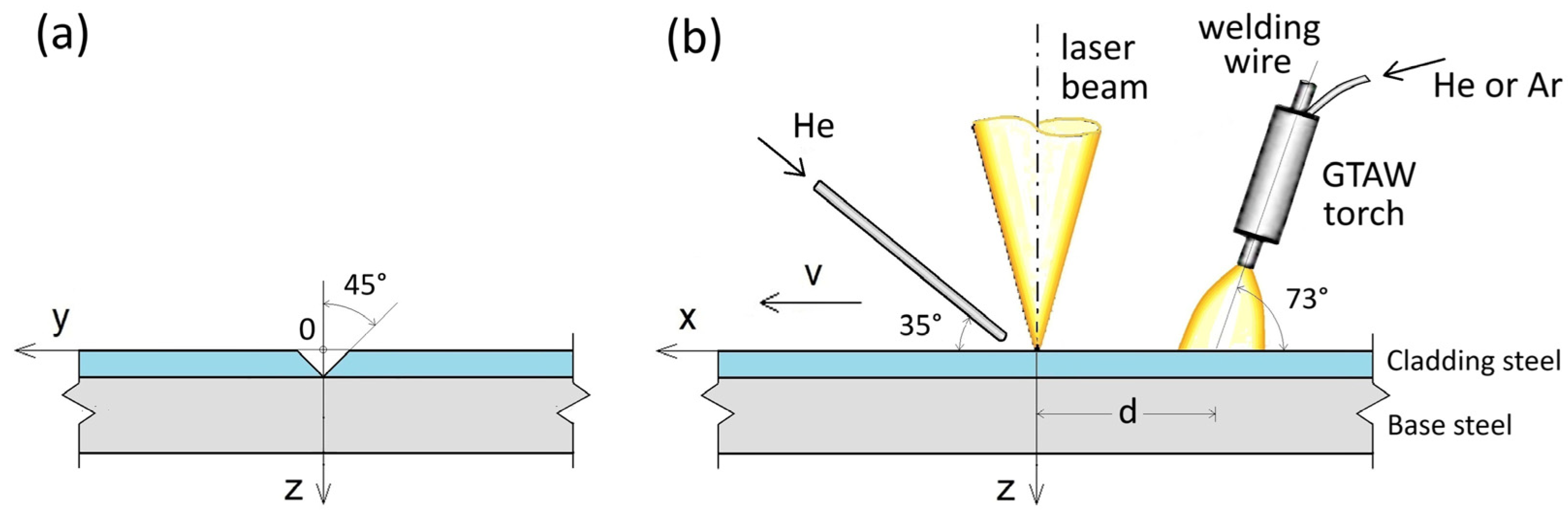
2.2. Process Setup
2.3. Welding Parameters
2.4. Experimental Methods
2.5. Theoretical Modeling of Thermal Fields
3. Results
3.1. Visual Inspection and Macrographic Observations
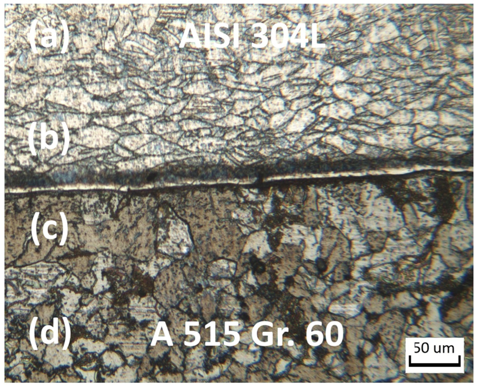
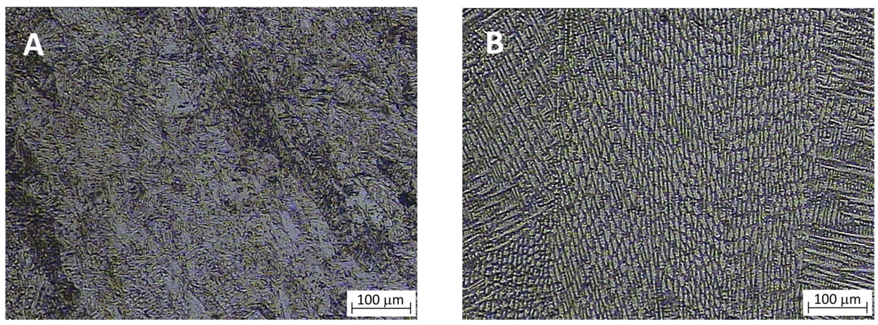
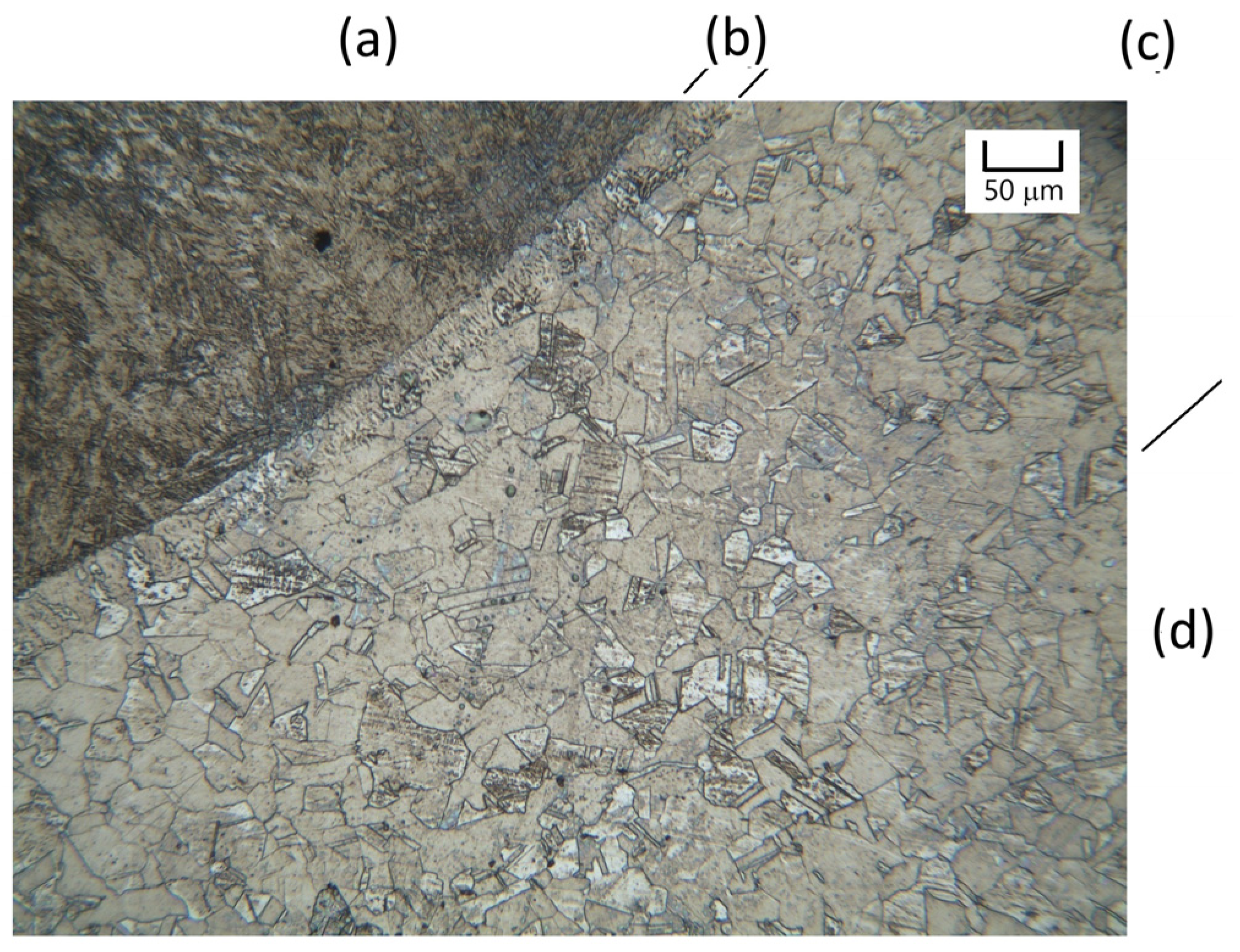
3.2. Optical Microscopy Observations and Vickers Test

| Microhardness (HV) | Specimen A FZ (Along the Weld Centerline) | Specimen A HAZ (on the Carbon Steel Side) | Specimen B FZ (Along the Weld Centerline) | Specimen B HAZ (on the Carbon Steel Side) |
|---|---|---|---|---|
| Range | 370–410 | 317–345 | 150–160 | 155–170 |
| Average value | 394 | 330 | 153 | 164 |
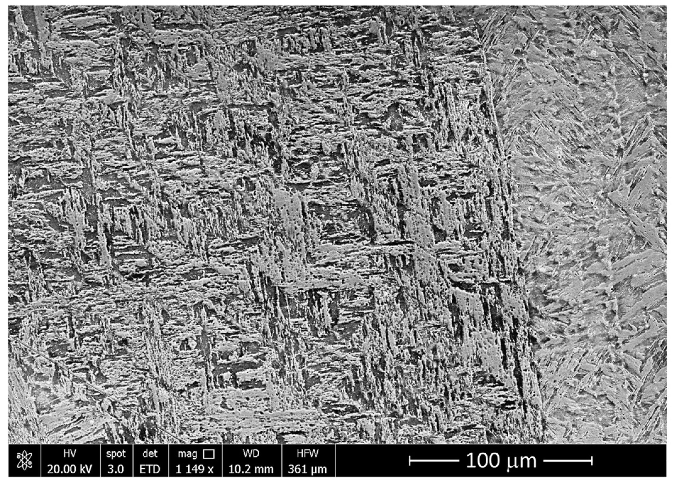
3.3. SEM-EDS Observations
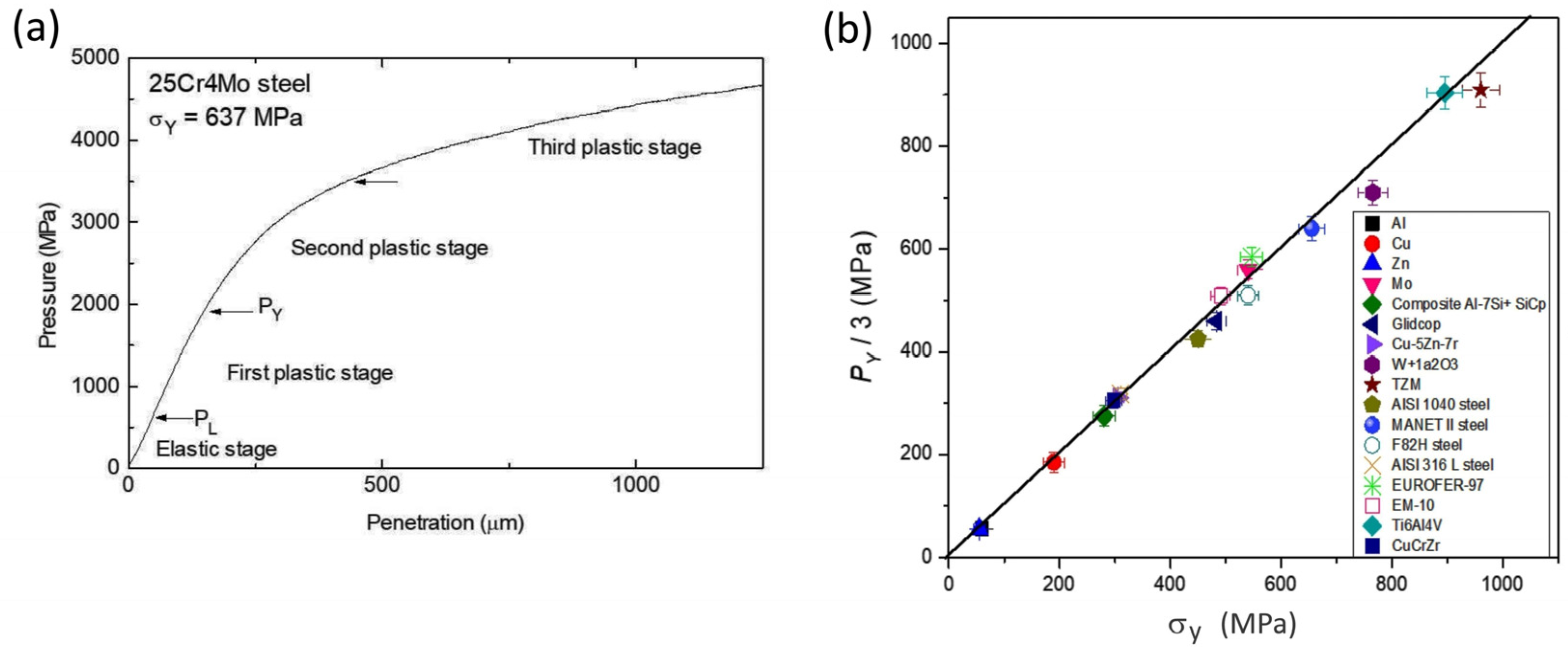
3.4. FIMEC Test
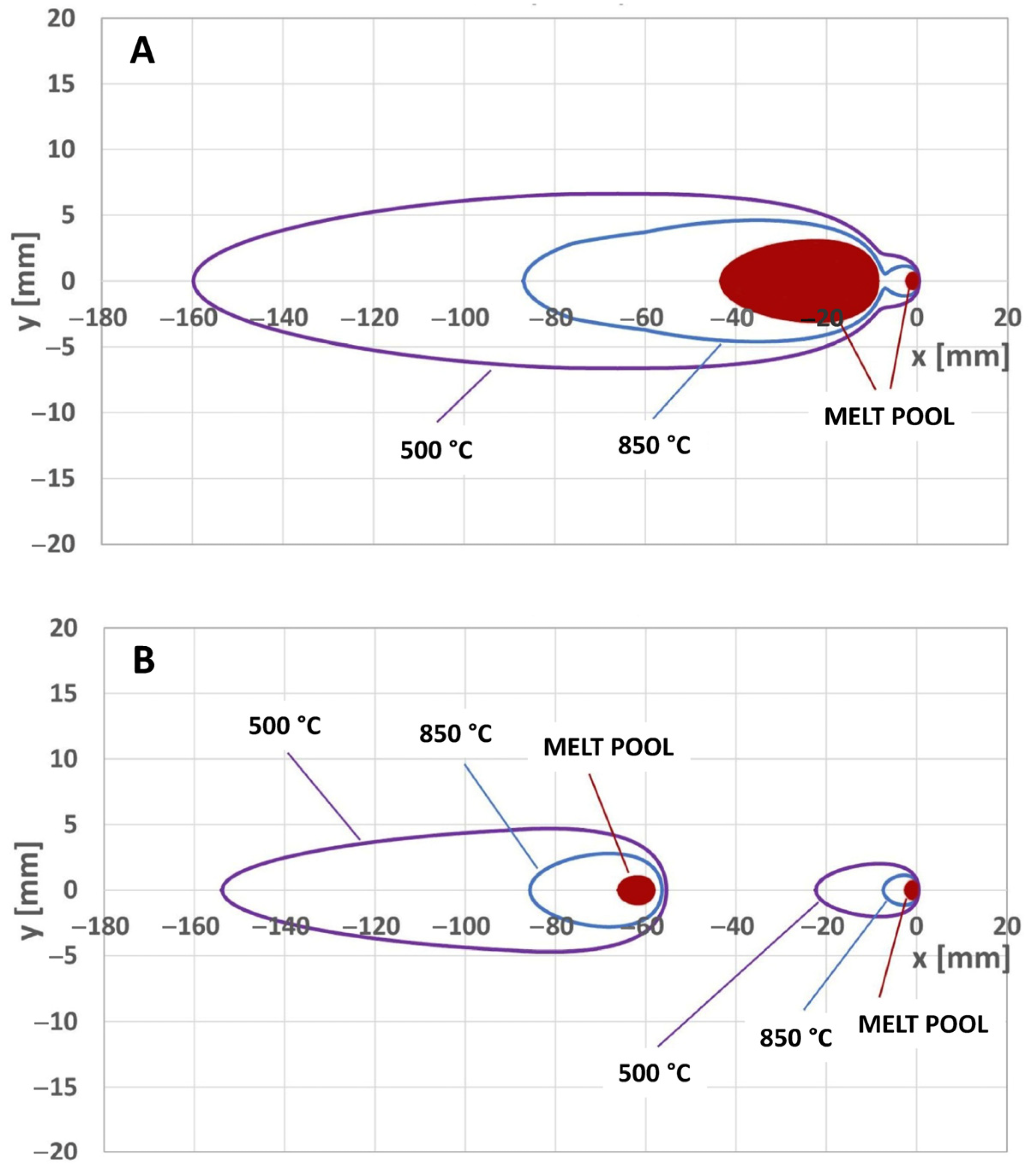
3.5. Thermal Field Simulation
- Procedure A—one point source on the surface at zP1 = 0 mm and the other one at zP2 = 4 mm, with the total power of the electric arc (11.7 kW from Table 2) divided between the two sources according the ratio QP1/QP2 = 1.86, that is QP1 = 7.61 kW and QP2 = 4.09 kW;
- Procedure B—one point source on the surface at zP1 = 0 mm, and the other one at zP2 = 3 mm, with the total power of the electric arc (18.1 kW from Table 2) divided according the ratio QP1/QP2 = 2.34, that is QP1 = 12.68 kW and QP2 = 5.42 kW.
4. Discussion
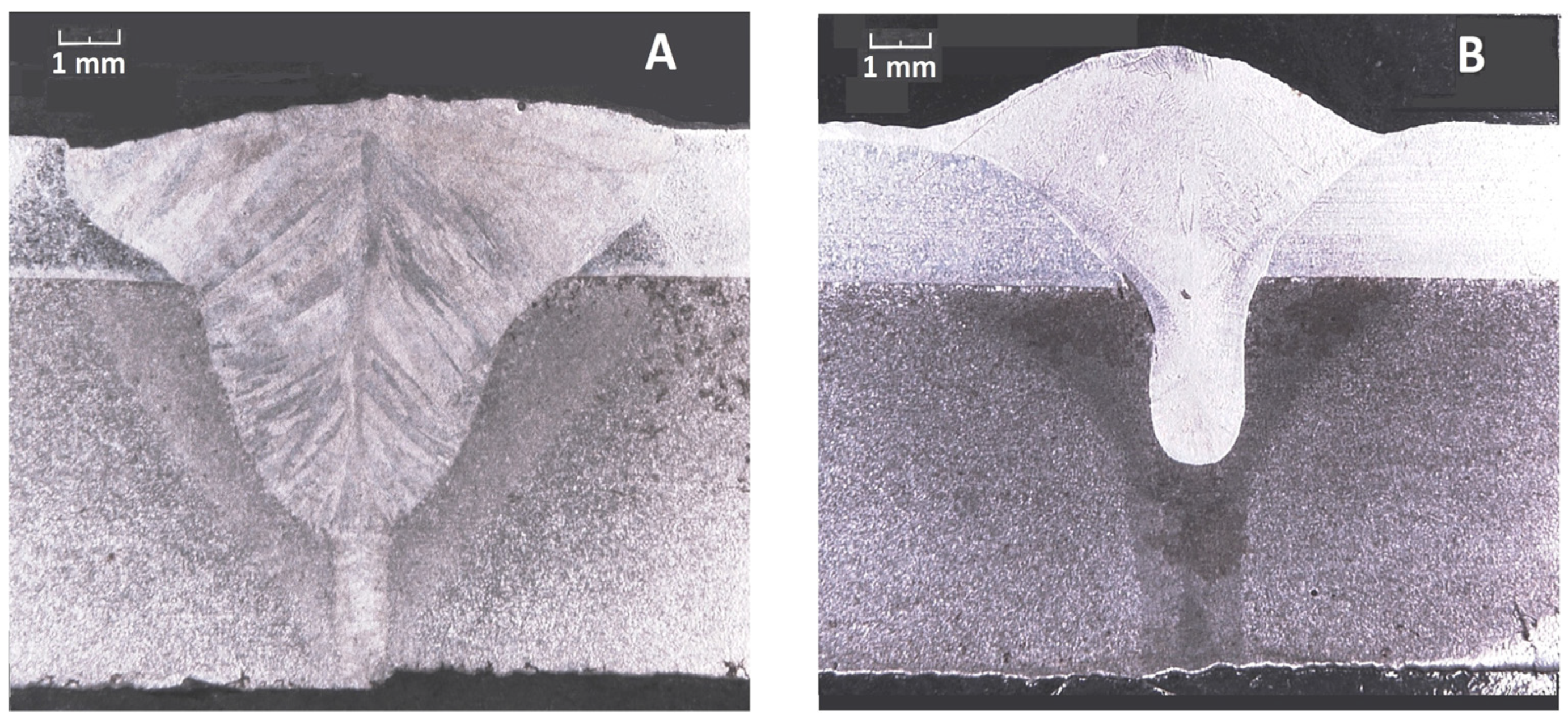
- In the cross section of specimen A, obtained by working with d = 8 mm, the electric arc gives rise to a FZ with a large extension predominantly on the cladding layer level (orange outline); approaching the weld root, the FZ gradually reduces until the action of the electric arc runs out. Finally, the last zone before the root maintains the shape of the first weld carried out under the keyhole condition due to the laser beam (green outline);
- In specimen B, the welded section produced by electric arc has a smaller and shallower extension, since it benefits, to a limited extent, from the thermal field produced by the laser beam because of the high inter-distance d = 55 mm. In this case, the alloying process takes place with the prevalent contribution of the filler and the cladding layer, and the shape of the first weld made by the laser beam is maintained for a greater length than that observed in specimen A.
5. Conclusions
Author Contributions
Funding
Data Availability Statement
Conflicts of Interest
References
- Bunaziv, I.; Akselsen, O.M.; Frostevarg, J.; Kaplan, A.F.H. Application of laser-arc hybrid welding of steel for low temperature service. Int. J. Adv. Manuf. Techol. 2019, 102, 2601–2613. [Google Scholar] [CrossRef]
- Tang, G.; Zhao, X.; Li, R.; Liang, Y.; Jiang, Y.; Chen, H. The effect of arc position on laser-arc hybrid welding of 12-mm-thick high strength bainitic steel. Opt. Laser Technol. 2020, 121, 105780. [Google Scholar] [CrossRef]
- Acherjee, B. Laser arc hybrid welding. In Advances in Laser Materials Processing: Technology, Research and Applications, 2nd ed.; Lawrence, J.R., Ed.; Woodhead Publishing: Cambridge, UK, 2018; pp. 203–234. [Google Scholar]
- Bunaziv, I.; Dørum, C.; Nielsen, S.E.; Suikkanen, P.; Ren, X.; Nyhus, B.; Eriksson, M.; Akselsen, O.M. Laser-arc hybrid welding of 12- and 15-mm thick structural steel. Int. J. Adv. Manuf. Techol. 2020, 107, 2649–2669. [Google Scholar] [CrossRef]
- Kim, S.H.; Kim, J.-D.; Jun, H.-U.; Cheon, J.-Y.; Yun, S.; Kim, Y.; Ji, C. A review on effects of weld porosity in laser-arc hybrid welding for aluminum alloys. J. Weld. Join. 2023, 41, 358–366. [Google Scholar] [CrossRef]
- Urbanczy, M.; Adamiec, J. Hybrid welding (Laser–Electric Arc MAG) of high yield point steel S960QL. Materials 2021, 14, 5447. [Google Scholar] [CrossRef]
- Kah, P. Overview of the exploration status of laser-arc hybrid welding processes. Rev. Adv. Mater. Sci. 2012, 30, 112–132. [Google Scholar]
- Gook, S.; El-Batahgy, A.-M.; Gumenyuk, A.; Biegler, M.; Rethmeier, M. Application of hybrid laser arc welding for construction of LNG tanks made of thick cryogenic 9% Ni steel plates. Lasers Manuf. Mater. Process 2023, 10, 659–680. [Google Scholar] [CrossRef]
- Zhan, X.; Wu, Y.; Kang, Y.; Liu, X.; Chen, X. Simulated and experimental studies of laser-MIG hybrid welding for plate-pipe dissimilar steel. Int. J. Adv. Manuf. Technol. 2019, 101, 1611–1622. [Google Scholar] [CrossRef]
- Zhang, L.; Peng, G.; Chi, J.; Bi, J.; Yuan, X.; Li, W.; Zhang, L. Effect of process parameters on the formability, microstructure, and mechanical properties of laser-arc hybrid welding of Q355B steel. Materials 2023, 16, 4253. [Google Scholar] [CrossRef]
- Brunner-Schwer, C.; Ustundag, O.; Bakir, N.; Gumenyuk, A.; Rethmeier, M. Process advantages of laser hybrid welding compared to conventional arc-based welding processes for joining thick steel structures of wind tower. IOP Conf. Ser. Mater. Sci. Eng. 2023, 1296, 012028. [Google Scholar] [CrossRef]
- Bunaziv, I.; Ren, X.; Olden, V. A comparative study of laser-arc hybrid welding with arc welding for fabrication of offshore substructures. J. Phys. Conf. Ser. 2023, 2626, 012033. [Google Scholar] [CrossRef]
- Abilash, M.; Senthil Kumar, D.; Padmanabham, G.; Padmanaban, P.R.; Thirumalini, S. The effect of welding direction in CO2 LASER—MIG hybrid welding of mild steel plates. IOP Conf. Ser. Mater. Sci. Eng. 2016, 149, 012031. [Google Scholar] [CrossRef]
- Kah, P.; Salminen, A.; Martikainen, J. The effect of the relative location of laser beam with arc in different hybrid welding processes. Mechanicka 2010, 83, 68–74. [Google Scholar]
- Chen, Y.; Yang, Z.; Xu, K.; He, P.; Shi, M.; Chen, S.; Fang, C. Effect of energy parameters on droplet transfer behavior and weld formation in laser-arc hybrid welding with cable-type welding wire. J. Mater. Res. Technol. 2023, 26, 4191–4205. [Google Scholar] [CrossRef]
- Ning, J.; Na, S.-J.; Wang, C.H.; Zhang, L.-J. A comparison of laser-metal inert gas hybrid welding and metal inert gas welding of high nitrogen austenitic stainless steel. J. Mater. Res. Technol. 2021, 13, 1841–1854. [Google Scholar] [CrossRef]
- Yang, S.; Yang, L.; Wang, D.; Zhang, F.; Liu, C.; Huang, G. Effect of welding stability on process porosity in laser arc hybrid welding of dissimilar steel. Optik 2022, 271, 170165. [Google Scholar] [CrossRef]
- Silva, R.G.N.; de Paço, C.M.M.; Rodrigues, M.B.; Sá de Sousa, J.M.; Pereira, M.; Ramos, B.B.; Barancelli Schwedersky, M.; Gonçalves e Silva, R.H. A comparison between LBW and hybrid laser-GMAW processes based on microstructure and weld geometry for hardenable steels. Int. J. Adv. Manuf. Techol 2020, 110, 2801–2814. [Google Scholar] [CrossRef]
- Frostevarg, J.; Kaplan, A.F.H. Undercut suppression in laser-arc hybrid welding by melt pool tailoring. J. Laser Appl. 2014, 26, 031501. [Google Scholar] [CrossRef]
- Kang, K.; Kawahito, Y.; Gao, M.; Zeng, X. Effects of laser-arc distance on corrosion behavior of single-pass hybrid welded stainless clad steel plate. Mater. Des. 2017, 123, 80–88. [Google Scholar] [CrossRef]
- Gao, M.; Zeng, X.Y.; Hu, Q.W. Effects of welding parameters on melting energy of CO2 laser–GMA hybrid welding. Sci. Technol. Weld. Joi 2006, 11, 517–522. [Google Scholar] [CrossRef]
- Bunaziv, I.; Frostevarg, J.; Akselsen, O.M.; Kaplan, A.F.H. Process stability during fiber laser-arc hybrid welding of thick steel plates. Opt. Laser Eng. 2018, 3, 34–44. [Google Scholar] [CrossRef]
- Gao, Y.; Zhang, Y.; Li, J.; Liu, K.; Xu, Y.; Zhou, J.-P. Research on the performance of laser-MIG arc tandem welding of CP-Ti/304 stainless steel bimetallic sheets. Mater. Lett. 2021, 305, 130805. [Google Scholar] [CrossRef]
- DebRoy, T.; Elmer, J.W. Metals beyond tomorrow: Balancing supply, demand, sustainability, substitution, and innovations. Mater. Today 2024, 80, 737–757. [Google Scholar] [CrossRef]
- Costanza, G.; Crupi, V.; Guglielmino, E.; Sili, A.; Tata, M.E. Metallurgical characterization of an explosion welded aluminum/steel joint. Met. Ital. 2016, 108, 17–22. [Google Scholar]
- Giudice, F.; Missori, S.; Murdolo, F.; Sili, A. Metallurgical characterization of the interfaces in steel plates clad with austenitic steel or high Ni alloys by hot rolling. Metals 2020, 10, 286. [Google Scholar] [CrossRef]
- Yu, W.X.; Liu, B.X.; Chen, C.X.; Liu, M.Y.; Zhang, X.; Fang, W.; Ji, P.G.; He, J.N.; Yin, F.X. Microstructure and mechanical properties of stainless steel clad plate welding joints by different welding processes. Sci. Technol. Weld. Join. 2020, 25, 571–580. [Google Scholar] [CrossRef]
- Ban, H.; Yang, X.; Shi, Y.; Chung, K.-F.; Hu, Y.-F. Micro-macro properties of stainless-clad bimetallic steel welded connections with different configurations. J. Constr. Steel Res. 2024, 217, 108637. [Google Scholar] [CrossRef]
- Missori, S.; Sili, A. Prediction of weld metal microstructure in laser beam welded clad steel. Metallurgist 2018, 62, 84–92. [Google Scholar] [CrossRef]
- Reutzel, E.W.; Kelly, S.M.; Sullivan, M.J.; Huang, T.D.; Kvidahl, L.; Martukanitz, R.P. Hybrid laser-GMA welding for improved affordability. J. Ship Prod. 2008, 24, 72–81. [Google Scholar] [CrossRef]
- Giudice, F.; Missori, S.; Scolaro, C.; Sili, A. A Review on metallurgical issues in the production and welding processes of clad steels. Materials 2024, 17, 4420. [Google Scholar] [CrossRef]
- Gupta, A.; Singh, J.; Chhibber, R. Dissimilar welding of austenitic and ferritic steels using nickel and stainless-steel filler: Associated issues. P. I Mech. Eng. E-J. Pro 2023, 238, 2524–2544. [Google Scholar] [CrossRef]
- Giudice, F.; Missori, S.; Sili, A. Parameterized multipoint-line analytical modeling of a mobile heat source for thermal field prediction in laser beam welding. Int. J. Adv. Manuf. Technol. 2021, 112, 1339–1358. [Google Scholar] [CrossRef]
- Bunaziv, I.; Akselsen, O.M.; Frostevarg, J.; Kaplan, A.F.H. Laser-arc hybrid welding of thick HSLA steel. J. Mater. Process Technol. 2018, 259, 75–87. [Google Scholar] [CrossRef]
- Katayama, S.; Kawahito, Y.; Mizutani, M. Elucidation of laser welding phenomena and factors affecting weld penetration and welding defects. Phys. Procedia 2010, 5, 9–17. [Google Scholar] [CrossRef]
- Yang, S.; Wang, D.; Yang, L.; Zhang, F.; Zhang, C.; Zhou, B.; Liu, C.; Huang, G. Effects of laser-arc hybrid welding on microstructure and mechanical properties of dissimilar steel joint. Optik 2022, 268, 169795. [Google Scholar] [CrossRef]
- Eriksson, I.; Powell, J.; Kaplan, A. Guidelines in the choice of parameters for hybrid laser arc welding with fiber lasers. Phys. Procedia 2013, 41, 119–127. [Google Scholar] [CrossRef]
- Acherjee, B. Hybrid laser arc welding: State-of-art review. Opt. Laser Technol. 2018, 99, 60–71. [Google Scholar] [CrossRef]
- Montanari, R.; Varone, A. Flat-top cylinder indenter for mechanical characterization: A report of industrial applications. Materials 2021, 14, 1742. [Google Scholar] [CrossRef]
- Rosenthal, D. The theory of moving sources of heat and its application to metal treatments. Trans. ASME 1946, 68, 849–866. [Google Scholar] [CrossRef]
- Dowden, J.M. The Mathematics of Thermal Modelling: An Introduction to the Theory of Laser Material Processing; Chapman & Hall/CRC: Boca Raton, FL, USA, 2001. [Google Scholar]
- Nasiri, M.B.; Enzinger, N. Powerful analytical solution to heat flow problem in welding. Int. J. Therm. Sci. 2019, 135, 601–612. [Google Scholar] [CrossRef]
- Franco, A.; Romoli, L.; Musacchio, A. Modelling for predicting seam geometry in laser beam welding of stainless steel. Int. J. Therm. Sci. 2014, 79, 194–205. [Google Scholar] [CrossRef]
- Giudice, F.; Sili, A. Validation of a theoretical model for laser welding thermal field by multi-physics numerical simulation. Metals 2023, 13, 2020. [Google Scholar] [CrossRef]
- Meng, Y.; Kang, K.; Gao, M.; Zeng, X. Relationship between corrosion resistance and microstructure characteristic of single-pass laser-arc hybrid welded stainless clad steel plate. Met. Mater. Trans. A 2019, 50, 2817–2825. [Google Scholar] [CrossRef]
- ISO 13919-1:2019; Electron and Laser-Beam Welded Joints—Requirements and Recommendations on Quality Levels for Imperfections—Part 1: Steel, Nickel, Titanium and Their Alloys. ISO International Organization for Standardization: Geneva, Switzerland, 2019.
- Li, H.; Zhang, L.; Zhang, B.; Zhang, Q. Microstructure characterization and mechanical properties of stainless steel clad plate. Materials 2019, 12, 509. [Google Scholar] [CrossRef] [PubMed]
- Fulong, Z.; Beibei, M.; Shuangyu, L.; Bo, C.; Fengde, L.; Guochang, L.; Wei, R.; Hong, Z. Effect of a nickel-based alloy cladding layer on the strength and toughness of the high-strength steel laser-MAG hybrid welding joint. Mater. Res. Express 2020, 7, 076501. [Google Scholar] [CrossRef]
- Li, X.; Zhang, H. Analysis of microstructure and properties of welded joint of high nitrogen steel by hybrid welding. Mater. Res. Express 2019, 6, 045602. [Google Scholar] [CrossRef]
- Cao, J.; Wang, Y.; Liu, X.; Xu, G.; Zeng, X.; Wei, K. Single-pass high-power laser-Arc hybrid welding of thick stainless steel clad plates: Microstructure and mechanical properties. J. Mater. Res. Technol. 2024, 30, 5733–5745. [Google Scholar] [CrossRef]
- Di Siena, M.; Genna, S.; Moretti, P.; Ponticelli, G.S.; Venettacci, S.; Russo, P. Study of the laser-material interaction for innovative hybrid structures: Thermo-mechanical characterization of polyethylene-based polymers. Polym. Test. 2023, 120, 107947. [Google Scholar] [CrossRef]
- Brutti, C. A theoretical model for elastic-perfectly plastic flat cylindrical punch indentation. Mech. Mater. 2021, 155, 103770. [Google Scholar] [CrossRef]
- Han, G.; Cai, L.; Xiao, H.; Huang, M. A novel flat indentation test method for obtaining stress–strain relationships of metallic materials based on energy density equivalence. Int. J. Solids Struct. 2023, 269, 112195. [Google Scholar] [CrossRef]
- Gondi, P.; Donato, A.; Montanari, R.; Sili, A. A miniaturized test method for the mechanical characterization of structural materials for fusion reactors. J. Nucl. Mater. 1996, 233–237, 1557–1560. [Google Scholar] [CrossRef]
- Mills, K.C. Recommended Values of Thermophysical Properties for Selected Commercial Alloys; Woodhead Publishing: Cambridge, UK, 2002. [Google Scholar]
- Miettinen, J.; Louhenkilpi, S. Calculation of thermophysical properties of carbon and low alloyed steels for modelling of solidification processes. Met. Mater. Trans. B 1994, 25, 909–916. [Google Scholar] [CrossRef]
- Bunaziv, I.; Frostevarg, J.; Akselsen, O.M.; Kaplan, A.F.H. The penetration efficiency of thick plate laser-arc hybrid welding. Int. J. Adv. Manuf. Technol. 2018, 97, 2907–2919. [Google Scholar] [CrossRef]
- Landowski, M.; Swierczynska, A.; Rogalski, G.; Fydrych, D. Autogenous fiber laser welding of 316L austenitic and 2304 lean duplex stainless steels. Materials 2020, 13, 2930. [Google Scholar] [CrossRef]
- Bunaziv, I.; Ren, X.; Hagen, A.B.; Hovig, E.W.; Jevremovic, I.; Dahl, S.G. Laser beam remelting of stainless steel plate for cladding and comparison with conventional CMT process. Int. J. Adv. Manuf. Technol. 2023, 127, 911–934. [Google Scholar] [CrossRef]
- Bunaziv, I.; Olden, V.; Akselsen, O.M. Metallurgical aspects in the welding of clad pipelines—A global outlook. Appl. Sci. 2019, 9, 3118. [Google Scholar] [CrossRef]


| Materials | C | Mn | Si | P | S | Cr | Ni | Mo | Cu | Fe | |
|---|---|---|---|---|---|---|---|---|---|---|---|
| Plate substrate | ASTM A515 Gr.60 | 0.145 | 0.85 | 0.20 | 0.008 | 0.001 | - | - | - | - | Bal. |
| Plate cladding | AISI 304L | 0.017 | 1.32 | 0.39 | 0.029 | 0.003 | 18.39 | 10.07 | - | - | Bal |
| Welding wire | DIN 1.4562 (X1NiCrMoCu 32-28-7) | 0.014 | 1.67 | 0.03 | - | - | 27.24 | 29.29 | 6.05 | 1.02 | Bal. |
| Procedure A (d = 8 mm) | Procedure B (d = 55 mm) | |
|---|---|---|
| LBW | ||
| Power (kW) | 5 | 5 |
| Focal diameter (mm) | 0.5 | 0.5 |
| Defocusing (mm) | 0 | 0 |
| Distance beam/arc (mm) | 8 | 55 |
| Shielding gas (L/min) | (1) | 30 (He) |
| Welding speed (m/s) | 0.02 | 0.02 |
| GMAW | ||
| Voltage (V) | 38.2 | 38.3 |
| Current (A) | 307 | 472 |
| Power (kW) | 11.7 | 18.1 |
| Wire diameter (mm) | 1.2 | 1.2 |
| Wire feeding rate (m/s) | 0.25 | 0.25 |
| Shielding gas (L/min) | 60 (He) | 15 (Ar) |
| Cumulative parameters | ||
| LBW/GMAW power ratio | 5/11.7 = 0.43 | 5/18.1 = 0.28 |
| LBW + GMAW power (kW) | 16.7 | 23.1 |
| Welding speed (m/s) | 0.02 | 0.02 |
| Total heat input (kJ/m) | 835 | 1150 |
| Microhardness (HV) | AISI 304 L (Far from the Cladding Line) | AISI 304L (Sensitized Zone) | A 515 Gr. 60 (Far from the Cladding Line) | A 515 Gr. 60 (Decarburized Zone) |
|---|---|---|---|---|
| Range | 179–204 | 248–264 | 131–145 | 122–138 |
| Average value | 198 | 254 | 143 | 132 |
| ASTM A515 Base Metal (Far from Weld) | AISI 304L Cladding Layer (Far from Weld) | FZ Specimen A (Weld Center) | FZ Specimen B (Weld Center) | |
|---|---|---|---|---|
| σY = PY/3 (MPa) | 928/3 = 309 | 976/3 = 325 | 2723/3 = 907 | 1345/3 = 448 |
| Material | Density ρ (kg/m3) | Specific Heat CP (J/kg°C) | Conductivity k (W/m°C) | Diffusivity α = k/ρCP (m2/s) | Melting Temp. Tm (°C) |
|---|---|---|---|---|---|
| AISI 304 L | 7682 | 600 | 25 | 5.42 · 10−6 | 1400 |
| ASTM A515 Gr.60 | 7650 | 768 | 28 | 4.76 · 10−6 | 1510 |
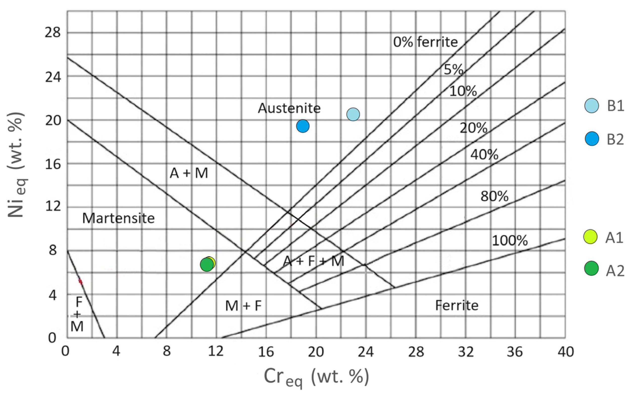
| A1 | A2 | B1 | B2 | |
|---|---|---|---|---|
| Nieq | 6.8 | 6.63 | 20.51 | 19.51 |
| Creq | 11.48 | 11.27 | 22.9 | 18.7 |
Disclaimer/Publisher’s Note: The statements, opinions and data contained in all publications are solely those of the individual author(s) and contributor(s) and not of MDPI and/or the editor(s). MDPI and/or the editor(s) disclaim responsibility for any injury to people or property resulting from any ideas, methods, instructions or products referred to in the content. |
© 2025 by the authors. Licensee MDPI, Basel, Switzerland. This article is an open access article distributed under the terms and conditions of the Creative Commons Attribution (CC BY) license (https://creativecommons.org/licenses/by/4.0/).
Share and Cite
Costanza, G.; Giudice, F.; Missori, S.; Scolaro, C.; Sili, A.; Tata, M.E. Weldability Assessment of Austenitic/Ferritic Clad Plates Joined by a Combined Laser Beam–Electric Arc Process. J. Manuf. Mater. Process. 2025, 9, 90. https://doi.org/10.3390/jmmp9030090
Costanza G, Giudice F, Missori S, Scolaro C, Sili A, Tata ME. Weldability Assessment of Austenitic/Ferritic Clad Plates Joined by a Combined Laser Beam–Electric Arc Process. Journal of Manufacturing and Materials Processing. 2025; 9(3):90. https://doi.org/10.3390/jmmp9030090
Chicago/Turabian StyleCostanza, Girolamo, Fabio Giudice, Severino Missori, Cristina Scolaro, Andrea Sili, and Maria Elisa Tata. 2025. "Weldability Assessment of Austenitic/Ferritic Clad Plates Joined by a Combined Laser Beam–Electric Arc Process" Journal of Manufacturing and Materials Processing 9, no. 3: 90. https://doi.org/10.3390/jmmp9030090
APA StyleCostanza, G., Giudice, F., Missori, S., Scolaro, C., Sili, A., & Tata, M. E. (2025). Weldability Assessment of Austenitic/Ferritic Clad Plates Joined by a Combined Laser Beam–Electric Arc Process. Journal of Manufacturing and Materials Processing, 9(3), 90. https://doi.org/10.3390/jmmp9030090