Article

Enhancing Micro-Milling Performance of Ti6Al4V: An Experimental Analysis of Ultrasonic Vibration Effects on Forces, Surface Topography, and Burr Formation

by
Asmaa Wadee
1,*,
Mohamed G. A. Nassef
1,2,
Florian Pape
3,* and
Ibrahem Maher
1,4
1
Industrial and Manufacturing Engineering Department, Egypt-Japan University of Science and Technology, New Borg El Arab City 21934, Egypt
2
Production Engineering Department, Faculty of Engineering, Alexandria University, Alexandria 21544, Egypt
3
Institute of Machine Design and Tribology, Leibniz University of Hanover, 30167 Hannover, Germany
4
Mechanical Engineering Department, Faculty of Engineering, Kafrelsheikh University, Kafrelsheikh 33516, Egypt
*
Authors to whom correspondence should be addressed.
J. Manuf. Mater. Process. 2025, 9(11), 356; https://doi.org/10.3390/jmmp9110356
Submission received: 3 October 2025 / Revised: 24 October 2025 / Accepted: 28 October 2025 / Published: 30 October 2025
(This article belongs to the Special Issue Advances in Micro Machining Technology)

Abstract

The current study focuses on axial ultrasonic vibration-assisted micro-milling as an advanced technique to improve the machining performance of Ti6Al4V, a material whose difficult-to-cut properties present a significant barrier to manufacturing the high-quality micro-components essential for aerospace and biomedical applications. A full factorial design was employed to evaluate the influence of feed-per-tooth (fz), axial depth-of-cut (ap), and ultrasonic vibration on cutting forces, surface roughness, burr formation, and tool wear. Experimental results demonstrate that ultrasonic assistance significantly reduces cutting forces by 20.09% and tool wear by promoting periodic tool–workpiece separation and improving chip evacuation. However, it increases surface roughness due to the formation of uniform micro-dimples, which may enhance tribological properties. Burr dimensions were primarily governed by feed-per-tooth, with higher feeds minimizing burr size. The study provides actionable insights into optimizing machining parameters for cutting Ti6Al4V, highlighting the trade-offs between force reduction, surface texture, and burr control. These findings contribute to advancing ultrasonic-assisted micro-milling for industrial applications, namely aerospace and biomedical applications requiring high precision and extended tool life.

1. Introduction

Recent growth in aerospace, medical, and oceanographic industries has increased demand for high-precision micro-components with superior surface quality and assembly accuracy. Miniaturized components can be produced using various micro-machining technologies such as electro-discharge machining, laser micro-manufacturing, lithography–electroplating, and moulding (LIGA), deep reactive-ion etching, deep UV lithography, and mechanical micro-machining. These methods allow for the achievement of precise geometrical features and small tolerances, but they often come with high operation time and cost [1]. Among these technologies, mechanical micro-machining stands out as a time-effective and cost-effective method for manufacturing miniaturized 3D components, primarily due to its relatively high material removal rate. This approach involves the creation of micro 3D features utilizing endmills with a diameter of 1000 µm or smaller. These endmills are typically operated at high cutting speeds, with minimal feed-per-tooth and a shallow depth-of-cut. However, the micro-milling process is often linked to a multitude of challenges, as evidenced by the findings of Roushan et al. Micro-milling processes are vulnerable to accelerated tool deterioration and premature failure due to the fragile nature of the cutting tool, repetitive cyclical loads, tool deformation, vibration, and mechanical stress [2]. The small cross-section makes the wear and breakage of the tool one of the main limitations of micro-milling [3]. Micro-milling poses challenges such as the generation of burrs, the presence of residual stress, reduced accuracy due to rapid tool wear, and size effect [4]. The size effect is characterized by how the ratio of the uncut chip thickness (UCT) to the cutting-edge radius of the tool affects chip formation, material removal mechanisms, and material flow [5]. The minimum uncut chip thickness hmin typically ranges from one-fourth to one-third of the cutting-edge radius of the tool [6]. If the UCT is below the critical value hmin, the chip will be compressed by the cutting-edge radius, resulting in ploughing as the primary mechanism for material removal. This process leads to the formation of large burrs, increased cutting forces, and a rough surface finish. Conversely, when the UCT surpasses hmin, chip formation shifts towards shearing with reduced ploughing. The thickness of the uncut chip is primarily determined by the feed-per-tooth value fz. In full-immersion slot milling, the undeformed chip thickness goes from zero to the maximum hmax = fz and then returns to zero. In macroscale cutting, the feed-per-tooth is significantly greater than hmin, resulting in chip formation through shearing when UCT is higher than hmin. Conversely, micro-milling involves a much lower feed-per-tooth, potentially preventing the minimum uncut chip thickness from being reached during the chip formation process. In addition, this low feed leads to ploughing by using negative tool effective rake angle, leading to increased cutting forces and a decrease in surface quality [6]. The minimum chip thickness phenomenon serves as a distinguishing factor between macro- and micro-scale milling processes [7]. Therefore, it is essential to determine the appropriate cutting conditions based on the cutting-tool specifications, workpiece material and microstructure, and machining parameters. To tackle the identified issues, numerous articles in the literature explored the impact of different machining parameters to improve the performance in micro-milling, particularly for difficult-to-cut materials. The early work of Wang et al. [8] studied the chip formation mechanism using a numerical model with one-flute endmills in the finite-element method (FEM). Li and Chou [9] found that a tool feed-per-tooth comparable to the tool radius results in a negative effective rake angle. This detrimental geometry, in turn, leads to increased burrs and accelerated tool wear. Kumar and Bajpai [10] performed an extensive experimental study to test the effect of feed-per-tooth and depth-of-cut on surface roughness and top burrs. Statistical analysis revealed that the increase in the feed-per-tooth or depth-of-cut significantly reduced the top-burr width in down-milling side, while the high feed-per-tooth has larger impact with respect to depth-of-cut on increasing surface roughness. In their research, Silva and da Silva [11] explored how various tool diameters and cutting speeds influence the micro-milling process of UNS S32205 duplex stainless steel. The results revealed that utilizing a larger endmill diameter of 400 µm led to diminished tool wear and a reduction in burr formation when compared with the smaller 200 µm diameter. Yadav et al. [12] utilized an analytical framework to examine the occurrence of burrs in the micro-milling processes of Ti-6Al-4V, Al-6061, and OFHC-Cu. The simulations conducted via FEM allowed them to determine the minimum undeformed chip thickness. de Oliveira et al. [13] explored the different types of chips generated during the micro-milling process of Inconel 718, utilizing both experimental methods and theoretical frameworks based on FEM. The results from the computational analysis demonstrated that helicoidal chips are produced through effective cutting at the main cutting edge, whereas the ribbon chips are formed due to the action of the minor cutting edge.
Titanium (Ti) and its alloys are considered one of the most popular material groups in modern aerospace and biomedical applications [14]. Among the various grades of titanium, Ti6Al4V (Grade 5 titanium alloy) is popular among all titanium alloys due to its light weight compared to high strength, corrosion resistance, and biocompatibility, which make it particularly suited for implants and dental applications, including crowns and dentures [15]. However, Ti6Al4V is a difficult-to-machine material with a strong affinity for tool materials and low thermal conductivity, leading to rapid tool wear [16]. Recent research has emphasized that micro-scale machining performance is highly sensitive to kinematic precision and process parameter selection. LV et al. [17] demonstrated that even small variations in feed and depth of cut, combined with spindle motion errors, can markedly influence surface residual height and dimensional accuracy in micro-milling. Such findings highlight the necessity of precise control over cutting parameters and vibration conditions, particularly when machining hard-to-cut alloys like Ti–6Al–4V. Conventional micromachining processes, such as micro-turning, micro-milling, micro-grinding, and micro-drilling have been found to be challenging for machining most of the titanium alloys [14]. In attempt to overcome this limitation, Ziberov et al. [18] reported that tool coating and coolant significantly impact Ti6Al4V micro-milling. Diamond-like carbon (DLC)-coated tools lasted 640% longer than TiAlN-coated tools. Conversely, cutting fluids improved surface quality at the cost of tool life, which was less in dry cutting due to the protective built-up edge (BUE) effect. Roushan et al. [19] analyzed the consequences of changing tool diameters, spindle speeds, feed rates, and axial depth-of-cut. It was observed that as the feed rate increased, the surface roughness also increased while the cutting forces decreased. Similarly, the cutting force decreased with the decrease in tool diameter. In addition, Aslantas et al. [20] studied micro-milling for Ti6Al4V and Ti5333. The study revealed that the burr width increased by 2.5 and 1.75 on the down and up milling sides for Ti6Al4V compared to Ti5333, while no significant alterations in minimum chip thickness and cutting forces were observed when the alloy type was changed. Zhang et al. [21] suggested utilizing a spindle speed of 34,000 rpm, a moderate feed per tooth of 0.5 µm/z, and a depth of cut of 40 µm to attain a reduced surface roughness (Sa) during the slot micro-milling of Ti6Al4V. Wu et al. [22] conducted an extensive investigation to explore the formation mechanisms of various types of burrs in high-aspect-ratio slots (3:1) and (1.5:1) utilizing finite-element simulation. The research revealed that as the aspect ratio increases, the burr height also increases. Additionally, other research works focused on the use of various cooling and lubrication techniques to improve the machinability of Ti6Al4V. In the study by Wang et al. [23], a silicone oil was used to submerge the workpiece during machining to reduce chatter mitigation in comparison to the dry and flood regimes. The surface roughness of the workpiece was improved in the viscous fluid at the high depth of cuts compared to flood lubrication. The viscous fluid further reduced tool wear; however, it did not suppress the edge chipping. Hassanpour et al. [24] examined the impact of micro-milling parameters along with minimum lubrication (MQL) cooling on the reduction in cutting force and surface roughness of Ti6Al4V as well as burr width and hardness using analysis of variance (ANOVA). The results revealed that the most significant factor in reducing cutting force and surface roughness was the increase in spindle speed. The increase in feed-per-tooth was the most influential factor in the formation of micro burrs, with the burr width decreasing as the feed rate increased. Titanium is widely used in biomedical implants due to its high biocompatibility. Titanium facilitates the growth of osteoblasts within the cavities of the implants, while alternative metals permit the development of filamentous tissues, known as the membrane, solely around the implant, thereby diminishing the implant’s longevity. Ultrasonic-assisted machining is one of the methods effective in enhancing the tribological properties of the implant, as reported by Zamani et al. [25], who investigated the application of ultrasonic-assisted turning to fabricate micro-textures on titanium implants, aiming to enhance osteoblast cell adhesion, and they found that ultrasonic-textured surfaces exhibited stronger adhesion, with larger integrins and extended fibronectin compared to conventional turned surfaces. Zhu et al. [26] further investigated the micro-textured surface generation mechanism and tribological properties in ultrasonic vibration-assisted milling (UVAM) of Ti6Al4V. They found that ultrasonic generated textures enhance the surface quality and tribological performance of Ti6Al4V by generating uniform micro-textures, reducing friction, and improving wear resistance. The influence of the fish scale-like pattern on friction was studied by Pape and Poll [27]. The feasibility of applying relatively small-scale dimples for tribological contacts like roller bearings was shown by Pape et al. [28] and Kelley et al. [29].
Ultrasonic-assisted machining has shown great potential in improving the machinability of difficult-to-cut materials. This technique involves vibrating the tool or workpiece, with vibrations occurring in axial or torsional directions for the tool, and in-feed or elliptical directions for the workpiece. Ultrasonic tool vibration improves the machining process through several interconnected mechanisms: it lowers cutting forces, produces shorter chips, diminishes tool wear, and enhances workpiece accuracy and surface roughness, thereby making difficult-to-cut materials more manageable [30]. The acoustic softening effect of the ultrasonic waves has been found to decrease the material’s resistance to removal [31]. According to the literature, ultrasonic assistance can be one of the effective techniques to enhance micro-milling operations of hard to cut metallic alloys. However, the published work is scarce compared to macro-scale machining which is extensively studied. Yuan et al. [32] reported that the application of ultrasonic vibration in the feed direction of the workpiece during dry micro-milling of Inconel 718 led to a reduction in burr and chip size. In a similar study, Yuan et al. [33] found that the application of ultrasonic vibrations in the feed direction reduced the cutting forces at high feeds. Conversely, low feed rates resulted in higher cutting forces compared to conventional micro-milling. Additionally, it was noted that smaller amplitudes of 3 and 6 µm were found to reduce surface defects. In their investigation, Fang et al. [34] determined that ultrasonic assistance does not have a significant effect when the feed-per-tooth exceeds 4 µm during machining Inconel 718. The research conducted by Greco et al. [35] examined the effects of vibration-assisted micro-milling on additively manufactured 316L stainless steel with a vibration frequency of 5150 Hz. The incorporation of vibration assistance led to a decrease in both tool wear and the resultant forces; nevertheless, it was also associated with an increase in the generation of burrs. A study by Xu et al. [36] investigated the machining characteristics of titanium alloy (TC4) and aluminum alloy (Al6061) through micro-milling with in-feed ultrasonic vibrations. The results of the research demonstrated that ultrasonic vibration had a more significant influence on TC4 in terms of both force and surface roughness. Specifically, the milling force decreased by 12% for TC4 and 17% for Al6061. H13 tool steel. In their study, Lian et al. [37] explored the influence of ultrasonic assistance at different amplitudes on surface roughness during the micro-milling of Al6061. Their research demonstrated that by opting for the appropriate amplitude, it is feasible to lower surface roughness levels as opposed to utilizing traditional micro-milling methods. Using FEM and experiments for 316L stainless steel, Feng et al. [38] showed that ultrasonic-assisted micro-milling lowers cutting temperatures and breaks chips into fragments, unlike the continuous ribbons formed in traditional milling. Ullah et al. [39] investigated the impact of applying ultrasonic vibrations in feed direction during the micro-milling process of AISI 410 martensitic stainless steel. By varying the ultrasonic amplitude, they discovered that an increase to 3 µm significantly enhances process efficiency. Zhang et al. [40] investigated the mechanisms underlying burr formation during the ultrasonic-assisted micro-milling of Inconel 718 that when the ratio of vibration amplitude to feed-per-tooth (A/fz) exceeded 1/2, which is the criteria for the intermittent cutting condition. The incorporation of ultrasonic vibrations significantly diminished burr formation, with a greater reduction observed at higher vibration amplitudes. In their study, Satpute et al. [41] found that both 1D in feed and 2D feed axial vibrations led to a substantial reduction in surface roughness, achieving decreases of 144.26% and 106.61%, respectively, while also reducing tool wear compared to conventional techniques. Furthermore, a limited number of studies focused on testing the effect of implementation of different cooling techniques with ultrasonic assistance in micro-milling. The study carried out by Li and Wang [42] indicated that the combination of vibrations with MQL led to a tool wear rate of 67.3% and a burr height that was 80% lower than that observed in conventional micro-milling of H31 steel. The research conducted by Mahmat et al. [43] examined the influence of ultrasonic vibration combined with MQL on the micro-milling of Ti6Al4V. The results demonstrated that the periodic tool–workpiece separation inherent to ultrasonic vibration creates intermittent gaps that allow MQL coolant to penetrate the cutting zone more effectively. This combined method was found to substantially reduce cutting forces and temperatures compared to dry or conventional milling. Notably, the use of nano-enhanced cutting fluids further amplified these benefits, leading to improved surface finish and extended tool life by reducing friction and improving cooling at the tool-workpiece interface.
It is noted that most of studies focused on the vibrations in the feed direction and the axial vibrations were minimally addressed. However, the mechanistic influence of vibration direction in ultrasonic-assisted micro-milling plays a decisive role in determining chip formation behaviour, stress modulation, and the overall size effect. Studies on axial ultrasonic vibration indicate that the tool–chip interface undergoes periodic separation within each vibration cycle, accompanied by large instantaneous accelerations that effectively reduce both contact stress and interaction time between tool and workpiece [44]. In contrast, feed-direction vibration primarily alters the lateral tool-tip trajectory and chip-thickness modulation. Ultrasonic vibration applied in the feed direction results in increased intersection of successive tool-tip paths and enhanced lateral separation between tool and workpiece [45]. In micro-milling, the vibration orientation also governs how the size effect manifests. Feed-direction vibration changes the instantaneous uncut chip thickness, thereby influencing the minimum chip thickness (hmin). Xu et al. [36] and Zhang et al. [40] reported that in-feed vibration reduces the size effect by lowering the feed rate at which hmin occurs. Conversely, in axial vibration, the oscillation primarily affects chip height, and the degree of tool–chip separation is dictated by variations in depth of cut—becoming more pronounced at shallower depths. Moreover, the ultrasonic assistance in this mode can indirectly influence hmin through enhanced chip fragmentation, reduced cutting forces, and localized temperature moderation, collectively facilitating more efficient chip evacuation and improved surface integrity.
Table 1 shows a summary for the different research articles that studied ultrasonic vibration-assisted micro-milling.
The literature review reveals a significant gap in the domain of ultrasonic-assisted micro-milling. In comparison to that of macro-scale milling, which has received extensive scholarly attention. While many studies have focused on the vibrations imparted to the workpiece, particularly in-feed direction, the axial vibrations to the cutting tool have been largely overlooked. Additionally, there exists a notable lack in the investigation of Ti6Al4V within the context of ultrasonic-assisted micro-milling, despite its extensive examination in conventional micro-machining. Since ultrasonic-assisted micro-milling proved its effectiveness in enhancing the machinability of hard-to-cut metals, this research aims to explore the impact of applying ultrasonic vibrations in the axial direction with the objective of identifying optimal machining conditions for micro-milling Ti6Al4V. A full factorial design is employed to experimentally assess the influence of ultrasonic vibration, feed-per-tooth (fz), and axial depth-of-cut (ap) on several performance metrics, including cutting forces, surface roughness, and burr formation. The planned work is conducted on a DMGMORI ULTRASONIC 20 linear machine tool.

2. Materials and Methods

The workpiece material (Ti6AL4V alloy) is procured from an international supplier (Hangyuan, China), produced according to ASTM B265, in the form of 100 × 100 × 5 mm plates. The plates were cut into 40 × 40 mm using Wire Electrical Discharge Machining (WEDM). The chemical composition of the alloy is determined using optical emission spectrometer (FOUNDARY-MASTER pro, Hitachi High-Tech Analytical Science Ltd., Abingdon, UK) as shown in Table 2. The microstructure is examined at 3 different positions using optical microscope (Inverted microscope GX71 Olympus, Olympus Corporation, Tokyo, Japan). Figure 1 shows the microstructure showing α and β phases and confirming the homogeneity of the alloy.
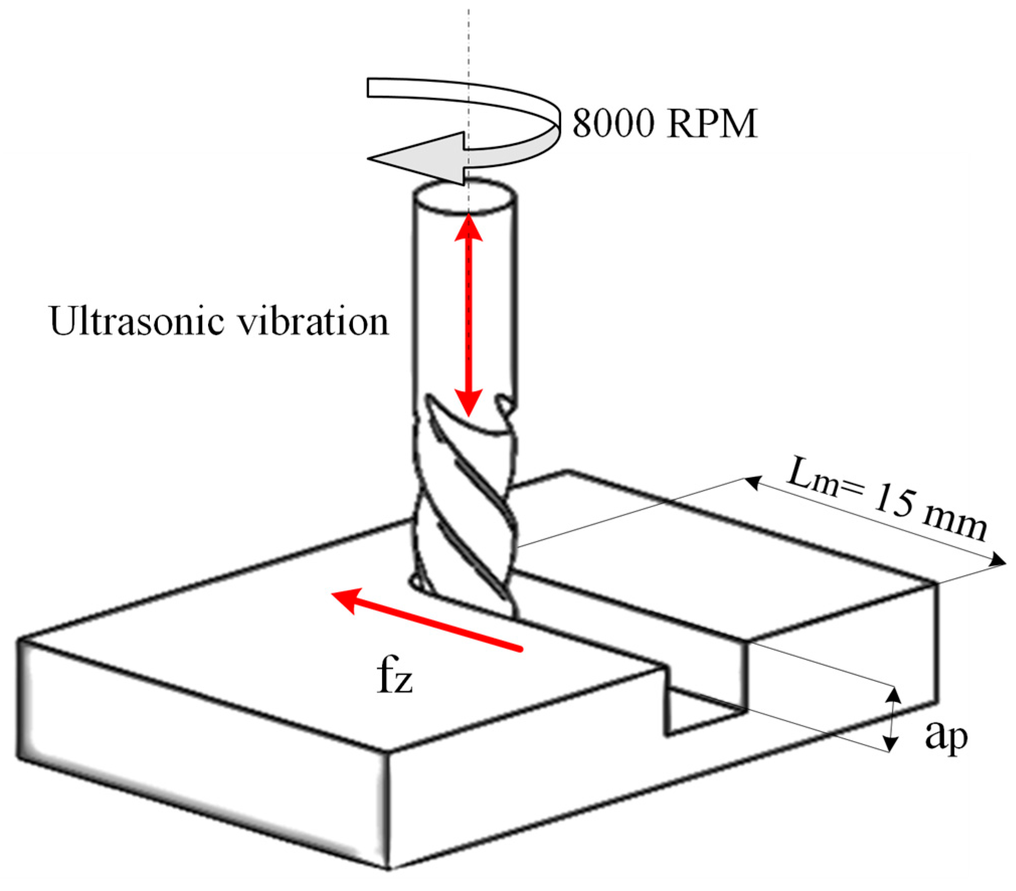
AlCrTiN-coated endmills (Dohler-Tool, Ras Al Khaimah, United Arab Emirates) with a diameter of 1 mm, 4 flutes, and 65 HRC hardness are used in the experiments. Each cutting tool is used to perform a single experiment to eliminate the effect of tool wear. Figure 2 shows the geometrical details of the endmills and the cutting-edge radius measurements using a digital microscope (Keyence VHX-1000, Keyence Corporation, Osaka, Japan). The average value of 5 measurements of the cutting-edge radius (re) for five different tools was found to be 4.215 µm. The ultrasonic-assisted machine tool (DMG MORI ULTRASONIC 20 Linear, DMG Mori, Tokyo, Japan) was used to micro-machine linear slots. Figure 3 shows the process diagram, where the cutting speed is kept at 8000 rpm, which is the maximum spindle speed available on the machine when using ultrasonic mode while machining length for the slot is 15 mm. The ultrasonic frequency is selected to be the resonance frequency of the cutting tool, which is between 23.5 and 24 kHz with a corresponding displacement amplitude of 1.5 to 2 µm.
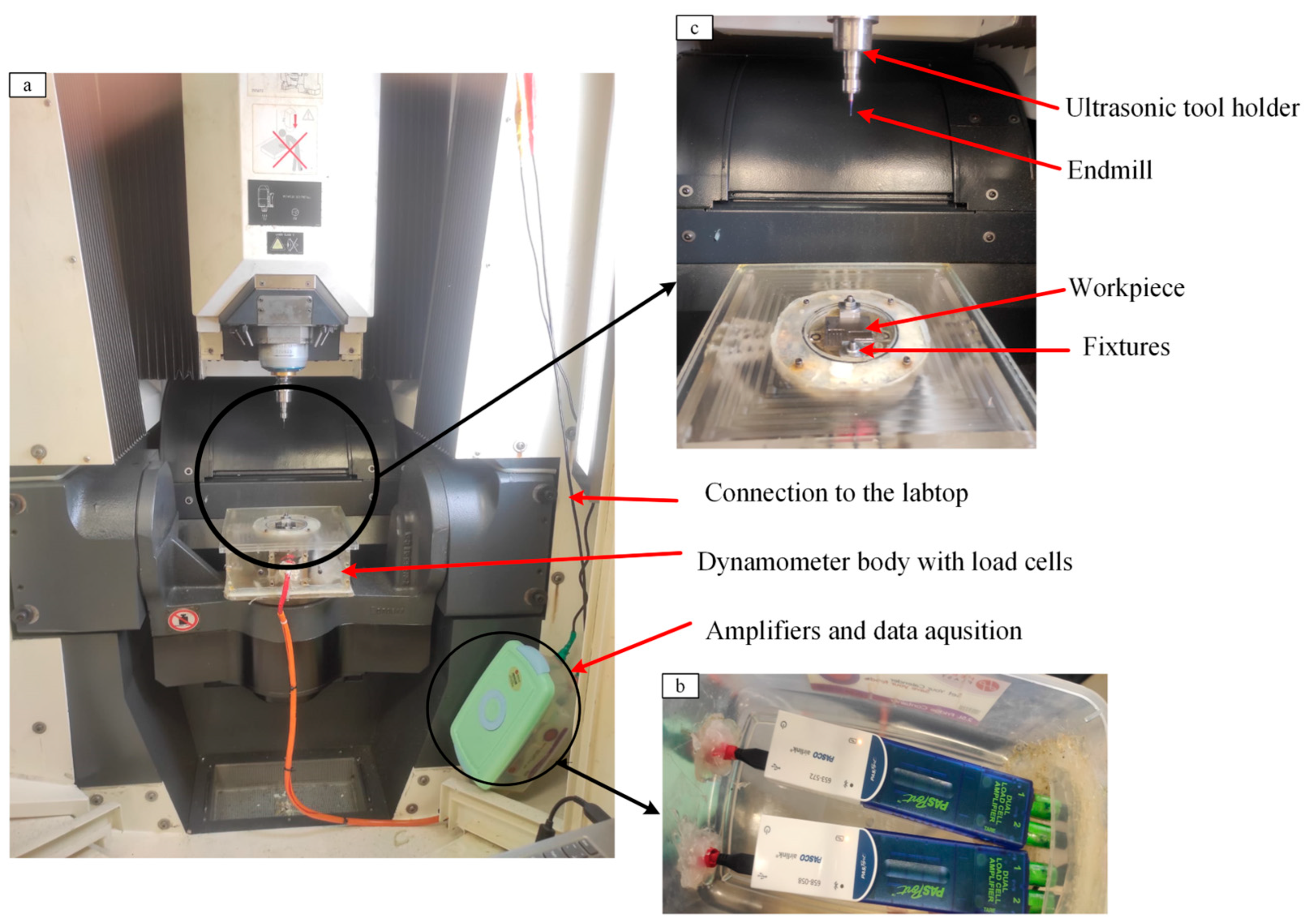
The machining setup is depicted in Figure 4, which illustrates the workpiece fixation and the dynamometer with three load cells. These load cells are linked to PASCO amplifiers and data-acquisition systems, (Figure 4b) to capture the force signals. This cutting-force measurement configuration is designed and calibrated in previous work by Monir et al. [46]. Figure 4c presents the workpiece fixed to the surface of the dynamometer, with the cutting tool secured in the ultrasonic tool holder.
The experimental design is planned using Minitab 19 software to study the effect of feed-per-tooth (fz) and axial depth-of-cut (ap), as they are the most important factors controlling the micro-milling mechanism. Three levels are selected for each parameter (feed-per-tooth, and axial depth-of-cut), in addition to the presence of ultrasonic vibration as the third factor. Full factorial design is selected, resulting in a total number of 18 experimental conditions, as illustrated in Table 3. To reduce the experimental errors, the experiments were performed with two replications, resulting in a total of 36 experiments. Cutting forces are measured in the x, y, and z directions during micro-machining, using the dynamometer illustrated in Figure 4. The maximum force in the steady-state region is recorded in each direction, then the resultant force value is calculated and taken as an input for analysis. Figure 5 shows an example of the measured cutting-force signals.
For a thorough explanation of the cutting-force results, images for the cutting-tool edges after machining are captured using Tool Maker microscope (Mitutoyo MF-A2010D Series 176, Mitutoyo Corporation, Kawasaki, Japan).
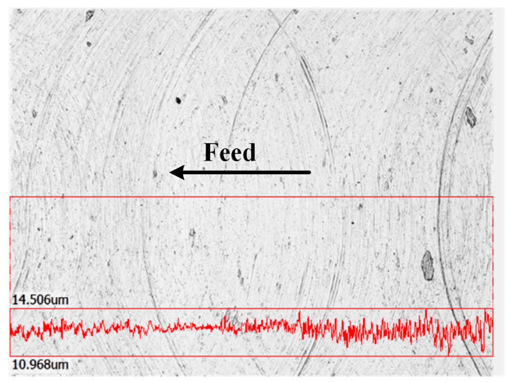
Surface roughness and burr formation are assessed utilizing the 3D laser microscope (KeyenceVK-X100, Keyence Corporation, Osaka, Japan). To evaluate surface roughness, three images are captured along the entire length of the slot at a magnification of 20×. The VK analyzer software is employed to compute the arithmetic average roughness (Ra) for three lines in the feed direction for each image, yielding a total of nine Ra measurements for each experimental run. The average of these measurements is calculated for further analysis using Minitab 19. Figure 6 illustrates the measurement methodology and orientation.
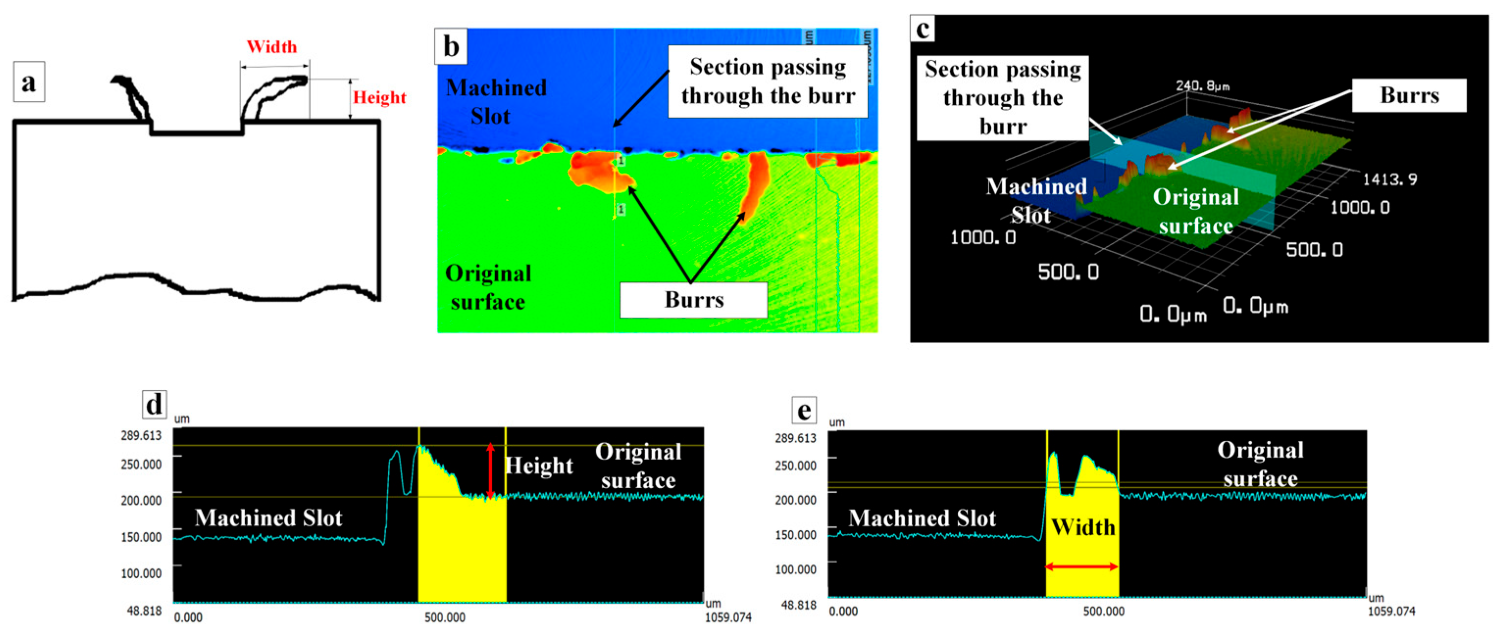
Regarding burrs, the top burrs are analyzed by separately measuring the height and width of the burrs on both the up-milling and down-milling sides. Two images are taken for each side, at a magnification of 10×, and three burr positions are selected for each image, with their heights and widths recorded using the software, resulting in a total of six measurements for each parameter. The average value is similarly computed for analysis. Another set of images are taken using the upright optical microscope (OLYMPUS 1000, Olympus Corporation, Tokyo, Japan) with 5× magnification to facilitate a comparison of the overall burr profiles under each condition. Figure 7 depicts the burr measurement techniques and methodologies for one of the measurements. Figure 7a shows an illustration of the burr width and height. After taking the image using laser microscope, a section plane was taken, passing through the burr profile, and illustrated in Figure 7b,c. From the profile of the section plane, the height was measured as the difference between the burr and the original surface, and the width was taken by measuring the horizontal distance of the burr and depicted in Figure 7d and Figure 7e, respectively.

3. Results and Discussion

Table 4 and Table 5 present a summary of the ANOVA results for the investigated micro-milling parameters, including the feed-per-tooth, the axial depth-of-cut, the ultrasonic-assisted vibrations, and their interactions. The results are characterized by the p-value, where a value of 0.05 or lower indicates that the parameter is significant, as shown in Table 4. Table 5 shows the percentage contribution of each factor and factors interactions on the evaluated performance measures.

3.1. Cutting Forces

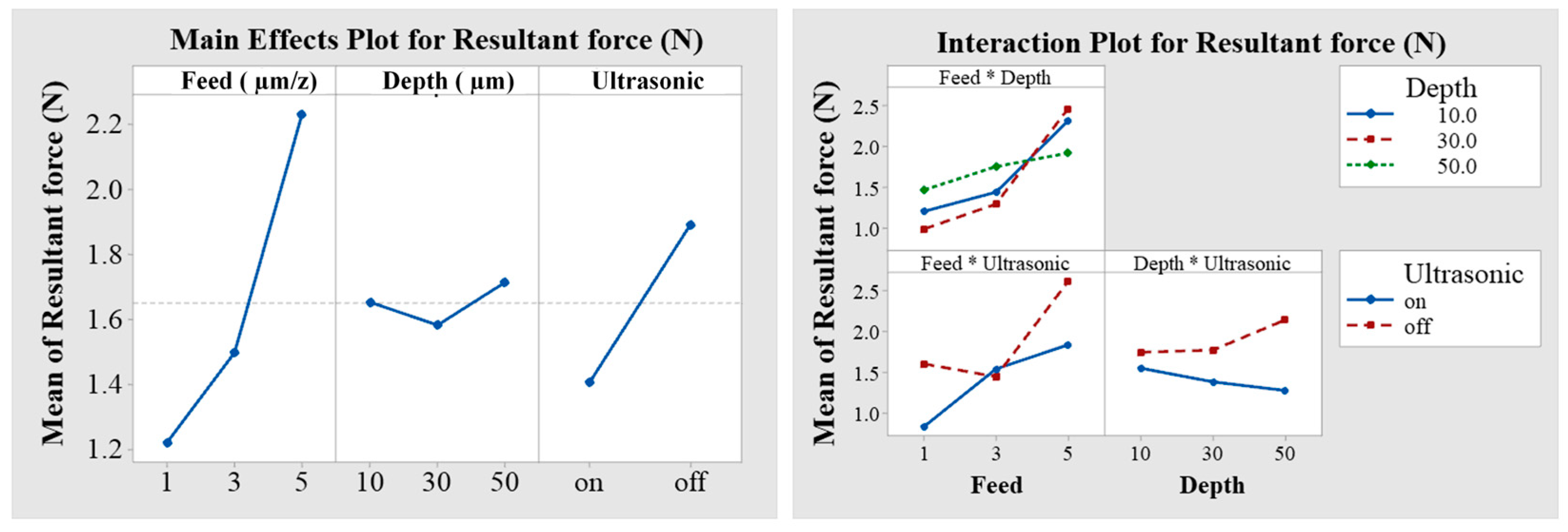
Figure 8 shows the main effect plot for the resultant force. The resultant force exhibited a significant increase as fz was raised, with p-value = 0.000 and the highest percentage contribution of 29.29%, as seen in Table 4 and Table 5. It is also observed from the interaction plot that in the absence of ultrasonic vibrations, the force initially slightly decreased before subsequently increasing. Conversely, with the application of ultrasonic vibrations, the force consistently increased alongside the fz as shown in Figure 8. The depth-of-cut was also found to be significant, showing a similar behaviour to the feed-per-tooth with p-value = 0.007 and the second-highest contribution of 15.20%. It is further noted from the interaction plots that, with ultrasonic vibrations, the cutting force decreases with the increase in depth-of-cut, which is the reverse of when conventional machining is applied. This behaviour could be due to the increased softening effect of ultrasonic vibrations when the tool is engaged in higher depths, which leads to further reduction in the cutting forces. Notably, ultrasonic vibrations led to a substantial reduction in cutting force on average, by 20% with p-value = 0.021, which is due to the periodic separation that enhances heat evacuation, reduces the friction between the cutting tool and the workpiece, and reduces the chip size by breaking it, all of which leads to reduced cutting forces.
Figure 9 shows the cutting-force results in different cutting conditions. For each experiment, the height of the bar is the average of the two replications, while the error bars are the standard errors for each condition, which was calculated as stated in Equation (1):
S E = σ n
where σ is the standard deviation and n are the number of samples.
The maximum cutting force was 1.884 N during conventional micro-milling at ap = 50 µm and fz = 3 µm/z, followed by 1.803 N at ap = 30 µm and fz = 5 µm/z, which can be linked to the increased undeformed chip area. Moreover, the resultant force almost increased as ap or fz was raised from the minimum to the maximum values, both with and without ultrasonic vibrations, as shown in Figure 9, which confirm the factorial plot results shown in Figure 8. Figure 9 further highlighted the role of ultrasonic assistance in reducing force, showing that in all tested conditions, the cutting force is less when ultrasonic is on compared to when it is off.
Under the present axial ultrasonic-assisted micro-milling conditions (amplitude = 1.5–2.0 µm; frequency = 24 kHz), the peak vibration velocity is approximately 0.23–0.30 m/s. Given the cutting speed of 25 m/min (≈0.42 m/s), the vibration velocity is of the same order of magnitude—about 55–70% of the cutting speed—indicating that the tool periodically separates from the workpiece during each vibration cycle. The corresponding peak acceleration ranges from approximately 3.4 × 10⁴ m/s2 to 4.5 × 10⁴ m/s2, reflecting the high instantaneous dynamic loads acting within the cutting zone. Such intermittent tool–workpiece contact is known to reduce the average cutting forces and temperature by modulating the contact stress [47]. In addition to the kinematic effects, ultrasonic excitation induces oscillatory stresses within the cutting zone, leading to cyclic stress superposition and local variations in strain rate. These oscillations can trigger acoustic or acousto-plastic softening, reduce the flow stress of the work material and further contribute to the observed force reduction and improved surface finish [48]. Overall, both the intermittent tool–workpiece interaction and stress-modulated softening phenomena are governed by the vibration velocity amplitude and frequency, which define the dynamic energy input during ultrasonic-assisted milling.
In addition, according to Ibrahim et al. [49] the application of 2D ultrasonic vibration-assisted micro-milling reduces cutting temperature by 40–50% and decreases tool wear by approximately 60% due to its intermittent cutting mechanism, which creates micro-gaps for heat dissipation which contributed cutting forces reduction by 40–50%. Another study by Feng et al. [50] found that ultrasonic vibration-assisted milling significantly reduces cutting temperatures through periodic tool–workpiece separation, preventing thermal accumulation. Experimental validation showed that increasing vibration amplitude from 9 μm to 20 μm reduced the cutting temperature from 45.8 °C to 41.5 °C due to the increase in the separation period.
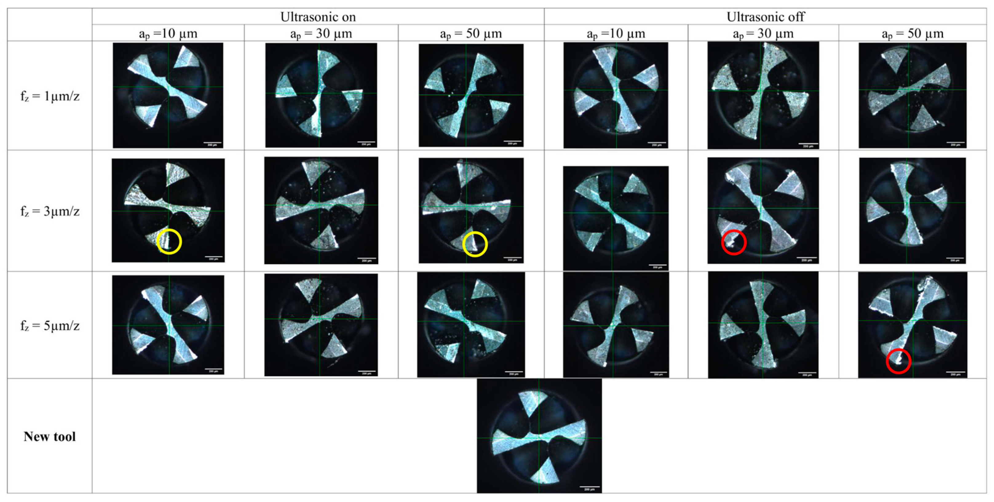
Cutting forces are closely associated with tool wear; as cutting forces increase, the resulting rise in friction and cutting temperature accelerates the degradation of coating layers and promotes the formation of built-up edges (BUEs). Figure 10 presents images of the endmills after machining under various experimental conditions, captured using a toolmaker’s microscope. Two primary wear mechanisms were observed: adhesive wear, which leads to BUE formation and is highlighted by a red circle in two of the samples, as shown in Figure 10, and abrasive wear, characterized by gradual coating degradation and marked by a yellow circle in another samples. It is evident from Figure 10 that the application of ultrasonic vibration leads to a reduction in BUE, which corresponds with the factorial plots and the data presented in Figure 8 and Figure 9. This reduction in BUE can be attributed to the significant decrease in cutting force caused by lower temperatures and improved heat dissipation, which in turn mitigates BUE formation, as BUEs are typically generated by elevated temperatures. Importantly, the condition of the tools is superior even under the most extreme parameters of fz = 5 µm/z and ap = 50 µm compared to what is achieved in traditional micromachining. Concerning the influence of fz and ap, both coating removal and BUE were predominantly noted at values ranging from fz = 3–5 µm/z and ap = 30–50 µm during conventional micro-milling, which aligns with the increased cutting-force values observed under the same conditions in Figure 9. Nevertheless, this trend is less pronounced when ultrasonic vibration is utilized due to the diminished cutting forces. Additionally, it is noteworthy that the tool condition improves with an increase in ap to 50 µm in comparison to 10 µm when ultrasonic vibration is applied, which is consistent with the findings of the interaction plot in Figure 8.
The effect of the ultrasonic vibrations on reducing tool wear was consistent with the research conducted by Kuan-Ming Li et al. [42], who investigated ultrasonic-assisted micro-milling of H13 steel and discovered that the introduction of axial ultrasonic vibration diminished tool wear and improved surface quality. The limited tool life is regarded as one of the drawbacks of micro-milling, particularly since Ti6AL4V is prone to BUE formation. The use of axial ultrasonic vibration facilitates periodic separation, enhancing chip evacuation and heat dissipation, thereby reducing cutting forces and BUE formation [51]. It was also noted by Mahmat et al. [43] that employing ultrasonic vibrations in a vertical orientation during the machining of Ti6Al4V leads to a reduction in cutting forces. This reduction occurs because ultrasonic vibrations facilitate thermal softening, thereby decreasing the material’s resistance to removal. Furthermore, ultrasonic vibrations reduce the friction by creating periodic separations between the tool and the workpiece. In addition, existing literature shows that intermittent contact and reduced heat flux contribute to reduced adhesion/BUE formation [52].
In full-slot milling of Ti–6Al–4V with a four-flute micro end mill, the flutes’ limited chip-removal spaces restrict chip evacuation, promoting chip congestion and secondary cutting that accelerate tool wear and increase cutting forces. In this study, ultrasonic assistance significantly reduced both forces and wear. This improvement is mainly due to the intermittent cutting and chip-segmentation effects of ultrasonic vibration, which promote chip breaking and reduce continuous contact between the tool and workpiece. While tool geometry governs chip-removal capacity, ultrasonic vibration modifies chip-formation dynamics. Similar trends have been reported in ultrasonic-assisted machining of Ti alloys, where intermittent contact and chip fragmentation lower forces and extend tool life [53,54].
The application of ultrasonic vibrations enables the achievement of lower cutting forces, even at increased depth and feed-per-tooth. As illustrated in both Figure 8 and Figure 9, ultrasonic cutting forces remain significantly low, which permits an increase in feed and depth, which is an aspect that can positively influence burr formation and surface texture, as will be discussed in the subsequent sections.

3.2. Burr Formation

3.2.1. Burrs Types and Chip Formation

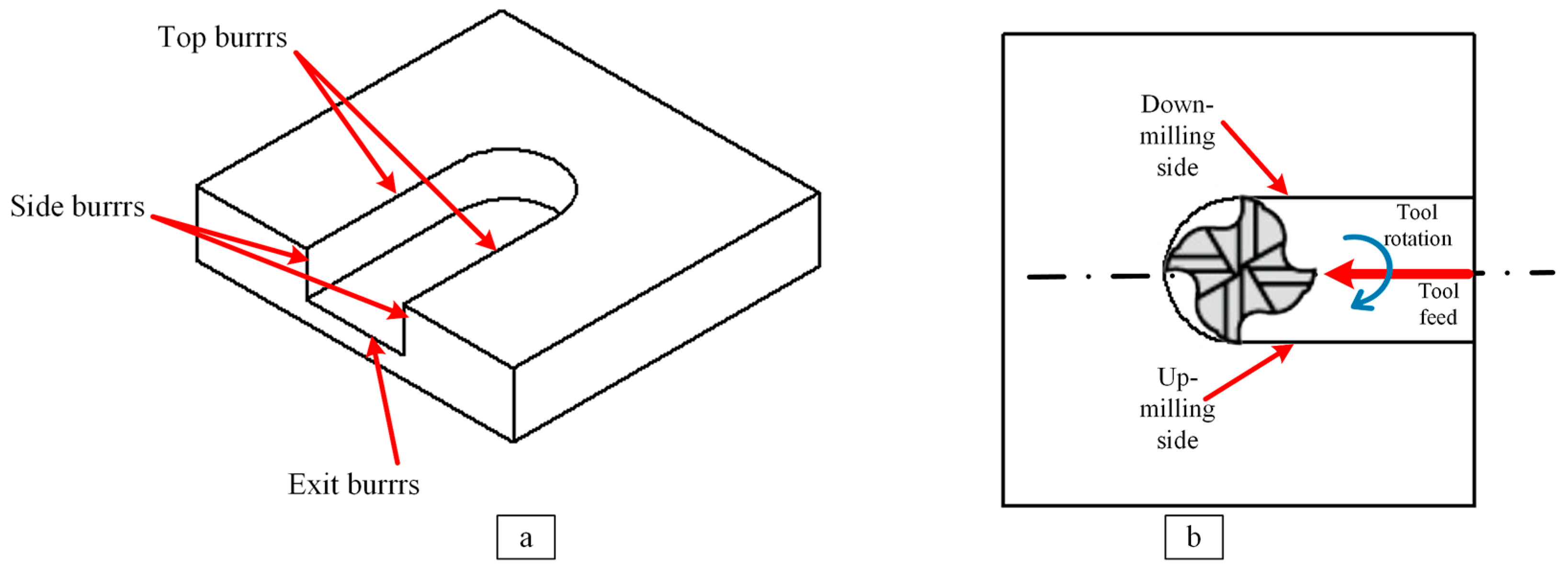
Milling burrs can be categorized based on their location into top burrs, side burrs, and exit burrs [55], as illustrated in Figure 11a. Top burrs pose a significant challenge in micro-milling due to their size being large when compared to the micro-slot size, making them unavoidable and difficult to remove. Top burrs can be classified into up-milling-side and down-milling-side burrs depending on their location relative to the cutting-tool rotation and feed directions, as shown in Figure 11b.
The initial formation of burrs occurs on the up-milling side due to the extrusion effect and ploughing, as the feed-per-tooth is insufficient to facilitate effective chip formation by shearing. This leads to an increase in ploughing because the uncut chip thickness (UCT) is minimal, causing it to be compressed beneath the cutting edge. This thickness gradually increases, transitioning the cutting process from ploughing to shearing at the minimum undeformed chip thickness hmin until the middle of the slot; then subsequently decreasing again near the down-milling side and the mechanism shifts back to ploughing, resulting in tearing chips that create down-milling-side burrs. The size of the ploughing regions in the up- and down-milling edges is responsible for burr formation [40].
Figure 12 delineates the fundamental distinctions between macro- and micro-scale cutting operations. In the macro-scale regime (Figure 12a), the uncut chip thickness (UCT) is substantially greater than the minimum undeformed chip thickness (hmin). Under these conditions, the material removal mechanism is dominated by shearing, facilitated by the tool’s specified rake angle (γ). This results in the formation of well-defined chips and a confined ploughing zone only near the slot edges, consequently yielding negligible burr formation. Burrs, which result from uncontrolled plastic deformation rather than clean shear, are thus minimized. Conversely, in micro-scale cutting (Figure 12b), the feed-per-tooth is comparable to hmin. This geometric scaling leads to the prevalence of ploughing and extrusion over shearing as the primary material removal mechanism. The low UCT induces a pronounced negative effective rake angle (γeff), rather than the tool nominal rake angle (γ), preventing clean chip formation initially. Although a transition to a shearing-dominated mechanism may occur as the chip thickness increases within the cut, the ploughing phase remains predominant throughout the cycle. This sustained plastic deformation results in the generation of burrs that are considerably large relative to the micro-scale slot dimensions. The minimum undeformed chip thickness (hmin) is predominantly affected by the cutting-edge radius (re), along with other variables such as the material of the workpiece and its grain size. It is mostly defined by researchers as the condition where the width of the top burr is at its minimum.

3.2.2. Parameters Affecting Burr Size

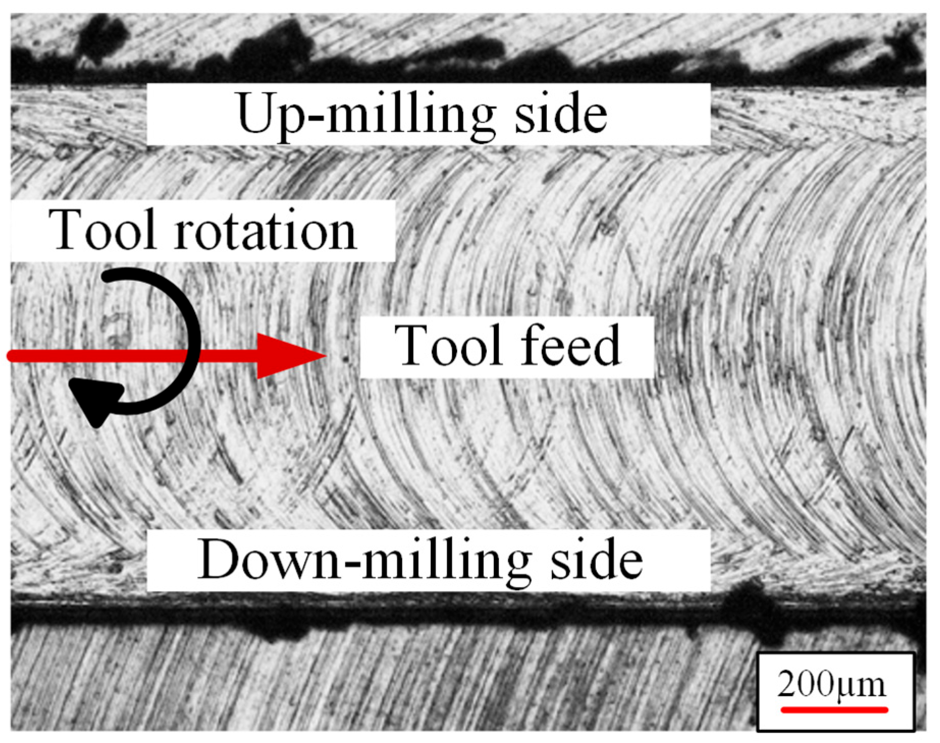
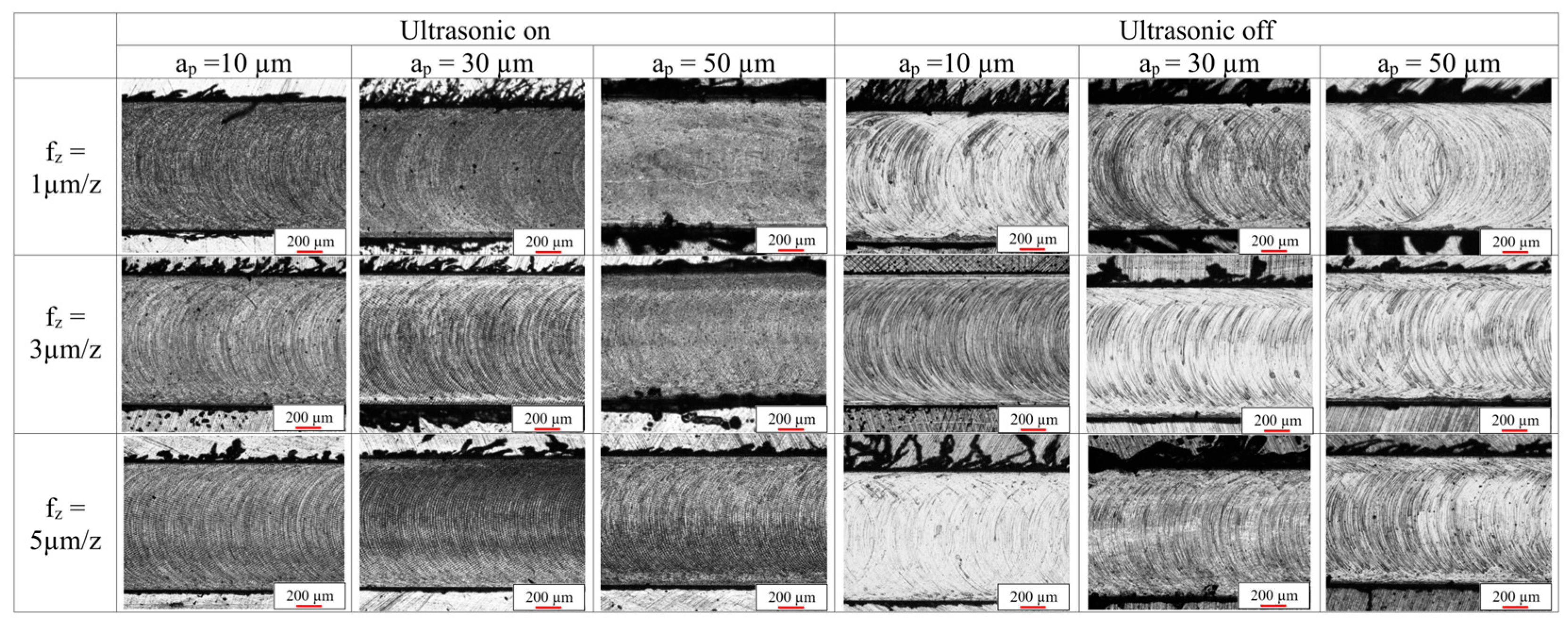
Burr formation is assessed by measuring two parameters: height and width, as indicated previously in Figure 7. The values were obtained using a laser microscope; however, optical microscope images were utilized to provide a comprehensive view of the burr shapes and the machined surface. Figure 13 shows the locations of up- and down-milling sides and Figure 14 illustrates the microscope images under the different machining conditions. The milling burrs on the up side are significantly larger than those on the down-milling side, as shown in Figure 13, which is consistent with the findings of Chen et al. [56]. Leaf- shaped burrs are the most dominant, which occur due to intense extrusion and ploughing actions, generating characteristic flat, ribbon-like chip segments that fail to cleanly separate from the workpiece [57]. The process of burr formation is closely associated with the material removal mechanism, which supports the explanations in the previous section, as the low fz value, which is comparable to the cutting-edge radius, makes the dominant mechanism ploughing rather than shearing.
Figure 15 and Figure 16 present the factorial plots and bar charts for burr width formed in the up- and down-milling sides. It was observed that ultrasonic assistance reduced the width of up-milling-side burrs while increasing the width of down-milling-side burrs, although these changes were not significant. Concerning the depth-of-cut, the width of up-milling side burrs increased consistently with greater depth-of-cut, while the width of down-burrs initially increased with depth and then decreased again at ap = 50 µm, with a significant effect indicated by a p-value of 0.022 and a percentage contribution of 18.33%.
For the feed-per-tooth, the width of burrs on both up- and down-milling sides initially decreased with increasing fz to 3 µm/z by 18.5% and 30.27%, respectively. Although this effect was statistically insignificant, the percentage reduction is considerable. As fz increases to 5 µm/z, both up- and down-milling sides burrs increase slightly. This can be explained by the mechanism of micro-milling; at first, when the feed is minimum, the ploughing phenomenon is dominated resulting into high burr formation, until fz value exceeds hmin—3 µm/z in the current case, the cutting mechanism transforms to normal shearing. After this threshold value, the burr size back to increase again with the increase of fz due to the increase in chip area despite the reduced ploughing.
As depicted in Figure 14 and the bar chart (Figure 16), down-milling-side burrs are generally smaller than those on the up-milling side. The interaction between fz in the down milling-side burr width and ultrasonic vibrations was significant, indicating that the application of ultrasonic vibrations led to a reduction in burr width as the feed-per-tooth increased as evidenced in the interaction plot, where the minimum burr width was observed at fz = 5 µm/z. These results align with the recommendations of Zhang et al. [58], who suggested that increasing the feed-per-tooth can minimize both top- and side-burr widths, and de Oliveira et al. [59], who noted that lower fz values heighten the significance of size effects, which dominate chip formation through elastic–plastic deformation rather than normal shearing.
Burr width was found in research papers to be the most important parameter to specify hmin. According to de Oliveira et al. [6], hmin varies from 1/4 to 1/3 re. Conversely, Wu et al. [57] discovered that the burr width diminishes when fz approaches the re. In this study, the smallest burr width recorded was 3 µm/z, approximately 71% of the cutting-edge radius, which equala 4.215 µm, indicating that hmin is reached when fz approaches re. Although the ultrasonic addition in the axial direction does not directly affect UCT, ultrasonic vibration has been shown to increased hmin, as evidenced by the interaction plots and the optical microscope images in Figure 14 and Figure 15. It has been demonstrated that the smallest burrs are produced at the highest feed rate, which is also clear in the bar charts in Figure 16; when ultrasonic vibration is used at fz = 5 µm/z, the burr widths are smaller than those without ultrasonic assistance.
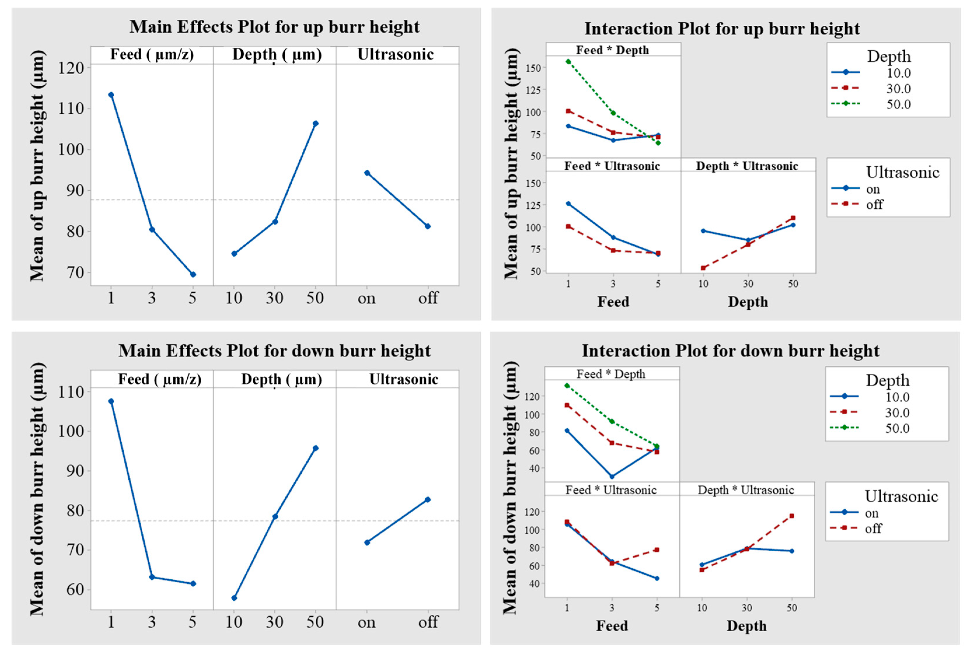
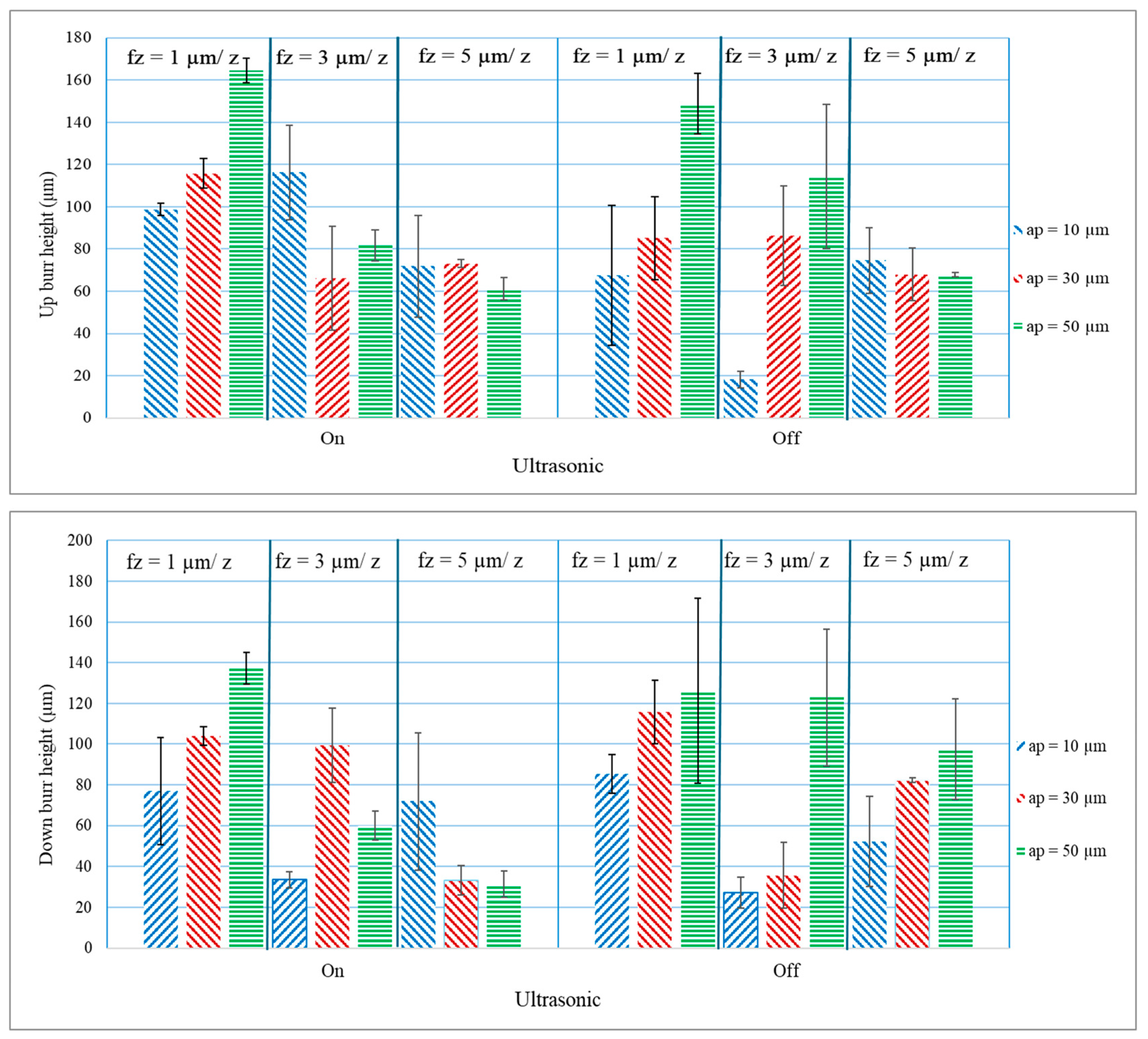
Although burr height was rarely studied as a parameter, it is important to consider it, as the position of the burrs is very high compared to slot depth; this is particularly clear in Figure 17 and Figure 18, which represent the factorial plots and bar charts for burr height formed in the up- and down-milling sides. Similarly to burr width, ultrasonic assistance reduced the height of the up-milling-side burrs while increasing the height of down-milling-side burrs; these changes have a higher percentage effect when compared to burr width. Concerning the depth-of-cut, the height both of up- and down-milling-side burrs increased consistently with greater depth-of-cut. In terms of feed-per-tooth, this is a significant factor influencing burr height, with p-values = 0.019 and 0.018 for the up- and down-milling side, respectively, and percentage contributions of 20.09 and 22.19% can be seen in Table 4 and Table 5, as increasing fz led to a reduction in burr size. It is also noted from the interaction plots in Figure 17 that without ultrasonic assistance, the minimum burr height can be achieved at fz = 3 µm/z; however, when ultrasonic vibrations are used, the fz = 5 µm/z resulted in the minimum burr height, which is consistent with the results of burr width. This is also clear in the bar charts in Figure 16 and Figure 18, indicating that with ultrasonic vibrations at fz = 5 µm/z, the burr height and width are clearly smaller than those without ultrasonic assistance. Although ultrasonic vibrations are in the axial direction and have no direct effect on the UCT in the direction of feed, it seems to delay hmin, so it is advisable to increase the fz beyond re to achieve the lowest possible burr size when ultrasonic vibrations are used.

3.3. Surface Texture

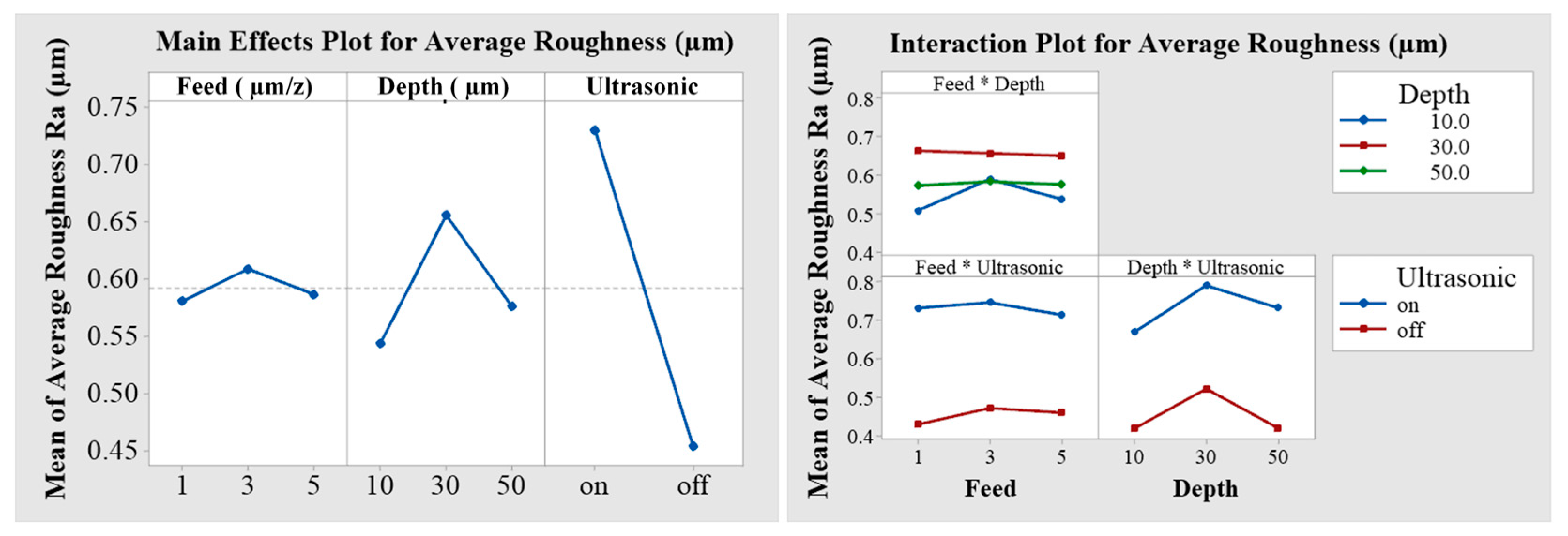
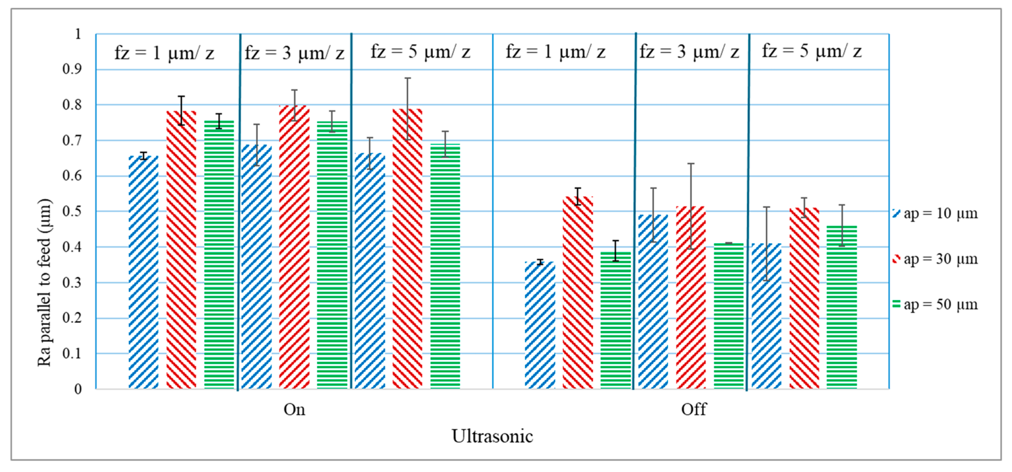
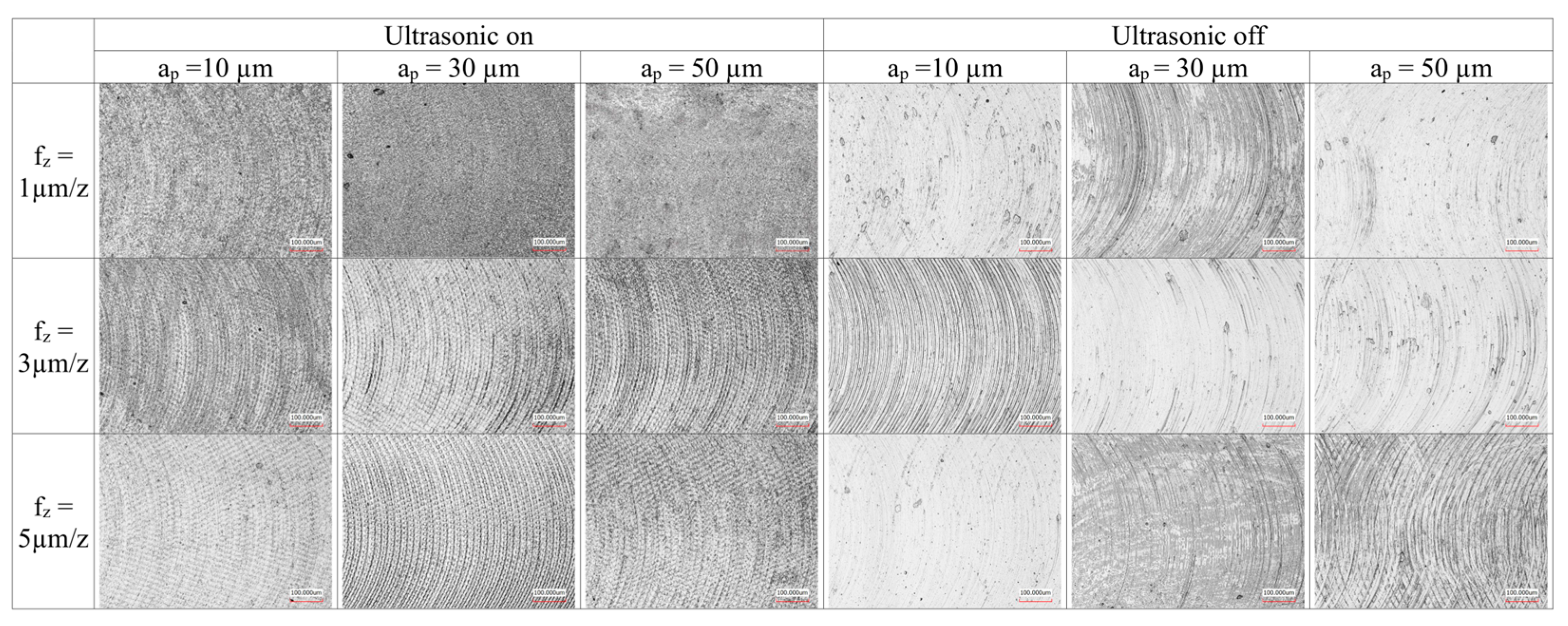
As illustrated in the main effect plot and the bar chart of the results in Figure 19 and Figure 20, and Table 4, there was a significant increase in the arithmetic average surface roughness value Ra when ultrasonic vibrations were employed (p-value = 0.000). The influences of depth-of-cut and feed-per-tooth are comparable; as either parameter increases, the average roughness rises and subsequently decreases. Nevertheless, the impact of depth-of-cut is more pronounced and approaches significance with a p-value of 0.064. The lowest surface roughness was recorded at ap = 10 µm and fz = 1 µm/z without the application of ultrasonic vibrations. An examination of the surface texture in Figure 21 reveals that the increase in roughness is attributed to the uniform fish-scale texture produced by the endmill during the milling process. In contrast to the conventional milling marks or scratches, the wavy dimples resulting from ultrasonic oscillation can improve the tribological characteristics of the machined surface. This is consistent with the research conducted by Kan Zheng et al. [60], who investigated the ultrasonic-assisted milling of TC4 alloy. They discovered that the ultrasonic texture increased the arithmetic average deviation (Sa) in comparison to conventional texture, attributed to the uniformly created dimples. Furthermore, they examined the wear and friction characteristics of the machined surface, revealing that the ultrasonically machined surface decreased the average friction coefficient by as much as 35% and reduced wear volume by up to 67%, owing to hydrodynamic effects from micro-pits that retain lubricant and debris. The early work of Shen and Zhan [61] indicated comparable findings; they discovered that the texture produced through ultrasonic-assisted machining enhanced the surface’s load-bearing capacity by 250% in contrast to that achieved through conventional machining, owing to the presence of dense micro-textures that function as reservoirs for lubricants. It is observed from Figure 22 that the machining marks from conventional milling are irregular, exhibiting non-uniform scratches and surface imperfections such as ploughing regions or adhered material, possibly due to the formation of built-up edges (BUEs), which only vanish at the highest fz of 5 µm/z, ap of 50 µm, and at fz = 3 µm/z, ap = 10 µm; this condition shows the lowest burr widths as illustrated in Figure 16. In the case of ultrasonic vibrations, some surface defects are also present, particularly at low fz and ap, due to the increased ploughing under these conditions. Xia et al. [62] discovered that during the longitudinal–torsional ultrasonic-assisted milling (LTUAM) of Ti2AlNb, the resulting machined surface exhibited greater uniformity and fewer surface defects, thereby enhancing wear resistance.
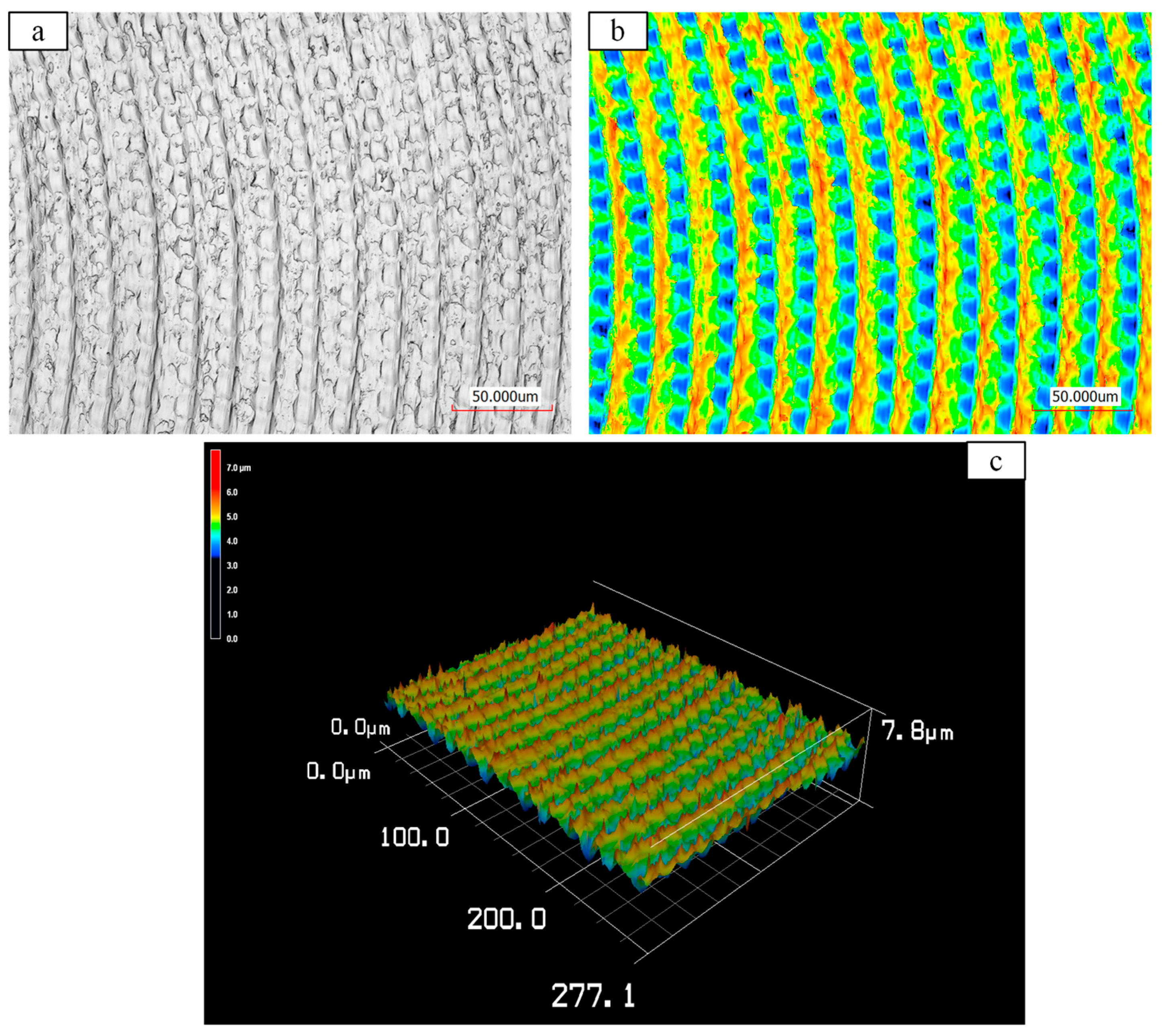
As illustrated in Figure 23, which presents the texture at a higher magnification at fz = 5 µm/z and ap = 30 µm, is composed of uniform micro-dimples with an average width and depth of 0.846 and 7.704 µm, respectively. The characteristics of these dimples, including depth, spacing, and width, can be regulated by the machining and vibration parameters to identify the most appropriate texture for specific applications. Ermiş et al. [63] summarized that micro-pits with widths between 2 and 10 µm and depths around 0.5–2.5 µm enhance cell adhesion and wettability compared with smooth surfaces, due to their moderate hydrophilicity and effective fluid trapping. The dimple geometry observed in this work (7.704 µm × 0.846 µm) falls within this optimum range, suggesting a similar improvement in fluid retention and potential tribological or biointegration performance.
These dimples exhibit a superior capacity to absorb fluids compared to traditionally machined surfaces, which is advantageous for minimizing friction and enhancing the durability of the machined components. Chen et al. [64] investigated the influence of vibration current, cutting speed, and feed on the torsional fretting wear behaviour of ultrasonically assisted milled CuAlNi alloy. They initially determined that UVAM produces uniformly distributed micro-dimples on CuAlNi surfaces, which enhances lubricant retention and wear-debris capture, resulting in a 29.1% reduction in friction torque. Furthermore, they found that increasing the feed, speed, or ultrasonic current contributes to a decrease in friction torque, thereby emphasizing the advantages of the generated texture.
Moreover, D. Xing et al. [65] found that applying ultrasonic vibration in the feed direction creates regular textures on the machined surface. These textures significantly improve tribological performance by enhancing oil film adsorption, providing oil storage, and trapping wear particles. Compared to traditional milling, UVAM surfaces exhibit a 20% reduction in friction coefficient and a 140% increase in oil film-bearing capacity, leading to superior friction stability. In a study by Lotfi et al. [66], 3D elliptical ultrasonic-assisted turning was applied to Ti-6Al-4V to investigate its effect on surface texture and wettability. The process produced semi-spherical micro-dimples and eliminated conventional feed marks, resulting in a reduction in water contact angle compared with conventional turning. The modified surfaces exhibited higher and more isotropic wettability, which highlights the improvement in the wettability of the surfaces produced by ultrasonic-assisted machining.

4. Conclusions

This study examined the influence of ultrasonic vibration assistance along with machining parameters on micro-milling Ti6Al4V, analyzing cutting forces, surface quality, and burr formation applying ANOVA.
  • The results demonstrated that ultrasonic vibration reduced cutting forces significantly by 20.09% through intermittent cutting effects and decreased tool wear by improving chip evacuation. However, it increased surface roughness due to the formation of micro-dimples, which could benefit tribological applications. The ultrasonic vibrations have no significant effect on burr formation; however, it slightly increased the value of the minimum undeformed chip thickness (hmin).
  • The increase in feed-per-tooth significantly increased the cutting forces and BUE formation due to the increase in the chip area. However, the role of fz in controlling burr formation was clear; the results suggest that hmin is reached when fz approaches to re, which was approximately 71% re in the current study.
  • Regarding the increase in the axial depth-of-cut, the cutting forces are significantly increased and is an effective factor in increasing burr formation. For the surface roughness, Ra increased first with the increase of ap and then decreased. This study recommends the use of ap = 10 µm.
For potential industrial adoption, the scalability of ultrasonic micro-milling hinges on addressing cost, tool life, and process stability. While the initial investment in ultrasonic spindle technology remains a barrier, the demonstrated improvements in tool life and reduced cutting forces directly lower operational costs and improve process reliability for hard-to-machine materials like Ti6Al4V. This makes it a compelling candidate for high-value production lines in the aerospace (e.g., micro-features on turbine blades) and biomedical (e.g., custom orthopedic implants) sectors, where precision and material integrity outweigh upfront costs. Future work should focus on integrating this technology with advanced cooling techniques and developing robust, long-life tooling to further enhance machining performance and economic feasibility for serial production.

Author Contributions

Conceptualization, A.W., M.G.A.N., F.P. and I.M.; methodology, A.W., M.G.A.N. and I.M.; software, A.W.; validation, M.G.A.N., F.P. and I.M.; formal analysis, A.W., M.G.A.N., F.P. and I.M.; investigation, A.W., M.G.A.N., F.P. and I.M.; resources, I.M. and F.P.; data curation, A.W.; writing—original draft preparation, A.W.; writing—review and editing, M.G.A.N., F.P. and I.M.; visualization, A.W., M.G.A.N., F.P. and I.M.; supervision, M.G.A.N., F.P. and I.M.; project administration, I.M. All authors have read and agreed to the published version of the manuscript.

Funding

This research received no external funding.

Data Availability Statement

The original contributions presented in this study are included in the article. Further inquiries can be directed to the corresponding authors.

Acknowledgments

The authors gratefully acknowledge Mohamed Monir for providing access to the dynamometer and for his kind support, which contributed significantly to the successful completion of this work.

Conflicts of Interest

The authors declare no conflicts of interest.

Abbreviations

LIGALithography–Electroplating, and Molding
UCTUncut Chip Thickness
FEMFinite-Element Method
DLCDiamond-like Coating
BUEBuilt-up Edge
MQLMinimum Quantity Lubrication
ANOVAAnalysis of Variance
WEDMWire Electrical Discharge Machining
LTUAMLongitudinal Torsional Ultrasonic-assisted Milling
UVAMUltrasonic Vibration-assisted Milling

References

  1. Balázs, B.Z.; Geier, N.; Takács, M.; Davim, J.P. A Review on Micro-Milling: Recent Advances and Future Trends. Int. J. Adv. Manuf. Technol. 2021, 112, 655–684. [Google Scholar] [CrossRef]
  2. Roushan, A.; Rao, U.S.; Sahoo, P.; Patra, K. Performance Study of Uncoated and AlTiN-Coated Tungsten Carbide Tools in Micromilling of Ti6Al4V Using Nano-MQL. J. Braz. Soc. Mech. Sci. Eng. 2023, 45, 63. [Google Scholar] [CrossRef]
  3. Uriarte, L.; Herrero, A.; Zatarain, M.; Santiso, G.; Lopéz de Lacalle, L.N.; Lamikiz, A.; Albizuri, J. Error Budget and Stiffness Chain Assessment in a Micromilling Machine Equipped with Tools Less than 0.3 mm in Diameter. Precis. Eng. 2007, 31, 1–12. [Google Scholar] [CrossRef]
  4. Saha, S.; Sravan Kumar, A.; Deb, S.; Bandyopadhyay, P.P. An Investigation on the Top Burr Formation during Minimum Quantity Lubrication (MQL) Assisted Micromilling of Copper. Mater. Today Proc. 2019, 26, 1809–1814. [Google Scholar] [CrossRef]
  5. O’Toole, L.; Kang, C.W.; Fang, F.Z. Precision Micro-Milling Process: State of the Art. Adv. Manuf. 2021, 9, 173–205. [Google Scholar] [CrossRef] [PubMed]
  6. De Oliveira, F.B.; Rodrigues, A.R.; Coelho, R.T.; De Souza, A.F. Size Effect and Minimum Chip Thickness in Micromilling. Int. J. Mach. Tools Manuf. 2015, 89, 39–54. [Google Scholar] [CrossRef]
  7. Srinivas, M.S.; Sangeeth, P.; Venkaiah, N.; Sankar, M. RState of the Art on Tool Wear Characterization in Micro-Milling. Mater. Today Proc. 2023, 80, 355–363. [Google Scholar] [CrossRef]
  8. Wang, J.; Gong, Y.; Abba, G.; Antoine, J.F.; Shi, J. Chip Formation Analysis in Micromilling Operation. Int. J. Adv. Manuf. Technol. 2009, 45, 430–447. [Google Scholar] [CrossRef]
  9. Li, K.M.; Chou, S.Y. Experimental Evaluation of Minimum Quantity Lubrication in near Micro-Milling. J. Mater. Process Technol. 2010, 210, 2163–2170. [Google Scholar] [CrossRef]
  10. Kumar, M.; Bajpai, V. Investigation of Top Burr Formation in Micromilling for Surface Quality Improvement. J. Mater. Eng. Perform. 2023, 32, 2139–2150. [Google Scholar] [CrossRef]
  11. Silva, L.C.; da Silva, M.B. Investigation of Burr Formation and Tool Wear in Micromilling Operation of Duplex Stainless Steel. Precis. Eng. 2019, 60, 178–188. [Google Scholar] [CrossRef]
  12. Yadav, R.; Chakladar, N.D.; Paul, S. Modelling and Experimental Validation of Burr Control in Micro Milling of Metals. Mater. Today Commun. 2023, 35, 106205. [Google Scholar] [CrossRef]
  13. de Oliveira, D.; Gomes, M.C.; de Oliveira, G.V.; dos Santos, A.G.; da Silva, M.B. Experimental and Computational Contribution to Chip Geometry Evaluation When Micromilling Inconel 718. Wear 2021, 476, 203658. [Google Scholar] [CrossRef]
  14. Kumar, K.; Zindani, D.; Kumari, N.; Davim, J.P. Micro and Nano Machining of Engineering Materials: Recent Developments; Springer: Berlin/Heidelberg, Germany, 2019; ISBN 978-3-319-99899-2. [Google Scholar]
  15. Kiswanto, G.; Mandala, A.; Azmi, M.; Ko, T.J. The Effects of Cutting Parameters to the Surface Roughness in Low Speed Machining of Micro-Milling of Titanium Alloy Ti-6Al-4V. IOP Conf. Ser. Mater. Sci. Eng. 2019, 654, 012013. [Google Scholar] [CrossRef]
  16. Kim, D.H.; Lee, P.; Kim, J.S.; Moon, H.; Lee, S.W. Experimental Study on Micro End-Milling Process of Ti-6AL-4V Using Nanofluid Minimum Quantity Lubrication (MQL). In Volume 1: Materials; Micro and Nano Technologies; Properties, Applications and Systems; Sustainable Manufacturing, Proceedings of the ASME 2014 International Manufacturing Science and Engineering Conference collocated with the JSME 2014 International Conference on Materials and Processing and the 42nd North American Manufacturing Research Conference, Detroit, MI, USA, 9–13 June 2014; American Society of Mechanical Engineers: New York, NY, USA, 2014; pp. 1–7. [Google Scholar]
  17. Lv, B.; Lin, B.; Zhang, J.; Liu, C.; Wang, L.; Sui, T. Micro- and Nano-Scale Spindle Perpendicularity Modulation Method to Enhance the Quality of Milled Surfaces. Int. J. Extrem. Manuf. 2024, 6, 065101. [Google Scholar] [CrossRef]
  18. Ziberov, M.; de Oliveira, D.; da Silva, M.B.; Hung, W.N.P. Wear of TiAlN and DLC Coated Microtools in Micromilling of Ti-6Al-4V Alloy. J. Manuf. Process 2020, 56, 337–349. [Google Scholar] [CrossRef]
  19. Roushan, A.; Srinivas Rao, U.; Patra, K.; Sahoo, P. Multi-Characteristics Optimization in Micro-Milling of Ti6Al4V Alloy. J. Phys. Conf. Ser. 2021, 1950, 012046. [Google Scholar] [CrossRef]
  20. Aslantas, K.; Alatrushi, L.K.H.; Bedir, F.; Kaynak, Y.; Yılmaz, N. An Experimental Analysis of Minimum Chip Thickness in Micro-Milling of Two Different Titanium Alloys. Proc. Inst. Mech. Eng. Part B J. Eng. Manuf. 2020, 234, 1486–1498. [Google Scholar] [CrossRef]
  21. Zhang, Y.; Bai, Q.; Wang, P. 3D Surface Topography Analysis and Functionality-Related Performance of the Machined Surface in Slot Micro-Milling Titanium Alloy Ti6Al4V. Int. J. Adv. Manuf. Technol. 2023, 127, 1609–1629. [Google Scholar] [CrossRef]
  22. Wu, Y.; Chen, N.; Bian, R.; He, N.; Li, Z.; Li, L. Investigations on Burr Formation Mechanisms in Micro Milling of High-Aspect-Ratio Titanium Alloy Ti-6al-4 v Structures. Int. J. Mech. Sci. 2020, 185, 105884. [Google Scholar] [CrossRef]
  23. Wang, P.; Bai, Q.; Cheng, K.; Zhao, L.; Ding, H.; Zhang, Y. Machinability Analysis of Micro-Milling Thin-Walled Ti-6Al-4V Micro Parts under Dry, Lubrication, and Chatter Mitigation Conditions. Proc. Inst. Mech. Eng. Part B J. Eng. Manuf. 2023, 238, 335–346. [Google Scholar] [CrossRef]
  24. Hassanpour, H.; Sadeghi, M.H.; Rezaei, H.; Rasti, A. Experimental Study of Cutting Force, Microhardness, Surface Roughness, and Burr Size on Micromilling of Ti6Al4V in Minimum Quantity Lubrication. Mater. Manuf. Process. 2016, 31, 1654–1662. [Google Scholar] [CrossRef]
  25. Zamani, M.; Farahnakian, M.; Elhami, S. Employment of Ultrasonic Assisted Turning in the Fabrication of Microtextures to Improve the Surface Adhesion of the Titanium Implant. Proc. Inst. Mech. Eng. Part B J. Eng. Manuf. 2021, 235, 1983–1991. [Google Scholar] [CrossRef]
  26. Zhu, L.; Ni, C.; Yang, Z.; Liu, C. Investigations of Micro-Textured Surface Generation Mechanism and Tribological Properties in Ultrasonic Vibration-Assisted Milling of Ti–6Al–4V. Precis. Eng. 2019, 57, 229–243. [Google Scholar] [CrossRef]
  27. Pape, F.; Poll, G. Frictional Properties o Freshwater Fish Skin. In Proceedings of the 3rd African Conference in Tribology (ACT 2020), Dakar, Senegal, 13–15 April 2022. [Google Scholar]
  28. Pape, F.; Dong, S.; Poll, G. Fluid-Structure Interaction Coupling for Elastohydrodynamic Lubricated Micro Structured Contacts. In Proceedings of the Eleventh International Conference on Engineering Computational Technology, Mallorca, Spain, 23–25 August 2020; pp. 8–10. [Google Scholar]
  29. Kelley, J.; Poll, G.; Pape, F. Investigation of the Possible Applications for Microtextured Rolling Bearings. Front. Manuf. Technol. 2022, 2, 1012343. [Google Scholar] [CrossRef]
  30. Celaya, A.; De Lacalle, L.N.L.; Campa, F.J.; Lamikiz, A. Ultrasonic Assisted Turning of Mild Steels. Int. J. Mater. Prod. Technol. 2010, 37, 60–70. [Google Scholar] [CrossRef]
  31. Verma, G.C.; Pandey, P.M.; Dixit, U.S. Modeling of Static Machining Force in Axial Ultrasonic-Vibration Assisted Milling Considering Acoustic Softening. Int. J. Mech. Sci. 2018, 136, 1–16. [Google Scholar] [CrossRef]
  32. Yuan, Z.; Fang, B.; Zhang, Y.; Wang, F. Effect of Cutting Parameters on Chips and Burrs Formation with Traditional Micromilling and Ultrasonic Vibration Assisted Micromilling. Int. J. Adv. Manuf. Technol. 2022, 119, 2615–2628. [Google Scholar] [CrossRef]
  33. Yuan, Z.; Fang, B.; Dong, Y.; Ding, H.; Zhang, Y. Study on Surface Texture and Corrosion Resistance of Ultrasonic Vibration-Assisted Micromilling Inconel718. Int. J. Adv. Manuf. Technol. 2022, 121, 601–618. [Google Scholar] [CrossRef]
  34. Fang, B.; Yuan, Z.; Li, D.; Gao, L. Effect of Ultrasonic Vibration on Finished Quality in Ultrasonic Vibration Assisted Micromilling of Inconel718. Chin. J. Aeronaut. 2021, 34, 209–219. [Google Scholar] [CrossRef]
  35. Greco, S.; Klauer, K.; Kirsch, B.; Aurich, J.C. Vibration-Assisted Micro Milling of AISI 316L Produced by Laser-Based Powder Bed Fusion. J. Manuf. Process 2021, 71, 298–305. [Google Scholar] [CrossRef]
  36. Xu, L.H.; Na, H.B.; Han, G.C. Machinablity Improvement with Ultrasonic Vibration–Assisted Micro-Milling. Adv. Mech. Eng. 2018, 10, 1687814018812531. [Google Scholar] [CrossRef]
  37. Lian, H.; Guo, Z.; Huang, Z.; Tang, Y.; Song, J. Experimental Research of Al6061 on Ultrasonic Vibration Assisted Micro-Milling. Procedia CIRP 2013, 6, 561–564. [Google Scholar] [CrossRef]
  38. Feng, X.; Dong, Z.; Li, B.; Peng, H. Finite Element Simulation and Experimental Analysis of Axial Ultrasonic Vibration-Assisted Micro-Milling of 316L Stainless Steel. Int. J. Adv. Manuf. Technol. 2024, 133, 4365–4383. [Google Scholar] [CrossRef]
  39. Ullah, S.; Khan, M.A.; Umeed, M.; Juraev, N.; Ijaz Khan, M. Finite Element Simulation Investigation on Ultrasonic Vibration Assisted Micro Milling of AISI 410 Grade MSS. Int. J. Interact. Des. Manuf. 2024. [Google Scholar] [CrossRef]
  40. Zhang, Y.; Yuan, Z.; Fang, B.; Gao, L.; Chen, Z.; Su, G. Study on the Mechanism of Burr Formation by Simulation and Experiment in Ultrasonic Vibration-Assisted Micromilling. Micromachines 2023, 14, 625. [Google Scholar] [CrossRef]
  41. Satpute, V.; Huo, D.; Hedley, J.; Dale, C. A Comprehensive Experimental Investigation into Vibration-Assisted Micro-Milling of Monocrystalline Silicon. J. Manuf. Process 2024, 131, 12–26. [Google Scholar] [CrossRef]
  42. Li, K.M.; Wang, S.L. Effect of Tool Wear in Ultrasonic Vibration-Assisted Micro-Milling. Proc. Inst. Mech. Eng. Part B J. Eng. Manuf. 2014, 228, 847–855. [Google Scholar] [CrossRef]
  43. Mahmat, A.; Agar, S.; Tosun, N. Ultrasonic-Assisted High-Speed Micro-Milling of Ti6Al4V. J. Braz. Soc. Mech. Sci. Eng. 2025, 47, 46. [Google Scholar] [CrossRef]
  44. Liu, X.F.; Wang, W.H.; Jiang, R.S.; Xiong, Y.F.; Lin, K.Y. Tool Wear Mechanisms in Axial Ultrasonic Vibration Assisted Milling In-Situ TiB2/7050Al Metal Matrix Composites. Adv. Manuf. 2020, 8, 252–264. [Google Scholar] [CrossRef]
  45. Zhang, C.; Zhao, B.; Zhao, C. Effect of Ultrasonic Vibration-Assisted Face Milling on the Surface Microstructure and Tribological Properties. J. Vibroeng. 2022, 24, 1–17. [Google Scholar] [CrossRef]
  46. Mansour, M.M.; Maher, I.; Nassef, M.G.A.; El-Hofy, H.; Yan, J.; Khairaldien, W.M. Statistical Modeling and Optimization of Ultrasonic Vibration Assisted End Grinding of Alumina Ceramics. Int. J. Interact. Des. Manuf. 2025, 19, 7283–7301. [Google Scholar] [CrossRef]
  47. Nath, C.; Rahman, M. Effect of Machining Parameters in Ultrasonic Vibration Cutting. Int. J. Mach. Tools Manuf. 2008, 48, 965–974. [Google Scholar] [CrossRef]
  48. Guo, S.; Du, W.; Jiang, Q.; Dong, Z.; Zhang, B. Surface Integrity of Ultrasonically-Assisted Milled Ti6Al4V Alloy Manufactured by Selective Laser Melting. Chin. J. Mech. Eng. (Engl. Ed.) 2021, 34, 67. [Google Scholar] [CrossRef]
  49. Ibrahim, M.R.; Rahim, Z.; Rahim, E.; Tobi, L.; Cheng, K.; Ding, H. An Experimental Investigation of Cutting Temperature and Tool Wear in 2 Dimensional Ultrasonic Vibrations Assisted Micro-Milling. In Proceedings of the MATEC Web of Conferences, Shanghai, China, 21–23 October 2016; EDP Sciences: Les Ulis, France, 2017; Volume 95. [Google Scholar]
  50. Feng, Y.; Hsu, F.C.; Lu, Y.T.; Lin, Y.F.; Lin, C.T.; Lin, C.F.; Lu, Y.C.; Liang, S.Y. Temperature Prediction of Ultrasonic Vibration-Assisted Milling. Ultrasonics 2020, 108, 106212. [Google Scholar] [CrossRef] [PubMed]
  51. Rauf, A.; Khan, M.A.; Jaffery, S.H.I.; Butt, S.I. Effects of Machining Parameters, Ultrasonic Vibrations and Cooling Conditions on Cutting Forces and Tool Wear in Meso Scale Ultrasonic Vibrations Assisted End-Milling (UVAEM) of Ti–6Al–4V under Dry, Flooded, MQL and Cryogenic Environments—A Statistical Analysis. J. Mater. Res. Technol. 2024, 30, 8287–8303. [Google Scholar] [CrossRef]
  52. Zhao, P.; Lin, B.; Zhou, J.; Lv, B.; Li, J.; Zhang, J.; Wang, L.; Sui, T. Review of Grinding Temperature Theory and Measurement for the Needs of the Times: Promoting the Development of Advanced Manufacturing. J. Mater. Process. Technol. 2025, 337, 118744. [Google Scholar] [CrossRef]
  53. Su, Y.; Li, L. An Investigation of Cutting Performance and Action Mechanism in Ultrasonic Vibration-Assisted Milling of Ti6al4v Using a Pcd Tool. Micromachines 2021, 12, 1319. [Google Scholar] [CrossRef]
  54. Rinck, P.M.; Gueray, A.; Zaeh, M.F. Modeling of Cutting Forces in 1-D and 2-D Ultrasonic Vibration-Assisted Milling of Ti-6Al-4V. Int. J. Adv. Manuf. Technol. 2022, 119, 1807–1819. [Google Scholar] [CrossRef]
  55. Aurich, J.C.; Dornfeld, D.; Arrazola, P.J.; Franke, V.; Leitz, L.; Min, S. Burrs-Analysis, Control and Removal. CIRP Ann. Manuf. Technol. 2009, 58, 519–542. [Google Scholar] [CrossRef]
  56. Chen, Z.; Wu, X.; He, L.; Jiang, F.; Shen, J.; Zhu, L. Comparative Study on Micro-Milling Machinability of Titanium Alloys Prepared by Different Processes: Forging Process, Additive Manufacturing Process and Heat-Treatment Process. Precis. Eng. 2024, 88, 164–176. [Google Scholar] [CrossRef]
  57. Wu, X.; Du, M.; Shen, J.; Jiang, F.; Li, Y.; Liu, L. Experimental Research on the Top Burr Formation in Micro Milling. Int. J. Adv. Manuf. Technol. 2021, 117, 3477–3486. [Google Scholar] [CrossRef]
  58. Yabo, Z.; Qingshun, B.; Yangyang, S.; Donghai, L. Burr Formation Mechanism and Machining Parameter Effect in Slot Micro-Milling Titanium Alloy Ti6Al4V. Int. J. Adv. Manuf. Technol. 2022, 123, 2073–2086. [Google Scholar] [CrossRef]
  59. de Oliveira, D.; Ziberov, M.; de Paiva, R.L.; da Silva, M.B. An Experimental Evaluation of Cutting Parameters Influence on the Surface Integrity and Tool Wear Mechanisms on the Dry Micromilling of Austenitic Alloy Inconel 718. Wear 2025, 571, 205789. [Google Scholar] [CrossRef]
  60. Zheng, K.; Liao, W.; Dong, Q.; Sun, L. Friction and Wear on Titanium Alloy Surface Machined by Ultrasonic Vibration-Assisted Milling. J. Braz. Soc. Mech. Sci. Eng. 2018, 40, 411. [Google Scholar] [CrossRef]
  61. Shen, X.; Zhang, J. Studies on Friction and Wear Properties of Surface Produced by Ultrasonic Vibration-Assisted Milling. Int. J. Adv. Manuf. Technol. 2013, 67, 349–356. [Google Scholar] [CrossRef]
  62. Xia, Z.; Gao, G.; Wang, Y.; Zhang, M.; Jia, F.; Shan, C. Surface Micro-Texture and Tribological Properties in Longitudinal-Torsional Ultrasonic-Assisted Milling Ti2AlNb. Int. J. Adv. Manuf. Technol. 2023, 126, 1919–1935. [Google Scholar] [CrossRef]
  63. Ermis, M.; Antmen, E.; Hasirci, V. Micro and Nanofabrication Methods to Control Cell-Substrate Interactions and Cell Behavior: A Review from the Tissue Engineering Perspective. Bioact. Mater. 2018, 3, 355–369. [Google Scholar] [CrossRef]
  64. Chen, X.; Zhai, W.; Dong, S.; Zheng, K.; Xu, R.; Wang, J.; Liu, X.; Lu, W. Investigations on Torsional Fretting Wear Properties of CuAlNi Processed by Ultrasonic Vibration-Assisted Milling. Tribol. Int. 2020, 146, 106238. [Google Scholar] [CrossRef]
  65. Xing, D.; Zhang, J.; Shen, X.; Zhao, Y.; Wang, T. Tribological Properties of Ultrasonic Vibration Assisted Milling Aluminium Alloy Surfaces. Procedia CIRP 2013, 6, 539–544. [Google Scholar] [CrossRef]
  66. Lotfi, M.; Sajjady, S.A.; Amini, S. Wettability Analysis of Titanium Alloy in 3D Elliptical Ultrasonic Assisted Turning. Int. J. Lightweight Mater. Manuf. 2019, 2, 235–240. [Google Scholar] [CrossRef]
Figure 1. The microstructure of Ti6AL4V workpiece at three different positions.
Jmmp 09 00356 g001
Figure 2. The geometrical details of the cutting tool.
Jmmp 09 00356 g002
Figure 3. Illustration of ultrasonic-assisted micro-milling operations.
Jmmp 09 00356 g003
Figure 4. Experimental setup: (a) overall view; (b) the amplifiers and data-acquisition units; and (c) enlarged view showing the tool and workpiece fixation.
Jmmp 09 00356 g004
Figure 5. An example of the measured force signals in x, y, and z directions against time: (a) Fx(N); (b) Fy(N); and (c) Fz(N).
Jmmp 09 00356 g005
Figure 6. An example of surface roughness measurement using the line roughness method (red line) in the feed direction.
Jmmp 09 00356 g006
Figure 7. Burr measurement: (a) the direction of measurement for two parameters (height and width); (b) an example of the measurement, showing the vertical section passing through the burr; (c) 3D profile of b, to illustrate the section; (d) the height difference between the burr and the initial surface taken from the profile of the selected section; and (e) the width of the burr, taken from the profile of the selected section.
Jmmp 09 00356 g007
Figure 8. Main effect and interaction plots for the resultant cutting force.
Jmmp 09 00356 g008
Figure 9. Bar chart showing the average values of the resultant force under each experimental condition.
Jmmp 09 00356 g009
Figure 10. Images of the cutting tool under each micro-machining condition.
Jmmp 09 00356 g010
Figure 11. Classification of burrs according to location: (a) types of burrs and (b) classification of top burrs.
Jmmp 09 00356 g011
Figure 12. Illustration of the difference between chip formation in (a) macro-scale milling and (b) micro-scale milling.
Jmmp 09 00356 g012
Figure 13. Illustration of up- and down-milling sides.
Jmmp 09 00356 g013
Figure 14. Optical microscope images showing the machined surface and burrs, with the down-milling side in the lower half of the images and the up-milling side in the upper half.
Jmmp 09 00356 g014
Figure 15. Factorial plots for burr width for down- and up-milling sides.
Jmmp 09 00356 g015
Figure 16. Bar chart showing the average values of burr width in the down- and up-milling sides.
Jmmp 09 00356 g016
Figure 17. Factorial plots for burr height for down- and up-milling sides.
Jmmp 09 00356 g017
Figure 18. Bar chart showing the average values of burr height in the down- and up-milling sides.
Jmmp 09 00356 g018
Figure 19. Factorial plots for arithmetic average roughness Ra.
Jmmp 09 00356 g019
Figure 20. Bar chart showing the average values of Ra under each experimental condition.
Jmmp 09 00356 g020
Figure 21. Surface profiles under each condition measured with the laser microscope.
Jmmp 09 00356 g021
Figure 22. Comparison between machining textures: (a) ultrasonic texture and (b) conventional texture. At ap = 50 µm, fz = 3 µm/z.
Jmmp 09 00356 g022
Figure 23. Ultrasonic uniform texture at 50× magnification: (a) laser texture; (b) height texture; and (c) 3D display. At ap = 30 µm, fz = 5 µm/z.
Jmmp 09 00356 g023
Table 1. Summary of the research articles studied ultrasonic-assisted micro-milling.
AuthorWorkpieceVibration
Direction
Measured ResponsesEffect of Vibration Assistance
Li (2013) [42]SKD61 (AISI H13)Axial- Tool wear
- Surface roughness
- Burr height
1. Tool wear reduced at low cutting speed only.
2. Surface roughness was reduced.
3. A 2.18% reduction in down milling burrs, which increased to 80% reduction by using MQL.
Lian (2013) [37]Al6061Vertical (to workpiece)- Surface roughness1. Ultrasonic assistance reduced surface roughness.
2. The optimum value was at amplitude 11 µm.
Xu (2018) [36]Titanium alloy TC4 and Aluminum alloy 6061T6Feed direction- Cutting forces
- Surface morphology
- Dimensional accuracy
1. Ultrasonic vibrations reduced the size-effect point in terms of feed rate.
2. The vibrations can effectively reduce the milling force by 12% and 17%, respectively, for aluminum alloy 6061T6 and titanium alloy TC4.
3. Ultrasonic µ improved the dimensional accuracy and reduced the surface defects due to the lower forces.
FANG (2021) [34]Inconel 718Feed direction- Cutting force
- Burr formation
- Surface morphology
- BUE
1. The effect of ultrasonic assistance on burr submission was clear at fz 5 µm/z.
2. Ultrasonic assistance suppresses BUE formation.
3. Cutting forces are reduced by 7.6%, 11.5%, and 1.3%, in x, y, and z directions, respectively.
Yuan (2022) [32]Inconel 718Feed direction- Chip size
- Burr size and morphology
1. Ultrasonic assistance can significantly reduce chip size and burr.
2. Under the conditions of low n, large ƒz, and large amplitude, the burr suppression is more obvious.
Yuan (2022) [33]Inconel 718Feed direction- Cutting force
- Tool wear
- Surface quality
- Corrosion surface
Ultrasonic assistance produces excellent surface with excellent corrosion resistance.
Zhang (2023) [40]Inconel 718Feed direction- Burr formation1. Ultrasonic assistance reduces burr formation, especially at higher amplitude.
2. Ultrasonic vibrations can reduce the size effect at small fz which will reduce the burr formation.
Feng (2024) [38]AISI 316LVertical (to workpiece)- Cutting force
- Surface roughness and morphology
- Tool wear
- (cutting forces, cutting temperature, chip formation by simulation)
1. Ultrasonic assistance reduced the cutting temperature.
2. Chip size was lower than conventional micro-milling.
3. Surface morphology and surface roughness were improved.
4. Ultrasonic reduced the cutting force in x and y directions.
Ullah (2024) [39]AISI 410Feed direction- Cutting forces
- Cutting temperature
- Tool wear
- Burr formation and chip formation (by simulation)
The increase in ultrasonic amplitude reduced the resultant force, cutting temperature, tool wear, and burr.
Mahmat (2024) [43]Ti6Al4VVertical (to workpiece)- Cutting force
- Cutting temperature
- Surface roughness
- Tool life
1. The implementation of ultrasonic assistance causes a reduction in the cutting force, cutting temperature, surface roughness, and prolonged tool life.
2. The increase in frequency to 30 kHz can reduce cutting force and surface roughness. However, the tool life was reduced and cutting temperature increased.
Satpute (2024) [41]Monocrystalline siliconeFeed, 2D axial-feed, 2D cross feed-feed- Surface roughness
- Tool wear
1. Average roughness reduction 144.26% and 106.61% can be achieved with high-frequency 1D or 2D ultrasonic-assisted micro-milling.
2. Both 1D and 2D ultrasonic vibrations reduced the tool wear compared to conventional micro-milling.
Table 2. Chemical composition of Ti6Al4V alloy.
ElementTiAlVMnFeWPdNb
wt.%89.76.173.73330.171330.150.082630.03280.03177
ElementSiCrSnRuCuMoNiZr
wt.%0.0285670.0180330.01450.0134330.0065330.0040.0010.001
Table 3. The 18 experimental conditions.
No.Feed-per-Tooth (fz)Axial Depth-of-Cut (ap)Ultrasonic Vibrations
1110on
2110off
3130on
4130off
5150on
6150off
7310on
8310off
9330on
10330off
11350on
12350off
13510on
14510off
15530on
16530off
17550on
18550off
Table 4. ANOVA summary showing the p-values with the significant parameters written in bold and underlined.
SourceResultant ForceUp Burr HeightUp Burr WidthDown Burr HeightDown Burr WidthRa
Feed-per-tooth0.0000.0190.0890.0180.4530.808
Axial depth of cut0.0070.1010.4460.0970.0220.064
Ultrasonic vibrations0.0210.2810.9700.4290.7020.000
Feed * Depth0.2770.2550.9190.6420.3520.947
Feed * Ultrasonic0.1470.6450.6920.5450.0440.872
Depth * Ultrasonic0.1850.2310.1780.3430.4380.787
Feed * Depth * Ultrasonic0.0630.3050.1740.2900.1160.896
Table 5. Summary showing the percentage contribution for each factor with the significant parameters written in bold and underlined.
SourceResultant ForceUp Burr HeightUp Burr WidthDown Burr HeightDown Burr WidthRa
Feed-per-tooth29.29%20.09%14.63%22.19%3.20%0.52%
Axial depth of cut15.20%10.53%4.47%11.69%18.33%7.76%
Ultrasonic vibrations7.31%2.49%0.00%1.43%0.29%66.91%
Feed * Depth6.32%11.80%2.41%5.60%9.12%0.86%
Feed * Ultrasonic4.86%1.82%1.98%2.76%14.42%0.33%
Depth * Ultrasonic4.22%6.42%10.04%4.99%3.33%0.59%
Feed * Depth * Ultrasonic12.34%10.54%18.93%11.85%16.59%1.29%
Disclaimer/Publisher’s Note: The statements, opinions and data contained in all publications are solely those of the individual author(s) and contributor(s) and not of MDPI and/or the editor(s). MDPI and/or the editor(s) disclaim responsibility for any injury to people or property resulting from any ideas, methods, instructions or products referred to in the content.