Abstract
Material Extrusion for Metals (MEX/M) has emerged as a cost-effective and versatile Additive Manufacturing technology (AM) for producing complex metal components. Despite its potential, parts realized via MEX/M suffer from significant limitations, primarily poor surface quality due to the intrinsic layer-wise effect from the printing deposition and selected printing conditions. Furthermore, the multi-step nature of the MEX/M process, particularly the sintering stage, can exacerbate roughness along with the printing orientation, thereby affecting part performance and limiting potential applications. In addition to surface defects, MEX parts are characterized by a high content of porosity when compared to other metal AM technologies like Powder Bed Fusion laser-based (PBF-LB) and Directed Energy Deposition laser-based (DED-LB). These defects, both on the surface and within the parts, can compromise the mechanical properties and overall quality of the final parts. In this context, the scientific community has increasingly recognized post-treatment processes as essential for simultaneously improving surface quality and enhancing bulk material properties. This review according to the PRISMA 2020 guidelines provides a comprehensive analysis of the most critical post-treatment processes applied to MEX/M parts. By critically reviewing the state of the art, this paper discusses how these treatments can effectively mitigate outer and inner defects, reduce porosity, and significantly improve mechanical performance, ultimately enabling the broader industrial adoption of MEX/M technology.
1. Introduction
Material Extrusion for Metals (MEX/M) is a multi-step Additive Manufacturing (AM) technology composed of three main stages: printing, debinding and sintering. The first stage of printing is essential to generating the green part, so the designed part is composed of a mixture of polymers and metal particles. The printing deposition induces in the part the layer-wise effect that characterizes AM technologies. In detail, during the printing, the feedstock can be deposited through the nozzle using a filament-based approach (such as the Atomic Diffusion Additive Manufacturing-ADAM technique proprietary of Markforged Inc.), a plunger-based approach (such as the Bound Metal Deposition-BMD technique proprietary of Desktop Metal Inc.) or a screw-based one. For each extrusion mechanism, there are corresponding proprietary or commercial feedstock shapes, such as filaments, bars and granules of pellet [1,2]. Regardless of the different extrusion mechanisms, potential defects can arise, such as inner and outer pores and lack of adhesion between the deposited strands or between the layers [3]. These defects can deteriorate the strength of the parts in further stages. After printing, the debinding is carried out. As for other multi-step sinter-based technologies, such as Binder Jetting for Metals (BJT/M) and Metal Injection Molding (MIM), the debinding is a crucial phase. Indeed, depending on the adopted binder and the volume percentage of metal powder, the selection of how the polymers is to be removed is very important [4]. Solvent-based, thermal-based and catalysis-based approaches are the main types of debinding that can be adopted, or often a combination of two of them is used [4]. During debinding, choosing a balanced combination of time and temperature can prevent the incomplete removal of the polymers. Indeed, when this happens, undesired defects such as blistering, swelling or cracks may occur on the debound part (or brown part) and, consequently, on the sintered one [5,6]. Finally, the sintering stage is the fundamental phase for providing the desired material characteristics to the designed part. This stage considers different process parameters to drive the part to the desired conditions. In this context, sintering time and holding time are the main drivers. Indeed, a good compromise of time and temperature is fundamental to completing the densification of the powder, obtaining a homogenous microstructure and controlling the shrinkage [7,8]. Moreover, considering sintering theory, heating rate, cooling rate and atmosphere each play a fundamental role [7,9]. Along with the printing stage, the sintering stage can also induce various defects on the part, such as residual pores due to an incomplete sintering of the powder, a worse surface quality compared to the green condition, unpredictable shrinkage and, potential oxidation of the surface or carbon and oxygen contamination inside the part [6,10,11].
MEX/M: Parts Criticalities
According to the literature, MEX/M covers a large range of metal alloys from the most common stainless steels (e.g., AISI 316 L and 17-4 PH) [12,13] to tool steels [14], copper (Cu) and its alloys [15], aluminum alloys [16], titanium alloys [17] and superalloys [18]. This wide variety of materials available for MEX/M allows a range of different properties according to the specific application field. However, the multi-step nature of the technology can generate defects on the sintered parts making them not directly suitable for the desired scope. In detail, the literature confirms how residual porosity and surface defects remain the main challenging aspects for the industrial applicability of MEX/M. These defects appear sometimes hard to avoid because of the extrusion- and sinter-based processes [3]. Achieving the highest densification of the sintered parts is the key target for reaching the intrinsic material properties. Indeed, it appears more frequently that the adoption of customized printing strategies during the deposition can fill the inner voids in the green parts. This is performed by modifying the main influencing parameters (e.g., flow rate) [19] or generating specific algorithms for the deposition path [3,20]. Furthermore, tailored sintering profiles can also provide benefits to the density of the parts and, consequently, to their mechanical properties, microstructure and shrinkage [21]. Based on the existing literature, the achieved range of sintered density values is between 95 and 98% of the relative value. This value appears lower than ones typically achieved with other metal AM technologies. Indeed, the residual porosity reduces the load section of the MEX/M parts, which are therefore often mechanically weaker than parts produced by other AM methods. Consequently, the growing interest in MEX/M in recent years prompted the scientific community to consider potential solutions to overcome the current technological limits. Therefore, MEX/M technology is nowadays an affordable and fast solution for the prototyping of metal components, and it is starting to be a good alternative in the manufacturing of fixtures, molds, tools and spare parts. Nevertheless, the above mentioned criticalities still limit the application scenarios. In this context, the adoption of post-treatment processes appears fundamental to enhancing MEX/M part performance and tailoring the material properties.
The aim of the present review is to provide an overview of the most common post-treatment processes applied to parts produced by MEX/M, specifying their purposes, the properties that can benefit from their implementation and the potential future perspectives for industrial applications.
2. Post-Treatment Processes
Post-treatment processes are usually applied to improve various properties of parts realized through laser-based Metal AM technologies. Indeed, the as-built parts derived from laser-based and powder-based technologies are frequently subjected to dedicated post-treatments to reduce thermal residual stress, microstructural instabilities, agglomerates of partially fused powder and balling effects [22]. According to the literature, several kinds of post-treatment processes can be applied to the metal parts using different technological methods: thermal, mechanical and chemical [22,23]. Each of these techniques has an effect on the mechanical, surface quality and microstructural characteristics.
Concerning MEX/M, there is also a large variety of post-treatment processes that can be adopted according to the specific application. In this review they will be grouped into three categories: heat treatments (HT), surface treatments (ST) and machining technologies (MT).
Following the Preferred Reporting Items for Systematic Reviews and Meta-Analyses (PRISMA) guidelines, this review article employed a systematic search strategy as reported in [24]. Relevant studies on the MEX/M post-treatment processes on as-sintered parts from the last five years were considered. Indeed, from this analysis, articles based on the adoption of post-treatment processes on polymer parts produced through MEX and on green parts produced through MEX/M are considered unsuitable. As reported in the PRISMA flow chart (Figure 1), Scopus, Google Scholar, ScienceDirect, and Springer databases are used for the analysis.
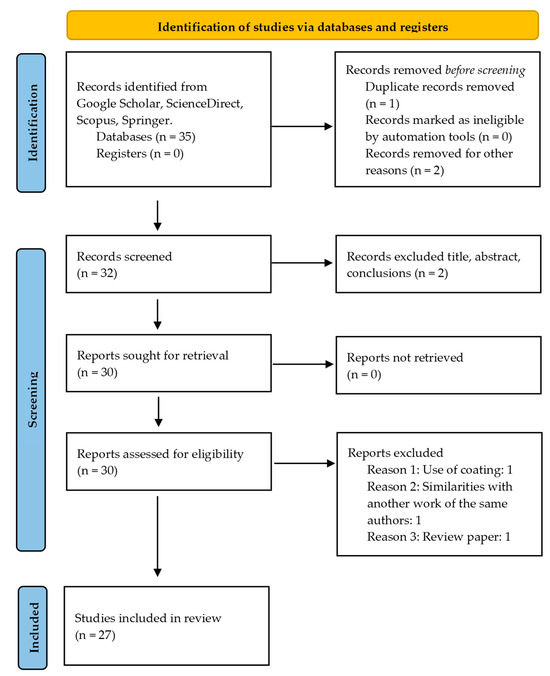
Figure 1.
Flow chart according to PRISMA guidelines [24].
Once enough papers were chosen, the selected papers were first analyzed and classified according to the main categories of post-treatments: HT, ST and MT. Subsequently, the specific treatments applied were identified, as well as the outputs investigated. In detail, three main outputs, such as tensile properties, surface roughness, porosity etc., were considered to evaluate the effects of the post-treatment processes. Figure 2a reports an overview of the main categories of post-treatment processes adopted in the analyzed papers. Figure 2b, instead, shows the specific techniques and their frequency.
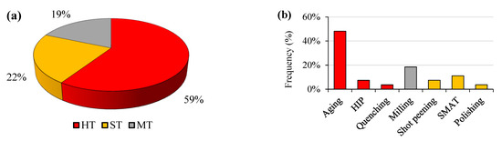
Figure 2.
(a) Pie chart of the main post-treatment processes adopted. (b) Specific post-treatment processes mentioned in the analyzed papers. The colors of the bars are derived from the pie chart. HIP refers to Hot Isostatic Pressing and SMAT refers to Surface Mechanical Attrition Treatment.
2.1. Heat Treatments
2.1.1. Aging Treatment
The AM metal parts possess a unique microstructure and residual stresses. Therefore, conventional heat treatments are often applied to homogenize the microstructure and reduce these stresses, in addition to tailoring the overall material properties [25]. Heat treatments are the most frequent and effective techniques used to overcome the limits of the MEX/M parts, as shown in Figure 2a. In detail, based on the current literature, the “aging” treatment covers ≈50% of the post-treatment processes adopted (see Figure 2b). Other heat treatments such as Hot Isostatic Pressing (HIP) and quenching are less adopted. The predominance of aging is related to the availability of heat-treatable materials as feedstock for MEX/M, such as the precipitation-hardened martensitic stainless steel (e.g., 17.4 PH). Indeed, as reported in Figure 3, more than 50% of the works mentioning a post-treatment process refer to 17-4 PH stainless steel.
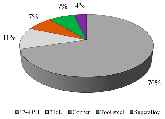
Figure 3.
Materials under investigation for post-treatment processes on MEX/M.
According to the relative standard ASTM A564 [26], aging treatments on 17-4 PH stainless steel are performed after a solutioning treatment (SHT) at 1040 °C for 0.5–1 h. However, aging can be performed without prior solutioning, and in this case it is called “direct aging”.
Abe et al. [27] and Bouaziz et al. [28] applied aging on 17-4 PH parts. In both works, the authors considered the H900 treatment (482 °C for 1 h) with a prior solutioning treatment and compared the properties of the as-sintered parts and the aged parts in terms of tensile properties. The H900 condition is named “peak hardening” condition because the highest values of tensile strength and hardness are reached. Indeed, according to the standard, the minimum tensile strength is 1310 MPa, the minimum yield strength (YS) is 1170 MPa and minimum hardness is 40 HRC. Abe et al. [27] observed for different printing orientations (see Figure 4) an increase up to a maximum of 1100 MPa of ultimate tensile strength (UTS) starting from a range of 840–880 MPa. At the same time, as expected, the aged parts became more brittle, with a significant decrease in elongation. Bouaziz et al. [28], instead, using the proprietary system ADAM, observed an increase in UTS of 16% in the aged parts compared to the sintered ones. Furthermore, the surface roughness was evaluated. A slight increase in average roughness (Ra) from 4.1 μm to 4.6 μm was obtained, possibly due to the thin external oxide layer generated on the surface after the HT.
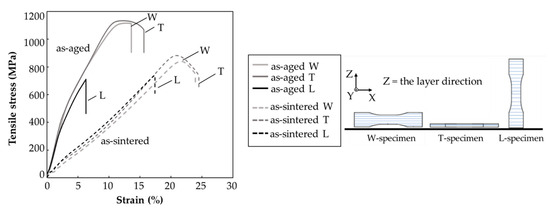
Figure 4.
Tensile test curves in the as-sintered condition and the aged one for the different printing orientations. W = on-edge, T = flat and L = upright. Adopted from [25].
Akessa et al. [29] investigated the response of 17-4 PH parts, varying the holding time (0 h, 0.5 h or 1 h) of SHT before the hardening stage H900 treatment and the cooling phase (air or water). Authors described a notable increase in UTS, up to 1078 MPa, and in YS, up to 921 MPa, when the parts were solutioned at 1038 °C for 0.5 h, aged and cooled with water. Indeed, cooling with water after H900 aging produced parts with a significantly higher YS compared to the parts cooled in air. In detail, YSs equal to 513 MPa (SHT time = 0.5 h) and 602 MPa (SHT time = 1.0 h) were observed for cooling in air, instead of 921 MPa (SHT time = 0.5 h) and 892 MPa (SHT time = 1 h) for cooling in water. However, the highest value of hardness (417 ± 29 HV) was recorded with prior solutioning for 1 h and cooling in air. Another aspect often considered is the effect of the heat treatment on the residual porosity of the parts. Different authors analyzed how after a specific heat treatment the porosity in the parts changes. Pellegrini et al. [30] heat-treated 17-4 PH parts fabricated through different industrial extrusion-based technologies, such as ADAM, BMD and traditional MEX filament-based technology. The H900 (482 °C for 1 h) and H1150 (620 °C for 4 h) conditions were adopted and investigated for their effects on hardness and porosity. The H1150 condition, referred to as ’overaging,“ provides the highest ductility, accompanied by a corresponding decrease in hardness. Following the two aging treatments, hardness changed notably, particularly after H900, compared to H1150. More significant, however, was the effect on porosity. Indeed, the heat treatment reduced porosity from −1.5% to −34.3% compared to the as-sintered condition. Less significant were the differences in porosity observed by Go et al. [21] after SHT + H900. However, as observed also in the previous works, the mechanical response registered a significant increase in UTS (+9.3%), YS (+24.9%) and hardness (+17.6%), but also of the elongation (+26.7%).
Liew et al. [31] derived from the aging treatment (H900 and H1150) interesting results relating to UTS (1235 MPa) after H900, and to an elongation of 10.9% (≈+203% higher than the as-sintered condition) after H1150. These significant variations, as is widely discussed in the literature, are due to the enrichment of copper (Cu) precipitates in the matrix [30,32,33]. In Figure 5a,b, the matrix of 17-4 PH parts with a significant enrichment in copper can be seen. From the chemical mapping emerged the tendency of Cu-precipitates to deposit on the grain boundaries (see Figure 5b). However, when increasing the aging temperature and aging time, the Cu-precipitates tend to be coarse, favoring the increase in ductility. On the other hand, authors [31] found a notable result related to the pitting corrosion resistance that increased with the aging treatment, compared to the as-sintered condition. In detail, when overaged the highest pitting potential (Epit) is achieved.
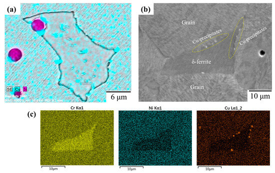
Figure 5.
(a) Chemical mapping of copper and silicon on 17-4 PH that is H900-heat-treated [34]. (b) Image of microstructure of a 17-4 PH and (c) relative chemical maps [30].
With the aim of making a comparison of the above mentioned results, Figure 6 reports the UTS achieved in the as-sintered on 17-4 PH parts after SHT + H900. Despite receiving the same post-treatment process procedure, notable differences were observed between the studies. Bouaziz et al. [28] reached the lowest UTS after SHT + H900 (825 MPa), despite Liew et al. [31] and Akessa et al. [29], using the same MEX/M technique (e.g., ADAM), reaching 1235 MPa and 1075 MPa, respectively. In the same way, in the work of Go et al. [21], the differences between as-sintered and aged were minimal (≈9.3%). In this case a different sintering procedure, due to the different feedstock, can alter the result of the aging process. Finally, as observed in [29], when water was used as cooling agent, a notable increase in strength was achieved due to the rapid cooling of the quenching and the arising of the martensite phase.
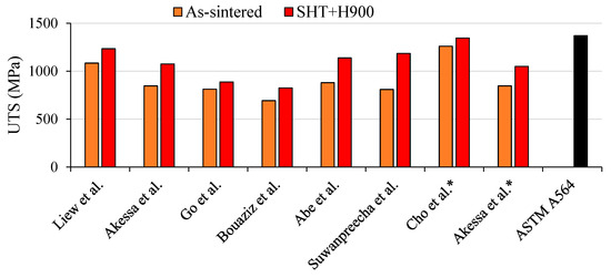
Figure 6.
Comparison of UTS values after SHT + H900 for 17-4 PH stainless steel [13,21,26,27,28,29,31,35]. * refers to a cooling in water.
Similarly, Forcellese et al. [34] exploited the intrinsic corrosion characteristic of the 17-4 PH material to understand how heat treatment can affect the localized corrosion resistance. Different printing orientations were investigated (orthogonal, parallel and 45° with respect to the printing bed). Authors observed how the 17-4 PH parts realized through BMD increased their corrosion resistance properties thanks to the heat treatment that favored the growth of the chromium-rich ferritic phase, improving the localized corrosion resistance properties.
Finally, based on investigation of the literature, Thompson et al. [18] reported the effect of aging treatment on a nickel-based alloy and, in particular, Inconel 718. Nickel-based alloys are heat-treatable as a PH martensitic stainless steel. In detail, a typical heat treatment for the superalloy consists of a solutioning at 980 °C for 1 h, air cooling and subsequent aging at 720 °C (8 h) and 620 °C (8 h) in air to tailor the microstructure, favoring the precipitation of niobium precipitates. Compared to the previous works on 17-4 PH, residual porosity remained in the parts, but a significant enhancing of the mechanical performance after the aging treatments was observed.
2.1.2. HIP and Other Heat Treatments
Hot Isostatic Pressing (HIP) is a well-known heat treatment fundamental to consolidating metal powder, increasing density and reducing porosity [23]. Generally, the process involves placing the part in a high-pressure furnace and subjecting it to both high temperature and uniform pressure from an inert gas such as argon (see Figure 7).
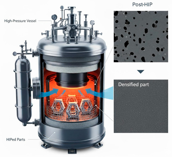
Figure 7.
Illustration of a HIP process. * The image was created through an AI assistant tool.
HIP is a crucial process for AM metal parts thanks to its capability to reduce porosity occurring during the manufacturing process. In this context, HIP for sinter-based processes such as the MEX/M can have a pivotal role. Nevertheless, the literature reports few examples about the use of HIP on MEX/M parts. Wang et al. [36] applied HIP for the first time on 316 L parts fabricated via MEX. As expected, the most significant result was in terms of porosity. Indeed, the authors decreased the porosity from 7.5% in the as-sintered parts to 0.3% in the HIPed parts, as reported in Figure 8a and 8b, respectively. Therefore, the reduction in porosity suggested an improvement in the mechanical properties, such as the tensile ones. Indeed, the UTS increased from 412 MPa to 540 MPa (+31%).
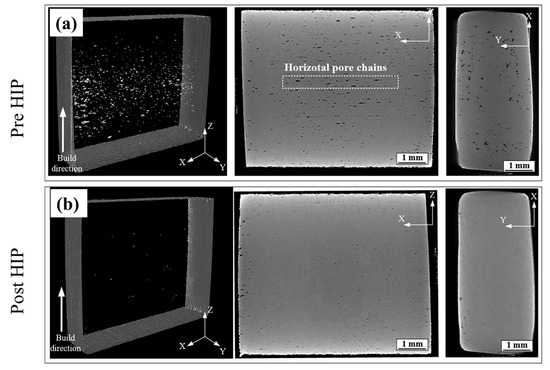
Figure 8.
CT image of (a) as-sintered parts pre-HIP and (b) as-sintered parts post-HIP. Adopted from [34].
Ajjarapu et al. [15] analyzed the effects of the HIP process on pure copper parts. As for the previous work, the HIPed parts achieved a density of 97.7%, leading to higher UTS (+10%), higher elongation (+40%) and a higher Young’s Modulus (+100%). Furthermore, the authors evaluated the intrinsic properties of copper such as the electrical conductivity, pre- and post-HIP. A dramatic increase in the electrical conductivity, close to 100% of IACS (International Annealing Copper Standard), was achieved thanks to the higher densification provided by the HIP process.
From Figure 2b, other heat treatments, such as quenching, have been less extensively investigated for metal parts fabricated via MEX. Generally, quenching is employed to increase the hardness of the metal through rapid cooling in water, oil, or gas. To reduce the brittleness introduced by quenching, a subsequent tempering step is often performed to enhance the toughness of the metal.
An example is reported by Naranjo et al. [37] on M2 tool steel produced through MEX technology. The authors heated MEX parts up to 1180 °C and performed oil quenching in the first step, followed by tempering at 525 °C in a secondary step. They highlighted the benefits of heat-treating the parts, noting that the microstructure became more homogeneous, with a phase transformation from austenite to martensite and an enrichment of carbides, which resulted in increased hardness. Hardness in the as-sintered condition was ≈45 HRC and moved up to ≈62 HRC after the quenching and tempering cycles. Finally, the authors analyzed the tribological properties of the as-sintered and heat-treated parts. M2 tool steel, indeed, is often adopted in highly complex working conditions. The heat-treated parts showed better tribological properties than the as-sintered counterparts thanks to a higher hardness that generated a higher coefficient of friction (CoF) and a lower wear rate (see Figure 9a and 9b, respectively). The wear effects on the surfaces for an as-sintered sample (Figure 9c) and a heat-treated one (Figure 9d) are reported.
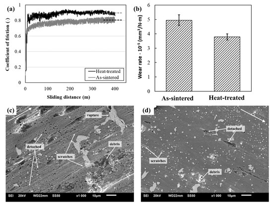
Figure 9.
(a) Coefficient of friction (CoF) comparison, (b) wear-rate values for as-sintered and heat-treated M2 samples, (c) wear track on M2 as-sintered and (d) wear track on heat-treated M2. Adopted from [35].
2.2. Surface Treatments
Regardless of the extrusion mechanism, the parts realized through MEX suffer from a poor surface quality due to the layer-wise effect generated by the deposition of layer upon layer. Indeed, the wrong choice of some printing parameters can influence the outer surfaces, generating undesired voids the deposited strands or between layers. As for the other Metal AM technologies, a rough surface, especially along printing orientation, can potentially affect the parts’ response by reducing the application window of the produced parts. In this context, surface post-treatment processes appear to be the best solutions to overcome these limitations. Various surface post-treatment processes have been applied to the metal parts fabricated in AM. However, considering the MEX/M, this area is still unexplored. In Figure 2a, the papers related to the surface post-treatment are only 16% of the total, and when including machining technology as well, the total is lower than 40%. The modification of the surface properties of MEX/M parts is performed exclusively through mechanical treatments. In detail, it is requested that a tool (e.g., cutting tool, media or granules) with determined characteristics, deforms, removes or finishes the material surface (Figure 10).
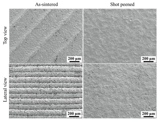
Figure 10.
Scanning Electron Microscope (SEM) image of an as-sintered sample on top and lateral faces and a shot peened one. Adopted from [13].
Based on Figure 2b, shot peening, surface mechanical attrition treatment (SMAT) and polishing were the adopted processes. In this section, the machining is excluded from the discussion because it will be discussed more deeply in a dedicated section.
A significant contribution to this topic was proposed by Suwanpreecha et al. [13]. In their work, they showed how different post-treatment processes can impact MEX parts’ characteristics. In detail, the authors used a shot peening process on 17-4 PH samples and evaluated different outputs such as surface roughness, tensile properties and fatigue strength. The comparison for the top surface and lateral surface between the as-sintered and shot-peened samples is reported in Figure 10. The shot peening process removed any potential characteristics of MEX parts. Indeed, the typical layer-wise effect (lateral view) was completely removed and the deposited strands were absent. In this context, the surface roughness (Ra) decreased dramatically from 6.60 ± 0.84 μm to 2.90 ± 0.14 μm on the top faces and from 15.80 ± 1.00 μm to 3.40 ± 0.30 μm on the lateral faces. Furthermore, the reduction in surface roughness allowed the sample to obtain a slight increase in tensile properties (+5.6% in UTS, +7.9% in YS) and significant improvement in fatigue strength (+46.2%). However, the authors obtain the best UTS, YS values and fatigue properties when the samples were shot peened and aged as reported in Figure 11a–c. These findings suggest how a combination of two or more post-treatment processes can be the right way to overcome the defects of the parts and the technological limitations of MEX/M.
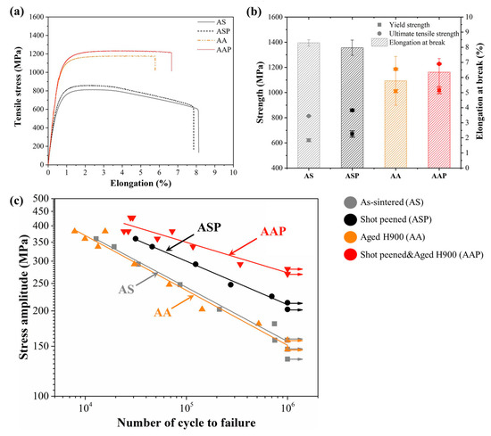
Figure 11.
Results comparison of (a) tensile test curves, (b) tensile properties and (c) fatigue test. Adopted from [13].
To improve the tensile properties and surface roughness of 17-4 PH parts, Chemkhi et al. [38] adopted the SMAT process, a variant of the shot peening process with a multitude of parameters. SMAT consists of the high-frequency vibration of spherical balls (see Figure 12a) that creates a nanocrystallized layer at the material surface. On the other hand, the shot peening process (see Figure 12b) is a cold working process that uses a stream of small shots to impact the material’s surface. Chemkhi et al. [38], through SMAT, observed a notable increase in UTS from 500 MPa to 700 MPa (+40%), along with a remarkable reduction (≈90%) in the roughness measured on the top faces. The notable increase in the UTS appeared to be strictly related to the reduction in Ra and potential superficial defects that can generate crack initiation in the part. Indeed, the multiple shots that impact on the surface increase the hardness of the material, induce compressive residual stresses [22] and modify the grain size. All these characteristics typical of a surface mechanical treatment can enhance the mechanical response of the parts. Gong et al. [39], similarly, applied the SMAT technique on 17-4 PH samples and investigated its effects under mechanical loading. Firstly, the UTS tended not to vary; instead, the elongation of the SMATed samples reduced due to the hardening of the material (from ≈2.6% to ≈2.1%). Significant results, instead, were observed in the surface porosity. Indeed, SMAT reduced the pore content on the surface, also known as “open porosity”, and their size in the initial stage under load (around 1.5% of strain). Over 1.5% of the strain, the pores closed through SMAT reopened and no differences between the as-sintered and the SMATed ones are observed. Finally, a significant impact of the SMAT was observed in the deformation mechanism and crack propagation thanks to the reduction in superficial defects, pores and surface roughness.
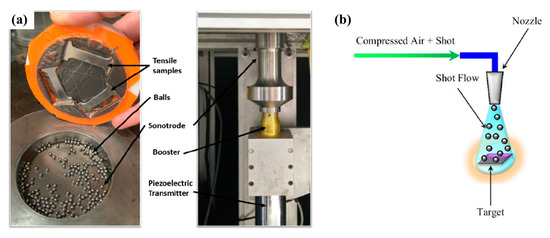
Figure 12.
(a) Representation of SMAT [38] and (b) shot peening process [22].
The SMAT process also appeared beneficial for the tribological and corrosion behavior of 17-4 PH parts. Indeed, the decrease in roughness (see Figure 13a,b) and the closing of the open porosities (Figure 13c) reduced the wear of the parts through abrasion and adhesion and at the same time avoided triggering of corrosion crevices. Naim et al. [40] indeed observed a reduced wear rate of the SMATed samples compared to the as-sintered ones. Furthermore, the corrosion properties, such as potential (Ecorrosion), current (Icorrosion) and localized potential (Elocalized) improved after SMAT.
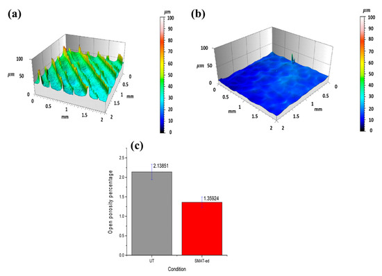
Figure 13.
Three-dimensional profile of sample in (a) as-sintered condition and (b) SMAT condition. (c) Comparison between as-sintered and SMATed sample in terms of open porosity. Adopted from [40].
As for the SMAT process, shot peening process parameters must be optimized to avoid undesired results. Hence, Suwanpreecha et al. [41] analyzed the effect of the shot peening time (5, 25, 50 and 75 min) on 316 L parts fabricated through BMD using hydroxyapatite as material media. After an initial decrease to 1.95 μm at 25 min, the Ra started to increase, becoming higher than the as-sintered condition at 75 min (2.57 μm versus 2.42 μm). However, at the highest exposure time, the best results in terms of microhardness and tribological properties (coefficient of friction and wear rate) were obtained thanks to the induced work hardening mechanism of the post-treatment process.
2.3. Machining Technologies
Machining technologies belong to conventional manufacturing (CM) processes, together with forging and casting. Despite AM technologies and CM technologies often having been considered alternatives to each other, their combination generated a new area of manufacturing called “hybrid manufacturing”. This hybridization consists of the adoption of CM technologies as post-treatment processes for parts manufactured through different AM technologies to satisfy geometric, dimensional and surface quality requirements [42]. Indeed, computer numerical control (CNC) machines are commonly used to remove metal parts produced by laser-based technologies from the printing bed. In a subsequent step, the parts are reworked using CNC machining to eliminate typical defects resulting from the additive process. In the industrial landscape, DMG Mori AG (Tokyo, Japan) is the pioneer and leader company in the hybrid manufacturing area. On the other hand, in the last decade the scientific community has deeply investigated this area, especially considering PBF-LB and DED-LB technologies.
Over the past five years, MEX/M has begun to adopt this hybrid approach. According to the available literature, milling is the preferred machining technique (see Figure 2b). In particular, CNC milling machines are employed for their high accuracy and repeatability, allowing the correction of manufacturing errors or achievement of the desired part dimensions.
CNC machining was adopted by Tecelli et al. [43] and Jansa et al. [12] in their respective works. Jansa et al. [12] adopted the CNC machining for each sample test, as reported in Figure 14. In addition, the authors observed how the machining provided significant improvements in the elastic modulus of the samples tested under a bending test (about two times) and in the flexural stress, which was about 8–11% higher than in the as-sintered condition.
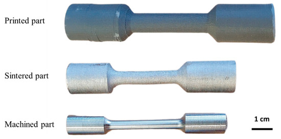
Figure 14.
Fatigue test sample after printing, sintering and machining. Adopted from [12].
Tecelli et al. [43] observed how the machined test samples reduced the initial surface roughness along the printing orientation (the most critical one) from 10.22 μm to 0.48 μm and enhance the UTS along each printing orientation as reported in Figure 15a,b. However, the improvement in Ra and UTS appeared lower compared to the machined and polished samples (0.08 μm and 1030 MPa, respectively), but higher if compared when the samples are machined and H900 aged. These results confirmed the observation in [13] that the combination of the post-treatment processes enhances the properties of the MEX/M parts.
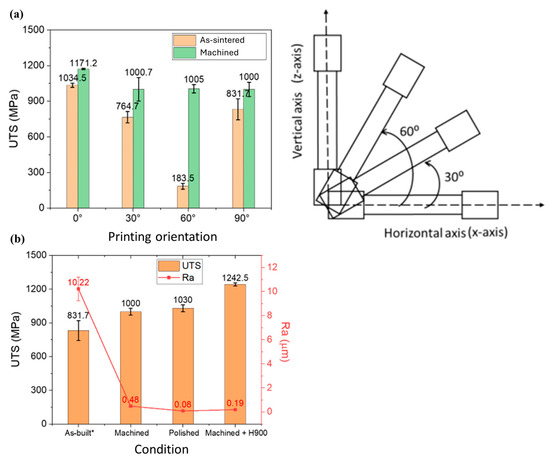
Figure 15.
(a) Comparison of UTS values for the different printing orientations in as-sintered condition (orange bar) and machined condition (green one). (b) 90° printing orientation: UTS and Ra values for the different conditions. Adopted from [43].
With respect to the previous work, Monzón et al. [44] reported an interesting approach for the hybrid manufacturing of MEX/M Cu-parts. The aim of their study was to provide an analysis of dimensional characteristics and surface characteristics of different types of test artifacts realized through ADAM technology. These parts belong to the standard ASTM 52902:2019. The process chain consisted of the printing, debinding and sintering of the artifacts, subsequent analysis of the reduced dimensions after sintering due to the shrinkage, computation of the oversizing factors for machining process and validation of the methodology. The results obtained allowed them to define the oversizing factors for a complex part in a hybrid manufacturing process chain (see Figure 16a). In Figure 16b, instead, the surface properties in terms of roughness (Ra, Ry and Rq) were evaluated pre- and post-machining treatment, and an overall decrease ≈81% was obtained.
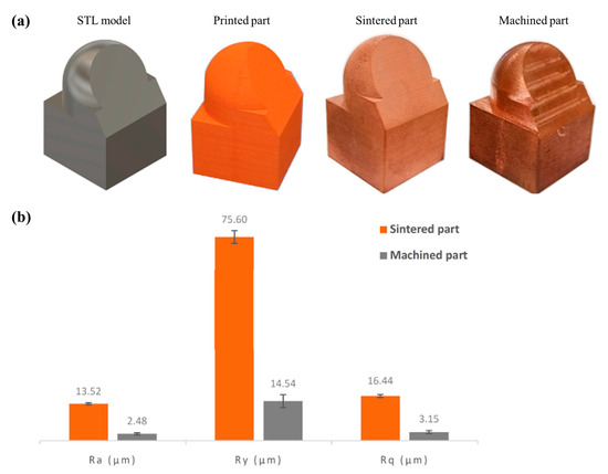
Figure 16.
(a) Different stages of the methodology. (b) Roughness parameter comparison (as-sintered vs. machined). Adopted from [44].
With respect to previous works, in the work of Kolomy et al. [14], the inadequate surface characteristics of the as-sintered parts were considered the main issue of the MEX/M parts for the industrial application fields. In this context, the authors reported a structured approach to define the best combination of cutting parameters for H13 parts fabricated through MEX/M and make the surface characteristics compliant to the strict industrial quality requirements. Cutting speed, feed per tooth and cooling were considered tunable process parameters for their work. After several tests, authors identified 80 m/min, 0.005 mm/tooth and flood cooling as best combinations. Indeed, a significant low Ra was obtained (0.08–0.09 μm) and the microhardness of the machined parts increased +20% with respect to the as-sintered condition. However, the authors reported that using flood cooling along with the highest cutting speed and feed per tooth resulted in the highest compressive residual stresses in the samples. Conversely, dry machining produced slightly higher surface roughness (Ra = 0.08–0.10 μm) but lower compressive residual stresses.
The comparison of the effects of surface roughness for the investigated post-treatment processes is reported in Table 1. The analyzed surface is considered due to the evident differences that MEX/M parts show between the lateral faces and the top face. When the authors did not specify the surface of analysis “n.d.” is reported.

Table 1.
Comparison of surface roughness values for different post-treatment processes.
In summary, significant improvements were observed after each post-treatment process, with a final Ra value in the range of 0.08–2.48 μm after machining, 0.04–0.46 μm after SMAT and slightly higher after shot peening at 1.95–3.40 μm. Polishing, instead, allowed the achievement of a final Ra equal to 0.08 μm, with the highest percentage variation (ΔRa%) being equal to −99.2% with respect to the as-sintered condition. The ΔRa% was calculated as the percentage variation in Ra before the post-treatment process and after.
2.4. Summary of the Results
In this section an overview of the analyzed and discussed papers is reported in Table 2. Below, a representative graph of the main investigated properties is reported in Figure 17.
Table 2.
Summary table of post-treatment process category and detail, material and main properties investigated for each author. HT (heat treatment), ST (surface treatment), MT (machine technology).
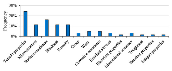
Figure 17.
Analysis of the investigated properties based on the analyzed literature.
3. Outlook and Industrial Applications
MEX/M technology is still undergoing intensive investigation across all its main phases, as researchers continue to optimize processes and mitigate the well-known limitations that characterize multi-step technologies. The adoption of post-treatment processes is recognized as a necessary step to overcome the inherent limitations of the MEX/M process chain. While a sequenced approach of two or more post-treatments has been shown in a few studies to combine and amplify individual process benefits, this expansion directly conflicts with management factors like production time and cost. Accordingly, the challenge for the combination of MEX/M and post-treatment processes lies in defining a critical balance between these technological benefits, the economic constraints and the environmental impact of the process chain.
Furthermore, the analyzed literature suggests a significant shift in the scientific community’s approach: post-treatment processes are no longer seen as a separate, optional step but are now considered essential to making MEX parts industrially viable and competitive. This evolution is driven by the recognition that post-processing is a critical tool for enhancing material properties and quality. A more advanced trend is the development of “in-process treatments”. Thanks to technological advancements and the integration of different enabling technologies, both industries and academia are exploring integrated manufacturing systems. Collaborative robots or other automated systems that combine the MEX printing process with a post-treatment step are currently under development or in the prototyping phase. This approach allows post-treatments to be implemented not as a separate workstation operation, but as a layer-by-layer, or quasi-layer-by-layer process, integrated into fabrication. In addition, in situ visual scanning systems able to monitor the deposited layers can further improve the industrial applicability of this technology.
4. Conclusions
The present review paper has dealt with the adoption of different types of post-treatment processes for metal parts realized through Material Extrusion (MEX/M). The adoption of post-treatment processes opens the possibility to enhance mechanical properties, tailor the microstructure, reduce the porosity and improve the surface roughness. Based on the analysis of the available scientific literature, heat treatment, surface treatment and machining are identified as the main post-treatments adopted. The predominance of heat treatment (they represent about 60% of the performed treatments on MEX/M parts) is strictly related to the characteristics of the feedstock material available for MEX/M, the easiness to perform and the relevant impact on material properties. Surface treatments are also commonly applied, and studies focused on enhancing surface finish and dimensional precision through machining play a key role in advancing hybrid manufacturing technologies. The implementation and optimization of hybrid processes enable the reduction or elimination of typical AM defects, while preserving their inherent advantages. Recently, considerable interest has emerged in these multi-step, integrated processes, which are effective in enhancing the performance of AM technologies. In this context, surface treatments and machining can be regarded as auxiliary techniques, even from an “in-process” perspective.
Funding
This work was partially supported by the project FRA 2021 “Analisi dei parametri tecnologici di Parti Realizzate in Metal FFF” and by the National Recovery and Resilience Plan (NRRP), Mission 4 Component 2 Investment 1.3—Call for tender No. 341 of 15 March 2022 of Italian Ministry of University and Research funded by the European Union—NextGenerationEU. Award Number: PE00000004, Concession Decree No. 1551 of 11 October 2022 adopted by the Italian Ministry of University and Research, CUP D93C22000920001, MICS (Made in Italy—Circular and Sustainable). Moreover this work was partially supported by the project AIM Accessories and intelligence in Master (ai sensi dell’art. 9 del Decreto del Ministro dello Sviluppo Economico del 9 December 2014 e ss.mm.ii.) Project number CDS0001283.
Data Availability Statement
No new data were created or analyzed in this study. Data sharing is not applicable to this article.
Acknowledgments
During the preparation of this manuscript, the authors used Gemini, 2.5 Flash for the purposes of generating a figure (Figure 7) embedded in this paper. The authors have reviewed and edited the output and take full responsibility for the content of this publication.
Conflicts of Interest
The authors declare no conflicts of interest.
References
- Gonzalez-Gutierrez, J.; Cano, S.; Schuschnigg, S.; Kukla, C.; Sapkota, J.; Holzer, C. Additive Manufacturing of Metallic and Ceramic Components by the Material Extrusion of Highly-Filled Polymers: A Review and Future Perspectives. Materials 2018, 11, 840. [Google Scholar] [CrossRef]
- Guerra, M.G.; Morfini, L.; Pellegrini, A.; Meng, F.; Lavecchia, F.; Ferraris, E.; Galantucci, L.M. Material Extrusion-Debinding-Sintering as an Emerging Additive Manufacturing Process Chain for Metal/Ceramic Parts Construction. In CIRP Novel Topics in Production Engineering; Springer: Berlin/Heidelberg, Germany, 2024; Volume 1, pp. 147–182. [Google Scholar] [CrossRef]
- Sun, X.; Mazur, M.; Cheng, C. A Review of Void Reduction Strategies in Material Extrusion-Based Additive Manufacturing. Addit. Manuf. 2023, 67, 103463. [Google Scholar] [CrossRef]
- Lotfizarei, Z.; Mostafapour, A.; Barari, A.; Jalili, A.; Patterson, A.E. Overview of Debinding Methods for Parts Manufactured Using Powder Material Extrusion. Addit. Manuf. 2023, 61, 103335. [Google Scholar] [CrossRef]
- Gonzalez-Gutierrez, J.; Godec, D.; Kukla, C.; Schlauf, T.; Burkhardt, C.; Holzer, C. Shaping, Debinding and Sintering of Steel Components via Fused Filament Fabrication. In Proceedings of the 16th International Scientific Conference on Production Engineering—CIM2017, Zadar, Croatia, 8–10 June 2017; pp. 99–104. [Google Scholar]
- Obadimu, S.O.; Kourousis, K.I. Shrinkage Behaviour of Material Extrusion Steel 316L: Influence of Primary 3D Printing Parameters. Rapid Prototyp. J. 2022, 28, 92–101. [Google Scholar] [CrossRef]
- German, R.M. Sintering Theory and Practice; Wiley: Hoboken, NJ, USA, 1996. [Google Scholar]
- Rios, A.C.; Hryha, E.; Olevsky, E.; Harlin, P.; Cabo, A.; Hryha, E.; Olevsky, E.; Harlin, P. Sintering Anisotropy of Binder Jetted 316L Stainless Steel: Part II—Microstructure Evolution during Sintering. Powder Metall. 2022, 65, 283–295. [Google Scholar] [CrossRef]
- Supriadi, S.; Suharno, B.; Hidayatullah, R.; Maulana, G.; Baek, E. Thermal Debinding Process of SS 17-4 PH in Metal Injection Molding Process with Variation of Heating Rates, Temperatures, and Holding Times. Solid State Phenom. 2017, 266, 238–244. [Google Scholar] [CrossRef]
- Singh, G.; Missiaen, J.M.; Bouvard, D.; Chaix, J.M. Additive Manufacturing of 17-4 PH Steel Using Metal Injection Molding Feedstock: Analysis of 3D Extrusion Printing, Debinding and Sintering. Addit. Manuf. 2021, 47, 102287. [Google Scholar] [CrossRef]
- Singh, G.; Missiaen, J.M.; Bouvard, D.; Chaix, J.M. Copper Extrusion 3D Printing Using Metal Injection Moulding Feedstock: Analysis of Process Parameters for Green Density and Surface Roughness Optimization. Addit. Manuf. 2021, 38, 101778. [Google Scholar] [CrossRef]
- Jansa, J.; Volodarskaja, A.; Hlinka, J.; Zárybnická, L.; Polzer, S.; Kraus, M.; Hajnyš, J.; Schwarz, D.; Pagáč, M. Corrosion and Material Properties of 316L Stainless Steel Produced by Material Extrusion Technology. J. Manuf. Process 2023, 88, 232–245. [Google Scholar] [CrossRef]
- Suwanpreecha, C.; Linjee, S.; Newyawong, P.; Yordsri, V.; Songkuea, S.; Wutikhun, T.; Manonukul, A. Effects of Aging and Shot Peening on Surface Quality and Fatigue Properties of Material Extrusion Additive Manufactured 17-4PH Stainless Steel. Mater. Des. 2024, 241, 112939. [Google Scholar] [CrossRef]
- Kolomy, S.; Maly, M.; Sedlak, J.; Zouhar, J.; Slany, M.; Hrabec, P.; Kouril, K. Machinability of Extruded H13 Tool Steel: Effect of Cutting Parameters on Cutting Forces, Surface Roughness, Microstructure, and Residual Stresses. Alex. Eng. J. 2024, 99, 394–407. [Google Scholar] [CrossRef]
- Ajjarapu, K.P.K.; Barber, C.; Taylor, J.; Pelletiers, T.; Jackson, D.; Beamer, C.; Atre, S.V.; Kate, K.H. Advancements in 3D Printing and Hot Isostatic Pressing of Copper: Bridging the Gap between Green and Sintered States for Enhanced Mechanical and Electrical Properties. Progress. Addit. Manuf. 2024, 9, 2343–2350. [Google Scholar] [CrossRef]
- Momeni, V.; Hufnagl, M.; Shahroodi, Z.; Poehle, G.; Gonzalez-Gutierrez, J.; Schuschnigg, S.; Kukla, C.; Holzer, C. 3D Printing of Aluminum Alloys via Material Extrusion (MEX) Process: Challenges in Developing Acetone-Soluble Binder Systems. Polym. Adv. Technol. 2025, 36, e70194. [Google Scholar] [CrossRef]
- Sun, X.; Zhang, M.; Dai, G.; Liang, Z.; Guo, Y.; Yang, Q.; Sun, Z.; Alexandrov, I.V. Microstructure Evolution and Mechanical Properties of Ti-6Al-4V Alloy Prepared by Fused Filament Fabrication. J. Alloys Compd. 2025, 1014, 178841. [Google Scholar] [CrossRef]
- Thompson, Y.; Zissel, K.; Förner, A.; Gonzalez-Gutierrez, J.; Kukla, C.; Neumeier, S.; Felfer, P. Metal Fused Filament Fabrication of the Nickel-Base Superalloy IN 718. J. Mater. Sci. 2022, 57, 9541–9555. [Google Scholar] [CrossRef] [PubMed]
- Meng, F.; Beretta, M.; Pellegrini, A.; Selema, A.; Sergeant, P.; Vleugels, J.; Galantucci, L.M.; Ferraris, E. Impact of Strand Deposition and Infill Strategies on the Properties of Monolithic Copper via Material Extrusion Additive Manufacturing. Addit. Manuf. 2024, 89, 104277. [Google Scholar] [CrossRef]
- Côté, R.; Demers, V.; Demarquette, N.R.; Charlon, S.; Soulestin, J. Performance of Different Material Extrusion 3D Printing Strategies in Improving Density and Dimensional Properties. Int. J. Adv. Manuf. Technol. 2025, 140, 4045–4061. [Google Scholar] [CrossRef]
- Go, A.; Jeon, E.S.; Moon, S.K.; Park, S.J. Fabrication of 17-4PH Stainless Steel by Metal Material Extrusion: Effects of Process Parameters and Heat Treatment on Physical Properties. Mater. Des. 2024, 248, 113471. [Google Scholar] [CrossRef]
- Maleki, E.; Bagherifard, S.; Bandini, M.; Guagliano, M. Surface Post-Treatments for Metal Additive Manufacturing: Progress, Challenges, and Opportunities. Addit. Manuf. 2021, 37, 101619. [Google Scholar] [CrossRef]
- Ge, J.; Pillay, S.; Ning, H. Post-Process Treatments for Additive-Manufactured Metallic Structures: A Comprehensive Review. J. Mater. Eng. Perform. 2023, 32, 7073–7122. [Google Scholar] [CrossRef]
- Page, M.J.; McKenzie, J.E.; Bossuyt, P.M.; Boutron, I.; Hoffmann, T.C.; Mulrow, C.D.; Shamseer, L.; Tetzlaff, J.M.; Akl, E.A.; Brennan, S.E.; et al. The PRISMA 2020 Statement: An Updated Guideline for Reporting Systematic Reviews. BMJ 2021, 372, n71. [Google Scholar] [CrossRef]
- Laleh, M.; Sadeghi, E.; Revilla, R.I.; Chao, Q.; Haghdadi, N.; Hughes, A.E.; Xu, W.; De Graeve, I.; Qian, M.; Gibson, I.; et al. Heat Treatment for Metal Additive Manufacturing. Prog. Mater. Sci. 2023, 133, 101051. [Google Scholar] [CrossRef]
- ASTM A564/A564M-19a; Standard Specification for Hot-Rolled and Cold-Finished Age-Hardening Stainless Steel. ASTM International: West Conshohocken, PA, USA, 2013; pp. 1–8. Available online: https://store.astm.org/a0564_a0564m-19a.html (accessed on 27 October 2025).
- Abe, Y.; Kurose, T.; Santos, M.V.A.; Kanaya, Y.; Ishigami, A.; Tanaka, S.; Ito, H. Effect of Layer Directions on Internal Structures and Tensile Properties of 17-4ph Stainless Steel Parts Fabricated by Fused Deposition of Metals. Materials 2021, 14, 243. [Google Scholar] [CrossRef]
- Bouaziz, M.A.; Djouda, J.M.; Chemkhi, M.; Rambaudon, M.; Kauffmann, J.; Hild, F. Heat Treatment Effect on 17-4PH Stainless Steel Manufactured by Atomic Diffusion Additive Manufacturing (ADAM). Procedia CIRP 2021, 104, 935–938. [Google Scholar] [CrossRef]
- Akessa, A.D.; Tucho, W.M.; Lemu, H.G.; Grønsund, J. Investigations of the Microstructure and Mechanical Properties of 17-4 PH Ss Printed Using a MarkForged Metal X. Materials 2022, 15, 6898. [Google Scholar] [CrossRef] [PubMed]
- Pellegrini, A.; Lavecchia, F.; Guerra, M.G.; Galantucci, L.M. Influence of Aging Treatments on 17-4 PH Stainless Steel Parts Realized Using Material Extrusion Additive Manufacturing Technologies. Int. J. Adv. Manuf. Technol. 2023, 126, 163–178. [Google Scholar] [CrossRef]
- Liew, Y.H.; Tan, A.; Salehi, M. Microstructural, Mechanical, and Electrochemical Corrosion Properties of Extrusion Additive Manufactured 17-4 Precipitation Hardenable Stainless Steel. J. Mater. Eng. Perform. 2024, 34, 18024–18038. [Google Scholar] [CrossRef]
- Hsiao, C.N.; Chiou, C.S.; Yang, J.R. Aging Reactions in a 17-4 PH Stainless Steel. Mater. Chem. Phys. 2002, 74, 134–142. [Google Scholar] [CrossRef]
- Viswanathan, U.K.; Banerjee, S.; Krishnan, R. Effects of Aging on the Microstructure of 17-4 PH Stainless Steel. Mater. Sci. Eng. 1988, 104, 181–189. [Google Scholar] [CrossRef]
- Forcellese, P.; Mancia, T.; Simoncini, M.; Bellezze, T. Characterization of Microstructure and Localized Corrosion Resistance of Heat-Treated 17-4 PH Stainless Steel Fabricated by Material Extrusion. Metals 2025, 15, 137. [Google Scholar] [CrossRef]
- Cho, Y.H.; Park, S.Y.; Kim, J.Y.; Lee, K.A. 17-4PH Stainless Steel with Excellent Strength–Elongation Combination Developed via Material Extrusion Additive Manufacturing. J. Mater. Res. Technol. 2023, 24, 3284–3299. [Google Scholar] [CrossRef]
- Wang, Y.; Zhang, L.; Li, X.; Yan, Z. On Hot Isostatic Pressing Sintering of Fused Filament Fabricated 316L Stainless Steel—Evaluation of Microstructure, Porosity, and Tensile Properties. Mater. Lett. 2021, 296, 129854. [Google Scholar] [CrossRef]
- Naranjo, J.A.; Berges, C.; Gallego, A.; Herranz, G. A Novel Printable High-Speed Steel Filament: Towards the Solution for Wear-Resistant Customized Tools by AM Alternative. J. Mater. Res. Technol. 2021, 11, 1534–1547. [Google Scholar] [CrossRef]
- Chemkhi, M.; Djouda, J.M.; Bouaziz, M.A.; Kauffmann, J.; Hild, F.; Retraint, D. Effects of Mechanical Post-Treatments on Additive Manufactured 17-4PH Stainless Steel Produced by Bound Powder Extrusion. Procedia CIRP 2021, 104, 957–961. [Google Scholar] [CrossRef]
- Gong, C.; Marae Djouda, J.; Hmima, A.; Gaslain, F.; Maurer, T.; Panicaud, B. Analysis of the Effect of Surface Mechanical Attrition Treatment on the Mechanical Properties of 17-4 PH Stainless Steel Obtained by Material Extrusion. Prog. Addit. Manuf. 2025, 10, 755–773. [Google Scholar] [CrossRef]
- Naim, M.; Chemkhi, M.; Alhussein, A.; Retraint, D. Effect of Post-Treatments on the Tribological and Corrosion Behavior of 17–4PH Stainless Steel Processed via Fused Filament Fabrication. Addit. Manuf. Lett. 2023, 7, 100158. [Google Scholar] [CrossRef]
- Suwanpreecha, C.; Wiratkapun, K.; Sakkaeo, A.; Songkuea, S.; Parsompech, N.; Manonukul, A. Enhancing Surface Properties and Wear Performance of Material Extrusion Additively Manufactured 316L Stainless Steel Through Fine Particle Shot Peening with Hydroxyapatite for Biomedical Applications. Metall. Mater. Trans. A Phys. Metall. Mater. Sci. 2025, 56, 1429–1448. [Google Scholar] [CrossRef]
- Pragana, J.P.M.; Sampaio, R.F.V.; Bragança, I.M.F.; Silva, C.M.A.; Martins, P.A.F. Hybrid Metal Additive Manufacturing: A State–of–the-Art Review. Adv. Ind. Manuf. Eng. 2021, 2, 100032. [Google Scholar] [CrossRef]
- Tecelli, T.; Andrew, O.; Juan, B.; Ahuir, I.; Hiren, T.; Kotadia, R.; Williams, S.T. The Effect of Surface Finish and Post—Processing on Mechanical Properties of 17-4 PH Stainless Steel Produced by the Atomic Diffusion Additive Manufacturing Process (ADAM). Int. J. Adv. Manuf. Technol. 2024, 130, 4053–4066. [Google Scholar] [CrossRef]
- Monzón, E.; Bordón, P.; Paz, R.; Monzón, M. Dimensional Characterization and Hybrid Manufacturing of Copper Parts Obtained by Atomic Diffusion Additive Manufacturing, and CNC Machining. Materials 2024, 17, 1437. [Google Scholar] [CrossRef]
- Di Pompeo, V.; Santoni, A.; Santecchia, E.; Spigarelli, S. On the Short-Term Creep Response at 482 °C (900 °F) of the 17-4PH Steel Produced by Bound Metal Deposition. Metals 2022, 12, 477. [Google Scholar] [CrossRef]
- Zhang, Y.; Roch, A. Fused Filament Fabrication and Sintering of 17-4PH Stainless Steel. Manuf. Lett. 2022, 33, 29–32. [Google Scholar] [CrossRef]
Disclaimer/Publisher’s Note: The statements, opinions and data contained in all publications are solely those of the individual author(s) and contributor(s) and not of MDPI and/or the editor(s). MDPI and/or the editor(s) disclaim responsibility for any injury to people or property resulting from any ideas, methods, instructions or products referred to in the content. |
© 2025 by the authors. Licensee MDPI, Basel, Switzerland. This article is an open access article distributed under the terms and conditions of the Creative Commons Attribution (CC BY) license (https://creativecommons.org/licenses/by/4.0/).