Article

A Multimodal Fusion Method for Weld Seam Extraction Under Arc Light and Fume Interference

1
School of Artificial Intelligence, Henan Institute of Science and Technology, Xinxiang 453000, China
2
School of Computer Science and Technology, Henan Institute of Science and Technology, Xinxiang 453000, China
*
Author to whom correspondence should be addressed.
J. Manuf. Mater. Process. 2025, 9(11), 350; https://doi.org/10.3390/jmmp9110350
Submission received: 2 October 2025 / Revised: 23 October 2025 / Accepted: 23 October 2025 / Published: 26 October 2025

Abstract

During the Gas Metal Arc Welding (GMAW) process, intense arc light and dense fumes cause local overexposure in RGB images and data loss in point clouds, which severely compromises the extraction accuracy of circular closed-curve weld seams. To address this challenge, this paper proposes a multimodal fusion method for weld seam extraction under arc light and fume interference. The method begins by constructing a weld seam edge feature extraction (WSEF) module based on a synergistic fusion network, which achieves precise localization of the weld contour by coupling image arc light-removal and semantic segmentation tasks. Subsequently, an image-to-point cloud mapping-guided Local Point Cloud Feature extraction (LPCF) module was designed, incorporating the Shuffle Attention mechanism to enhance robustness against noise and occlusion. Building upon this, a cross-modal attention-driven multimodal feature fusion (MFF) module integrates 2D edge features with 3D structural information to generate a spatially consistent and detail-rich fused point cloud. Finally, a hierarchical trajectory reconstruction and smoothing method is employed to achieve high-precision reconstruction of the closed weld seam path. The experimental results demonstrate that under severe arc light and fume interference, the proposed method achieves a Root Mean Square Error below 0.6 mm, a maximum error not exceeding 1.2 mm, and a processing time under 5 s. Its performance significantly surpasses that of existing methods, showcasing excellent accuracy and robustness.

1. Introduction

Ring-shaped structural components are widely used in critical fields such as nuclear power, aerospace, and pressure vessels, where weld quality directly impacts overall structural safety and service life [1]. As high-end equipment manufacturing demands increasingly stringent welding quality and automation levels, welding robots are progressively replacing traditional manual welding, particularly excelling in complex trajectory scenarios like spatial closed curves. In such applications, precise identification and trajectory extraction of closed-curve welds constitute the primary prerequisite for achieving high-quality robotic welding while also serving as a crucial foundation for subsequent path planning and adaptive control [2].
However, the traditional weld trajectory generation methods, whether through manual teaching or offline programming before welding, generate fixed initial trajectories [3]. The fundamental limitation of such approaches lies in their inability to adapt to dynamic changes during welding, such as thermal deformation and stress release caused by high temperatures [4]. Once welding commences, the preset path often fails to adapt to the actual positional changes of the weld, leading to diminished weld quality. Therefore, to achieve truly high-precision automated welding, it is necessary to shift from “pre-welding planning” to “guidance during welding”, that is, to perceive the true shape of the weld in real time during the welding process.
In practice, when using arc welding processes such as GMAW, the online sensing system faces severe challenges from multiple dynamics [5,6]. As shown in Figure 1, intense arc light causes local overexposure and edge blurring in RGB images [7]. Dense fumes not only obscure visual information but also severely disrupt 3D point cloud acquisition, leading to missing points and noise. These interferences collectively weaken weld seam visual features and cause spatial information loss, significantly limiting the accuracy and robustness of the “weld-in-progress guidance” mode.
To achieve robotic automated welding, precise and robust weld seam trajectory extraction is a core prerequisite. In recent years, scholars worldwide have conducted extensive research on this issue. Based on the type of sensor data relied upon, mainstream approaches can be categorized into three technical pathways: methods based on 2D images, methods based on 3D point clouds, and methods based on multimodal fusion.
In the field of robotic welding, 2D vision-based seam perception stands as one of the most extensively researched and mature technical approaches. Early studies primarily relied on conventional image processing algorithms, which located the weld seam by analyzing hand-crafted features such as edges and textures in the weld zone [8,9]. However, this type of method is extremely sensitive to dynamic interferences such as strong arc light, metal reflections, and fumes that are common in the welding process, resulting in serious deficiencies in its robustness and generalization capabilities. To overcome the limitations of these traditional algorithms, deep learning techniques centered on Convolutional Neural Networks (CNNs) have emerged and rapidly become the dominant paradigm. For semantic segmentation tasks, U-Net and its variants have been widely adopted due to their efficient encoder–decoder architecture [10]. Meanwhile, advanced architectures such as DeepLabv3+ achieve high-precision detection by incorporating dilated convolutions to capture multi-scale contextual information [11]. To further distinguish between individual weld seam instances, two-stage instance segmentation networks, such as Mask R-CNN, are employed for more refined contour extraction [12]. To meet the real-time requirements of robotic welding, single-stage instance segmentation methods such as YOLACT and YOLO-seg [13,14] achieve faster inference speeds while maintaining high accuracy.
To address the lack of depth information in pure 2D vision, weld seam extraction methods based on 3D point clouds have emerged. This technology directly captures the 3D geometric information of the workpiece surface, offering inherent robustness to lighting variations while accurately reconstructing the spatial pose of weld seams. Consequently, it has garnered significant attention in the field of automated welding. The core of existing 3D methods lies in identifying the unique geometric features of weld seams, which can be categorized into traditional approaches and deep learning methods. Traditional approaches primarily rely on prior knowledge, such as local geometric properties of point clouds. For instance, Zhang et al. [15] proposed a feature descriptor based on Local Oriented Bounding Boxes (LOBBs), combined with K-means clustering to robustly extract general geometric features like edges and corners of workpieces, providing a basis for preliminary weld region localization. Fang et al. [16] employed a stereo vision system to enhance imaging contrast in narrow weld regions via gray-level expectation optimization, and then reconstructed high-precision weld point clouds using triangulation. Deep learning-based methods, however, automatically learn abstract geometric features of welds through data-driven approaches to handle more complex scenarios. For instance, Wang et al. [17] proposed the WeldNet architecture, which performs end-to-end circular weld detection by voxelizing point clouds and employing sparse convolutions with a Region Proposal Network (RPN), maintaining high recognition rates even in highly noisy environments. Kim et al. [18] designed a multi-view fusion framework to address occlusion issues. By registering local weld point clouds captured from different perspectives, they reconstruct complete, continuous weld trajectories. However, while 3D point clouds can precisely represent spatial structures, they remain susceptible to noise, occlusion, and sparsity in highly disturbed environments, resulting in insufficient detail capture capabilities.
To overcome the inherent limitations of single-modal perception and leverage the rich semantic information of 2D images alongside the precise spatial geometric data of three-dimensional point clouds, multimodal fusion has emerged as a critical technological pathway for achieving robust perception in complex environments. In domains such as autonomous driving, integrating lidar and camera imagery has become a mature solution for enhancing environmental understanding [19,20]. In the field of welding, multimodal fusion similarly demonstrates significant potential. For instance, to address the complex surfaces of irregularly structured workpieces, Zhang et al. [21] proposed an innovative weld seam extraction method. This approach deeply integrates semantic segmentation with point cloud features to precisely extract weld seam feature points. Ultimately, curve fitting is employed to reconstruct the weld seam, achieving high-precision extraction even on complex geometries. Similarly, Wu et al. [22] developed an extraction algorithm combining 2D depth images and 3D point clouds for automated bicycle frame welding. Jiang et al. [23] introduced SIMNet, a multimodal fusion network that innovatively integrates molten pool images with welding acoustic signals to enable real-time, quantitative prediction of weld back width.
Despite these advancements, most existing research has failed to systematically address the extreme challenges posed by the concurrent presence of arc light and fumes in welding processes like GMAW. In such scenarios, 2D images suffer from information distortion due to arc light-induced overexposure, while 3D point clouds are rendered incomplete by fume occlusion. The data quality from both modalities degrades simultaneously and dynamically across different spatial regions, which places exceptionally high demands on the robustness of any fusion algorithm.
To address the aforementioned challenges, this paper proposes a multimodal fusion method for weld seam extraction under arc light and fume interference, enabling high-precision, fully automated trajectory generation without reliance on manual teach-in programming. The primary contributions of this work include the following:
  • Proposing a collaborative fusion module for weld seam edge feature extraction (WSEF). By designing a multi-task learning framework that couples arc light suppression with semantic segmentation, it accurately segments the workpiece and substrate mask from disturbed images and robustly locates pixel-level edges of the weld seam based on the intersecting regions of the masks.
  • Designing a Local Point Cloud Feature extraction module guided by image–point cloud mapping (LPCF). This module precisely guides and constrains the processing region of 3D point clouds using 2D semantic masks. Combined with an enhanced PointNet++ network, it improves feature expression robustness against point cloud noise and occlusions.
  • Construct a cross-modal attention-driven multimodal feature fusion module (MFF). By introducing a cross-modal attention mechanism, it adaptively fuses 2D contour features with 3D point cloud structural features, generating a spatially consistent, detail-rich fused point cloud representation.
  • Proposes a hierarchical trajectory reconstruction and smoothing method. Through unsupervised clustering, principal component analysis-based ordering, and Fourier series fitting, it achieves topological reconstruction of discrete point sets, generating continuous, smooth, high-quality weld trajectories directly executable by robots.

2. Methodology

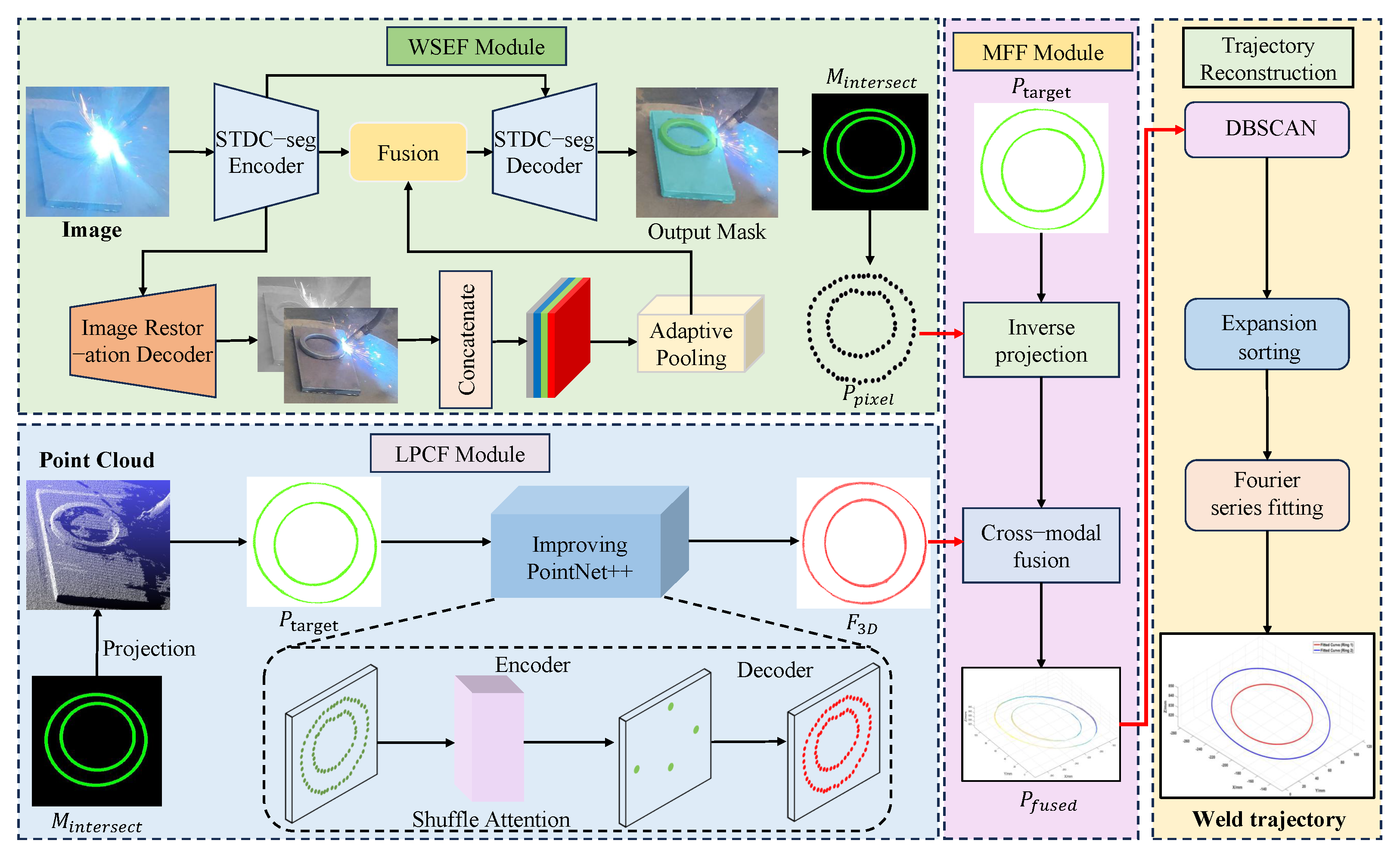
To achieve high-precision, robust extraction of circular closed-curve welds in arc light and fume environments, this paper proposes a generalized multimodal fusion perception and reconstruction method using a typical circular workpiece as the starting point. By integrating 2D visual details with 3D structural information, this method effectively overcomes perception uncertainties caused by welding disturbances such as arc light and fumes, achieving an end-to-end extraction process from raw sensor data to robot-executable trajectories. As shown in Figure 2, the overall framework comprises four core components: the WSEF module, the LPCF module, the MFF module, and the weld seam trajectory reconstruction and smoothing method. First, the WSEF module performs instance segmentation on the workpiece and substrate to extract precise 2D weld seam contours. Subsequently, the LPCF module locates the weld region within the raw point cloud based on the 2D mask and utilizes an enhanced PointNet++ architecture to extract robust 3D local features. Next, the MFF module fuses the 2D edges and 3D features through a cross-modal attention mechanism, forming a unified and rich spatial feature representation. Finally, high-order continuous reconstruction and smoothing optimization of the trajectory are achieved via Fourier series fitting, outputting a weld trajectory directly usable for robotic motion planning. This chapter will detail the algorithmic structure and technical implementation of each module.

2.1. Weld Seam Edge Feature Extraction Module for Collaborative Fusion Networks

During the welding process, intense arc light interference is the primary factor causing degradation in RGB image quality, resulting in localized overexposure and feature blurring in the edge regions of circular workpiece welds. Additionally, diffuse fumes reduce overall image contrast, further complicating edge extraction. To address these challenges, this paper proposes a WSEF module. The guiding ideology of this module is a multi-task learning framework that synergistically couples the arc light removal task with the semantic segmentation task to achieve mutual enhancement.
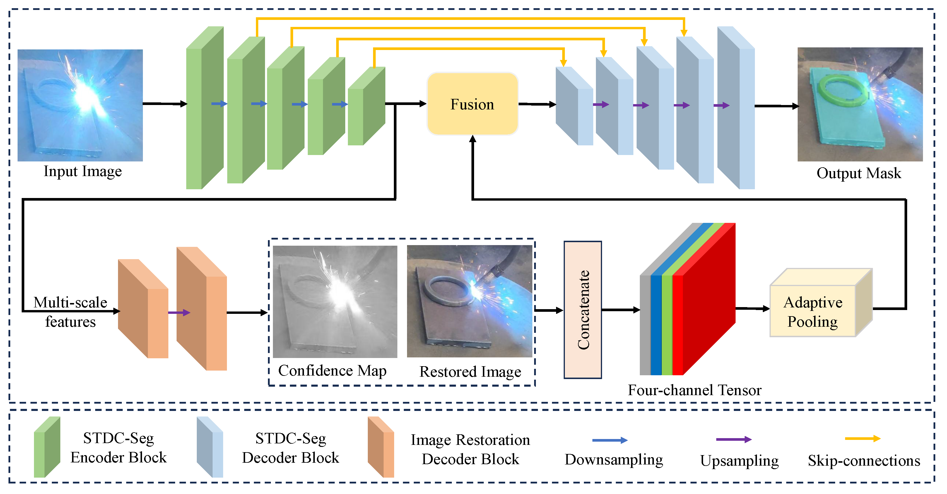
The overall architecture, as shown in Figure 3, comprises a shared encoder backbone, an arc light suppression branch, and a segmentation branch. The shared encoder backbone adopts the STDC-Seg network [24], which strikes an effective balance between speed and accuracy. The core principle is that for the network to perform high-precision segmentation, it must first effectively remove the overexposure to restore the underlying structural details. The segmentation task, in turn, provides a strong supervisory signal that forces the image restoration branch to generate feature representations that are not just visually plausible but also beneficial for accurately locating weld seam edges.
The implementation of this principle relies on the network’s structure and a joint loss function. The arc light removal branch, inspired by AOD-Net [25], outputs two key results: a restored 3-channel RGB image and a single-channel arc confidence map. This map is produced by a lightweight convolutional head that is trained implicitly through the joint optimization of the primary segmentation and restoration tasks. It functions as a crucial spatial attention prior for the segmentation network by explicitly indicating which image regions are unreliable due to overexposure.
This collaborative mechanism is optimized through end-to-end joint training. The overall objective function for the WSEF module, L WSEF , is a weighted sum of a segmentation loss ( L seg ) and an image restoration loss ( L res ):
L WSEF = λ seg L seg + λ res L res ,
where λ seg and λ res are weighting coefficients to balance the two tasks. The segmentation loss, L seg , is the standard Cross-Entropy Loss, suitable for multi-class pixel classification. The image restoration loss, L res , is the L1 Loss, which is effective at preserving edge details in the restored image. This joint loss function ensures the removal of overexposure by compelling the network to generate a clear restored image (to minimize L res ) as a necessary prerequisite to achieving an accurate segmentation result (to minimize L seg ).
After obtaining high-precision masks for the annular workpiece and the medium-thickness plate substrate, this paper further extracts pixel-level edge point sets from the mask intersection region to ultimately achieve pixel-level positioning of the weld seam. Specifically, based on the medium-thickness plate substrate mask M b and the annular workpiece mask M r , the mask intersection region M intersect is extracted:
M intersect = M b M r B 3 × 3 ,
where ⊕ denotes a morphological dilation operation, while B 3 × 3 represents a 3 × 3 rectangular structural element used to compensate for segmentation boundary errors.
When both M b and M r labels are present within the 3 × 3 neighborhood of a pixel in the mask intersection region M intersect , that pixel is classified as an edge pixel. Based on this classification method, the final output is a pixel-level point set P pixel .

2.2. Image–Point Cloud Mapping-Guided Local Point Cloud Feature Extraction Module

When acquiring 3D point clouds, welding fumes constitute the primary source of interference, leading to significant data loss and the generation of outliers. Simultaneously, intense arc light may cause high reflectivity on specific material surfaces, disrupting depth camera measurements and introducing abnormal depth values. To overcome these 3D perception challenges, this paper proposes an LPCF module guided by image-to-point cloud mapping. Its core strategy employs the precise, interference-resistant 2D weld edge mask M intersect obtained in Section 2.1 to guide target region localization in 3D space. This cross-modal guidance effectively filters background noise and outliers caused by suspended fumes. Furthermore, the depth value screening mechanism designed within the module (retaining points with minimum depth values) not only eliminates suspended dust particles but also excludes anomalous depth points above the workpiece surface caused by arc light reflections. This significantly enhances the purity and geometric integrity of the target point cloud P target .
First, based on the mask M intersect generated in Section 2.1 and the original 3D point cloud P = { p i p i = ( x i , y i , z i ) } i = 1 N of the workpiece, the 2D image and 3D space are aligned using the camera’s intrinsic and extrinsic parameters. Using the camera’s internal parameter matrix K and external parameters [ R T ] , the 3D point cloud P is projected onto the image plane. The projection relationship is expressed as follows:
u i v i 1 = 1 z i K · [ R T ] · x i y i z i 1 .
For any projected point ( u i , v i ) , if its coordinates fall within the valid region of M intersect , the corresponding 3D point P i is marked as a weld candidate point, forming the candidate point set P weld :
P weld = { P i M intersect ( u i , v i ) = 1 } .
To eliminate mapping ambiguities caused by fume particle occlusion—where multiple 3D points (including genuine workpiece points and fume particle points) project onto the same pixel coordinate—the module incorporates a depth value filtering mechanism. Under this mechanism, only the point with the smallest depth value z i is retained. While unsuitable for complex geometries with deep grooves, this strategy is effective for the surface-level welds in this study, as fume particles typically float between the workpiece and the camera, resulting in larger depth values. After processing this step, the final target point cloud effectively filtered for fume interference is obtained and denoted as P target :
P target = { P i z i = min ( Z ( u i , v i ) ) } .
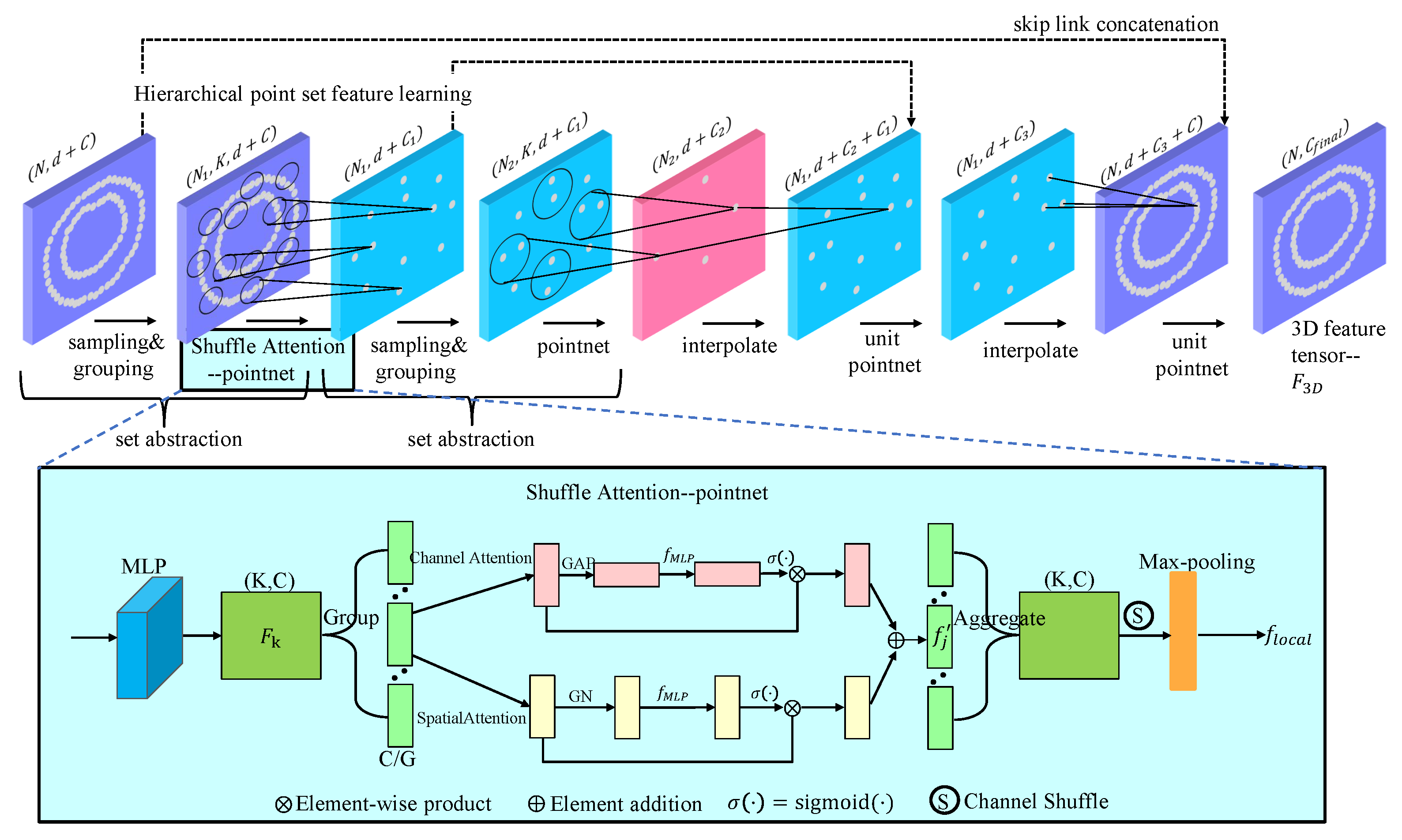
After obtaining the target point cloud P target , LPCF employs an improved hierarchical PointNet++ architecture to extract its local features [26]. The original PointNet++ employs max-pooling when aggregating neighborhood features. This operation treats all points within a neighborhood equally, making it highly sensitive to noise points caused by dust residue. To enhance feature extraction robustness, this paper embeds a Shuffle Attention (SA) module [27] into the first Set Abstraction layer of PointNet++. This attention mechanism adaptively assigns weights to points within the neighborhood, enabling the network to focus on critical geometric features while suppressing the influence of outlier noise points. This is crucial for processing sparse and uneven point clouds contaminated by fume residue. The specific structure is illustrated in Figure 4.
For a local neighborhood point set N k = { p j } j = 1 K defined by Farthest Point Sampling and Ball Query, the feature encoding process is as follows:
First, a shared-weight multi-layer perceptron (MLP), denoted as ψ mlp , elevates the raw features (e.g., coordinates and normals) of each point within the neighborhood to a higher-dimensional feature space, yielding the feature set F k = { f j = ψ mlp ( p j ) R C } j = 1 K . Specifically, this MLP consists of three fully connected layers with output feature dimensions of (64, 128, and 128), with each layer followed by a Batch Normalization and a ReLU activation function. This architecture is adapted from the original PointNet++ framework and was confirmed through preliminary experiments to be effective for extracting geometric features from the weld seam data. It is important to note that this MLP is not trained in isolation; it is an integral component of the LPCF module and is trained end-to-end as part of the entire model. The specific optimizer and parameters used for the overall training are detailed in Section 3.4.
Subsequently, the feature set F k is input into the Shuffle Attention module. This module first divides the C-dimensional feature channels into G groups. For each group of features, the channel attention weights w c R C G and spatial attention weights w s R K are computed in parallel.
w c = σ f MLP GAP F k , g ,
w s = σ f MLP GN F k , g ,
where F k , g denotes the features of group g, GAP represents global average pooling, GN stands for group normalization, and s i g m o i d is the sigmoid activation function. After attention weighting, the updated feature f j is
f j = f j w c f j w s ,
where ⊗ denotes element-wise multiplication, and ⊕ denotes element-wise addition.
After attention-weighted features from all groups are processed, a channel shuffle operation is performed to facilitate cross-group information flow. Finally, the weighted features within the neighborhood are aggregated via max pooling to generate the final robust feature descriptor f local for this local region:
f local = max j = 1 , , K Shuffle { f j } j = 1 K .
Subsequently, LPCF employs the decoder architecture of PointNet++ for feature propagation. Through interpolation and skip connections, abstract features from sparse point sets are upsampled and fused back to the resolution of the original target point cloud. After passing through all feature propagation layers, a dense, point-wise 3D feature tensor F 3 D is ultimately generated.
Each feature vector within F 3 D precisely encodes robust 3D geometric information for its corresponding point and its neighborhood, laying a solid foundation for high-precision multimodal fusion with 2D edge features, as described in Section 2.3.
It is important to note that the LPCF module, as a feature extractor, does not have its own separate, explicit loss function. Its guiding ideology is to produce robust geometric features from noisy point clouds. The design, particularly the integration of the Shuffle Attention mechanism, serves this purpose. The parameters of the improved PointNet++ network within this module are optimized implicitly through the end-to-end training of the entire model, guided by the final trajectory reconstruction accuracy at the end of the pipeline.

2.3. Cross-Modal Attention-Driven Multimodal Feature Fusion Module

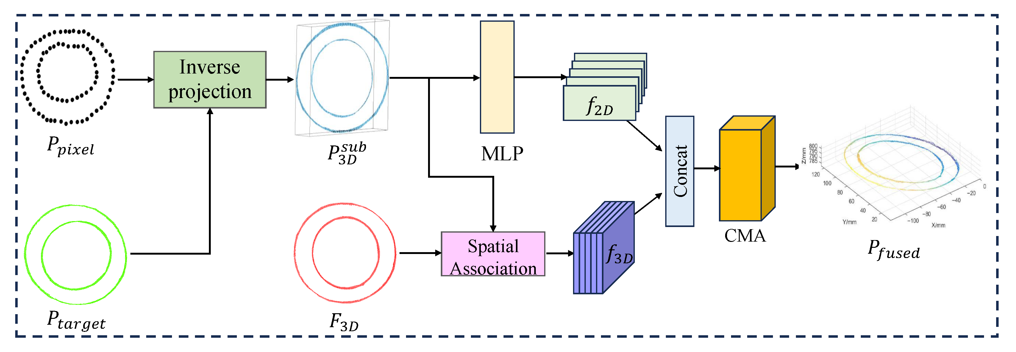
Arc light and welding fumes severely compromise both 2D and 3D perception quality during welding processes. To address this, the WSEF and LPCF modules in this paper suppress arc light interference in images and fume contamination in point clouds, respectively, generating high-precision 2D edge point sets (robust P pixel ) and robust 3D features ( F 3 D ). The MFF module aims to fuse these complementary features. Through cross-modal attention (CMA), it adaptively integrates the geometric precision of 2D edges with the structural authenticity of 3D point clouds, forming a fusion point cloud P fused that is resistant to mixed interference and rich in detail. This provides a robust data foundation for trajectory reconstruction. The overall workflow of this module is shown in Figure 5.
First, the set of edge points P pixel in the two-dimensional image coordinate system is back-projected into three-dimensional space using the camera projection model, constructing its corresponding three-dimensional point set P 3 D sub . Specifically, for each pixel point ( x e , y e ) P pixel , its 3D coordinates are obtained via inverse projection transformation by combining its depth information (derived from the target point cloud P target in Section 2.2):
x i y i z i = z i · K 1 · u i v i 1 ,
where ( u i , v i ) represents the image coordinates corresponding to the pixel point, and z i denotes the minimum depth value at the corresponding position. K is the camera intrinsic parameter matrix.
Subsequently, the point set P 3 D sub obtained from backprojection is spatially associated with the local point cloud features F 3 D extracted in Section 2.2. For each backprojected point, the k nearest point cloud feature points within its neighborhood are searched, and their corresponding three-dimensional feature vectors f 3 D R C are obtained through interpolation.
To fully integrate the geometric precision of 2D edges with the structural information of 3D point clouds, this paper employs a feature fusion network based on an attention mechanism [28]. For each associated point, its 2D pixel coordinate features are encoded into a 2D feature vector f 2 D R C via a lightweight MLP network. This vector is then concatenated with the corresponding 3D feature vector f 3 D to form a preliminary cross-modal feature f cat = [ f 2 D ; f 3 D ] .
Subsequently, f cat is fed into the CMA module, which adaptively learns the importance weights α = [ α 1 , α 2 ] for the two modalities and generates the final fused feature f fused :
α = Softmax ( MLP ( f cat ) ) ,
f fused = α 1 · f 2 D + α 2 · f 3 D .
Ultimately, each fused feature vector corresponds to a 3D position point, forming the fused point set P fused . This point set not only achieves pixel-level accuracy but also contains rich 3D geometric structure information. The guiding ideology of the MFF module is to achieve this high-quality fusion adaptively. The parameters of the CMA mechanism, which determine the fusion weights, are learned as part of the end-to-end training process rather than being governed by a standalone loss. The final trajectory reconstruction error, defined in Section 2.5, serves as the supervisory signal that optimizes the CMA’s parameters, allowing the module to learn the most effective fusion strategy. This ensures high consistency and robustness even in arc light and fume-filled environments, providing an accurate and dense data foundation for trajectory reconstruction.

2.4. Weld Path Reconstruction and Smoothing

Through multimodal feature fusion, the fused point cloud P fused was obtained, which possesses pixel-level 2D accuracy and rich 3D structural information. This point cloud exhibits a spatially discrete distribution and may contain multiple independent weld structures (e.g., inner and outer double rings). Affected by sensor noise and fusion errors, it is difficult to directly apply to robotic trajectory planning. To address this, this paper proposes a more general hierarchical trajectory reconstruction and smoothing method. It sequentially performs 3D spatial clustering segmentation, local coordinate system topological sorting, and parametric Fourier series fitting to achieve high-precision, smooth, and topologically correct weld seam trajectory reconstruction.
First, to achieve effective segmentation of annular welds in arbitrary spatial poses, this paper employs the unsupervised clustering algorithm DBSCAN (Density-Based Spatial Clustering of Applications with Noise). This algorithm clusters points directly in 3D space based on density distribution, robustly separating independent weld point sets (e.g., inner and outer rings) without requiring prior knowledge of weld quantity. Compared to traditional methods reliant on specific planar projections, DBSCAN exhibits greater robustness and geometric universality when handling workpieces in arbitrary orientations, as it is insensitive to the placement posture of the workpiece.
Subsequently, to establish an accurate topological order within each independent point cluster, a global ordering strategy based on Principal Component Analysis (PCA) [29] was employed. The principal plane of the point set was extracted via PCA, and the three-dimensional points were projected onto this plane to obtain a two-dimensional projected point set. The polar angle θ i of each point was calculated using the 2D centroid as the pole, and points were sorted accordingly. The order was then mapped back to the 3D point set, yielding the ordered point set P ordered . This method fully leverages the global geometric structure of the point set, overcoming the noise sensitivity of local nearest-neighbor methods and ensuring robust and accurate sorting.
Based on the ordered point set, parametric Fourier series are employed for closed trajectory fitting [30]. Using the polar angle θ as the natural parameter, the three-dimensional coordinates x , y , z are modeled as a Fourier series with respect to θ :
x ( θ ) = a 0 + k = 1 p ( a k cos ( k θ ) + b k sin ( k θ ) ) ,
y ( θ ) = c 0 + k = 1 p ( c k cos ( k θ ) + d k sin ( k θ ) ) ,
z ( θ ) = e 0 + k = 1 p ( e k cos ( k θ ) + f k sin ( k θ ) ) .
The coefficients were fitted using the least squares method, with a lower order (p = 2) selected to suppress noise and prevent overfitting. The inherent periodicity of the Fourier series ensures the closed-loop nature and high-order continuity ( C continuity) of the fitted curve.
The reconstructed trajectory not only accurately restores the three-dimensional geometry of the weld seam but also exhibits excellent smoothness and dynamic properties. This ensures smooth variations in velocity and acceleration during robotic motion, significantly reducing jitter and impact while enhancing process stability and weld quality. The trajectory can be directly converted into robotic control commands to drive the end-effector for high-precision automated welding operations.

2.5. Loss Function

The entire model is trained in an end-to-end fashion, guided by a total loss function that combines an intermediate supervision loss from the WSEF module with a final trajectory reconstruction loss.
The WSEF module is guided by the auxiliary loss, L WSEF , which is defined in Section 2.1. This intermediate loss helps the shared encoder learn robust features early in the training process.
The primary, end-to-end loss for the entire framework is the trajectory reconstruction loss, L trajectory . This function measures the difference between the final reconstructed trajectory ( P recon ), generated after the hierarchical reconstruction and smoothing process, and the ground truth trajectory ( P gt ). This loss is defined using the Mean Squared Error (MSE) of the corresponding 3D points:
L trajectory = 1 N i = 1 N P recon , i P gt , i 2 ,
where N is the number of points sampled from the trajectory. This loss is the final supervisory signal that is backpropagated through the entire network. It is responsible for optimizing the parameters of the intermediate modules, including the LPCF module (Section 2.2) and the MFF module (Section 2.3), by guiding them to produce features that minimize the final trajectory error.
The total loss for training the entire framework is a weighted sum of the final and intermediate losses:
L total = L trajectory + γ L WSEF ,
where γ is a hyperparameter that balances the contribution of the auxiliary WSEF task to the total training objective. This combined objective ensures that the network not only learns to perform the final task of accurate trajectory reconstruction but also benefits from the rich, detailed feature extraction encouraged by the intermediate image restoration and segmentation tasks.

3. Materials and Experimental Setup

3.1. Hardware Platform and Materials

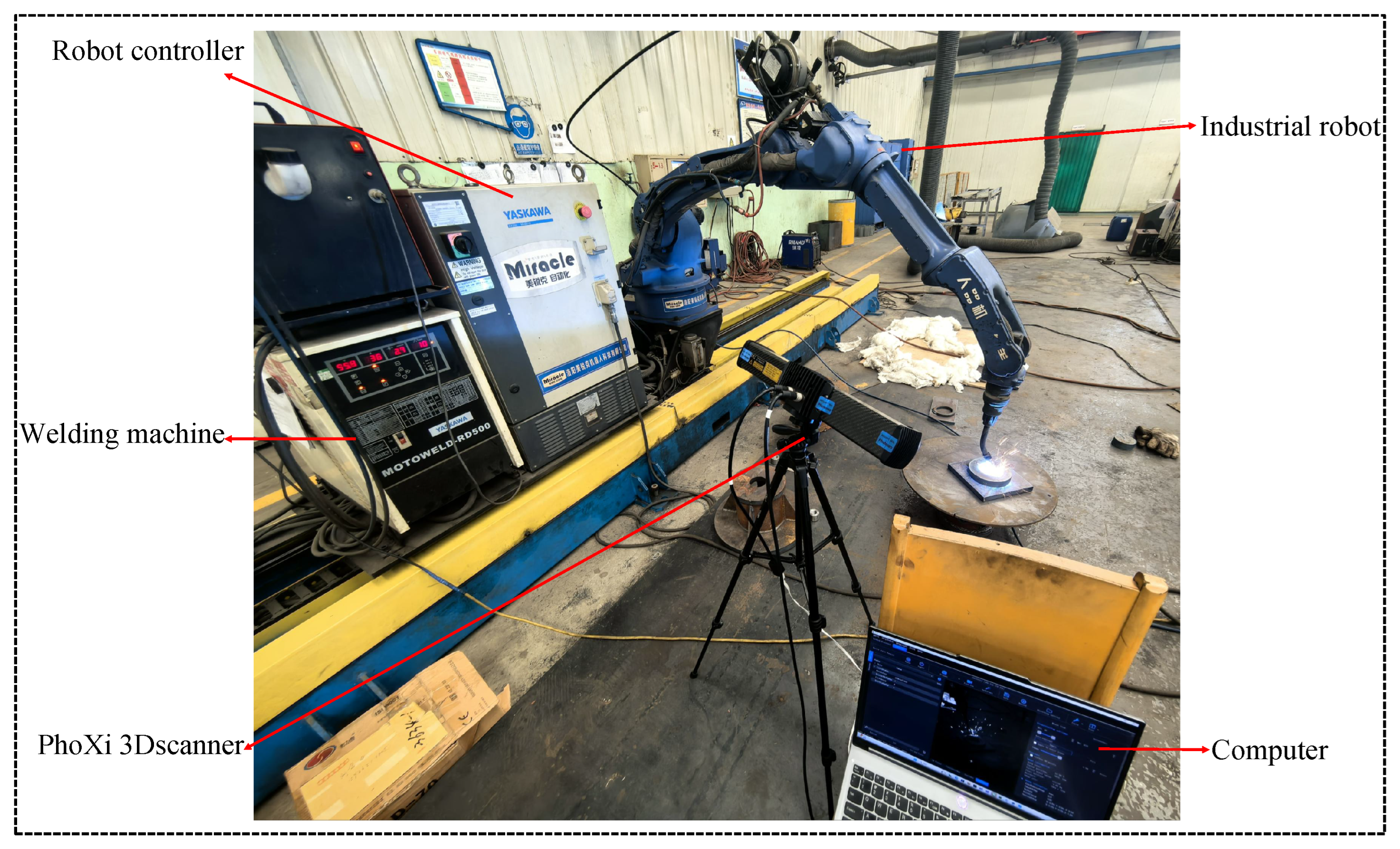
The experimental system was constructed on an integrated robotic welding workstation, as shown in Figure 6. The primary hardware components include a YASKAWA MOTOMAN-MA2010 (YASKAWA, Shanghai, China) six-axis industrial robot equipped with a robotic controller, a GMAW power source, and a welding torch. A Photoneo PhoXi 3D scanner (Model M; Photoneo, Bratislava, Slovakia) employing structured light technology was also utilized. A high-performance computer configured with an Intel Core i7-14650HX CPU and NVIDIA GeForce RTX 4060 GPU was employed to meet the demands of deep learning model training and real-time inference.
To comprehensively validate the method’s generalization capability, types of workpieces featuring annular closed-curve welds were used, as shown in Figure 7. These consisted of (i) a ring with an outer diameter of 125 mm, inner diameter of 90 mm, and height of 12 mm; (ii) a cylinder with a diameter of 90 mm and height of 50 mm; (iii) a hollow cylinder with an outer diameter of 100 mm, inner diameter of 95 mm, and height of 100 mm; and (iv) a disk with a diameter of 390 mm and height of 25 mm. All workpieces, along with the 16 mm-thick base plate, were fabricated from Q235 carbon structural steel.

3.2. Dataset Construction

Due to the current lack of publicly available multimodal datasets featuring welding scenarios with strong interference, a specialized dataset for weld seam semantic segmentation and trajectory extraction was independently constructed to meet the requirements of this study. During data collection, welding parameters (current, voltage, and speed) and environmental interference intensity (arc light and fumes) were systematically controlled to ensure the diversity and challenge of the dataset. Specifically, the GMAW process parameters were set as follows: the welding current was 190–210 A, the arc voltage was 24–26 V, the robot’s travel speed was 5–7 mm/s, and an 80% Ar + 20% CO 2 gas mixture was used as the shielding gas at a flow rate of 20 L/min. A total of 1200 synchronized image–point cloud pairs were collected, covering four typical annular workpiece geometries: rings, cylinders, hollow cylinders, and disks, with 300 pairs per category. The dataset was randomly split into training, validation, and test sets at a 7:2:1 ratio to ensure evaluation fairness and statistical validity.
For semantic annotation, this paper manually annotated all images at the pixel level using a fine polygon tool. The categories included “annular workpieces” (ring/cylinder/hollow cylinder/disk) and “medium-thick plate substrates,” generating high-precision semantic masks. For ground truth trajectory acquisition, each workpiece was scanned using a high-precision PhoXi 3D scanner under ideal conditions free from arc light and fume interference. This yielded sub-millimeter accuracy 3D models, from which the centerlines of inner and outer welds were extracted as the trajectory ground truth, with point cloud accuracy reaching 0.01 mm. To mitigate systematic errors from potential setup misalignments, a rigid registration was subsequently performed to finely align the experimental data with the ground truth model prior to error calculation.

3.3. Evaluation Indicators

To comprehensively and quantitatively evaluate the overall performance of the proposed method, three core metrics were employed: Maximum Error (ME), Root Mean Square Error (RMSE), and processing time. These metrics were chosen to assess the algorithm from three critical perspectives essential for robotic welding applications: worst-case trajectory deviation, overall reconstruction accuracy and stability, and computational efficiency for real-time deployment.
ME measures the greatest Euclidean distance between any point on the algorithm-reconstructed weld seam trajectory and its corresponding point on the ground truth trajectory. This metric directly reflects the deviation level under worst-case conditions, making it crucial for evaluating trajectory stability and safety. Its calculation formula is
M E = max i = 1 N P recon , i P gt , i ,
where P recon , i denotes a point on the reconstructed trajectory, while P gt , i represents the corresponding point on the ground truth trajectory. For two-dimensional planar trajectory evaluation, P is a two-dimensional coordinate vector ( x , y ) . For three-dimensional spatial trajectory evaluation, P is a three-dimensional coordinate vector ( x , y , z ) .
RMSE is the square root of the average of the squares of the Euclidean distances between reconstructed trajectory points and true trajectory points. RMSE is more sensitive to larger error values, thereby better reflecting the maximum deviation in a trajectory or the impact of outliers, and evaluating the smoothness and stability of the trajectory. Its formula is
RMSE = 1 N i = 1 N P recon , i P gt , i 2 .
Processing time records the total time consumed from inputting a single frame image and raw point cloud to the final output of a smooth weld seam trajectory. This metric evaluates the algorithm’s computational efficiency and whether it meets the real-time requirements of industrial automated welding scenarios. The unit is milliseconds (ms).

3.4. Implementation and Training Details

To ensure effective training and fair comparison of the proposed model, this section details the training settings and hyperparameter selection for each module. All experiments were conducted using the PyTorch2.0 framework on a workstation equipped with an NVIDIA RTX 4060 GPU.
A self-built multimodal dataset for circumferential seam welding was employed, comprising 1200 sets of synchronously acquired RGB images and corresponding 3D point cloud data. Images were uniformly resized to 640 × 640 resolution and standardized. Point cloud data underwent preprocessing via voxel grid downsampling (voxel size = 2 mm) to reduce computational complexity while preserving geometric features.
The entire model was trained in an end-to-end fashion, with all modules optimized jointly. The training process was driven by the total loss function ( L total ), as defined in Section 2.5, which combines the primary trajectory reconstruction loss ( L trajectory ) with the auxiliary loss from the WSEF module ( L WSEF ). The encoder backbone of the WSEF module (STDC-Seg network) was initialized using pretrained weights. For the overall training, the Adam optimizer was utilized with an initial learning rate of 0.001, and the learning rate was adjusted using a cosine annealing strategy. The model was trained for 300 epochs with a batch size of 16. Data augmentation included random rotation (±5°) and brightness/contrast perturbations to enhance the model’s robustness.
For the improved PointNet++ model in the LPCF module, the number of sampling points for Farthest Point Sampling (FPS) in each Set Abstraction layer was set to 1024, 256, and 64. The number of groups G in the Shuffle Attention module was set to 4, as this value was determined through preliminary experiments to provide the optimal balance between feature granularity and representation robustness.
For trajectory fitting, the order p of the Fourier series fitting was set to 2. This value is experimentally proven to effectively filter noise while preserving weld geometric details, avoiding overfitting or underfitting.

4. Results and Discussion

4.1. Comparison Experiments

To validate the advanced capabilities and robustness of the proposed multimodal fusion method in complex welding interference environments, this section conducts comprehensive qualitative and quantitative comparisons against mainstream 2D visual weld seam extraction methods and 3D point cloud segmentation techniques. Experiments were conducted in real-world scenarios featuring intense arc light and dense fumes, covering four typical annular workpieces: rings, cylinders, hollow cylinders, and disks. This comprehensive evaluation assesses the trajectory reconstruction accuracy of different methods across both 2D planes and 3D spaces, and concludes with a physical verification of the final weld appearance compared against a traditional teaching–playback baseline to demonstrate the method’s practical effectiveness.

4.1.1. Comparison of 2D Trajectory Reconstruction

To evaluate the performance of the WSEF module in this paper, a comparison was conducted with the traditional image edge detection algorithm Canny [31], the lightweight semantic segmentation network STDC-Seg [24], and NAF-Seg [32], which combines the image restoration network NAFNet with the semantic segmentation framework for comparison. All methods were tested on the self-built dataset and underwent identical post-processing workflows (edge point extraction and 2D fitting) to ensure fair comparison.
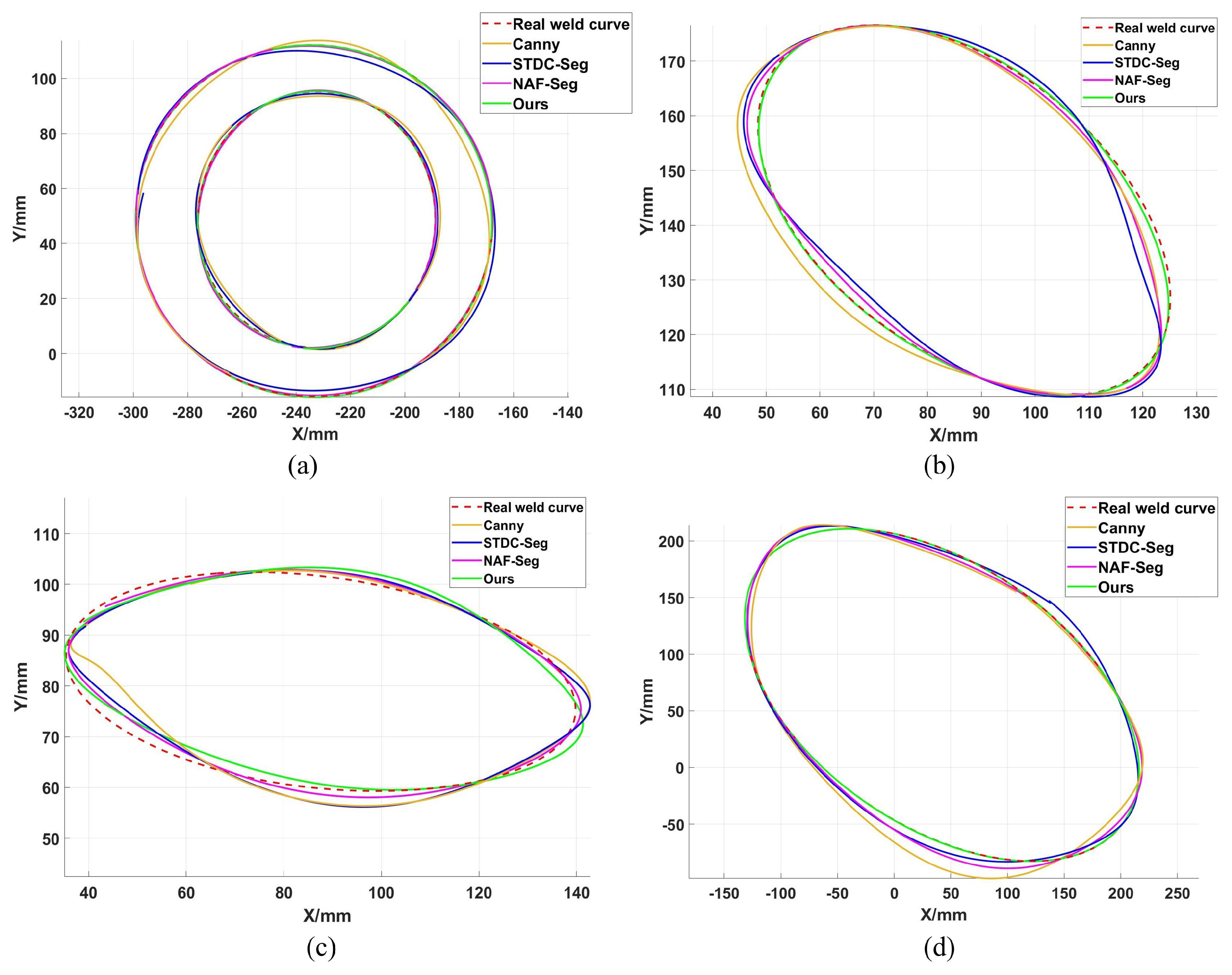
The four workpiece types used in the experiments are shown in Figure 8: ring (a), cylinder (b), hollow cylinder (c), and disk (d). To more intuitively demonstrate the 2D reconstruction performance of each method, Figure 9 compares the trajectory reconstruction results for these workpieces. The ground truth trajectory is indicated by a red dashed line in Figure 9 and serves as a reference for visual evaluation.
As shown in Figure 9, the traditional Canny operator nearly fails entirely in intense arc light regions, generating numerous false edges that cause reconstructed trajectories to deviate significantly or even break off. STDC-Seg demonstrates some interference resistance, but still exhibits noticeable contour shrinkage or deformation in the arc light core region, resulting in reduced trajectory accuracy. In comparison, NAF-Seg with its integrated denoising module performs better. However, its “denoising first, then segmentation” serial processing flow has information transmission loss, which limits its performance ceiling, and the accuracy in the overexposed core area is still insufficient. In contrast, the proposed method employs an end-to-end collaborative learning mechanism between arc light suppression and segmentation tasks. It explicitly perceives and restores features obscured by arc light contamination, achieving the highest alignment between reconstructed trajectories and actual weld profiles while demonstrating exceptional robustness.
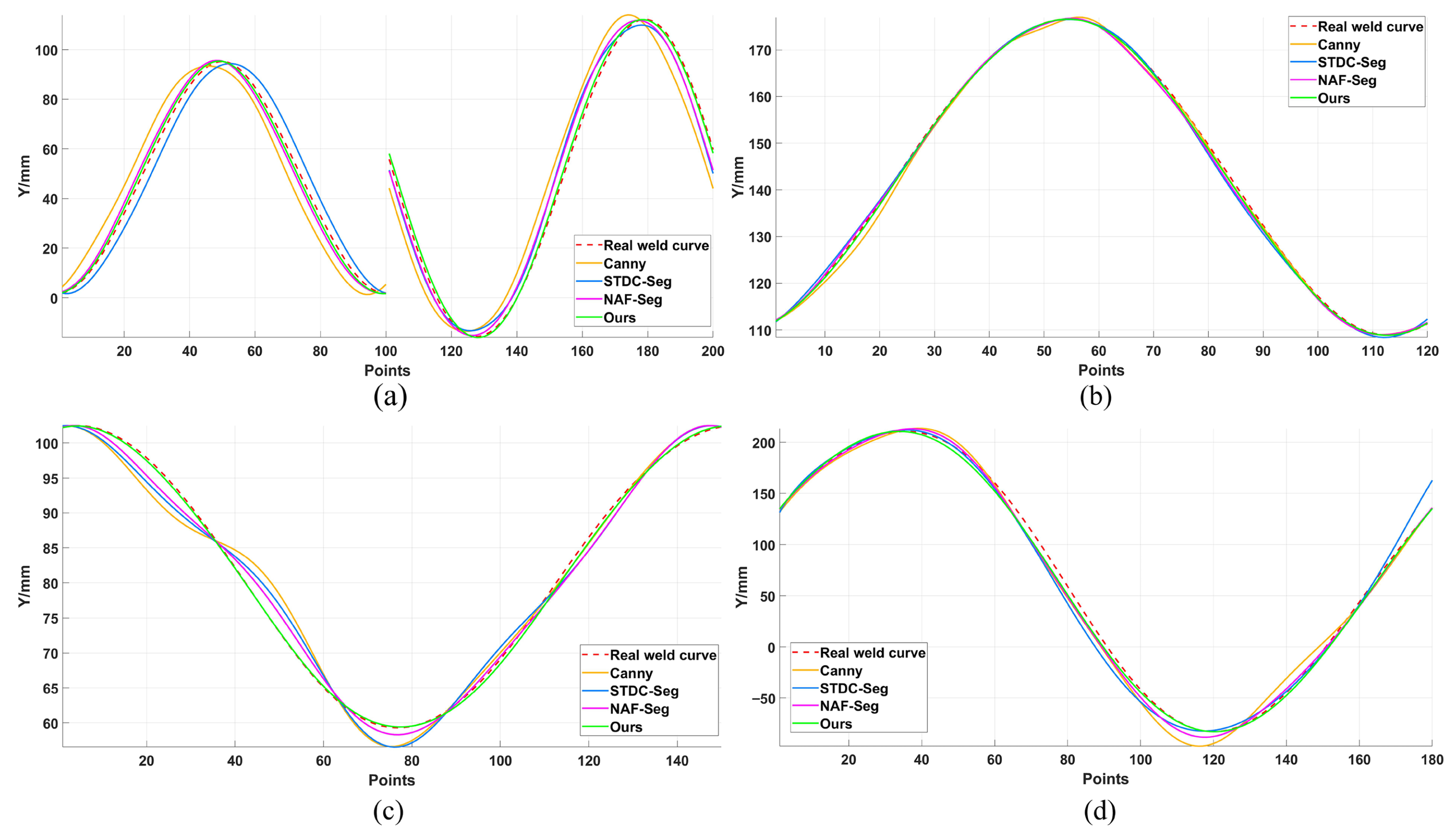
Figure 10 and Figure 11 show the point-by-point errors along the X-axis and Y-axis, respectively. These figures clearly demonstrate that the welding trajectory of the proposed method consistently and closely follows the actual trajectory with minimal fluctuations. Table 1 summarizes the detailed quantitative evaluation data, indicating that the proposed method achieves nearly the lowest ME and RMSE metrics across all workpieces. Particularly on the ring (a) workpiece, which suffers the most severe arc light interference, the proposed method achieves RMSE values as low as 0.56 mm and 0.54 mm for the X and Y axes, respectively. This represents an order-of-magnitude improvement in accuracy compared to the worst-performing Canny algorithm (RMSE of 6.56 mm and 4.56 mm). Even when compared to the relatively high-performing NAF-Seg algorithm, the proposed method reduced the X-axis RMSE on the ring (a) workpiece by 58.1% (from 1.34 mm to 0.56 mm), fully demonstrating the reliability and high precision of the proposed WSEF module under extreme interference conditions.

4.1.2. Comparison of 3D Trajectory Reconstruction

To comprehensively evaluate the overall performance of the proposed multimodal fusion framework in 3D trajectory reconstruction tasks, this paper compares it with several advanced benchmark methods. These include representative methods that directly process 3D point clouds, PointNet++ [26], KPConv [33], and SPFormer [34], which handle raw point clouds acquired under arc light and fume interference. Additionally, the multimodal fusion method PointPainting [28] is included, which integrates the 2D segmentation mask information generated by the WSEF module into the raw point cloud for processing. To ensure fairness in comparison, all contrasted algorithms ultimately undergo the identical trajectory reconstruction and smoothing post-processing workflow as described herein.
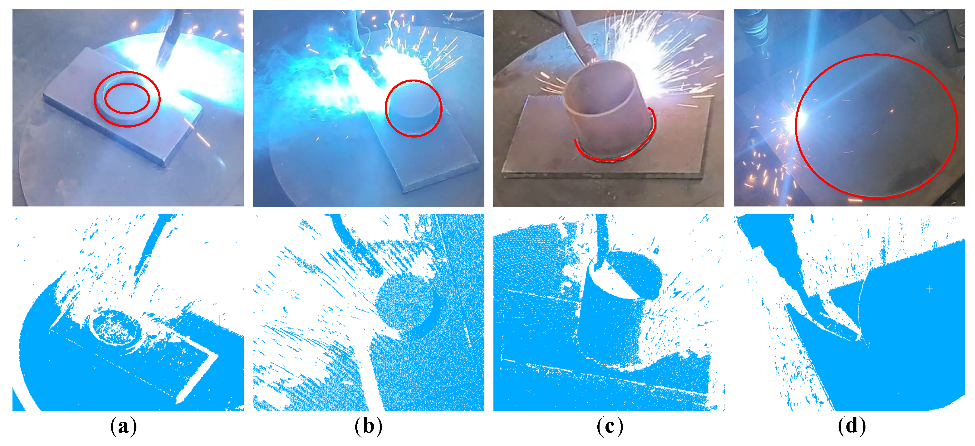
Figure 12 displays the raw data used for the 3D trajectory reconstruction comparison experiment. The top row shows the disturbed raw images, while the bottom row presents the synchronously captured raw 3D point clouds. The point cloud images clearly reveal that welding fumes generated a large number of outlier noise points, causing severe data loss and sparsity in critical weld seam regions.
Figure 13 visually shows the comparison between the 3D trajectories reconstructed by different methods and the true trajectories on four typical workpieces: a ring (a), a cylinder (b), a hollow cylinder (c), and a disk (d). It can be clearly observed from the figure that the PointNet++, KPConv, and SPFormer methods, which rely solely on 3D information, perform poorly in a strong interference environment.
Due to welding fumes causing extensive point cloud missing data, sparsity, and outlier noise, trajectories extracted by these unimodal methods exhibit significant deformation, distortion, or even discontinuity, deviating substantially from the actual weld path. In contrast, the PointPainting method, which integrates two-dimensional semantic information, demonstrates improved performance. Its reconstructed trajectories exhibit greater continuity and overall morphology closer to the true values, validating the effectiveness of multimodal information fusion. The proposed method achieves the best performance across all test cases, with reconstructed trajectories highly aligned with the true trajectory, featuring smooth morphology and the highest geometric accuracy.
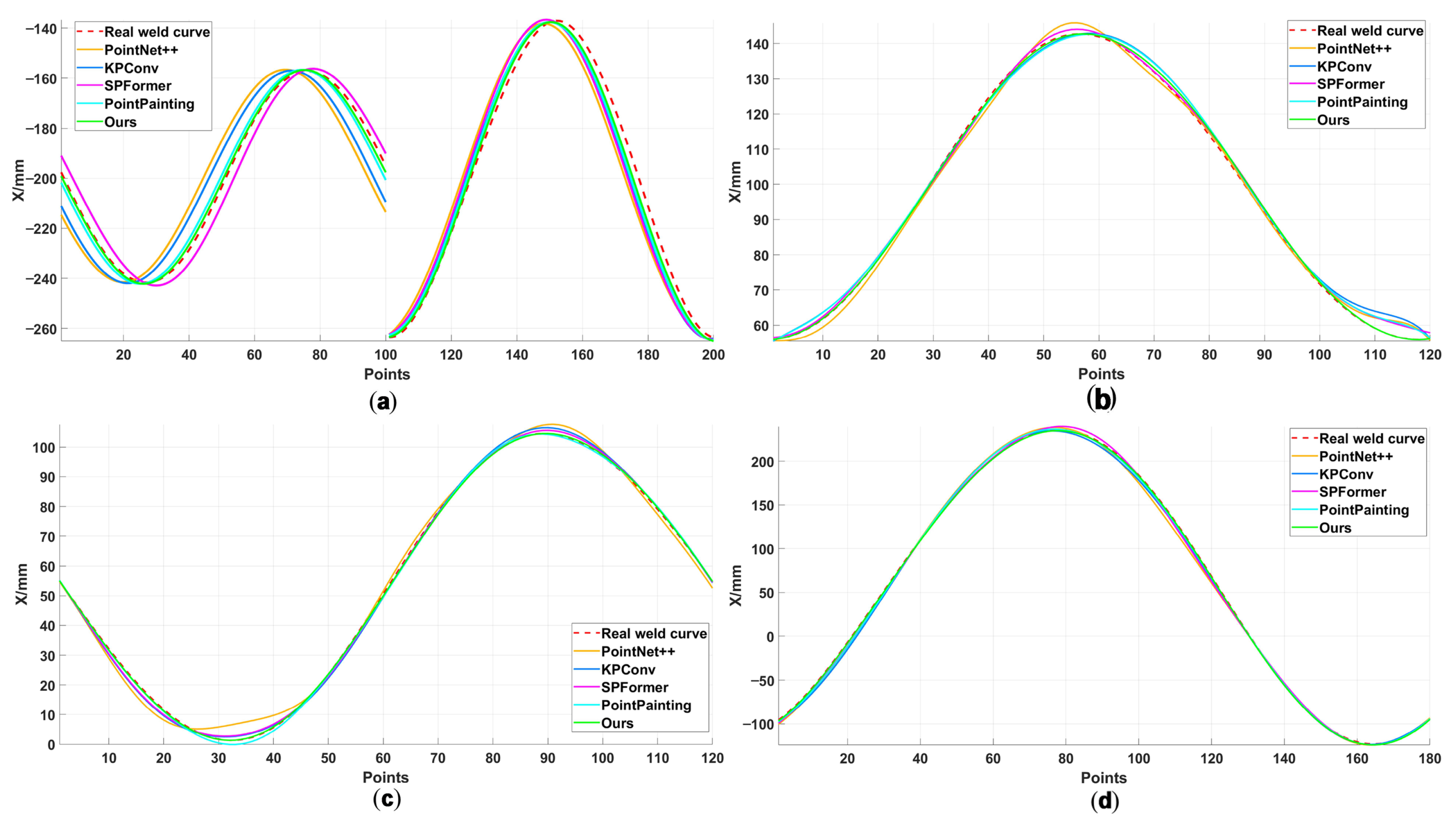
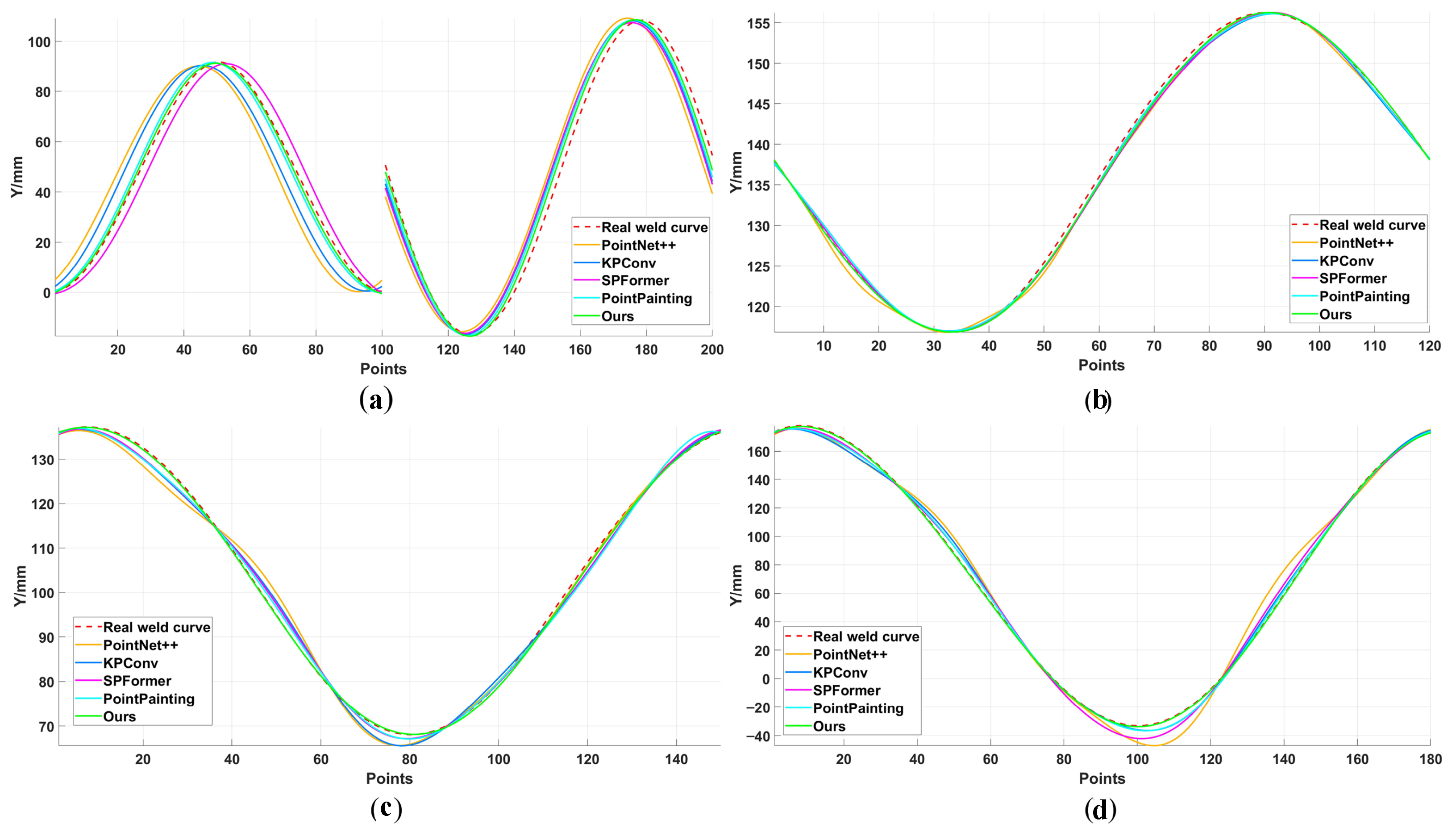
Figure 14, Figure 15 and Figure 16, which compare the coordinates of each axis, visually confirm that the reconstruction curves from the proposed method most closely adhere to the true trajectory. This finding is validated by the quantitative data in Table 2, which shows that the proposed method significantly outperforms all comparison methods in both ME and RMSE. For instance, on the most challenging workpiece, (a) ring, with severe point cloud degradation, the proposed method’s RMSE values are 0.57 mm, 0.59 mm, and 0.52 mm along the X, Y, and Z axes, respectively—a qualitative leap over PointNet++ (e.g., 6.12 mm on the X-axis) and a significant advantage over the multimodal PointPainting (e.g., 0.79 mm on the X-axis). This superior performance is attributed to the adaptive nature of the CMA module. An analysis confirmed that the network intelligently assigns higher importance to 2D features in overexposed regions while shifting its reliance to 3D features in areas obscured by fumes, demonstrating high precision and robustness in three-dimensional space.
In terms of computational efficiency, PointPainting exhibits the longest processing time due to its serial fusion pipeline, averaging over 5500 ms. The Transformer-based SPFormer model demonstrates higher computational complexity, with an average processing time approaching 5000 ms. This method benefits from an efficient parallel fusion framework, achieving an average processing time of approximately 4404 ms. This places it on par with PointNet++ and KPConv in terms of computational efficiency while significantly outperforming them in accuracy.
To further dissect the method’s robustness, a “stress test” was conducted on the challenging ring workpiece to evaluate the overall reconstruction error under fume-only, arc-only, and mixed interference conditions. The results, summarized in Table 3, confirm the proposed method’s superior robustness. While the unimodal PointNet++ is extremely vulnerable to fume interference (RMSE: 6.8208 mm) and the PointPainting fusion method maintains a stable but higher error (RMSE: 0.7–0.8 mm), the proposed method remains exceptionally stable across all conditions, with its overall RMSE consistently in the 0.53–0.55 mm range. This stress test confirms that the proposed fusion strategy is not only highly accurate but also significantly more robust to different and combined types of interference than competing methods, even on challenging geometries.

4.1.3. Physical Verification of Weld Quality

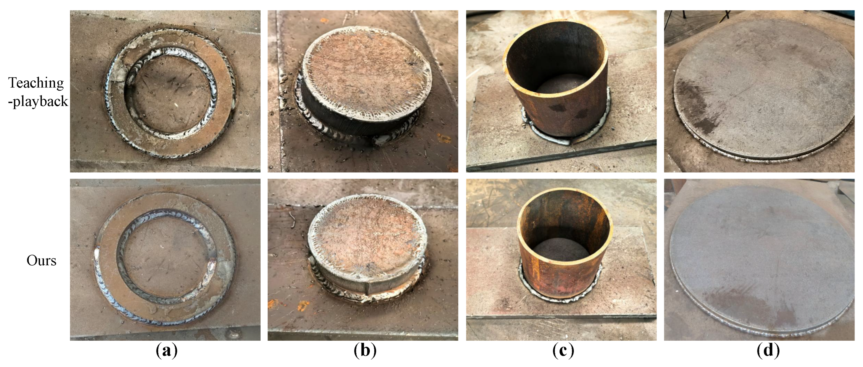
To provide physical verification of the proposed method’s practical effectiveness, a comparison of the final weld appearance was conducted against a traditional teaching–playback baseline. This manual baseline method is not only labor-intensive and extremely time-consuming, requiring point-by-point programming by a skilled operator, but its pre-programmed path also cannot adapt to thermal deformation during the GMAW process. In contrast, the proposed method automates trajectory generation, offering a significant reduction in setup time while providing real-time adaptation.
The visual results are presented in Figure 17. The welds produced by the teaching–playback method exhibit some minor imperfections, likely due to path deviations. In comparison, the weld beads resulting from the adaptive trajectory of the proposed method show improved smoothness and consistency. This physical evidence corroborates the numerical results, demonstrating that the high geometric accuracy of the extracted trajectory translates into a tangible improvement in final weld quality and process stability.

4.2. Ablation Experiments

To validate the effectiveness and necessity of each core module in the proposed multimodal fusion framework, a series of ablation experiments was designed. For this study, a baseline model was established, consisting of a basic multimodal framework that uses a standard STDC-Seg network for 2D segmentation, a standard PointNet++ network for 3D feature extraction, and a simple feature concatenation method for fusion. Building upon this baseline, the experiments sequentially introduced the proposed improvements—the SA mechanism in the LPCF module, the WSEF module, and the CMA mechanism in the MFF module—to quantitatively evaluate their respective impacts on 3D trajectory reconstruction accuracy.
The results, as summarized in Table 4, provide a clear analysis of each component’s impact on both accuracy and computational efficiency. The baseline model achieved an RMSE of 1.2298 mm with a processing time of 4557 ms, establishing the performance benchmark. The individual additions of the modules (Model A, B, and C) all improved accuracy, with the WSEF branch (Model C) providing the most significant gain by reducing the RMSE to 0.9493 mm. This highlights that mitigating image degradation is the most critical factor for accuracy. These individual additions, however, came with a slight increase in processing time, as expected due to the added computational steps.
A more interesting trend emerges from the module combinations. The combination of WSEF and SA (Model F) not only improved the RMSE to 0.6908 mm but was also slightly faster than the baseline at 4512 ms. This suggests that the 2D guidance from WSEF effectively filters the point cloud, reducing the computational load on the subsequent 3D modules, which compensates for the overhead of the SA mechanism. This efficiency gain is most prominent in the complete model (Ours). By incorporating all three innovations, the final model not only achieves the highest accuracy with an optimal RMSE of 0.5895 mm but is also the fastest configuration, with a processing time of 4415 ms. This non-obvious result strongly suggests that the initial investment in high-quality 2D feature processing and guidance creates a significant downstream efficiency benefit, allowing for a more complex and accurate model that runs faster than simpler versions.
In summary, this comprehensive study validates that all three innovations are essential, working synergistically to achieve state-of-the-art performance in both accuracy and computational efficiency.

5. Conclusions

This paper proposes a high-precision multimodal fusion method to address the challenge of extracting circular weld seams severely disrupted by arc light and fumes in the GMAW process. Through comprehensive comparative experiments, the following key conclusions were drawn:
  • The proposed method achieves high-precision trajectory extraction under severe interference, demonstrating an RMSE below 0.6 mm and an ME under 1.2 mm. Its processing time of under 5 s balances accuracy with computational efficiency.
  • Compared to 2D image-based approaches, the proposed method overcomes the failures of traditional algorithms and the deformations seen in deep learning models under intense arc light. Quantitatively, it reduced the X-axis RMSE by 58.1% on the most challenging workpiece compared to the advanced NAF-Seg method.
  • Compared to 3D point cloud-based approaches, the proposed method demonstrates clear superiority. It overcomes the trajectory distortions caused by fume interference that plague unimodal 3D methods and is more accurate and computationally efficient than other multimodal techniques like PointPainting.
Nevertheless, the study also identified the following limitations and corresponding directions for future work:
  • Limitations of the current work were identified. The method’s generalization to diverse geometries like non-circular or open curves has not yet been verified, as the current trajectory reconstruction module is optimized for annular shapes. Furthermore, the mask intersection strategy is best suited for single-pass welds. Finally, the processing time of 4.4 s requires optimization, with the primary bottlenecks being the 3D point cloud processing and trajectory reconstruction steps.
  • Future work will focus on extending the framework’s capabilities and performance. To handle more complex geometries, the system will be enhanced with more flexible trajectory reconstruction techniques, such as B-spline fitting for complex curves and graph-based ordering for open paths. To achieve real-time performance, key objectives include replacing the PointNet++ backbone with a more efficient architecture and employing model compression.
  • The ultimate goal is full system integration for industrial deployment. This involves deploying a lightweight system on dedicated edge computing hardware and integrating it into a closed-loop adaptive control system. Achieving this will require overcoming challenges in robot–computer communication, developing a robust control strategy, and implementing a reliable calibration maintenance strategy to ensure long-term stability.

Author Contributions

Conceptualization, L.C. and H.Z.; methodology, L.C.; software, H.Z.; validation, L.C. and H.Z.; formal analysis, L.C.; investigation, L.C.; resources, L.C.; data curation, H.Z.; writing—original draft preparation, L.C.; writing—review and editing, L.C. and H.Z.; supervision, L.C.; project administration, L.C.; funding acquisition, L.C. All authors have read and agreed to the published version of the manuscript.

Funding

This research was funded by the Zhongyuan Science and Technology Innovation Leadership Talent Programme (254200510043), the National Scientific and Technological Innovation Teams of Universities in Henan Province (25IRTSTHN018), and the Key Research and Development Project of Henan Province (241111110200).

Institutional Review Board Statement

Not applicable.

Informed Consent Statement

Not applicable.

Data Availability Statement

The data presented in this study are available on request from the corresponding author.

Acknowledgments

The authors acknowledge the editors and reviewers for their valuable comments and suggestions.

Conflicts of Interest

The authors declare no conflicts of interest.

Abbreviations

The following abbreviations are used in this manuscript:
CMACross-Modal Attention
CNNConvolutional Neural Network
DBSCANDensity-Based Spatial Clustering of Applications with Noise
FPSFarthest Point Sampling
GAPGlobal Average Pooling
GMAWGas Metal Arc Welding
GNGroup Normalization
LOBBLocal Oriented Bounding Boxes
LPCFLocal Point Cloud Feature Extraction
MEMaximum Error
MFFMultimodal Feature Fusion
MLPMulti-Layer Perceptron
MSEMean Squared Error
PCAPrincipal Component Analysis
ReLURectified Linear Unit
RMSERoot Mean Square Error
RPNRegion Proposal Network
SAShuffle Attention
WSEFWeld Seam Edge Feature extraction

References

  1. Evans, L.M.; Sözümert, E.; Keenan, B.E.; Wood, C.E.; du Plessis, A. A review of image-based simulation applications in high-value manufacturing. Arch. Comput. Methods Eng. 2023, 30, 1495–1552. [Google Scholar] [CrossRef]
  2. Wang, X.; Xie, Z.; Zhou, X.; Gao, J.; Li, F.; Gu, X. Adaptive path planning for the gantry welding robot system. J. Manuf. Processes 2022, 81, 386–395. [Google Scholar] [CrossRef]
  3. Zheng, C.; An, Y.; Wang, Z.; Wu, H.; Qin, X.; Eynard, B.; Zhang, Y. Hybrid offline programming method for robotic welding systems. Robot. Comput.-Integr. Manuf. 2022, 73, 102238. [Google Scholar] [CrossRef]
  4. Zou, Y.; Zhan, R. Research on 3D curved weld seam trajectory position and orientation detection method. Opt. Lasers Eng. 2023, 162, 107435. [Google Scholar] [CrossRef]
  5. Wang, Z.; Li, L.; Chen, H.; Wu, X.; Dong, Y.; Tian, J.; Zhang, Q. Penetration recognition based on machine learning in arc welding: A review. Int. J. Adv. Manuf. Technol. 2023, 125, 3899–3923. [Google Scholar] [CrossRef]
  6. Peng, G.; Chang, B.; Wang, G.; Gao, Y.; Hou, R.; Wang, S.; Du, D. Vision sensing and feedback control of weld penetration in helium arc welding process. J. Manuf. Processes 2021, 72, 168–178. [Google Scholar] [CrossRef]
  7. Cheng, S.; Yi, Y.; Jiao, W.; Zhao, Y.; Yu, R. The super-resolution reconstruction of welding images based on semi-tensor product space channel dual aggregation. J. Manuf. Processes 2025, 152, 692–710. [Google Scholar] [CrossRef]
  8. Naji, O.A.A.M.; Shah, H.N.M.; Anwar, N.S.N.; Johan, N.F. Square groove detection based on Förstner with Canny edge operator using laser vision sensor. Int. J. Adv. Manuf. Technol. 2023, 125, 2885–2894. [Google Scholar] [CrossRef]
  9. Li, J.; Li, B.; Dong, L.; Wang, X.; Tian, M. Weld seam identification and tracking of inspection robot based on deep learning network. Drones 2022, 6, 216. [Google Scholar] [CrossRef]
  10. He, Y.; Cai, R.; Dai, F.; Yu, Z.; Deng, Y.; Deng, J.; Wang, Z.; Ma, G.; Zhong, W. A unified framework based on semantic segmentation for extraction of weld seam profiles with typical joints. J. Manuf. Processes 2024, 131, 2275–2287. [Google Scholar] [CrossRef]
  11. Kang, S.; Qiang, H.; Yang, J.; Liu, K.; Qian, W.; Li, W.; Pan, Y. Research on a Feature Point Detection Algorithm for Weld Images Based on Deep Learning. Electronics 2024, 13, 4117. [Google Scholar] [CrossRef]
  12. He, D.; Ma, R.; Jin, Z.; Ren, R.; He, S.; Xiang, Z.; Chen, Y.; Xiang, W. Welding quality detection of metro train body based on ABC mask R-CNN. Measurement 2023, 216, 112969. [Google Scholar] [CrossRef]
  13. Ye, J.; Yao, X.; Ran, G.; Ou, S. Initial point positioning of weld seam and robot pose estimation based on binocular vision. Meas. Sci. Technol. 2024, 35, 116201. [Google Scholar] [CrossRef]
  14. Wen, R.; Xie, W.; Fan, Y.; Shen, L. SABE-YOLO: Structure-Aware and Boundary-Enhanced YOLO for Weld Seam Instance Segmentation. J. Imaging 2025, 11, 262. [Google Scholar] [CrossRef]
  15. Zhang, Y.; Geng, Y.; Tian, X.; Zheng, F.; Jiang, Y.; Lai, M. A feature extraction approach over workpiece point clouds for robotic welding. IEEE Trans. Autom. Sci. Eng. 2024, 22, 75–84. [Google Scholar] [CrossRef]
  16. Fang, W.; Xu, X.; Tian, X. A vision-based method for narrow weld trajectory recognition of arc welding robots. Int. J. Adv. Manuf. Technol. 2022, 121, 8039–8050. [Google Scholar] [CrossRef]
  17. Wang, H.; Rong, Y.; Xu, J.; Xiang, S.; Peng, Y.; Huang, Y. WeldNet: A voxel-based deep learning network for point cloud annular weld seam detection. Sci. China Technol. Sci. 2024, 67, 1215–1225. [Google Scholar] [CrossRef]
  18. Kim, J.; Lee, J.; Chung, M.; Shin, Y.G. Multiple weld seam extraction from RGB-depth images for automatic robotic welding via point cloud registration. Multimed. Tools Appl. 2021, 80, 9703–9719. [Google Scholar] [CrossRef]
  19. Zhao, L.; Zhou, H.; Zhu, X.; Song, X.; Li, H.; Tao, W. Lif-seg: Lidar and camera image fusion for 3d lidar semantic segmentation. IEEE Trans. Multimed. 2023, 26, 1158–1168. [Google Scholar] [CrossRef]
  20. Cui, Y.; Chen, R.; Chu, W.; Chen, L.; Tian, D.; Li, Y.; Cao, D. Deep learning for image and point cloud fusion in autonomous driving: A review. IEEE Trans. Intell. Transp. Syst. 2021, 23, 722–739. [Google Scholar] [CrossRef]
  21. Zhang, Y.; Geng, Y.; Tian, X.; Sun, Y.; Xu, X. A novel weld seam extraction method with semantic segmentation and point cloud feature for irregular structure workpieces. Robot. Comput.-Integr. Manuf. 2025, 95, 102987. [Google Scholar] [CrossRef]
  22. Wu, P.; Gan, Y.; Dai, X. The weld extraction algorithm for robotic arc welding based on 3D laser sensor. In Proceedings of the 2019 Chinese Control And Decision Conference (CCDC), Nanchang, China, 3–5 June 2019; pp. 998–1002. [Google Scholar]
  23. Jiang, Q.; Wang, Y.; Kong, Y.; Liu, Y.; Ma, C. A monitoring network SIMNet for weld penetration status based on multimodal fusion. Sci. Rep. 2025, 15, 23355. [Google Scholar] [CrossRef]
  24. Fan, M.; Lai, S.; Huang, J.; Wei, X.; Chai, Z.; Luo, J.; Wei, X. Rethinking bisenet for real-time semantic segmentation. In Proceedings of the IEEE/CVF Conference on Computer Vision and Pattern Recognition, Nashville, TN, USA, 19–25 June 2021; pp. 9716–9725. [Google Scholar]
  25. Li, B.; Peng, X.; Wang, Z.; Xu, J.; Feng, D. Aod-net: All-in-one dehazing network. In Proceedings of the IEEE International Conference on Computer Vision, Venice, Italy, 22–29 October 2017; pp. 4770–4778. [Google Scholar]
  26. Qi, C.R.; Yi, L.; Su, H.; Guibas, L.J. Pointnet++: Deep hierarchical feature learning on point sets in a metric space. In Proceedings of the NIPS’17: Proceedings of the 31st International Conference on Neural Information Processing Systems, Long Beach, CA, USA, 4–9 December 2017; Volume 30. [Google Scholar]
  27. Zhang, Q.L.; Yang, Y.B. Sa-net: Shuffle attention for deep convolutional neural networks. In Proceedings of the ICASSP 2021—2021 IEEE International Conference on Acoustics, Speech and Signal Processing (ICASSP), Toronto, ON, Canada, 6–11 June 2021; pp. 2235–2239. [Google Scholar]
  28. Vora, S.; Lang, A.H.; Helou, B.; Beijbom, O. Pointpainting: Sequential fusion for 3d object detection. In Proceedings of the IEEE/CVF Conference on Computer Vision and Pattern Recognition, Seattle, WA, USA, 13–19 June 2020; pp. 4604–4612. [Google Scholar]
  29. Wu, R.M.; Zhang, Z.; Yan, W.; Fan, J.; Gou, J.; Liu, B.; Gide, E.; Soar, J.; Shen, B.; Fazal-e Hasan, S.; et al. A comparative analysis of the principal component analysis and entropy weight methods to establish the indexing measurement. PLoS ONE 2022, 17, e0262261. [Google Scholar] [CrossRef]
  30. Zhao, J.; Li, T.; Yang, T.; Zhao, L.; Huang, S. 2D laser SLAM with closed shape features: Fourier series parameterization and submap joining. IEEE Robot. Autom. Lett. 2021, 6, 1527–1534. [Google Scholar] [CrossRef]
  31. Canny, J. A computational approach to edge detection. IEEE Trans. Pattern Anal. Mach. Intell. 2009, PAMI-8, 679–698. [Google Scholar] [CrossRef]
  32. Chen, L.; Chu, X.; Zhang, X.; Sun, J. Simple baselines for image restoration. In Proceedings of the European Conference on Computer Vision, Tel Aviv, Israel, 23–27 October 2022; Springer: Cham, Switzerland, 2022; pp. 17–33. [Google Scholar]
  33. Thomas, H.; Qi, C.R.; Deschaud, J.E.; Marcotegui, B.; Goulette, F.; Guibas, L.J. Kpconv: Flexible and deformable convolution for point clouds. In Proceedings of the IEEE/CVF International Conference on Computer Vision, Seoul, Republic of Korea, 27 October–2 November 2019; pp. 6411–6420. [Google Scholar]
  34. Sun, J.; Qing, C.; Tan, J.; Xu, X. Superpoint transformer for 3d scene instance segmentation. In Proceedings of the AAAI Conference on Artificial Intelligence, Montréal, QC, Canada, 8–10 August 2023; Volume 37, pp. 2393–2401. [Google Scholar]
Figure 1. Challenges in weld seam extraction: (a) Image overexposure and blurring caused by intense arc light; (b) Visual information obstruction due to welding fumes; (c) Degraded quality of 3D point clouds under interference.
Jmmp 09 00350 g001
Figure 2. Overall network architecture diagram.
Jmmp 09 00350 g002
Figure 3. Network architecture of the WSEF module. The network generates high-precision segmentation masks by coupling an arc light suppression branch with a segmentation branch. The restored image and a confidence map from the suppression branch guide the segmentation task, enhancing its accuracy under strong interference.
Jmmp 09 00350 g003
Figure 4. The improved PointNet++ architecture within the LPCF module. The key enhancement is the integration of an SA module into the Set Abstraction layer. As detailed in the lower panel, the SA module adaptively weighs point features using parallel channel and spatial attention, improving the network’s robustness to noise and outliers.
Jmmp 09 00350 g004
Figure 5. Flowchart of the MFF module. The module spatially aligns 2D edge points ( P pixel ) with 3D point cloud features ( F 3 D ). A CMA mechanism then adaptively fuses these features by learning the optimal contribution from each modality to produce a robust fused point cloud ( P fused ).
Jmmp 09 00350 g005
Figure 6. Robot welding workstation.
Jmmp 09 00350 g006
Figure 7. The four types of physical workpieces used in the experiments.
Jmmp 09 00350 g007
Figure 8. Original workpiece image under a strong interference welding environment: (a) ring, (b) cylinder, (c) hollow cylinder, and (d) disk.
Jmmp 09 00350 g008
Figure 9. Comparison of 2D trajectory reconstruction results using different methods for the four workpiece types: (a) ring, (b) cylinder, (c) hollow cylinder, and (d) disk.
Jmmp 09 00350 g009
Figure 10. Comparison of X-axis coordinates for 2D trajectories reconstructed using different methods for the four workpiece types: (a) ring, (b) cylinder, (c) hollow cylinder, and (d) disk.
Jmmp 09 00350 g010
Figure 11. Comparison of Y-axis coordinates for 2D trajectories reconstructed using different methods for the four workpiece types: (a) ring, (b) cylinder, (c) hollow cylinder, and (d) disk.
Jmmp 09 00350 g011
Figure 12. Original point cloud and image of a typical workpiece in an arc light and fume environment for the four workpiece types: (a) ring, (b) cylinder, (c) hollow cylinder, and (d) disk.
Jmmp 09 00350 g012
Figure 13. Comparison of 3D trajectory reconstruction results among different methods for the four workpiece types: (a) ring, (b) cylinder, (c) hollow cylinder, and (d) disk.
Jmmp 09 00350 g013
Figure 14. Comparison of X-axis coordinates in 3D trajectory reconstruction using different methods for the four workpiece types: (a) ring, (b) cylinder, (c) hollow cylinder, and (d) disk.
Jmmp 09 00350 g014
Figure 15. Comparison of Y-axis coordinates in 3D trajectory reconstruction using different methods for the four workpiece types: (a) ring, (b) cylinder, (c) hollow cylinder, and (d) disk.
Jmmp 09 00350 g015
Figure 16. Comparison of Z-axis coordinates in 3D trajectory reconstruction using different methods for the four workpiece types: (a) ring, (b) cylinder, (c) hollow cylinder, and (d) disk.
Jmmp 09 00350 g016
Figure 17. Comparison of physical weld appearance on the four workpiece types: (a) ring, (b) cylinder, (c) hollow cylinder, and (d) disk.
Jmmp 09 00350 g017
Table 1. Error analysis of 2D trajectory reconstruction using different methods (optimal: bold).
MethodsX (mm)Y (mm)
MERMSEMERMSE
(a) RingCanny [31]13.34626.56429.13214.5563
STDC-Seg [24]5.68432.84522.65231.3214
NAF-Seg [32]2.46851.34272.26481.0863
Ours1.14540.56231.13460.5423
(b) CylinderCanny [31]6.35673.15422.56341.2653
STDC-Seg [24]4.36122.28231.34260.6237
NAF-Seg [32]1.86390.92160.74560.3237
Ours0.23150.10250.76340.3142
(c) Hollow CylinderCanny [31]6.05632.86322.70831.3462
STDC-Seg [24]3.12361.46512.63011.2657
NAF-Seg [32]2.95311.37432.08311.0423
Ours0.36210.17520.35470.1432
(d) DiskCanny [31]4.04231.962110.57145.0542
STDC-Seg [24]2.88631.43277.14283.4146
NAF-Seg [32]1.8320.86711.57140.7864
Ours1.06570.52591.14280.5946
Table 2. Error analysis of 3D trajectory reconstruction using different methods (optimal: bold).
MethodsX (mm)Y (mm)Z (mm)Time (ms)
MERMSEMERMSEMERMSE
(a) RingPointNet++ [26]12.31466.124510.24235.16312.36922.84344856
KPConv [33]9.32454.64618.14274.26341.54610.75234665
SPFormer [34]3.03211.52412.34211.25341.39230.70625012
PointPainting [28]1.58940.79391.26310.66351.23840.62815645
Ours1.18540.57141.16140.59121.03450.51614573
(b) CylinderPointNet++ [26]5.32162.53142.53241.26312.13461.06544656
KPConv [33]4.36942.34581.93460.95781.31360.65844245
SPFormer [34]3.25631.68541.46330.75611.51310.76164783
PointPainting [28]1.74120.89241.03390.51651.19310.60615345
Ours0.83240.42510.99340.52240.92570.46234271
(c) Hollow CylinderPointNet++ [26]5.32462.53144.54362.27525.78942.86214716
KPConv [33]4.21342.13242.53871.25634.45782.36344405
SPFormer [34]2.52451.23692.32541.12624.21052.14364925
PointPainting [28]1.14790.52671.26540.63543.15781.56395427
Ours0.63240.32140.86320.42150.66310.33184353
(d) DiskPointNet++ [26]1.38320.694312.34656.23244.72432.34274793
KPConv [33]0.99580.53513.36451.62541.22340.61734502
SPFormer [34]1.11250.55516.23463.62641.65310.82314987
PointPainting [28]0.37390.18893.37811.66340.86210.43465587
Ours0.36310.18140.65460.34740.55210.23274418
Table 3. Performance analysis (overall error on ring workpiece) under different interference conditions (optimal: bold).
MethodsInterference ConditionME (mm)RMSE (mm)
PointNet++ [26]Fume-only (100% Fume, 0% Arc)13.67696.8208
Arc-only (0% Fume, 100% Arc)6.56093.2467
Mixed (50% Fume, 50% Arc)8.36214.2359
PointPainting [28]Fume-only (100% Fume, 0% Arc)1.38040.6929
Arc-only (0% Fume, 100% Arc)1.45080.7109
Mixed (50% Fume, 50% Arc)1.59320.7907
OursFume-only (100% Fume, 0% Arc)1.06650.5301
Arc-only (0% Fume, 100% Arc)1.08090.5399
Mixed (50% Fume, 50% Arc)1.14090.5508
Table 4. Ablation experiment results. (✓ indicates that the module was used; ✕ indicates that the module was not used.) (optimal: bold).
ModelWSEFSACMAME (mm)RMSE (mm)Time (ms)
Baseline2.48921.22984557
Model A2.09521.02094625
Model B1.98890.98564698
Model C1.89470.94934658
Model D1.47820.74454776
Model E1.42890.70984758
Model F1.38980.69084512
Ours1.17890.58954415
Disclaimer/Publisher’s Note: The statements, opinions and data contained in all publications are solely those of the individual author(s) and contributor(s) and not of MDPI and/or the editor(s). MDPI and/or the editor(s) disclaim responsibility for any injury to people or property resulting from any ideas, methods, instructions or products referred to in the content.