Article

Energy Efficient Jet Polishing via Electrolytic Plasma Enhances Corrosion Resistance in Stainless Steel

1
School of Biomedical and Precision Engineering, Bern University, 3010 Bern, Switzerland
2
School of Engineering and Computer Science, Bern University of Applied Science, 2501 Biel, Switzerland
3
Laboratory of Mechanics of Materials and Nanostructures, Empa—Swiss Federal Laboratories for Materials Science and Technology, 3602 Thun, Switzerland
*
Author to whom correspondence should be addressed.
J. Manuf. Mater. Process. 2024, 8(6), 289; https://doi.org/10.3390/jmmp8060289
Submission received: 29 October 2024 / Revised: 28 November 2024 / Accepted: 3 December 2024 / Published: 12 December 2024

Abstract

:
This study systematically compares the surface polishing performance and finishing results of the following two different electrolytic plasma polishing technologies on stainless steel AISI 316L: (i) plasma electrolytic polishing (PEP) and (ii) plasma electrolytic polishing jet (PEP-Jet). The two techniques are compared against an industrial standard polishing method, electropolishing (EP). For comparable energy density consumption, the samples treated with the PEP-Jet technique showed the highest removal rate, up to three times less than the initial roughness, resulting in the highest surface roughness reduction from Sa = 249 nm to Sa = 81 nm. Microstructure characterization of samples treated using PEP-Jet also showed well-defined crystalline grain boundaries with a distinct appearance of predominantly inter-crystalline structures within individual grains, which is uncommon with EP techniques. The surfaces treated using PEP-Jet exhibited the lowest corrosion rate of 6.79 × 10 5 mm/year, and no signs of areal corrosion were detected in the performed corrosion tests in contrast with the other samples and their respective treatments. The comparative analysis revealed that the high ionic current delivered by the electrolyte jet flow in the PEP-Jet process effectively stabilizes the plasma at the contact zone, thereby enhancing the plasma polishing of austenitic stainless steel samples. The efficacy of this method has been demonstrated in terms of reducing energy consumption and enhancing corrosion resistance in comparison with (PEP) and (EP) as state-of-the-art processes in corrosive environments of high-alloyed steel.

1. Introduction

Surface finishing techniques are essential for enhancing the surface properties of materials, resulting in improved functionality and performance [1]. These techniques aim to achieve desired surface characteristics, such as smoothness, glossiness, corrosion resistance, and chemical resistance [1]. Electrolytic polishing (EP) has become a popular method due to its ability to produce high-quality surfaces with improved mechanical properties and reduced surface defects [2]. However, traditional electrolytic polishing has limitations [1]. The process is conducted in large-scale bath systems, introducing challenges such as difficulty in achieving uniform polishing of complex geometries, which are commonly produced in precision engineering [3]; inefficient energy usage over extensive areas; and restricted control over localized polishing [4], which has led to the exploration of novel surface finishing techniques [5]. Plasma electrolytic polishing (PEP) is an innovative technique that has gained significant attention in recent years due to its capacity to achieve enhanced precision and surface quality through the utilization of plasma-assisted mechanisms to augment polishing efficiency [6,7]. PEP operates on the principles of electrochemical reactions and plasma discharges to achieve surface modifications [6]. In this process, electrochemical dissolution of the metal occurs, while the plasma discharges ionize the surrounding electrolyte, leading to localized physical metal dissolution as well as supporting the overall metal removal process [8]. In contrast to EP, PEP only uses environmentally friendly aqueous-based solutions and does not require any pre-cleaning step to remove greases or any other organic residues because of the plasma [9,10]. PEP technology holds significant potential for future improvements [11] since the different processes occurring within and close to the semi-stable vapor-gases envelope (VGE) [12] enclosing the metal surface are not yet completely understood [13,14]. PEP with an electrolyte jet (PEP-Jet) has emerged as a potential solution to further improve the polishing efficiency of PEP and even enable local polishing for selective surface treatments [7], as PEP is typically conducted in bath setups and thus applied uniformly across the entire workpiece [1,4,7,9]. Hence, PEP-Jet locally increases the removal rate, such that different polishings at specific regions for desired functionalities become feasible [3,15], allowing for different surface finishes and partial polishing of critical areas [16]. The jet also enables access to inner cavities and complex shapes that are otherwise difficult to polish in a PEP bath [17]. The use of an electrolyte flow leads to higher removal rates compared to the bath application [17]. This combination affords enhanced control over the material removal process, resulting in a superior surface finish with reduced waviness and roughness [7]. Electropolishing is a widely used surface finishing technique in many industries to enhance surface qualities such as roughness and corrosion resistance [2]. To evaluate its effectiveness, it is important to compare its results with those of PEP and PEP-Jet, considering the promising advancements in both technologies [6,18]. It is worth noting that studies combining EP with a jet—commonly known as, Jet-electropolishing (JEP) [19,20]—have been published [21]. Though interesting, the results are not explicitly integrated into this work, as the technique has not yet become an industrial standard.
The main aim of this study is to systematically compare the surface finishing outcomes of PEP, PEP-Jet, and EP polishing on austenitic stainless steel, which is widely used in many industries [22]. The study aims to evaluate the effectiveness of the three technologies in reducing surface roughness and improving corrosion resistance through experimental investigations and analytical assessments. The polishing limits of these technologies will also be examined [6]. The research findings will provide valuable insights into the capabilities of PEP and PEP-Jet, as well as their advantages [23] over traditional EP techniques, particularly in corrosive environments. Additionally, this study will contribute to the ongoing research efforts aimed at optimizing surface treatment processes.

2. Materials and Methods

This chapter addresses the preparation of materials, their characterization, electrolytic polishing techniques, and the polishing process by introducing the PEP and the PEP-Jet setups.

2.1. Sample Material and Preparation

The material utilized in this study is stainless steel 316L (X5CrNiMo17-12-2) (provided by Notz Metall AG, Brügg, Switzerland), a stainless austenitic alloy with a material composition of 17% chromium, 12% nickel, and 2% molybdenum. The stainless steel samples were subjected to annealing in a hydrogen atmosphere for a period of five minutes at a temperature of 1060 °C. This process was employed in order to reveal the austenite grain boundaries on the surface of the samples. The grooves that were induced at the junctions of these boundaries with the polished surface were the result of the annealing process [24]. Additionally, hydrogen is an effective reducing agent, particularly in high-temperature environments, which aids in producing clean surfaces. Furthermore, when metal parts are annealed in a hydrogen atmosphere, oxides and organic contaminants are eliminated, enhancing the reproducibility and quality of the resulting surface. Before the polishing process, each sample is subjected to a five-minute ultrasonic isopropanol bath to ensure cleanliness.

2.2. Material Characterization

Surface roughness measurements of all stainless steel samples before and after polishing were performed using an optical 3D profiler (Sensofar PLu neox, Barcelona, Spain).
The characterization of the surface and microstructure were also performed using a scanning electron microscope (SEM; TESCAN MIRA, Brno, Czech Republic) in the secondary electron (SE) detector mode.
Electrochemical corrosion rate analysis was performed using Metrohm Autolab PGSTATs (Metrohm AG, Herisau, Switzerland) in a 3.56 wt.% NaCl-containing solution. The conventional three-electrode system was implemented by using the Pt counter electrode (CE) and the Ag/AgCl reference electrode (RE). Prior to corrosion rate measurement, each sample was subjected to ultrasonic cleaning by using acetone and isopropanol lasting for 10 min, followed by DI-water rinsing. The potential dynamic polarization (PDP) technique was selected for corrosion rate analysis on a sample with a free surface diameter of 5 mm. First, open circuit potential (OCP) was determined for 10 min prior to corrosion measurement. PDP was conducted from −0.5 V to +1.1 V against the open circuit potential (OCP) with a constant scan rate at 0.1667 mV/s [25].

2.3. Electrolytic Polishing

To compare the polishing effectiveness of the three different techniques—EP, PEP, and PEP-Jet—the total electric energy input into the surface polishing was considered. EP was performed using a standardized electrolyte consisting of 50% phosphoric acid and 35% sulfuric acid. The electrolyte used for PEP electrolyte is composed of ammonium sulfate, in our case 10% of the latter [6,17]. The EP was performed at a voltage of 7 V for a process time of 15 min. The average measured current for all tests was 2.4 A, resulting in a total energy of 4.2 Wh. In order to achieve the same total energy per surface area of 518 mm 2 during polishing, PEP was performed in the bath for only 16 s by applying a constant voltage of 350 V resulting in an averaged direct current of about 2.7 A, equalizing the same energy density as for EP. For PEP-Jet, the jet was swept over a surface area of 15 × 15 mm 2 , which corresponds to the contact zone surface between the jet and the workpiece across the entire duration of the process. It is notable that the splash zone in the process is less clearly defined and involves additional parameters that are not investigated in this study. Consequently, the effectively polished surface area by the jet, which is approximately 25% larger than 15 × 15 mm 2 , is not taken into consideration, although that would render the jet-polishing even more energy-efficient. The electrolyte composition used is identical to that employed in the PEP bath. To replicate the EP electrical energy input into the polished surface, the required energy is 1.8 Wh. For the 2 mm jet diameter at a voltage of 350 V, a current of 0.4 A is required. To achieve the same energy per surface, each spot needs to be polished for 52 s. The jet velocity over the surfaces is calculated by considering the total polishing diameter of 5 mm since the polishing area is increased by the splash zone of the jet. This results in a required sweeping nozzle velocity of approximately 6 mm/min.

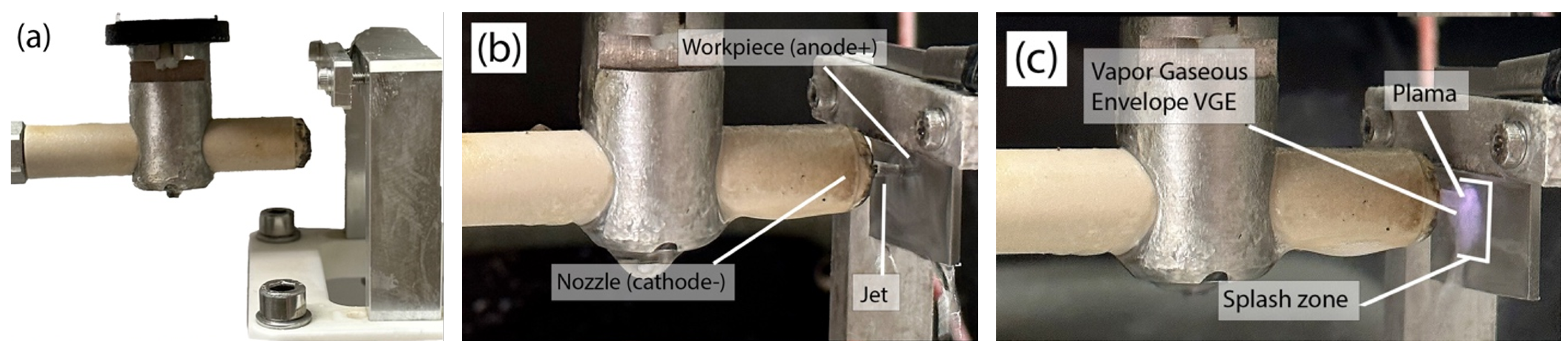
2.4. Polishing Process

The generic PEP process involves anodic polarization of the workpiece immersed in an aqueous electrolyte solution [26]. A significantly larger surface area is exhibited by the cathodic polarized tank [9] than the anodic workpiece, resulting in higher current density on the workpiece when a DC voltage is applied. Joule heating concentrates in the electrolyte at the workpiece surface, leading to the formation of a VGE and a subsequent dramatic increase in electrical resistance [27]. A sufficiently high supply voltage enables plasma ignition within the VGE, initiating PEP at the surface.
Electrochemical dissolution is considered significant during PEP because the electrolyte locally contacts the anodic surface when the plasma and its VGE break down [11,27]. Processes directly associated with the plasma, such as accelerated anions impacting the metal surface, contribute to surface polishing and generate the visible glow characteristic of PEP [6]. These anions cause the ejection of surface atoms—known as sputtering—upon impacting the metal surface. The material that is ejected is transferred to the VGE and then to the electrolyte [6]. This removed material is partially ionized and helps to maintain the discharge current. The surface roughness of the workpiece interacting with the plasma sheath results in a highly uneven electric field distribution, which leads to significant variations in discharge current density.
The PEP-Jet process (Figure 1) involves applying DC voltage between the cathodic nozzle and the anodic workpiece. The flow rate of the electrolyte jet in the PEP-Jet process is controlled by a combination of pump settings to ensure laminar flow [17], pressure regulators, and nozzle design. The pressure of the pump determines the velocity of the jet, while the geometry of the nozzle determines the focus and dispersion of the jet. A flow meter is used to accurately monitor and adjust the flow rate to ensure the formation of VGE. The electrolyte jet exiting the nozzle connects the workpiece with the nozzle, allowing an electrical current to flow (Figure 1c). The vapor gaseous envelope (VGE) forms inside the splash zone where the jet hits the metal workpiece. The shape of the polishing is determined by the size and shape of the nozzle [17].

3. Results

3.1. Energy Consumption

Table 1 shows the measured process voltage and current of PEP and PEP-Jet compared to the baseline experiments performed by EP. Thereby, all values represent the mean of three polished samples. PEP achieved a mean energy of 4.3 Wh, which is about 8% higher than the base targeted energy from EP. Due to the immersion into the electrolyte, the processing time is, on average, 17 s, which is longer than the calculated time of 16 s, resulting in higher energy consumption. The energy used to treat the surface with PEP-Jet was, on average 1.8 Wh. This is 3% less energy than that calculated to have the same energy per surface as EP. The reason for this is the lower process voltage, resulting in a lower power than expected.
Application-wise, PEP polishing for longer than about 20 s is relevant to achieve smooth finishing. As shown in Table 2, PEP polishing was also performed for longer periods of time in line with technically relevant surface levels.
The effectivity of PEP, PEP-Jet, and EP in reducing surface roughness was investigated. Figure 2 presents the optical macrographs results of EP, PEP, and PEP-Jet treatments on stainless steel samples with the same electrical input energy on the surface used for all three treatments. Figure 2a underwent electropolishing for 900 s, while Figure 2b was polished using plasma electrolytic polishing for 17 s, and Figure 2c using plasma electrolytic polishing with a jet for 52 s. The durations were chosen to ensure equal energy input into the surface across the three processes. Figure 3 shows images illustrating the polishing outcomes of PEP at various process durations that are closer to the applicable process times in reality. It is evident that the surface quality improves with extended exposure to the PEP process and this is proved by the results.

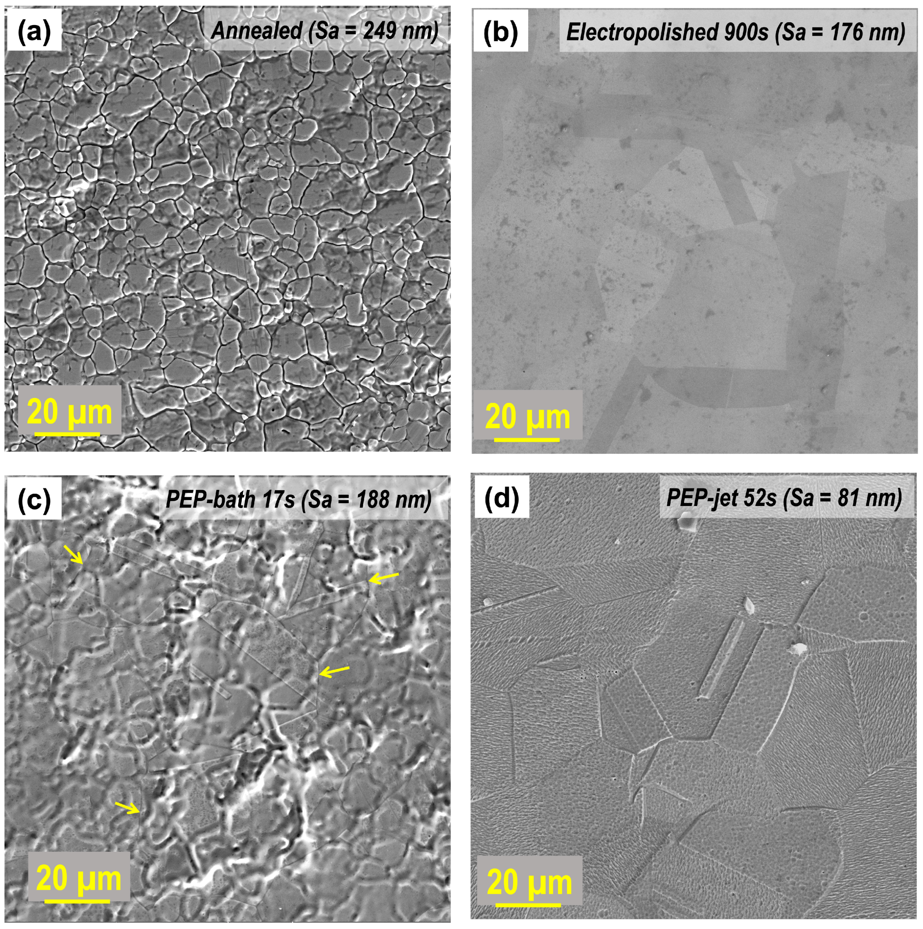
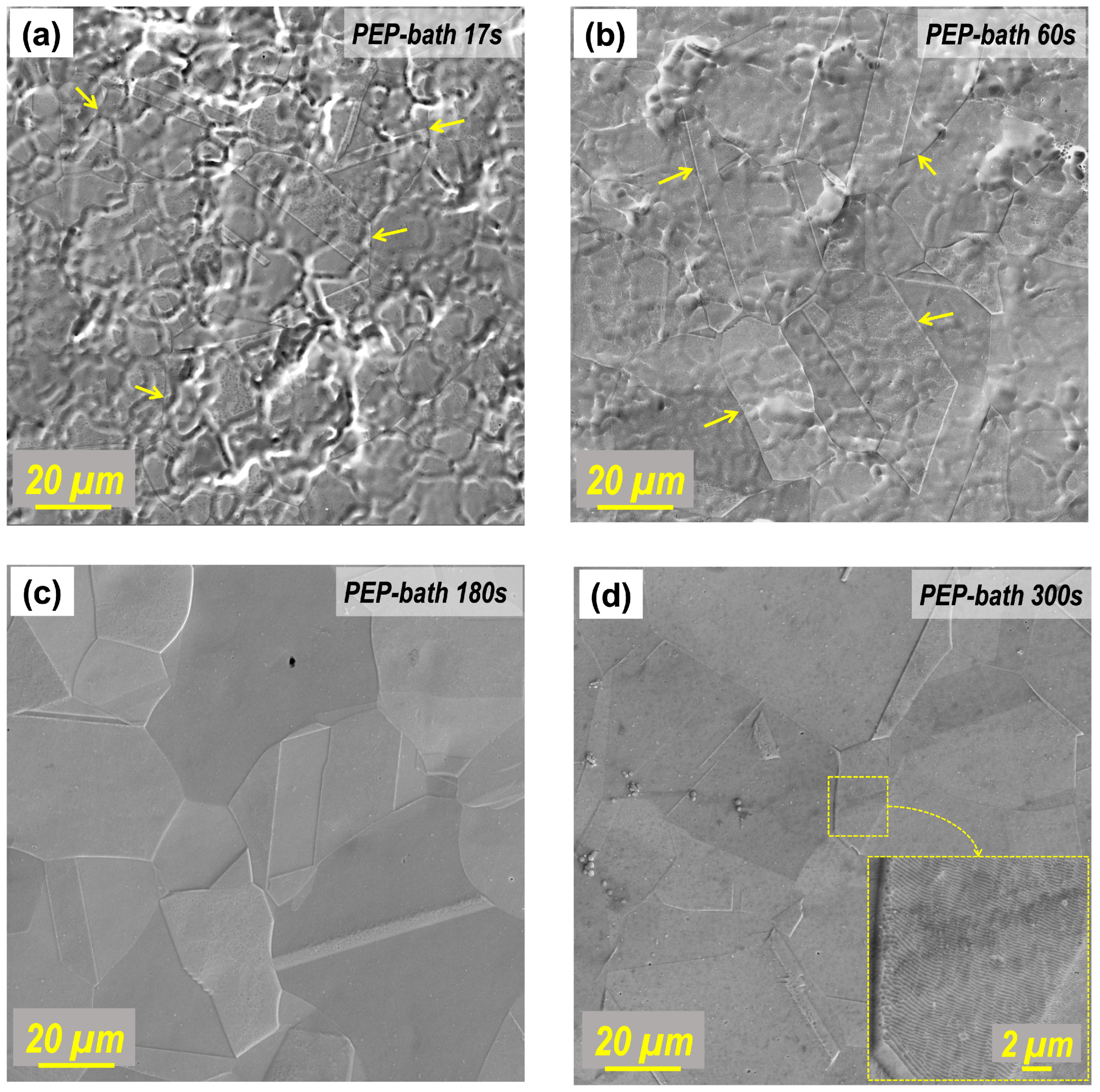
3.2. Characterization of Surface and Microstructure

Figure 4 illustrates both the annealed initial surface state and the surfaces after polishing with EP, PEP, and PEP-Jet, each exposed to an equivalent process energy per unit surface area. The initial surface roughness (Sa) measures 249 nm. After 17 s of PEP treatment, Sa decreased to 188 nm, while the EP process resulted in an Sa of 176 nm. PEP-Jet exhibited an Sa of 81 nm, revealing distinct grain boundaries and a notably flat surface compared to EP and PEP. The results suggest that PEP-Jet has a higher polishing rate than EP, requiring significantly less time. Surfaces polished with EP exhibited a smoother topography than those treated with an equivalent PEP energy input. The process duration for EP was over 50 times longer than that for PEP, indicating an optimum process time for EP of 15 min. However, PEP’s 17 s process time, as evident in Figure 5, appears to be insufficient for achieving the desired surface smoothness.
The roughness measurements obtained from 17 s of PEP are promising. However, it is evident that the same amount of energy input into PEP does not produce the same roughness and gloss effects as EP. To investigate the impact of extended process durations on the surface finish of samples, samples were polished for 1, 2, 3, 5, and 7 min, which reflect the optimal process times for the PEP method. The following section presents and interprets the results of the extended polishing sessions. Figure 5 shows a clear reduction in roughness over longer process durations, as confirmed by SEM images provided for annealed samples, as well as samples processed for 1, 3, and 5 min. The initial Sa of 249 nm decreases significantly to 105 nm in the first two minutes. At 3 min, the roughness reaches Sa 96 nm. Negligible changes were observed between the 3 min and 5 min process time. The final roughness measurement after 7 min of PEP resulted in an Sa value of 88 nm, indicating an optimal process time window of approximately 2–3 min.
Figure 6 displays the SE images of surface morphology for the annealed sample (Figure 6a) and the EP, PEP, and PEP-Jet polished samples (Figure 6b–d), revealing distinct topographical and microstructural variations. The SEM micrographs of the annealed sample exhibit a granular-like surface morphology, as depicted in Figure 5 and Figure 6a. A smooth surface with well-defined grain boundaries at the micrometer scale is visible when the surface is treated using conventional EP for 900 s (as shown in Figure 6b), revealing a crystalline structure. The evidence shows that the size of the granular-like structure observed in the annealed sample (Figure 6a) is much smaller than the grain size of the material detected in the EP sample (Figure 6b). This confirms that the granular-like structure is related to the topography of the stainless steel with its native oxide layer. The SEM micrograph in Figure 6c shows that a sample subjected to plasma electrolytic polishing in a bath electrolyte (PEP bath) for 17 s exhibits a diminished fraction and intensity of the granular structure in comparison to the annealed sample state. This observation can be attributed to the electrochemical effects associated with selective material removal, which is also confirmed by the significant decrease in Sa value to 188 nm. Additionally, visible grain boundaries begin to appear during this short PEP-bath process, as indicated by the yellow arrows in Figure 6c. The SEM micrograph in Figure 6d shows the microstructure of a heavily etched stainless steel sample treated with PEP-Jet. The surface roughness of this sample is the lowest (Sa = 81 nm) and is characterized by small, well-defined crystalline grains with a distinct appearance of predominantly intergranular cells within individual grains. Due to the random dissolution of crystallography planes, as can be seen in Figure 6d, surface brightening is also promoted [28]. Polishing may leave craters on treated surfaces (Figure 6d) due to discharge, indicating unstable plasma discharge conditions [29]. In addition, the intergranular cells are believed to be associated with the Mo-precipitate phase that is commonly observed in this type of material [30,31]. This is expected to enhance pitting corrosion resistance in particular [32,33].
The 316L stainless steel samples were also subjected to the extended PEP bath process to ensure optimum conditions for the surface polishing of these workpieces. Figure 7 shows SEM micrographs that demonstrate the effectiveness of the PEP-bath process in terms of surface finishing. Figure 7a shows the surface morphology after 17 s. The structure is non-homogeneous and non-uniform, with visible grain boundaries (indicated by yellow arrows in Figure 7a). After extending the PEP-bath process to 60 s (Figure 5), Figure 7b shows a combination of small, non-uniform granular structures with less distinct boundaries and larger grain sizes with well-defined boundaries. This transition morphology is interesting as it results in a lower surface roughness (Sa = 129 nm) compared to the previous 17 s PEP bath process. Figure 7c shows an SEM micrograph of a sample after 180 s (Figure 5) of PEP bath treatment where the granular structures with well-defined grain boundaries have completely disappeared. The surface morphology is smooth, with a roughness value of Sa = 96 nm. After 300 s of the PEP-bath process (Figure 5), the surface roughness decreases further to Sa = 95 nm, and the grain boundaries become sharper (Figure 7d) compared to the sample treated for 180 s. The SEM image at high magnification confirms the presence of intergranular cells within individual grains, as also observed in the PEP-Jet sample. This evidence suggests that the PEP-Jet surface quality can be achieved with more than 5 min of PEP-bath. The PEP process required a total energy of 60.3 Wh, compared to 4.9 Wh for PEP-Jet.

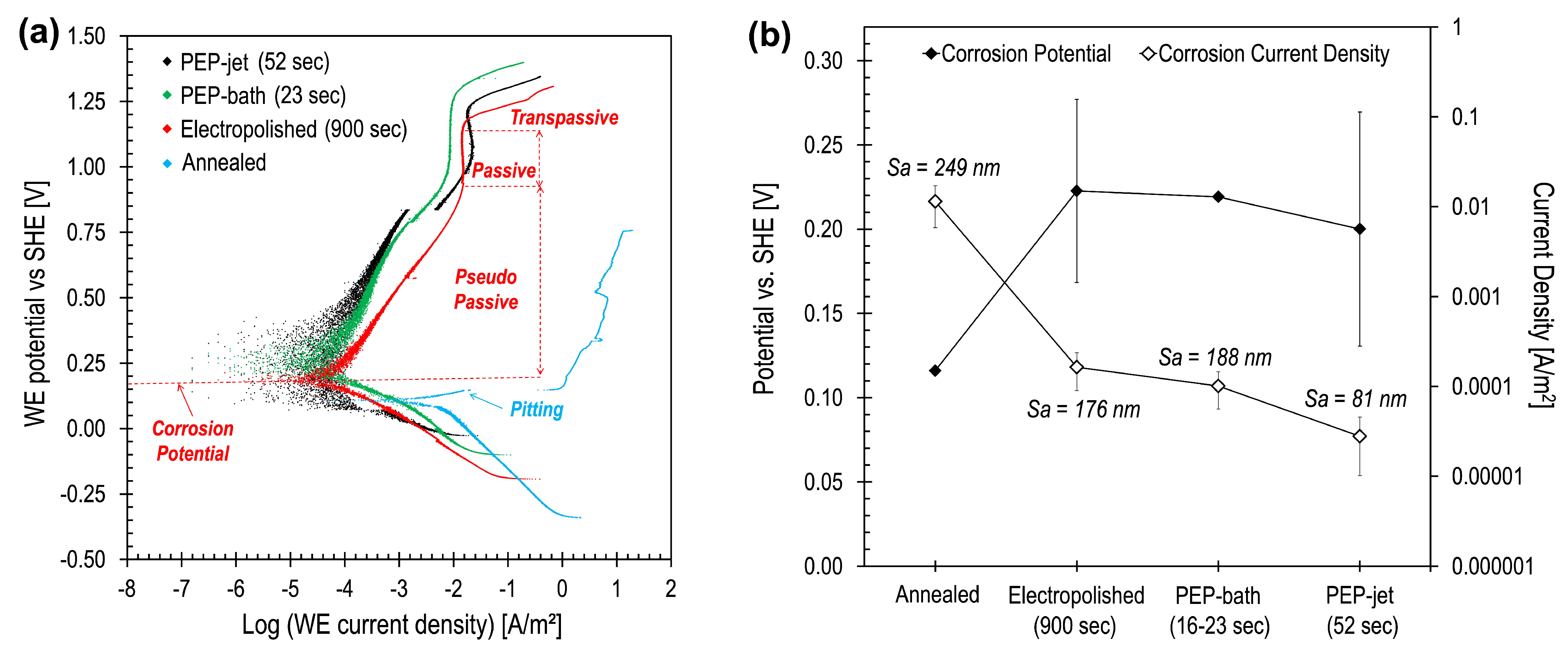
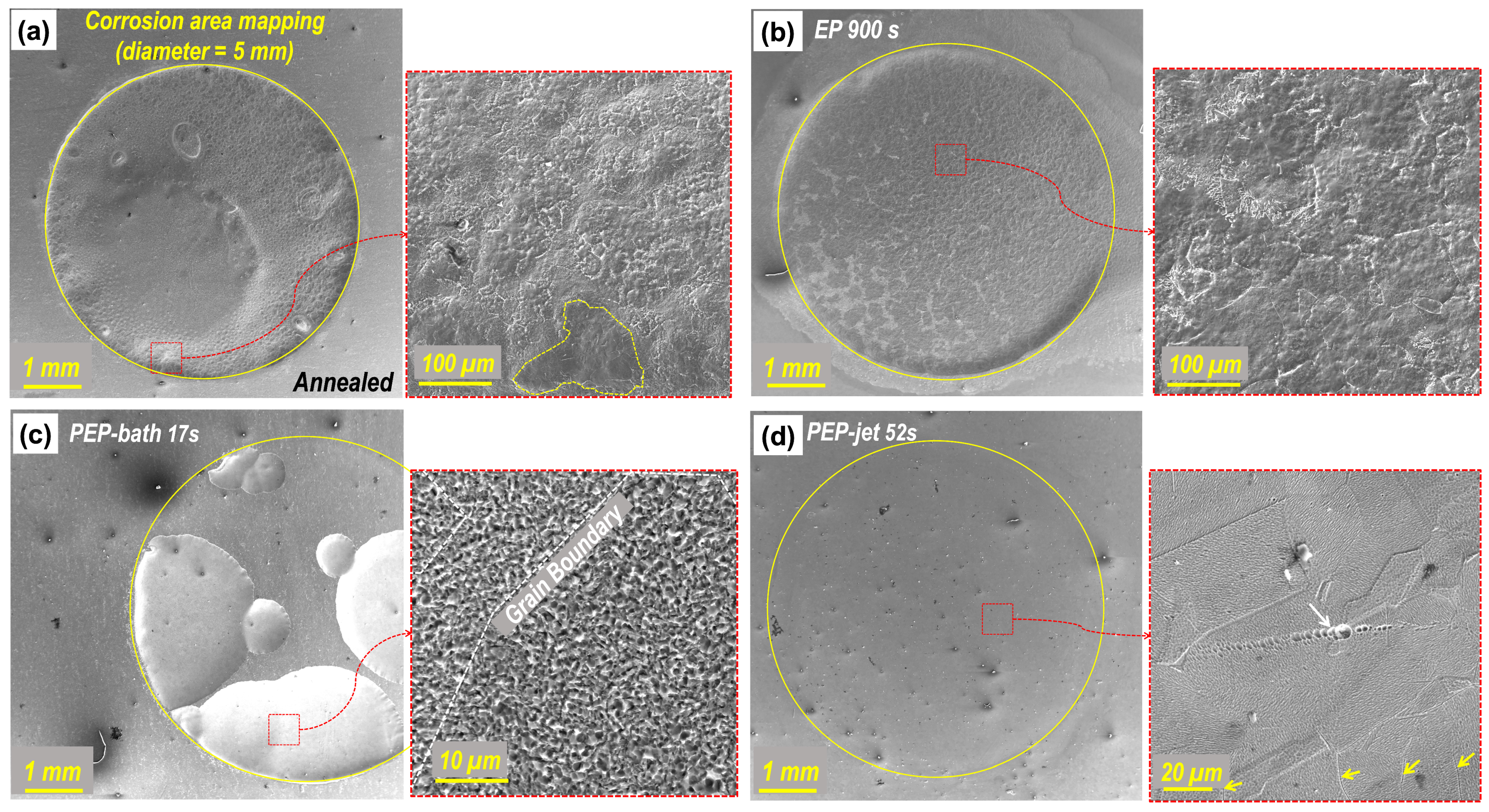
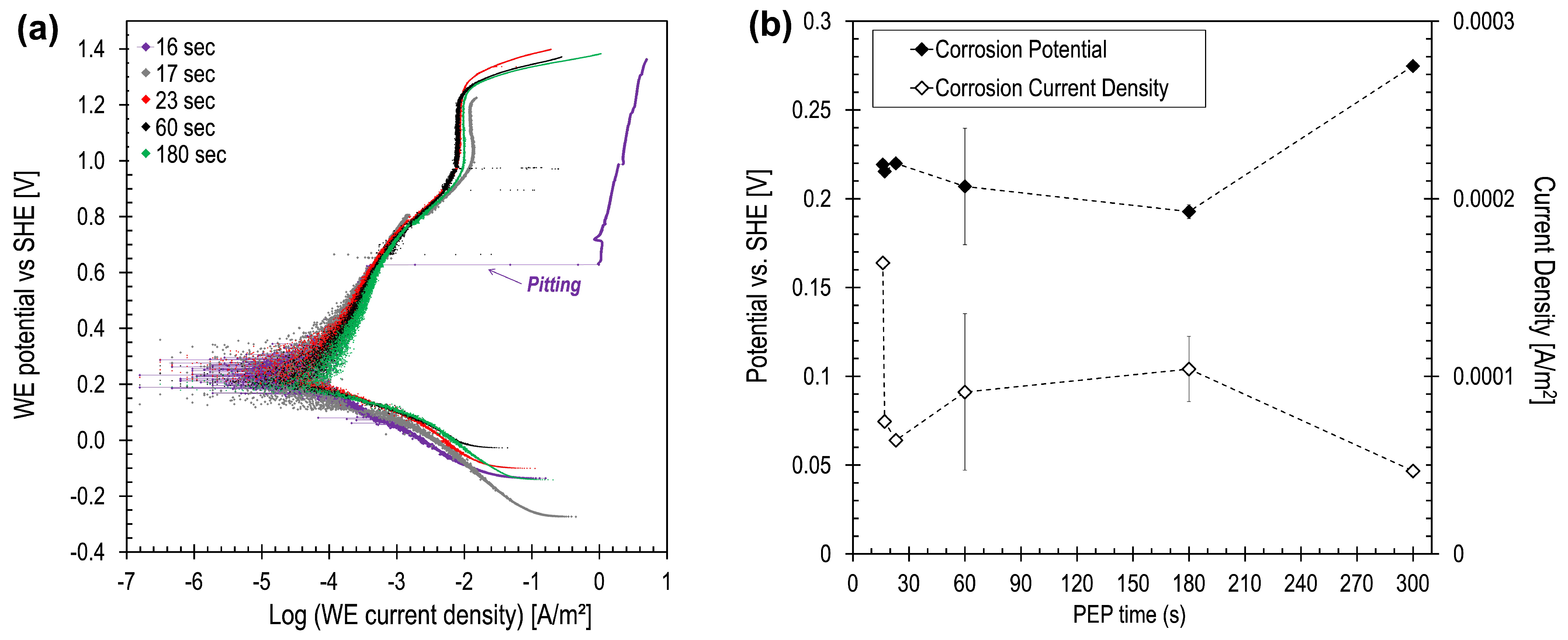
3.3. Corrosion Rate Analysis

Corrosion rate measurements were conducted using a dedicated corrosion rate analysis feature in Metrohm Autolab with NOVA software version 2.1.4. The formulation is based on anodic and cathodic Tafel analysis. The linear polarization technique was employed for annealed and differently polished samples to investigate the impact of surface finish on the corrosion resistance of stainless steel 316L. The typical anodic polarization curves are depicted in Figure 8a, while the calculated corrosion potentials and current densities are available in Figure 8b. For annealed samples, pitting corrosion is already observable even at the low potential and initial stage of the corrosion process, indicating imperfect and unstable passive film formations. In contrast, Figure 8a shows that all polished samples exhibit a wide range of pseudo-passive behavior from their corrosion potential and are completely passive at the later potential. In comparison with the annealed state, Figure 8b demonstrates that all polished samples exhibit significant enhancement of the corrosion potential and reduction of the corrosion current density (corrosion rate), indicating a more stable passive film formation and a higher corrosion resistance for polished samples. A sample treated using the PEP-Jet technique shows the lowest corrosion current density among the polished samples studied here, but they show similar corrosion potentials. It is also observed that the corrosion rate/current density also decreases with decrease in roughness value Sa of materials [34,35], which could be related to the total surface area involved for the corrosion process and the number of critical points affected in localized corrosion (e.g., pits formation and hydrogen evolution) [36,37].
The latter of the SEM micrographs (Figure 9) pertains to the surface corrosion tests conducted to compare the efficacy of the three distinct finishing techniques in enhancing surface quality and corrosion resistance. The images (Figure 9) reveal diverse responses to the corrosion tests among the treatments (i.e., anodic polarization to 1.0–1.1 V beyond the corresponding corrosion potentials). First, SEM images of annealed samples (Figure 9a) show a visible uniform corrosive effect with a circular boundary, indicative of pronounced corrosion, especially when compared with other surfaces. A high magnification image of this sample discloses a rather homogeneous corroded surface, resulting in an overall thinning of the surface of the sample. In addition, SEM images also observe the typical electrolytic polishing effect, resulting in the visible presence of grains and grain boundaries as indicated within the yellow dashed line in Figure 9a. These outcomes closely resemble the post-corrosion tests conducted on electrolytically polished samples (Figure 9b) that exhibit similar microstructures, particularly in the magnified image of Figure 9b. The image following the PEP treatment (Figure 9c) displays a distinct surface response. The observed specimen exhibited discernible corrosive effects, coupled with an increased resistance to corrosion. Nevertheless, under magnification (Figure 9c) of the corroded surface, an altered surface structure becomes apparent, marked by heightened roughness and the presence of irregularities like small pics. It is believed that this structure originates from the etching/corrosion of interior parts of grains due to an increase in polarization potential. The grain boundary paths are also recognizable as marked with the white dashed line in Figure 9c. This surface modification is totally different from the conventional corrosion effects observed in the initially annealed and EP-treated sample, but it exhibits microstructures that are identical to those in the sample subjected to the PEP-Jet approach (Figure 6d). On the other hand, post-corrosion SEM micrographs obtained for a PEP-Jet treated sample (Figure 9d) show a markedly smoother surface with no conspicuous signs of corrosion due to the test. The SEM magnified image within the corroded area shows only an exceptionally pristine surface with most of the grains and even grain boundaries slightly affected by the corrosion test, except for a few irregular corrosion spots, as marked with a white arrow, and the further etched and probably cracked grain boundaries, as indicated with the yellow arrows.
Corrosion rate analyses were also conducted for samples subjected to the PEP bath at different times. The typical anodic polarization curves for these samples are depicted in Figure 10a, while the calculated corrosion potentials and current densities are shown in Figure 10b. For this group of samples, pitting corrosion occurred only for a sample treated to the PEP bath stage for 16 s, as indicated in Figure 10a. The corrosion rate of this sample is also the highest among PEP-bath samples (see Figure 10b), indicating a less stable passive film compared to other PEP-bath samples. For the rest of the samples, it is hard to observe any significant influence of PEP-bath time on corrosion rate/current density since no visible trend was found from the samples used in this analysis. The grooves located along the grain boundaries of the bright annealed specimen are likely to be the initiation points for pitting corrosion. It is clear that surface roughness affects the corrosion properties [28].

4. Discussion

The electrochemical surface polishing technique known as PEP-Jet represents a significant advancement in the search for optimal surface finishing methodologies [17]. Previous studies on PEP, PEP-Jet, and EP [6,9] have demonstrated PEP-Jet’s superior polishing quality among these three methods [17], highlighting its enhanced polishing characteristics in terms of surface roughness.
This study demonstrates that the PEP-Jet approach is focused and localized, allowing for targeted surface treatment with a higher polishing rate [17]. This minimizes overall energy expenditure compared to broader, immersion-based methods such as PEP and conventional EP. Furthermore, the corrosion resistance results of the PEP-Jet-polished samples illustrate the improvement in stainless steel surface finishing regarding PEP and EP-bath methods. The surface roughness value of Sa = 81 nm resulted in the highest removal rate of up to 3.2 nm/s and a reduction in corrosion rate of up to 99.7% compared to the initially annealed surface sample. The polishing input with PEP and EP resulted in Sa values of 188 nm and 176 nm, respectively. Hence, the PEP-jet technique is positioned as an innovative and promising method for advanced surface finishing applications due to its ability to reduce energy consumption and process time while improving surface roughness and corrosion resistance. These findings contribute to the ongoing discourse on efficient and effective surface treatment methodologies, not only for stainless steel but also for other high-alloyed metals used in various demanding industrial applications.
The mechanism of PEP-Jet is of fundamental importance to the efficiency of this process. The electrolyte jet ensures a continuous flow of electrolytes to the surface of the workpiece, maintaining a high ionic current directed toward the plasma in the VGE. The electric field is effectively guided by the electrolyte jet, which has an estimated effective contact surface area of 12 mm 2 [17], with an ionic current density of up to 2.9 × 10 2 A/ mm 2 compared with 4.5 × 10 3 A/ mm 2 and 5.3 × 10 3 A/ mm 2 for the EP and PEP baths, respectively. This technique enhances the efficiency to about six times that of the polishing process by introducing a jet mechanism that facilitates the transportation of ions through the electrolyte. This is achieved by an electrolyte flow velocity of 500 mm/s towards the surface that is approximately ten times faster than the regular ion drift velocity in a PEP bath without any massflow [6]. The current drop across the electrolyte is more pronounced in the PEP-jet process due to the higher current density, which results in a greater current drop at constant conductivity. To address this challenge, it is essential to minimize the distance between the cathode (nozzle) and the anode (workpiece), also referred to as the working distance [38]. With the electrolyte massflow, the plasma is fed longer with the higher incoming flux of ions before it collapses locally. This also stabilizes the VGE locally in the center of the jet, which has the capacity to fully isolate the anodic workpiece surface from the electrolyte, effectively temporarily halting conventional electrolysis and thus keeping the plasma as long as there is sufficient current to feed it locally [39]. This favors pronounced plasma polishing-related activities in the center of the jet that interact more intensely with the stainless-steel grains and their boundaries. As illustrated in Figure 6d, an intergranular microstructure is evident, attributed to differential material removal rates between grains and their boundaries. This phenomenon is more prevalent in polycrystalline 316L due to its variable grain orientations and higher energy levels, which makes these regions more reactive. Zones influenced by plasma activity are often more susceptible to material removal [40] due to their intrinsic instability, which contrasts with the well-ordered crystal lattice within the grains. However, the intergranular polishing observed in Figure 6d suggests that physical, electrical, and thermal processes, driven by a quasi-stable plasma, play a significant role in the modification of the surface structure and corrosion properties of the stainless steel (316L) workpiece. The previously detailed findings are of significance with regard to potential applications where high surface quality standards are required. Additionally, PEP-Jet-finished samples exhibit superior corrosion resistance properties, with a rate of 6.79 × 10 5 mm/year compared with 2.73 × 10 4 mm/year for PEP, 3.74 × 10 4 mm/year for EP, and 2.63 × 10 2 mm/year for annealed samples.

Surface Quality and Corrosion Resistance

The correlation between corrosion rate and surface roughness in the samples is consistent with established principles of corrosion science. This relationship has been documented in numerous studies within the literature and aligns with the direct correlation between surface topography and corrosion resistance [36,41]. The phenomenon can be explained by considering several interrelated factors that govern the corrosion process on metal surfaces [36]. Surface irregularities and microstructures play a crucial role in initiating localized corrosion [42], as shown in Figure 6. Smoother surfaces have fewer irregularities, as seen in Figure 6d–Figure 7d, which reduces the number of potential nucleation sites for corrosion. This, in turn, mitigates the initiation and propagation of corrosion pits, resulting in a lower corrosion rate [43], as depicted in Figure 8.
The results indicate that the surface modification achieved by PEP-Jet involves polishing even into the grain structures (Figure 6d), making distinct intergrain microstructures visible. This phenomenon is well-established, even in prolonged PEP (Figure 7d), resulting in a reduction of Sa and a decrease in irregularities (Figure 4, Figure 6d and Figure 7d). This unique effect is a consequence of the combination of physical polishing effects and electrochemical processes that occur concurrently during the polishing. It is worth noting that, even with extended polishing times, this phenomenon is not observed in the case of EP (Figure 6b). The inter-crystalline structure, which is influenced by crystal orientation, becomes more pronounced during PEP-Jet treatment, leaving predominantly the less vulnerable crystal facets exposed on the surface [28]. The presence of active sites is one of the reasons corrosion occurs on alloys. In the case of stainless steel, these active sites are more prevalent on rough surfaces than on smooth surfaces because the protective oxide film does not form as effectively on rough surfaces [43]. Previous research indicates that the formation of pits is directly proportional to the availability of sites on rough surfaces. This study demonstrates that the formation of pits is dependent on surface roughness. This nuanced understanding of the surface alterations provides a comprehensive explanation for the superior corrosion resistance observed in tests [6]. Upon closer inspection of the corrosion test results, it can be observed that the specimens subjected to PEP-Jet treatment exhibit improved corrosion potentials and reduced leaking currents (Figure 8) compared with those treated with other techniques [44]. The correlation demonstrates the complex relationship between the inter-crystalline polished patterns induced by PEP-Jet and the resulting improvements in corrosion resistance, supporting the importance of this innovative surface treat- ment technology.

5. Conclusions

In this comprehensive study, plasma electrolytic polishing (PEP) and PEP-Jet were comparatively analyzed, while electropolishing (EP) was introduced as a state-of-the-art technology. Its inclusion serves primarily as a benchmark against which to evaluate the advancements and effectiveness of the more recent PEP and PEP-Jet techniques. The principal objective of this study was to examine the potential enhancements and distinctive advantages of PEP and PEP-Jet. The surface finishing effects of PEP, PEP-Jet, and EP on stainless steel 316L were systematically explored using precise roughness measurements, SEM analysis, and corrosion rate assessments. The obtained roughness data highlight the superior performance of PEP and PEP-Jet in reducing surface defects. PEP-Jet demonstrates the highest efficiency, achieving a remarkably low Sa value of 81 nm compared to PEP’s 188 nm with the same energy input. SEM analysis provided detailed insights into changes in crystalline grains, particularly intercrystalline polishing induced by physical polishing effects that are not apparent in electrochemical techniques. PEP-Jet, with its distinct microstructure characterized by well-defined crystalline grains and intergranular cells, thus exhibited enhanced resistance to pitting corrosion. All polished samples exhibited enhanced corrosion resistance compared with the annealed state. The lowest corrosion rate was 6.79 × 10 5 mm/year. The PEP-Jet processed sample exhibited superior resistance to corrosion, with a reduction in the corrosion rate of up to 99.7% compared with the annealed state. Further research into the interaction between the electrolyte jet dynamics, vapor–gas envelope formation, and the underlying microstructural changes could provide deeper insights into the optimization of surface roughness and corrosion resistance. Furthermore, the development of reliable models for current density distribution and plasma behavior in the contact and splash zones would enhance the precision of process control. The findings of this study contribute significantly to the existing body of knowledge, demonstrating the feasibility and advantages of the PEP-Jet process for localized and homogeneous surface treatments on 316L.
In summary, PEP technology can achieve higher corrosion resistance than EP on austenitic stainless steel. Additionally, PEP-Jet techniques demonstrate superior polishing efficiency compared with PEP and EP.

Author Contributions

Conceptualization, A.G. and K.P.; methodology, A.G. and K.P.; software, Y.S. and A.K.; validation, J.B., T.N. and C.B.; formal analysis, A.G. and K.P.; investigation, A.G. and K.P.; resources, C.B.; data curation, A.G., K.P. and Y.S.; writing—original draft preparation, A.G.; writing—review and editing, K.P., J.B., T.N. and C.B.; visualization, T.N. and C.B.; supervision, J.B., T.N. and C.B.; project administration, C.B.; funding acquisition, C.B. All authors have read and agreed to the published version of the manuscript.

Funding

This research received funding from the Innosuisse project 45948.1 IP-ENG.

Data Availability Statement

Data are contained within the article.

Conflicts of Interest

The authors declare no conflicts of interest.

References

  1. Heng, L.; Kim, J.S.; Song, J.H.; Mun, S.D. A Review on Surface Finishing Techniques for Difficult-to-Machine Ceramics by Non-Conventional Finishing Processes. Materials 2022, 15, 1227. [Google Scholar] [CrossRef] [PubMed]
  2. Núñez, P.; García-Plaza, E.; Hernando, M.; Trujillo, R. Characterization of Surface Finish of Electropolished Stainless Steel AISI 316L with Varying Electrolyte Concentrations. Procedia Eng. 2013, 63, 771–778. [Google Scholar] [CrossRef]
  3. Quitzke, S.; Martin, A.S.A. Localized surface functionalization of steel by jet-plasma electrolytic polishing. In Proceedings of the 9th International Workshop on Thin Films and New Ideas for Pushing the Limits of RF Superconductivity, Virtual, 15–18 May 2021. [Google Scholar]
  4. Edyta, Ł.W.; Paweł, L.; Ginter, N. Electrochemical Polishing of Austenitic Stainless Steels. Materials 2020, 13, 2557. [Google Scholar] [CrossRef]
  5. Chaghazardi, Z.; Wüthrich, R. Review—Electropolishing of Additive Manufactured Metal Parts. J. Electrochem. Soc. 2022, 169, 043510. [Google Scholar] [CrossRef]
  6. Belkin, P.; Kusmanov, S.; Parfenov, E. Mechanism and technological opportunity of plasma electrolytic polishing of metals and alloys surfaces. Appl. Surf. Sci. Adv. 2020, 1, 100016. [Google Scholar] [CrossRef]
  7. Danilov, I.; Hackert-Oschätzchen, M.; Zinecker, M.; Meichsner, G.; Edelmann, J.; Schubert, A. Process Understanding of Plasma Electrolytic Polishing through Multiphysics Simulation and Inline Metrology. Micromachines 2019, 10, 214. [Google Scholar] [CrossRef]
  8. Chyhyrynets, E.; Stivanello, F.; Pira, C.; Caforio, R.; García, V.; Zanierato, M. Plasma electrolytic polishing as a promising treatment replacement of electropolishing in the copper and niobium substrate preparation for SRF. SRF Technol. 2021, 718, 718. [Google Scholar] [CrossRef]
  9. Nestler, K.; Böttger-Hiller, F.; Adamitzki, W.; Glowa, G.; Zeidler, H.; Schubert, A. Plasma Electrolytic Polishing—An Overview of Applied Technologies and Current Challenges to Extend the Polishable Material Range. Proc. CIRP 2016, 42, 503–507. [Google Scholar] [CrossRef]
  10. Gangqiang, J.; Huanwu, S.; Haidong, D.; Dongliang, Y.; Jinyan, S. Effect of electrolytic plasma polishing on microstructural evolution and tensile properties of 316L stainless steel. Surf. Coat. Technol. 2021, 420, 127330. [Google Scholar] [CrossRef]
  11. Kalenchukova, O.V.; Nagula, P.K.; Tretinnikov, D.L. About changes in the chemical composition of the electrolyte in the process of electrolytic-plasma treatment of materials. Int. Sci. Publ. 2015, 9, 404–413. [Google Scholar]
  12. Ma, G.; Ma, L.; Wu, L. Effect of the gas layer evolution on electrolytic plasma polishing of stainless steel. Sci. Rep. 2024, 14, 22099. [Google Scholar] [CrossRef]
  13. Ushomirskaya, L.; Gerasimov, A. Technological Possibilities of Using a Jet Flow of Electrolyte During Electrolyte-Plasma Polishing; Metalloobrab: Moscow, Russia, 2015. [Google Scholar]
  14. Volenko, A.; Boychenko, O.; Chirkunova, N. Introduction of technology of electrolytic-plasma polishing of metal goods. Front. Mater. Technol. 2016, 1, 11–16. [Google Scholar] [CrossRef]
  15. Zeidler, H.; Boettger-Hiller, F.; Edelmann, J.; Schubert, A. Surface Finish Machining of Medical Parts Using Plasma Electrolytic Polishing. Proc. CIRP 2016, 49, 83–87. [Google Scholar] [CrossRef]
  16. Quitzke, S.; Kröning, O.; Safranchik, D.; Zeidler, H.; Danilov, I.; Martin, A.; Falko Böttger-Hiller, S.E.; Schubert, A. Design and setup of a jet-based technology for localized small scale Plasma electrolytic Polishing. J. Manuf. Process. 2022, 75, 1123–1133. [Google Scholar] [CrossRef]
  17. Küenzi, A.; Goetschi, M.; Nelis, T.; Bessire, C. Jet Application of Plasma Electrolyte Polishing. Proc. CIRP 2022, 113, 525–529. [Google Scholar] [CrossRef]
  18. Zatkalíková, V.; Podhorský, Š.; Štrbák, M.; Liptáková, T.; Markovičová, L.; Kuchariková, L. Plasma Electrolytic Polishing—An Ecological Way for Increased Corrosion Resistance in Austenitic Stainless Steels. Materials 2022, 15, 4223. [Google Scholar] [CrossRef]
  19. Kestel, B.J. A jet electropolishing solution for silicon, germanium, tantalum, niobium, and tungsten-rhenium. Ultramicroscopy 1982, 9, 379–383. [Google Scholar] [CrossRef]
  20. Kestel, B.J. Improved Methods and Novel Techniques for Jet Electropolishing of TEM Foils. MRS Proc. 1990, 199, 51. [Google Scholar] [CrossRef]
  21. Speidel, A.; Bisterov, I.; Saxena, K.K.; Zubayr, M.; Reynaerts, D.; Natsu, W.; Clare, A.T. Electrochemical jet manufacturing technology: From fundamentals to application. Int. J. Mach. Tools Manuf. 2022, 180, 103931. [Google Scholar] [CrossRef]
  22. Lochyński, P.; Charazińska, S.; Łyczkowska-Widłak, E.; Sikora, A. Electropolishing of Stainless Steel in Laboratory and Industrial Scale. Metals 2019, 9, 854. [Google Scholar] [CrossRef]
  23. Yang, D.; Sun, H.; Ji, G.; Xiang, Y.; Wang, J. Effect of Electrolytic Plasma Polishing on Surface Properties of Titanium Alloy. Coatings 2024, 14, 615. [Google Scholar] [CrossRef]
  24. García de Andrés, C.; Caballero, F.; Capdevila, C.; San Martín, D. Revealing austenite grain boundaries by thermal etching: Advantages and disadvantages. Mater. Charact. 2002, 49, 121–127. [Google Scholar] [CrossRef]
  25. Otieno-Alego, V.; Hope, G.; Flitt, H.; Cash, G.; Schweinsberg, D. The effect of potential scan rate on the parameters used to synthesize anodic polarization curves. Corros. Sci. 1992, 33, 1719–1734. [Google Scholar] [CrossRef]
  26. Cornelsen, M.; Deutsch, C.; Seitz, H. Electrolytic Plasma Polishing of Pipe Inner Surfaces. Metals 2017, 8, 12. [Google Scholar] [CrossRef]
  27. Parfenov, E.; Farrakhov, R.; Mukaeva, V.; Gusarov, A.; Nevyantseva, R.; Yerokhin, A. Electric field effect on surface layer removal during electrolytic plasma polishing. Surf. Coat. Technol. 2016, 307, 1329–1340. [Google Scholar] [CrossRef]
  28. Mu, J.; Sun, T.; Leung, C.L.A.; Oliveira, J.; Wu, Y.; Wang, H.; Wang, H. Application of electrochemical polishing in surface treatment of additively manufactured structures: A review. Prog. Mater. Sci. 2023, 136, 101109. [Google Scholar] [CrossRef]
  29. Huang, Y.; Wang, C.; Ding, F.; Yang, Y.; Zhang, T.; He, X.; Zheng, L.; Li, N. Principle, process, and application of metal plasma electrolytic polishing: A review. Int. J. Adv. Manuf. Technol. 2021, 114, 1893–1912. [Google Scholar] [CrossRef]
  30. Zhong, Y.; Liu, L.; Wikman, S.; Cui, D.; Shen, Z. Intragranular cellular segregation network structure strengthening 316L stainless steel prepared by selective laser melting. J. Nucl. Mater. 2016, 470, 170–178. [Google Scholar] [CrossRef]
  31. Casati, R.; Lemke, J.; Vedani, M. Microstructure and Fracture Behavior of 316L Austenitic Stainless Steel Produced by Selective Laser Melting. J. Mater. Sci. Technol. 2016, 32, 738–744. [Google Scholar] [CrossRef]
  32. Voisin, T.; Shi, R.; Zhu, Y.; Qi, Z.; Wu, M.; Sen-Britain, S.; Zhang, Y.; Qiu, S.R.; Wang, Y.M.; Thomas, S.; et al. Pitting Corrosion in 316L Stainless Steel Fabricated by Laser Powder Bed Fusion Additive Manufacturing: A Review and Perspective. JOM 2022, 74, 1668–1689. [Google Scholar] [CrossRef]
  33. Tsai, S.P.; Makineni, S.K.; Gault, B.; Kawano-Miyata, K.; Taniyama, A.; Zaefferer, S. Precipitation formation onΣ5 and Σ7 grain boundaries in 316L stainless steel and their roles on intergranular corrosion. Acta Mater. 2021, 210, 116822. [Google Scholar] [CrossRef]
  34. Nguyen, T.L.; Blanquet, A.; Staiger, M.P.; Dias, G.J.; Woodfield, T.B.F. On the role of surface roughness in the corrosion of pure magnesium in vitro. J. Biomed. Mater. Res. Part B Appl. Biomater. 2012, 100B, 1310–1318. [Google Scholar] [CrossRef] [PubMed]
  35. Evgeny, B.; Hughes, T.; Eskin, D. Effect of surface roughness on corrosion behaviour of low carbon steel in inhibited 4 M hydrochloric acid under laminar and turbulent flow conditions. Corros. Sci. 2016, 103, 196–205. [Google Scholar] [CrossRef]
  36. Toloei, A.S.; Stoilov, V.; Northwood, D.O. The effect of different surface topographies on the corrosion behaviour of nickel. In Proceedings of the WIT Transactions on Engineering Sciences, Los Angeles, CA, USA, 31 July 2013; pp. 193–204. [Google Scholar] [CrossRef]
  37. Syafira, T.; Achmad, T.L.; Dilasari, B. Effect of steel surface roughness on the performance of organic inhibitors in hydrochloric acid solution. In Proceedings of the Advances in metallurgy and engineering materials: Characterizations and innovation, Depok, Indonesia, 16–17 November 2020; p. 080001. [Google Scholar] [CrossRef]
  38. Kranhold, C.; Kröning, O.; Schulze, H.P.; Herzig, M.; Zeidler, H. Investigation of stable boundary conditions for the Jet-electrolytic Plasma Polishing (Jet-ePP). Proc. CIRP 2020, 95, 987–992. [Google Scholar] [CrossRef]
  39. Lu, J.; Zhan, S.; Liu, B.; Zhao, Y. Plasma-enabled electrochemical jet micromachining of chemically inert and passivating material. Int. J. Extrem. Manuf. 2022, 4, 045101. [Google Scholar] [CrossRef]
  40. Zhang, Y.F.; Wang, B.; Jin, H.L.; Dong, S. Development of material removal function in atmospheric pressure plasma jet machining processing. Eng. Rev. 2014, 34, 103–108. [Google Scholar]
  41. Kim, Y.; Yoo, M.; Moon, M. Effects of Surface Roughness on the Electrochemical Properties and Galvanic Corrosion Behavior of CFRP and SPCC Alloy. Materials 2020, 13, 4211. [Google Scholar] [CrossRef]
  42. Lee, J.S.; Kawano, T.; Ishii, T.; Kitagawa, Y.; Nakanishi, T.; Hasegawa, Y.; Fushimi, K. Initiation of Localized Corrosion of Ferritic Stainless Steels by Using the Liquid-Phase Ion Gun Technique. J. Electrochem. Soc. 2017, 164, C1–C7. [Google Scholar] [CrossRef]
  43. Alvarez, R.B.; Martin, H.J.; Horstemeyer, M.; Chandler, M.; Williams, N.; Wang, P.T.; Ruiz, A. Corrosion relationships as a function of time and surface roughness on a structural AE44 magnesium alloy. Corros. Sci. 2010, 52, 1635–1648. [Google Scholar] [CrossRef]
  44. Parfenov, E.; Mukaeva, V.; Farrakhov, R. Plasma electrolytic treatments for advanced surface finishing technologies. Mater. Technol. Des. 2014, 1, 34–41. [Google Scholar]
Figure 1. (a) Lateral view of the PEP-Jet process without a workpiece. (b) Lateral view of PEP in a jet process without electrical discharge. (c) PEP-Jet process “ON” where the negatively charged electrolyte impinges onto the anodic metal surface of the stainless steel. The gaseous vapor layer establishes itself on the metal surface before the plasma is formed. Polishing occurs at the impinging zone’s plasma–metal interface, enabling homogenous localized polishing.
Jmmp 08 00289 g001
Figure 2. Optical macrograph images of stainless steel 316L anodic workpiece after polishing treatments, using the same surface energy density for each sample with different durations: (a) EP for 900 s to polish 518 mm 2 surface area of sample, (b) PEP for 17 s to polish 518 mm 2 surface area of sample, (c) PEP-Jet sweeping at 350 V with 52 s per spot to polish 225 mm 2 surface area of sample, the effective surface area of the splash zone, which is approximately 25% larger, has not been taken into consideration.
Jmmp 08 00289 g002
Figure 3. Optical macrograph images of stainless steel 316L anodic workpiece after PEP process treatments of 518 mm 2 surface area of sample for different time periods: (a) 1 min, (b) 2 min, (c) 3 min, (d) 5 min, (e) 7 min.
Jmmp 08 00289 g003
Figure 4. Confocal microscope analysis was used to examine the surface quality of 316L stainless steel samples before (annealed) and after undergoing EP, PEP, and PEP−Jet treatments. For each sample, macroroughness (Sa) was measured for a surface area of 0.3 mm 2 , while comprehensive enlargement images show the microroughness profiles. Different polishing times were applied to each sample to ensure uniform surface energy density.
Jmmp 08 00289 g004
Figure 5. The roughness results of a stainless steel 316L sample with a homogenous starting roughness of Sa = 249 nm are presented. To aid visualization, a fitted line is included. SEM images for indicated points show the evolution of surface roughness of the sample when submerged in an electrolytic PEP bath at 80 °C and 350 V for different treatment times. After 5 min in the PEP bath, the surface roughness is one order of magnitude smoother, with Sa < 0.1 µm.
Jmmp 08 00289 g005
Figure 6. Secondary electron (SE) images of surface morphology of stainless steel 316L workpieces in the (a) annealed state showing grooves and (bd) after processed with different electropolishing techniques: (b) electropolished for 15 min or 900 s, (c) PEP-bath for 17 s, and (d) PEP-Jet for 52 s. The presence of grain boundaries for PEP bath samples is marked with yellow arrows.
Jmmp 08 00289 g006
Figure 7. Secondary electron (SE) images of surface morphology of stainless steel 316L workpieces after being processed with the PEP-bath technique for different durations: (a) 17 s, (b) 60 s, (c) 180 s, and (d) 300 s. The yellow arrows indicate the presence of grain boundaries. The detailed microstructure within the grain for the PEP-bath 300 s sample is shown in a yellow dashed rectangular shape, revealing the interior part of the microstructure as observed for the PEP-jet sample (see Figure 6d).
Jmmp 08 00289 g007
Figure 8. (a) Representative anodic polarization curves (“WE” stands for working electrode potential and “SHE” stands for standard hydrogen electrode) and (b) profiles of corrosion potential and current density for annealed and differently polished samples. The pitting corrosion is only observable from an annealed sample, as marked with a blue arrow.
Jmmp 08 00289 g008
Figure 9. Secondary electron (SE) images depicting the surface morphology of stainless steel 316L workpiece samples after polarization to +1.1 V vs. OCP: (a) annealed, (b) electropolished, (c) PEP-bath treated samples, exhibiting a uniform corrosion effect at the macro-state, which is further confirmed by magnification, revealing a corroded surface. However, (d) the PEP-Jet-treated sample shows no visible corrosion effects at the macro-state, with only a few pittings observed at the micro-state.
Jmmp 08 00289 g009
Figure 10. (a) The representative anodic polarization curves and (b) the profiles of corrosion potential versus SHE and current density for PEP-bath treated samples processed for different time period from 16 s to 300 s. The pitting corrosion is only observable from a PEP-bath 16 s sample as marked with a violet arrow. The significant reduction in corrosion current density was observed between 16 s and 23 s, during which the corrosion potential remained constant. Subsequently, from 23 s to 180 s, a notable decrease in corrosion potential accompanied by an increase in current density was documented. Furthermore, an inversely proportional phenomenon was discerned with extended PEP polishing times, resulting in a decrease in corrosion current density and an increase in corrosion potential.
Jmmp 08 00289 g010
Table 1. The mean process energy consumption for polishing 518 mm 2 surface area of sample for EP, PEP in comparison to 225 mm 2 for PEP-Jet. All measurements for each process in all three samples fall within the range of ±5.2%, while the measurement accuracy of the experimental setup is ±3.5%.
Polishing TechniqueEPPEP-BathPEP-Jet
Mean time (s)9051752
Mean voltage (V)7340340
Mean current (A)2.42.80.4
Mean power (W)17935124
Total Energy (Wh)4.24.31.8
Energy density (Ws/mm2)303029
Table 2. Energy consumption measured for different PEP process times at 340 V, measured with an accuracy of ±3.5%.
PEP-Bath Sample1 min2 min3 min5 min7 min
Process time (s)61121180305423
Total Energy (Wh)15.528.938.360.381.8
Disclaimer/Publisher’s Note: The statements, opinions and data contained in all publications are solely those of the individual author(s) and contributor(s) and not of MDPI and/or the editor(s). MDPI and/or the editor(s) disclaim responsibility for any injury to people or property resulting from any ideas, methods, instructions or products referred to in the content.

