Article

Flange Buckling Mechanism in Incremental Shape Rolling of an Automotive-Type Variable Width Component

1
Institute for Frontier Materials, Deakin University, Waurn Ponds, Pigdons Rd., Geelong, VIC 3216, Australia
2
School of Mechanical Engineering, Deakin University, Waurn Ponds, Pigdons Rd., Geelong, VIC 3216, Australia
*
Authors to whom correspondence should be addressed.
J. Manuf. Mater. Process. 2024, 8(6), 290; https://doi.org/10.3390/jmmp8060290
Submission received: 21 November 2024 / Revised: 10 December 2024 / Accepted: 13 December 2024 / Published: 15 December 2024
(This article belongs to the Special Issue Advances in Material Forming: 2nd Edition)

Abstract

:
Automotive structural components from Advanced High-Strength Steels (AHSS) can be manufactured with Flexible Roll Forming (FRF). The application of FRF in the automotive industry is limited due to flange wrinkling defects that increase with material strength. The new Incremental Shape Rolling process (ISR) has been shown to reduce wrinkling severity compared to FRF and therefore presents a promising alternative for the manufacture of high-strength automotive components. The current work analyzes for the first time the mechanisms that lead to wrinkling reduction in ISR based on the critical stress conditions that develop in the flange. For this, finite element process models are validated with experimental forming trials and used to investigate the material deformation and the forming stresses that occur in FRF and ISR when forming a variable-width automotive component. The results show that in ISR, the undeformed flange height decreases with increasing forming; this increases the critical buckling and wrinkling stresses with each forming pass and prevents the development of wrinkles towards the end of the forming process. In contrast, in FRF, the critical buckling or wrinkling stress is constant, while the longitudinal compressive stress in the flange increases with the number of forming passes and exceeds the critical stress. This leads to the development of severe wrinkles in the flange.

1. Introduction

The growing demand to reduce the carbon emissions of vehicles to conform to the Euro 5 noxious emissions standards [1] requires a lightweight body in white. Advanced High-Strength Steels (AHSS) and Ultra High-Strength Steels (UHSS) are therefore increasingly used in automotive structures [2] to enable weight reduction [3]. The cold forming of Advanced High-Strength Steels (AHSS) is difficult with conventional stamping due to process-related forming issues [4], while hot stamping is expensive and requires a large amount of infrastructure [5]. The conventional Roll Forming process (RF) has been increasingly used in the manufacture of simple, lightweight automotive structural components [6]. The main deformation mode in RF is bending [7], where the metal strip is passed through consecutive sets of rotating rolls while the flange is incrementally bent into shape. This allows the cold forming of materials that combine high-strength with limited ductility [8]. However, RF is limited to the forming of parts that have a constant cross-section [9].
Automotive structural components such as frame rails and cross members require a variable cross-section shape over the length of the component [10], and such shapes can be achieved with the FRF process [11]. In contrast to conventional roll forming, where consecutive roll stands are fixed in space to form a continuous profile [12], in FRF the forming rolls are computer-controlled and can follow a complex part contour to produce cross-sections that vary along the length of the component [13,14,15]. The process is commercially applied in the building industry to produce long components of variable width cross-sections [16]. A recently developed FRF process that enables the combined forming of variable width and depth cross-section profiles promises widespread application of FRF in the automotive industry to produce structural and crash components [17].
However, when FRF high-strength steels, flange buckling can occur. If the longitudinal compressive stress in the flange exceeds the buckling stress limit, then buckling can propagate to severe and permanent wrinkling with increased forming [18]. Buckling and wrinkling are caused by the longitudinal compressive deformation in the convex part of the flange where the length of the convex line in the pre-cut blank is longer than that required for the part shape [19]. Only a few studies focused on reducing flange wrinkling and have introduced special forming rolls that provide support to the flange during forming [20]. However, wrinkling still presents a major bottleneck for the widespread application of FRF in automotive manufacturing [18].
To address this, a new ISR process has been recently developed and applied to manufacture a variable depth U-channel component [21]. In ISR, a single roll incrementally forms the sheet over a die. During the process, the sheet metal wraps over the roll, leading to transverse bending under tension being the dominant deformation mode. This is similar to some Incremental Sheet Forming (ISF) operations, such as spinning, where in the forward forming path a tensile radial stress is generated [22] that facilitates plastic deformation in the flange [23] and reduces wrinkle formation [24]. The strain and stress conditions that exist in the ISR process can overcome the wrinkling issues that currently hinder the widespread application of the FRF [21,25], as such ISR represents a promising alternative to conventional stamping and FRF for the forming of AHSS to automotive lightweight and crash components.
In this study, the new ISR process is applied to manufacture the critical region of a simplified automotive component with a changing width cross-section. The same component shape is formed with the conventional FRF process on the same prototype forming facility [20], and the material deformation and flange wrinkling are compared between both processes. This is complemented with finite element analysis performed in Abaqus Implicit to further analyze the material deformation and forming stresses in ISR and FRF. Different AHSS are formed with ISR to investigate the effect of the material properties on the formed stresses and wrinkling severity. The results indicate that the new ISR process may represent a solution to form AHSS into wrinkle-free and complex component shapes that are relevant to the automotive industry. However, some wrinkling in the flange still occurs if the material strength is high. A basic theoretical analysis is applied, which suggests that in contrast to FRF, in ISR the flange length reduces with increasing number of forming passes. This increases the critical stress and enables the forming out of flange buckles towards the end of forming. However, if buckling is severe and has caused wrinkle development, then these wrinkles can remain in the flange even towards the end of the ISR process. This study, therefore, suggests that a further reduction in flange wrinkling in ISR may be possible by a smart design of the forming sequence that prevents wrinkling from occurring in the early stages of forming.

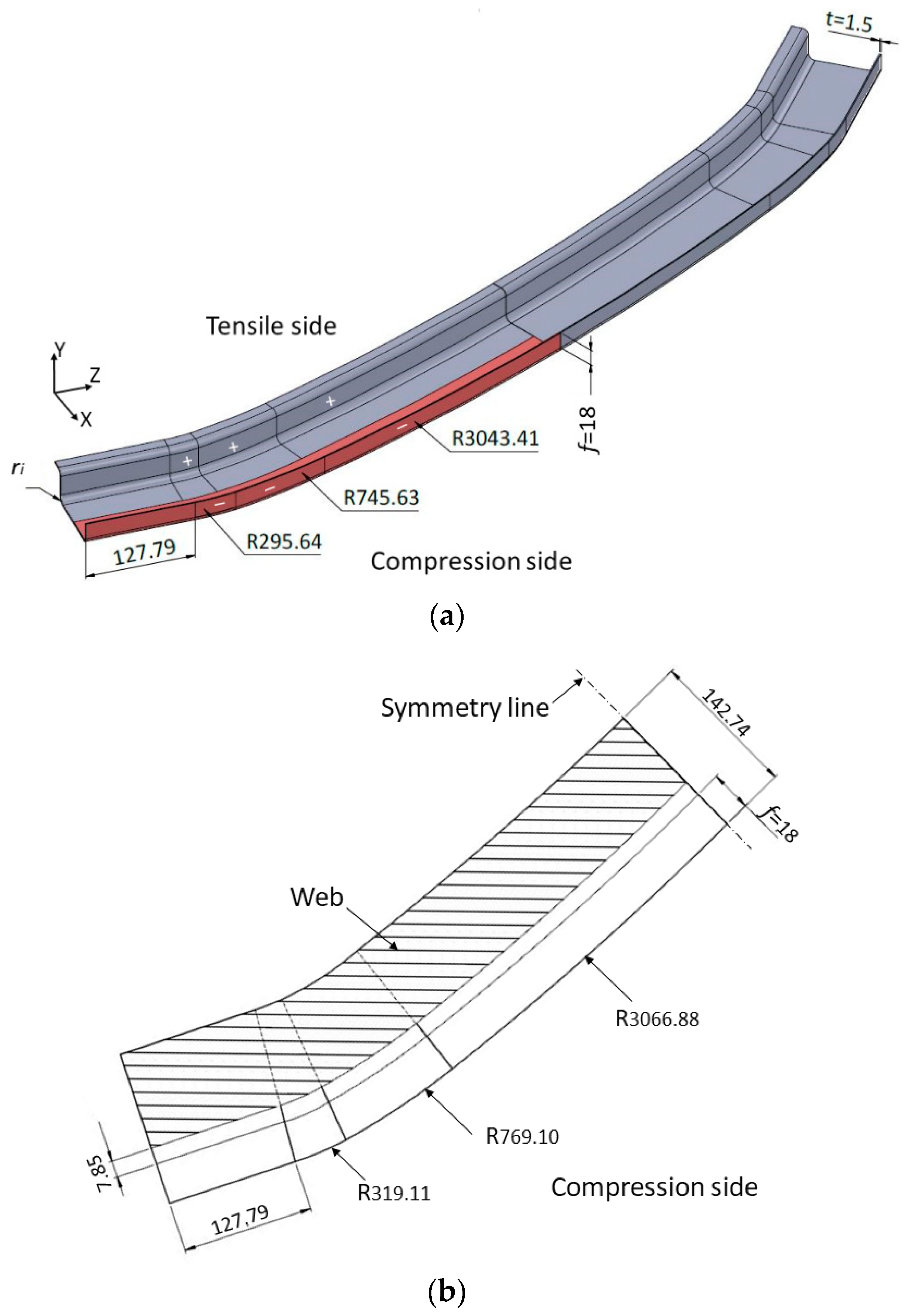
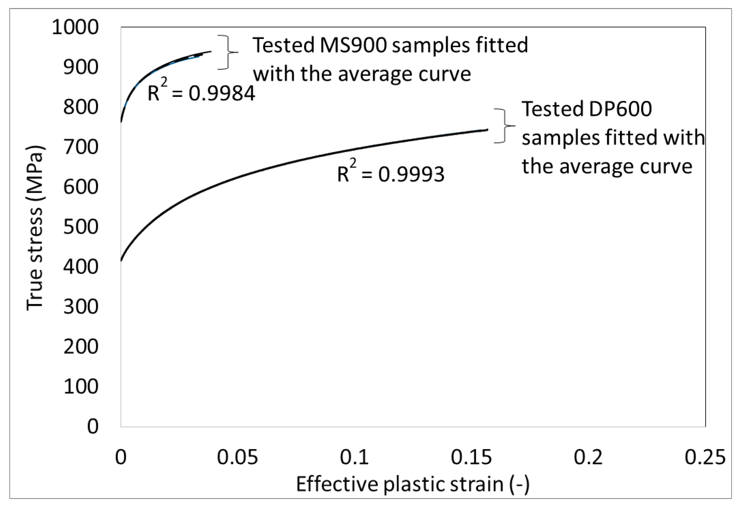
2. Profile Geometry Materials

The cross-section of the component selected for this study varies in width along the component length; see Figure 1a. The component has a flange length f = 18 mm, an inner radius ri = 5 mm, and a material thickness of t = 1.5 mm. On one side of the component, the flange is longitudinally stretched, while on the other side of the part, the compression side, the flange is longitudinally compressed. Wrinkling is only expected to occur on the compression side, and this study is limited to the forming of the compression side of the profile. Due to shape symmetry around the X-Y plane, only one-quarter of the component (highlighted in red) is investigated. The pre-cut blank that corresponds to the investigated quarter of the component is shown in Figure 1b.
The forming of one dual-phase steel (DP600) and of one martensitic steel (MS900) was investigated. All materials had a sheet thickness of 1.5 mm. Tensile tests were performed on a 30-kN Instron 5967 according to ASTM E8/E8M [26]. For each material, three bone-shaped specimens were tested along the rolling direction with a test speed of 0.025 mm s−1. Figure 2 shows the results of the tested samples superimposed with the averaged true stress–effective plastic strain curve for each material. As can be shown, almost identical tensile curves are generated for each material, and the fitted curve has an R2 value above 0.99. The strength coefficient and the strain hardening exponent are obtained by fitting the Hollomon’s power law equation to the true stress-effective plastic strain data, and the resulting parameters are given in Table 1.

3. The Experimental Setup

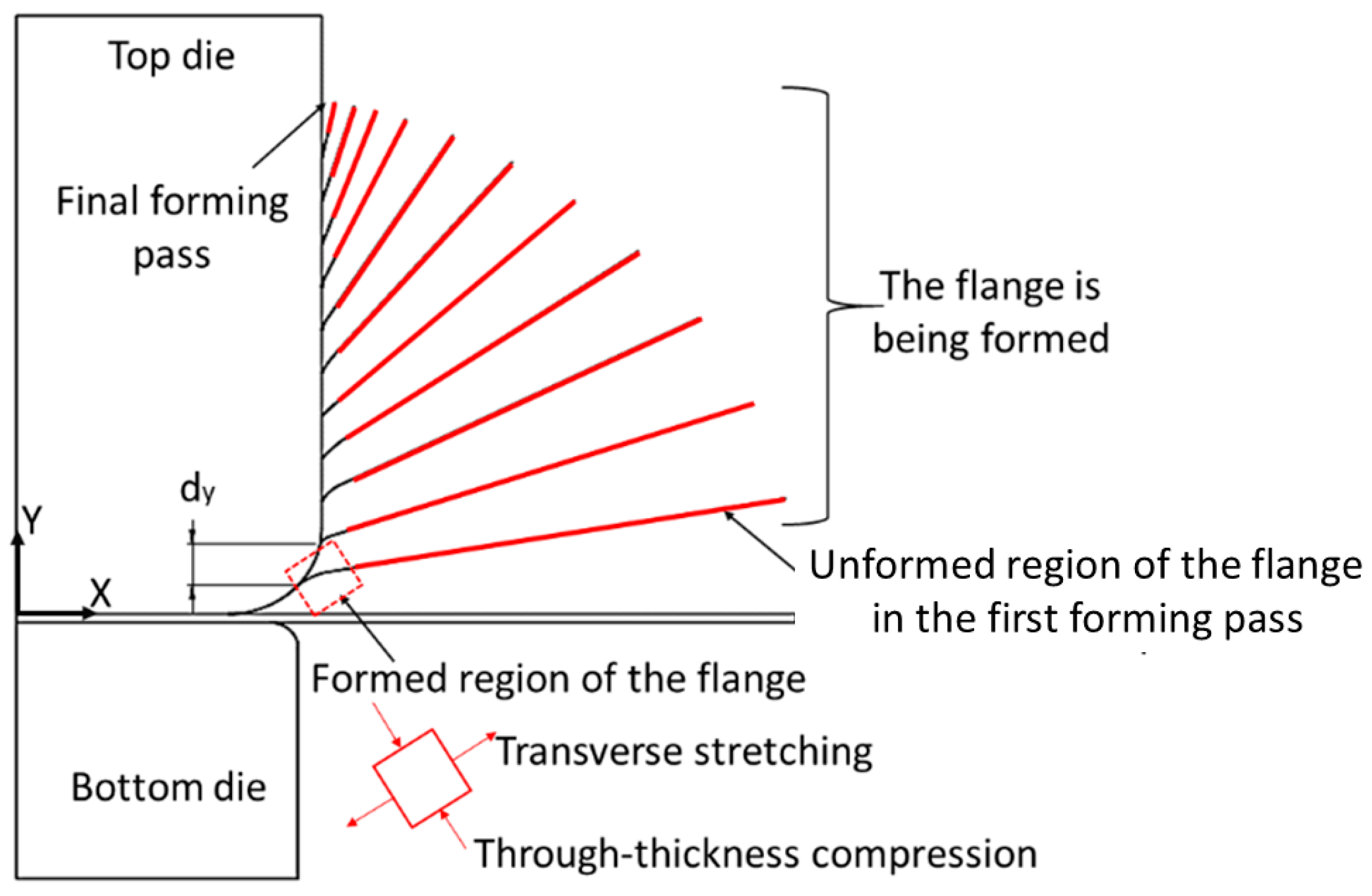
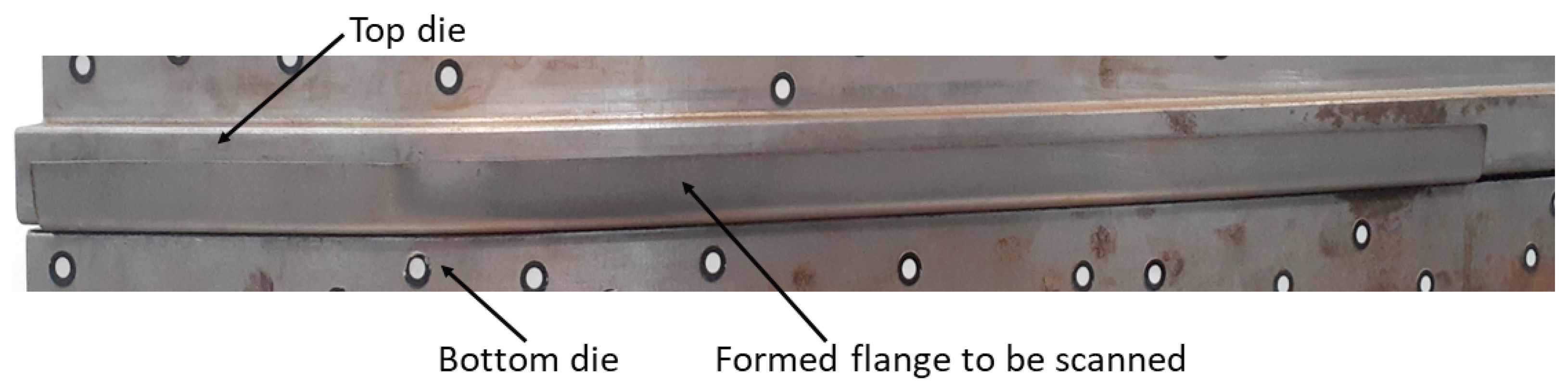
3.1. Incremental Shape Rolling

In ISR, a set of hydraulic cylinders provides the clamping force to hold the pre-cut blank between the top and bottom dies. The roll is placed at a distance from the top roll with an x-clearance set equal to the sheet thickness, in addition, the roll has a 15° inclined angle to the top die; see Figure 3a. The effect of different inclining angles on the forming quality has not been tested, since there is a limitation in the forming facility regarding the maximum inclining angle that can be set, therefore, to avoid the collapse between the machine’s components, the maximum possible inclined angle of 15° is chosen. The forming roll is first moved up incrementally in the Y-direction (dy), and then the clamping dies with the pre-cut blank move linearly in the longitudinal Z-direction. The forming roll is mounted on a hexapod that has six degrees of freedom so that the roll can move in the X-Z plane to follow the top die contour while keeping the clearance, t. The roll rotates around the Y-axis to keep its axis perpendicular to the roll path; see Figure 3b. In the next forming pass, the roll again incrementally moves up in the Y-direction, and then the clamping dies and the forming rolls repeat the same movement as the previous forming pass. The total number of forming passes depends on the flange height, f, and the applied increment size (dy). A cylindrical forming roll with a roll nose radius, Rn = 1 mm, a roll diameter, Rd = 200 mm; and a roll width, Rw = 50 mm was used in this investigation; see Figure 3a.
The same forming sequence as applied for the ISR of a U-channel in previous work [21] was implemented in this study to form the variable width profile. Thereby the flange is incrementally wrapped around the roll and formed upwards until the pre-cut is fully formed to the desired shape; see Figure 4. In this way, a high transverse stretching is generated in the formed region of the flange. Previous work [21] suggests that a smaller increment size, dy, results in a higher transverse strain and therefore reduces flange wrinkling. Therefore, this study used the smallest possible increment size, dy = 1 mm.
Since the ISR flange is formed with the roll radius, line scratches are developed in the outer surface of the flange. In the previous ISR work [27], the average surface roughness (Ra) of the pre-cut blank and the formed flange were measured by the LEXT 3D measuring laser microscope OLS4100. This showed that the surface roughness decreases with the material strength. The following ISR study [21] further suggests that the surface scratches can be significantly reduced by using forming rolls with a bigger roll nose radius.

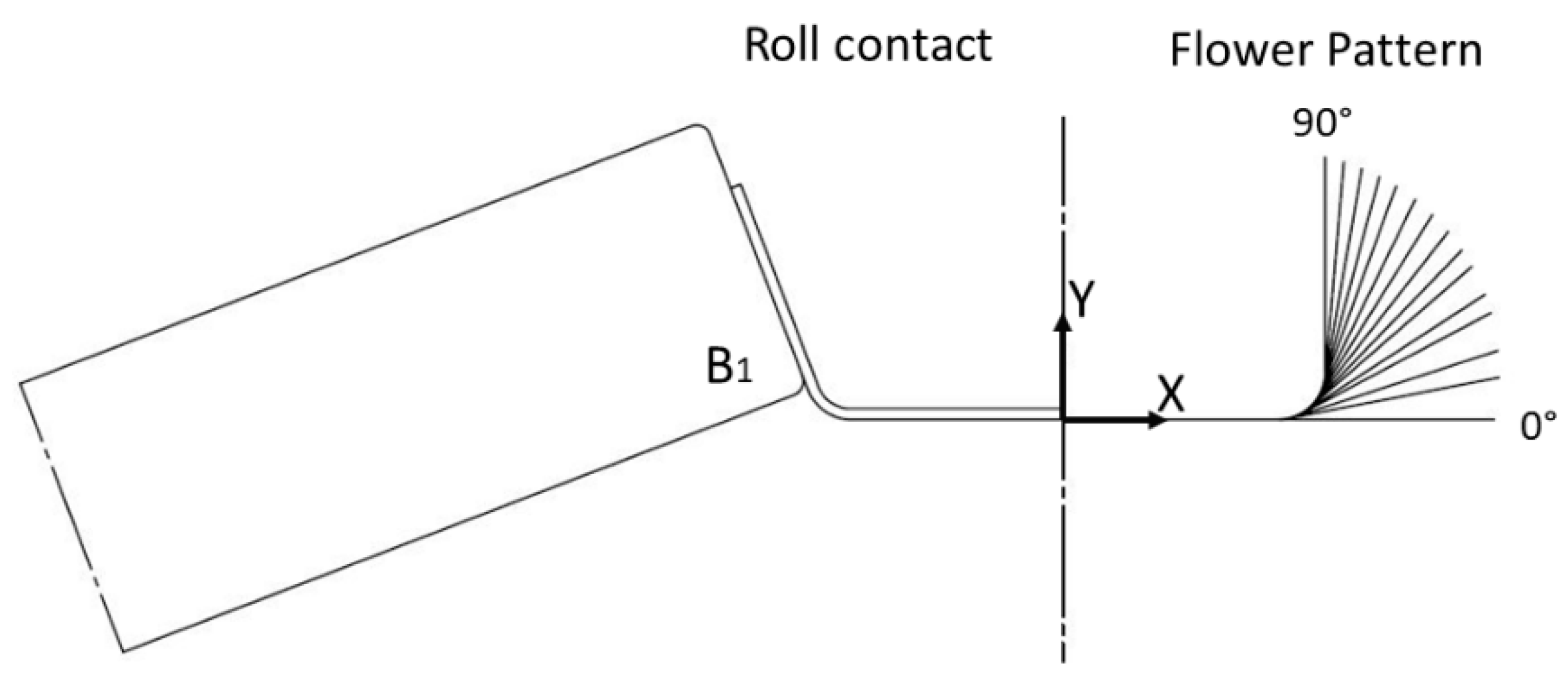
3.2. Flexible Roll Forming
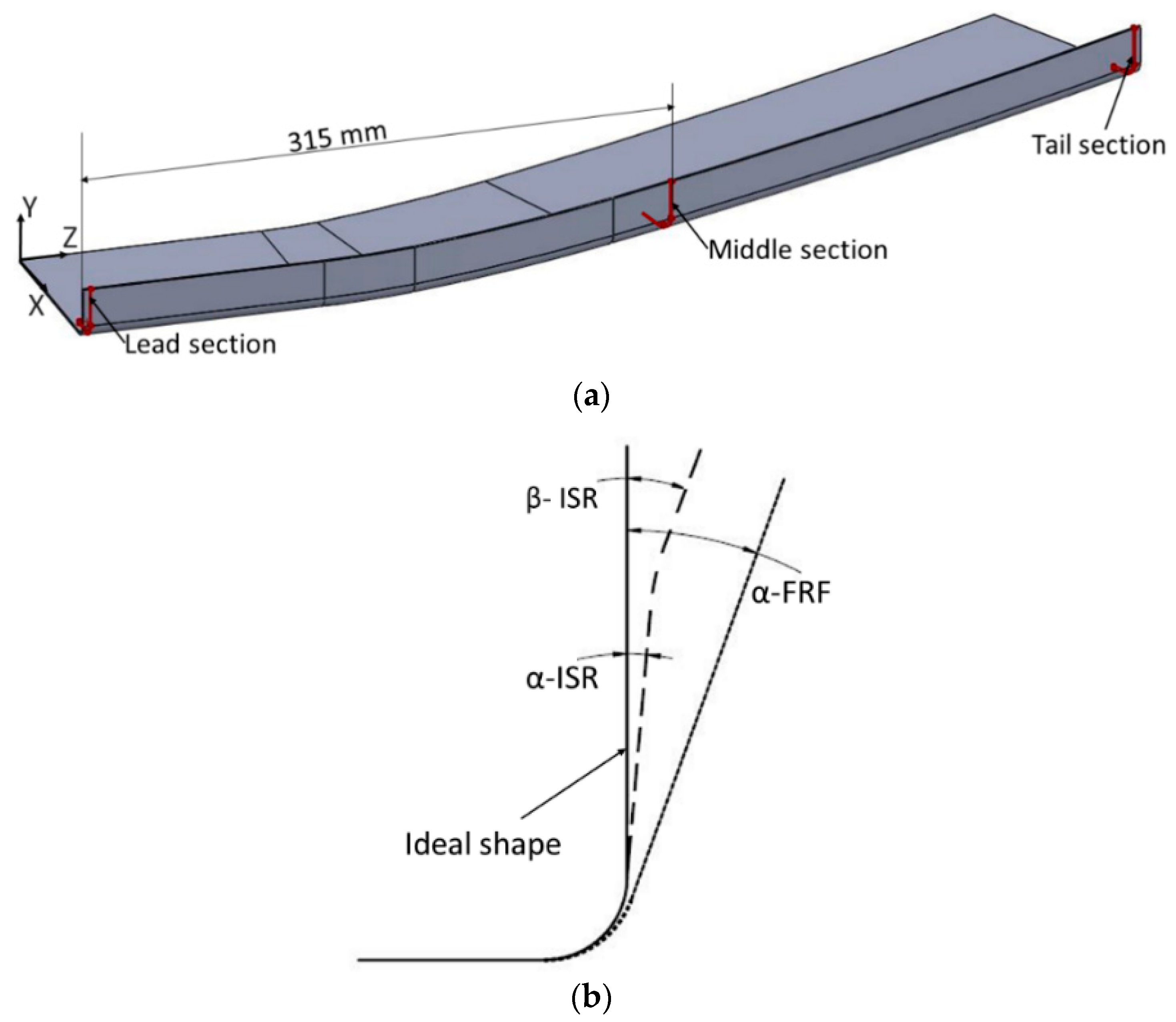
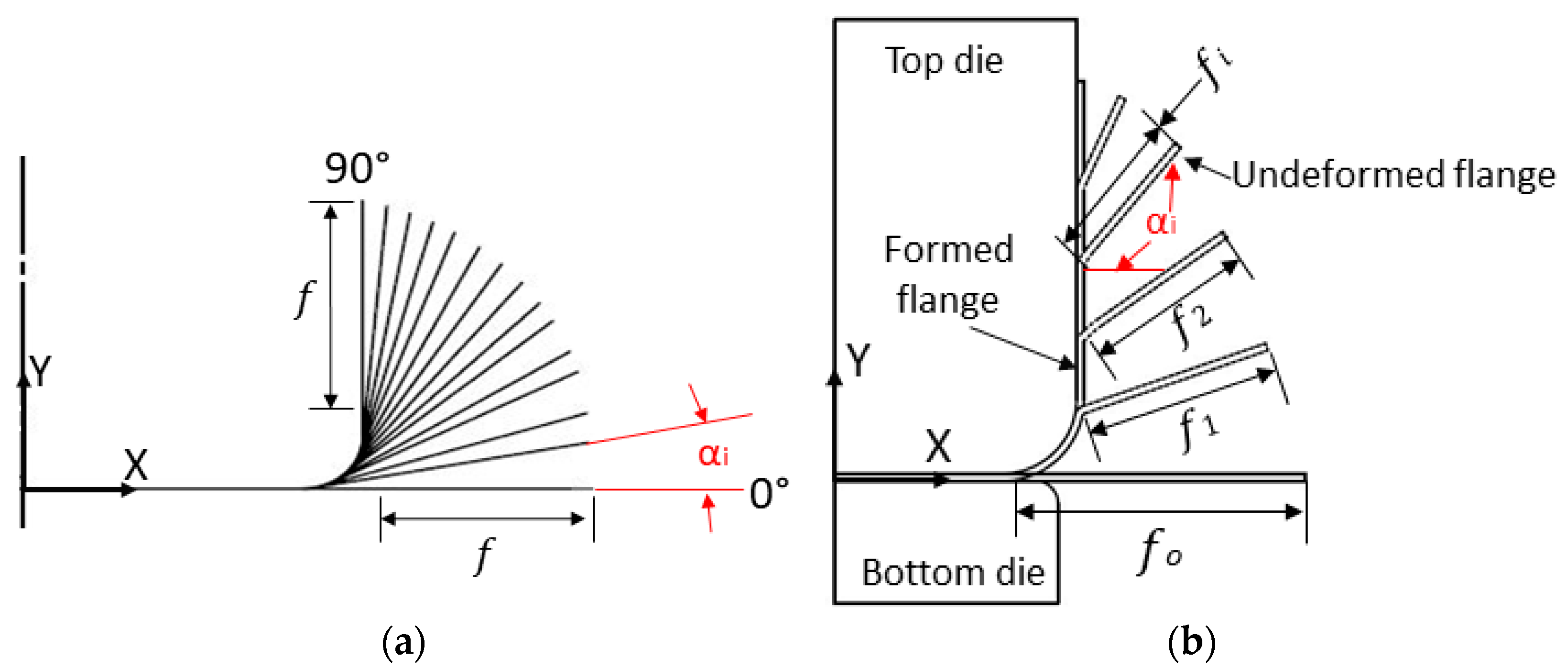
In the flexible roll forming process, the pre-cut is clamped between the same two dies used in the ISR setup, and then in each FRF forming pass, a bottom roll (B1) is used to bend the sheet into the designed angle according to the flower pattern shown in Figure 5, and similar to ISR, the clamping dies with the pre-cut blank move linearly in the longitudinal Z-direction, while the roll moves in the X-Z plane to follow the top die contour and rotates around the Y-axis to keep its axis perpendicular to the roll path (see Figure 3b). In this way, the clearance between the roll and top die will be kept constant across the forming pass. Based on the FRF forming sequence, transverse bending is the major forming mechanism (see Figure 5). The schematic of the roll tool contact with the flange during forming is shown on the left side of Figure 5, while the flower pattern (bend sequence) is shown on the right side of Figure 5. The FRF process was completed in 14 forming passes with bend angle increments of 11°, 7°, 10°, 5°, 8°, 5°, 6°, 6°, 6°, 6°, 5°, 5°, 5°, and 5°. Only one FRF condition was tested and compared with ISR; see Table 2.

3.3. Shape Analysis

The outer surface of the formed flange was scanned with a 3D laser scanner, the “CreaForm HandyScan 700” [28], before the component was released from the clamping dies, Figure 6. The evaluation of the deformed flange was completed in the Geomagic Qualify software 2021 [29].
The springback was evaluated while the formed part was held between the clamping dies. For the springback analysis, the scanned flange was imported into the Geomagic software, and three section cuts were created at the lead, middle (center length of the part), and tail sections; see Figure 7a. Note that the profile end where the forming pass started is the lead end, while the tail end is where the forming pass ends. The springback angle was calculated with Equation (1), which is the difference between the ideal angle (90°) and the angle after forming.
α = 90 ° α
where Δα is the springback angle and α is the measured angle after the forming rolls were released. As reported in [21], a smaller transverse plastic deformation is formed near the flange edge. This is due to the small level of flange wrapping over the roll radius in the later forming passes and leads to a cross-section shape deviation near the flange edge, i.e., the formed flange is not straight; see Figure 7b. The angle β qualitatively represents this shape error [21].

4. The Finite Element Analysis

The incremental shape rolling (ISR) and the flexible roll forming (FRF) processes were simulated with Abaqus Implicit, and the forming rolls, the top die, and the bottom die were modeled as rigid bodies. The pre-cut blank was meshed with reduced integration, hexahedral, linear brick elements C3D8R [30]. A mesh sensitivity analysis has been carried out, and the results of springback and flange buckle are converged at a mesh size of 1 mm in the X-direction and 2.5 mm in the Z-direction in the flange region, while four layers of elements were used through the blank thickness; see Figure 8. Due to the shape symmetry, only one-quarter of the variable width profile was modeled using a symmetry boundary condition about the X-Y plane; see Figure 8. An X-lock boundary condition (U1 = 0) was applied on the nodes along the front edge of the blank to restrict material movement in the x-direction. To prevent material from moving in the Z-direction during forming, a Z-lock boundary condition (U3 = 0) was applied on all nodes in the symmetry plane of the blank.
Given that the forming roll is mounted on a bearing and free to rotate, a surface-to-surface “frictionless contact” combined with the “hard contact condition” was defined between the forming roll and the sheet surface [31].
The experimental FRF trials are designed in such a way that in each forming pass, the clamping dies, and the pre-cut blank move in the longitudinal direction with a linear speed of 1 m/min, while the forming roll moves in the X-Z plane and rotates about the Y-axis to keep a constant gap between the roll and the top die and to keep the roll axis perpendicular to the tool path. In contrast to this, in the FEM, the blank is clamped between the die set, which is fixed in the space, and the forming roll moves in the X-Z plane and rotates around the Y-axis to follow the top die’s contour; see Figure 9. Since the static implicit solver is used in this study, the forming speed does not affect the forming quality.
The Poisson’s ratio, ν, and the Young’s modulus were assumed to be 0.3 and 200 GPa, respectively [20]. The plastic part of the true stress-true strain curves shown in Figure 2 was used together with the von Mises yield criteria and isotropic hardening to define the plastic material behavior [20].

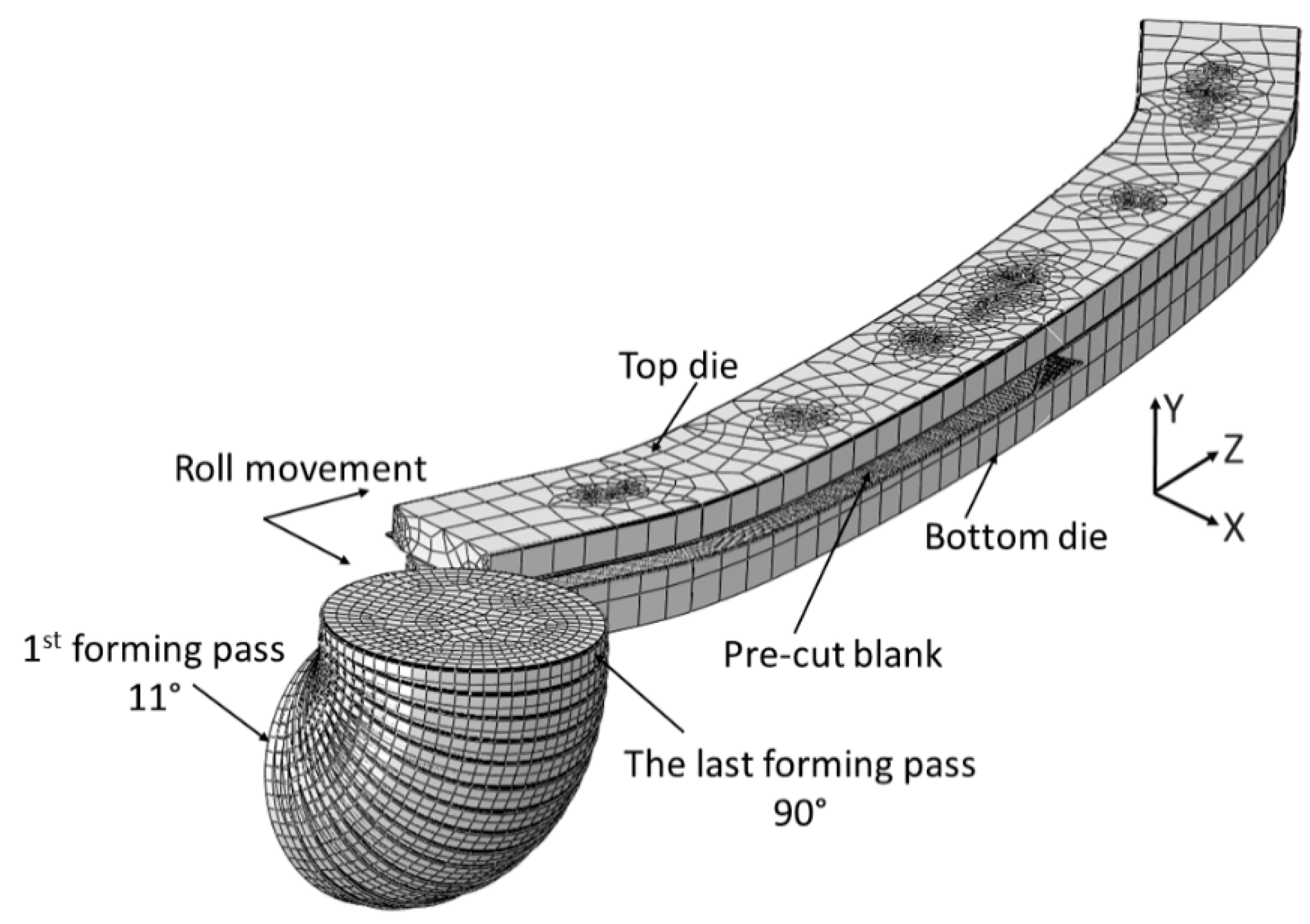
4.1. The ISR Process

In the experimental process, the clamping dies and the pre-cut blank move back and forth while the forming roll incrementally moves upwards in the Y-direction before it changes its angle and position to follow the part contour (see Figure 3b). In the finite element model (Figure 9), the pre-cut blank is clamped between the two dies, and the whole setup is fixed in space while the forming roll is incrementally moved upwards in the Y-direction before it is moved in the longitudinal direction where it follows the top die contour. As in the experimental set-up, the 2D roll path is repeated several times with the number of forming passes depending on the flange height, f, and the implemented increment size, dy.

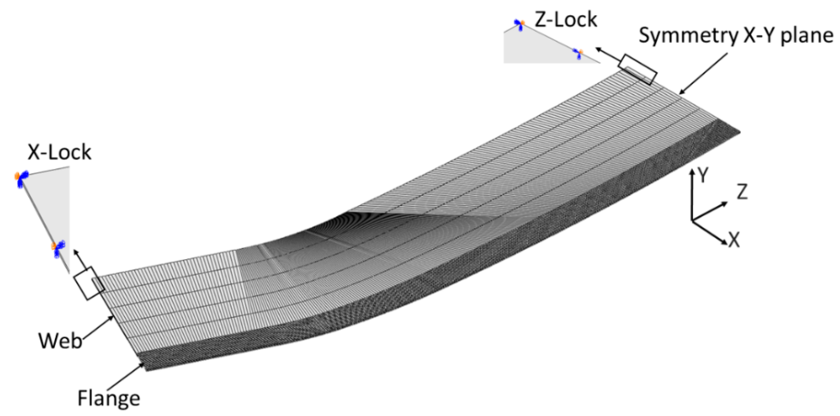
4.2. The FRF Process

The FRF process was modeled with 14 rigid roll tool sets, with each roll tool having a different angle and position. While the clamping dies and the pre-cut sheet are fixed in space, the forming roll is moved in the X-Z plane to follow the top die contour and form the pre-cut blank to shape; see Figure 10. All forming passes were performed with the same cylindrical roll; see Figure 5.

5. Results

5.1. Flange Wrinkling
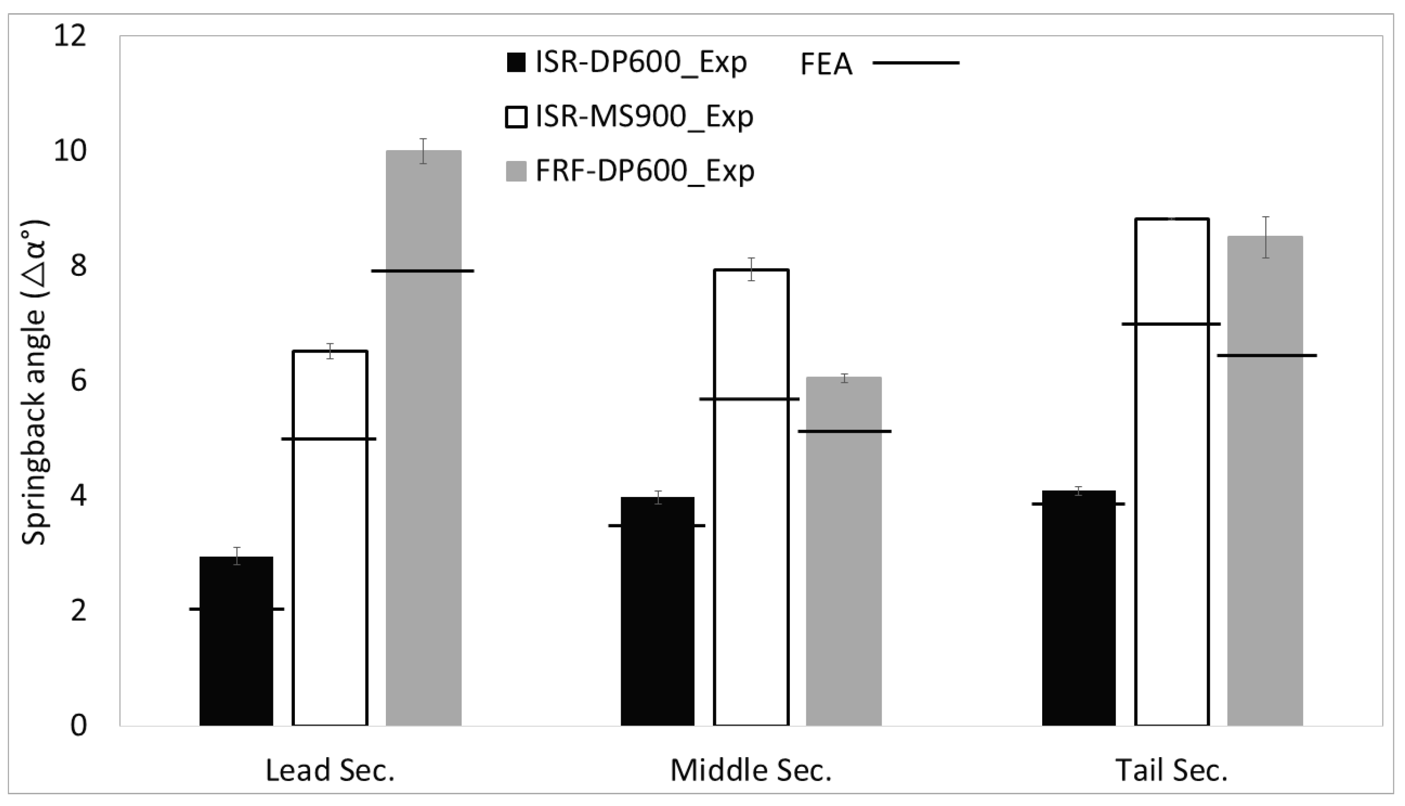
The results show that buckling and wrinkling occur in the critical zone of the flange, Figure 11a, while outside of this zone, no buckling or wrinkling was observed. To clearly illustrate the buckle and wrinkle formation in the experimental and the FEA, the results of the formed flange shape in the critical forming passes are presented only over the critical zone highlighted below in the red dashed square (Figure 11a). The results are shown in the form of the side (Figure 11b) and top view (Figure 11c).
The experimental and the FEA results of the ISR flanges are shown for the DP600 and the MS900 after pass 5 in Figure 12a and Figure 12b, respectively. In both cases, a buckle is formed in pass 5. The buckle is limited to the undeformed part of the flange, and there is no buckle in the formed region of the flange. In the FRF case formed with DP600, no buckle was observed in forming pass 5, Figure 12c. The FEA shows a good agreement with the experiments regarding the buckle initiation in ISR and the formed shape for FRF after pass 5.
The buckle that developed when ISR the DP600 stably progressed with further forming. Both the experimental and the FEA results show that the formed buckle remains constrained in the undeformed flange in pass 15; see Figure 13a.
In contrast to this, when ISR the MS900, the buckle turns into a small wrinkle in pass 15, Figure 13b. When FRF, the DP600 buckling initiates in pass 6 and turns into a small wrinkle in pass 8 (bend angle of 58°), Figure 13c. For both cases where wrinkling initiates (ISR MS900—pass 15 and FRF DP600—pass 8), the FEA only predicts a buckle; see the bottom images in Figure 13b,c.
After the final forming pass, in ISR the DP600, both the experiments and the FEA results show that the buckle is formed out, Figure 14a. In contrast to this, when ISR MS900, and FRF the DP600, the developed wrinkle becomes more severe with further forming and reaches a maximum in the final forming pass in the experiments. The FEA does not reproduce the wrinkling initiation for both forming cases, nor does it predict the growth in wrinkling severity that is experimentally observed, Figure 14b,c.
In summary, the FEA reproduces the flange forming and buckle initiation accurately until wrinkling starts to initiate. After this point, the FEA fails to predict the wrinkling initiation and progression. This is expected given that the numerical representation of a localized wrinkling event would require a more advanced model that considers plastic bifurcation analysis for accurate numerical representation of wrinkling initiation and progression [32].
In order to explain these results, Section 6 represents a basic theoretical analysis that is developed with the help of the FEM results to analyze the mechanism that leads to forming out the buckle when ISR the DP600 material, while leading to severe wrinkling in FRF and ISR of the MS900 flange.

5.2. Springback

Figure 15 shows the springback, Δα, determined at the lead, middle, and tail sections after the final forming pass for ISR and FRF. In the ISR case, the springback increases with material strength. When FRF the DP600, springback is 2–3 times higher compared to the ISR condition. In the ISR conditions, the lowest springback occurs in the lead end, while the middle and tail sections show a higher springback angle. It can also be seen that the FEA gives a good prediction of the experimental trend and magnitude of springback. There is, however, a significant deviation between the absolute experimental and numerical values for the ISR MS900 and the FRF DP600 conditions. While a good correlation for springback is achieved for the ISR DP600 condition, the FEA clearly underestimates springback in the flange for the ISR MS900 condition.

6. Discussion

The results of this study have shown that ISR enables the manufacture of a wrinkle-free flange while in FRF wrinkling occurs when forming the DP600 steel. In both cases, a buckle develops in the flange in the early stages of forming. However, when FRF, the DP600 steel, this buckle grows and then turns into a wrinkle, while in ISR, the buckle forms out towards the end of the forming process. In contrast, when ISR the higher strength MS900, flange wrinkling occurs and does not form out. The major questions that arise from this are:
  • Why does a flange buckle form out in ISR while it turns into a wrinkle in the FRF process?
  • Why is the flange buckle not formed out when ISR MS900?
To produce a wrinkle-free, flexible part contour, the flange needs to be stably compressed in the longitudinal direction [19]. Therefore, in the below section, the critical buckling stress theory developed for FRF in [18] will be reviewed and applied to the ISR process.

6.1. Buckling Limit in FRF

Groche et al. [18] reported that buckling initiates in FRF when the compressive longitudinal stress in the flange edge reaches the critical buckling stress. Thus, as indicated in Equation (2), the longitudinal stress that is formed in the flange, σlongitudinal, must be lower than the critical buckling stress, σcr to prevent buckling from occurring [18]. This theory assumes that buckle initiation in the flange leads to flange wrinkling when the longitudinal stress exceeds the buckling stress limit.
σ c r > σ l o n g i t u d i n a l
The critical radius in the compression side of the pre-cut blank, which results in the highest longitudinal compression in the flange and hence the highest potential for wrinkling initiation, is R319.11 mm; see Figure 16. The theoretical longitudinal strain, εth, required to form the component shape in this critical area can be calculated using Equation (3) [20]. The previous ISR study [21] showed that the transverse tensile stretching is almost equal to the negative through-thickness strain, and the longitudinal strain is very small compared to the other two strain components. This suggests that the longitudinal strain calculated by Equation (3) is not affected by the transverse stretching during the ISR process.
Assuming isotropic hardening, the longitudinal stress, σlongitudinal, can then be obtained from the stress-strain curves of Figure 2.
ε t h = ln R f i ( 1 c o s α i ) R
where εth is the theoretical required longitudinal strain, R is the critical radius of the pre-cut blank (in the current case R = 319.11 mm), f is the flange length, α is the bend angle, and i is the forming pass number.
The critical buckling stress, σcr, can be determined according to the Euler’s equation for buckling loaded plates given in Equation (4) [18].
σ c r = k π 2 E t 2 12 1 ν 2 f i 2
where σcr is the critical buckling stress, k is the buckling factor, E is the Young’s modulus, t is the sheet thickness, f is the flange length, and ν is the Poisson’s ratio. The buckling factor k is added to consider the effect of the different geometrical parameters, load, and boundary conditions and the part contour, given that the original Euler model is limited to the compression loading of a flat plate [18]; Equation (4) is therefore semi-empirical. In a previous study aimed at the FRF of variable width profile, k was defined to be 0.42 [18,20]. In this work, the shape of the formed profile and the load and boundary conditions are the same as those tested [20].
In the FRF case, the flange length, f, is constant in all forming passes (f = fi) while the bend angle, αi, increases with the number of passes; see Figure 17a. Thus, according to Equation (3), the longitudinal compression strain and stresses increase with the number of passes while σcr remains constant (Equation (4)).

6.2. Buckling Limit in ISR

In contrast to the FRF process, in ISR the length of the undeformed flange, fi, decreases with increasing number of forming passes (Figure 17b). Given that the increment size, dy, used in this investigation is small and equals 1 mm, the undeformed flange in each pass, fi, can be calculated based on Equation (5). Note that in Figure 17b, the increment size, dy, is exaggerated, and only five forming passes are shown; this was completed to enable a clearer view.
f i = f o i   d y
where fi is the length of the undeformed flange, i is the forming pass number, fo is the initial flange length of 25 mm, and dy is the increment size. The flange length values for the different forming passes are given for both the MS900 and the DP600 in Table 3.
While in FRF the bend angle of the flange is controlled by the roll tooling, in ISR, the flange wraps over the forming roll. This results in a small flange bend angle, αi, in the earlier forming passes, while towards the end of forming, αi reaches the final bend angle of 90° as in the FRF case [21]. The level of flange wrapping cannot be controlled. In this study, therefore, αi was determined using the FEA model results. For this, a node path was created in the non-critical and wrinkle-free flange area between the middle and the tail section (see Figure 7), and αi measured while the roll was in contact with the flange. The values for αi are shown for the different forming passes in Table 3. The MS900 shows much higher values for αi in the initial stages of forming compared to the DP600. This is due to the flange wrapping less over the roll when forming the MS900, given its higher strength.

6.3. Proposed Mechanism for Buckles Forming out in ISR the DP600

Figure 18 shows the critical buckling stress, σcr, for both ISR and FRF calculated with Equation (4) for the DP600 condition. While in the FRF case, the flange length f = 18 mm stays constant, for ISR the flange length reduces, and the values of Table 3 are used. In the FRF case, the factor, k, is set to 0.42, similar to the previous study aimed at FRF the same component as that investigated in this work [20]. While for the ISR case of both DP600 and MS900, the k factor was arbitrarily chosen to best suit the experimental data set of all forming and material conditions, i.e., k starts from 0.42 in the initial condition (the initial condition in ISR and FRF is the same) and then k reduces for the ISR condition to 0.03 in pass 26. The chosen values of k in ISR reduce the slope of the critical buckling stress and allow the best explanation and description of the experimental trend observed when ISR both material conditions. The major aim was to explain the experimental and the FEA trends and not to produce a predictive material model. The k value of 0.42 in the FRF case was chosen based on [20], where the same component was flexible roll formed. A more accurate value of k can be achieved by following Groche’s approach [18], which takes into account the effect of geometrical parameters (i.e., flange length), load, and boundary conditions.
In Figure 18, for both ISR and FRF cases, the buckling initiated at a stress that is higher than the yield stress of the material shown in Figure 1, which indicates that the flange is formed with permanent buckling that remains in the flange edge after the forming pass is completed (i.e., not an elastically formed buckle).
In Figure 18b, the critical buckling stress remains constant (dotted line) for the FRF case, while in ISR it increases exponentially towards the end of forming, Figure 18a. The longitudinal stress, σlongitudinal, that results from forming the critical area of the flange is also shown in Figure 18a,b. As explained before, to determine the longitudinal stress, the theoretical longitudinal compression strain, εth is calculated with Equation (3), and based on this, the longitudinal stress is determined for each forming pass using the plastic stress-strain curves of Figure 2. While for FRF the forming angle, αi, is taken from Table 2, in the ISR cases, αi is measured from the numerical results and given in Table 3. Based on Figure 13c, in FRF, small wrinkling is first observed in pass 8 (Figure 13c) and then grows into a severe wrinkle in pass 14 (Figure 14c). However, in Figure 18b, the longitudinal stress already reaches the critical buckling stress, σcr in pass 7 and then continues to increase in pass 8. This suggests that there is a wrinkling limit that is higher than the critical buckling stress limit proposed by Groche [13]. Reaching the critical buckling stress indicates the point of buckle initiation, but then after the buckle is formed, a further increase in compressive longitudinal stress is required to sufficiently exceed the critical buckling stress for wrinkle formation, i.e., the wrinkling limit is higher than the buckling limit. The experimental results did not reveal any buckle formation in pass 7, and further work is required to substantiate this claim experimentally.
The theoretical analysis of ISR the DP600 in Figure 18a suggests that the longitudinal stress in the flange first exceeds the critical stress in pass 5, and the experimental results confirm that a buckle develops in the flange in pass 5, see Figure 12a. However, in contrast to FRF, where the critical buckling stress stays constant, in ISR the critical stress rapidly increases in the subsequent forming passes. Therefore, in contrast to the FRF DP600 case, in ISR, after the critical buckling stress has been reached and a buckle has formed, the longitudinal stress drops under the critical buckling stress with increasing deformation, Figure 18a. This results in the buckle being formed, out at the end of forming. It is concluded that while the longitudinal compressive stress that develops when ISR the DP600 exceeds the critical buckling stress and leads to buckle formation, it does not exceed the wrinkling limit, and therefore a wrinkle is not formed.

6.4. Proposed Mechanism for the MS900 Showing Wrinkling in the Flange

Figure 19 compares the critical buckling stress with the longitudinal stress in the ISR flange edge for both the DP600 and the MS900 steel.
Based on Figure 19b, when ISR MS900 buckling should have initiated in forming pass 3, where the longitudinal stress in the flange exceeds the critical buckling stress. This does not conform with the experimental results which show that buckling does not occur before pass 5 (Figure 12b). The reason for this mismatch may be related to the bend angle, αi, being determined from the FEA. In Figure 15 it was shown that the FEA significantly underestimates the level of springback for the MS900, i.e., it does not give an accurate estimation of shape. This may have led to an overestimation of αi in the early forming stages.
Overall, Figure 19b reveals that the MS900 experiences much higher longitudinal stresses in the flange than the DP600 (Figure 19a). After exceeding the critical buckling stress in forming pass 3, the longitudinal stress rapidly increases and at some point is almost double the critical buckling stress. Only towards the end of the forming process (forming pass 16) the critical buckling begins to exceed the longitudinal stress. In contrast, when ISR the DP600, the critical stress becomes significantly higher than the longitudinal stress immediately after the buckle is formed (after pass 8). The MS900 is therefore much more prone to buckling and wrinkling initiation in the early stages of forming than the DP600.
Previous work aimed at FRF has shown that while a stable buckle can be formed out [32], a wrinkle will always lead to an increasing wrinkling severity with continuous forming.
It therefore is concluded that the wrinkling in the flange observed when ISR MS900 is due to the early initiation of a wrinkle that grows and is too severe to be formed out when the critical stress condition changes. In contrast, the DP600 only develops a buckle, which can be formed out when the critical buckling stress starts exceeding the longitudinal compressive stress in the flange.

7. Conclusions

Flange wrinkling restricts the widespread application of flexible roll forming components from AHSS in the automotive industry. The new incremental shape rolling process was applied to form a complex profile of variable depth from AHSS [21]. This showed a clear development of transverse tensile strain in the flange, which reduced the wrinkling severity.
In this study, the incremental shape rolling process is applied to form a simplified automotive component of variable width profile, and finite element analysis is used to investigate the deformation mechanisms. The information is then applied to establish simple analytical equations to explain the wrinkling reduction in incremental shape rolling based on the critical buckling stress conditions in the flange. The theoretical analysis is supported by flexible roll forming and incremental shape rolling trials performed on DP600 and MS900 steel. The following conclusions can be made:
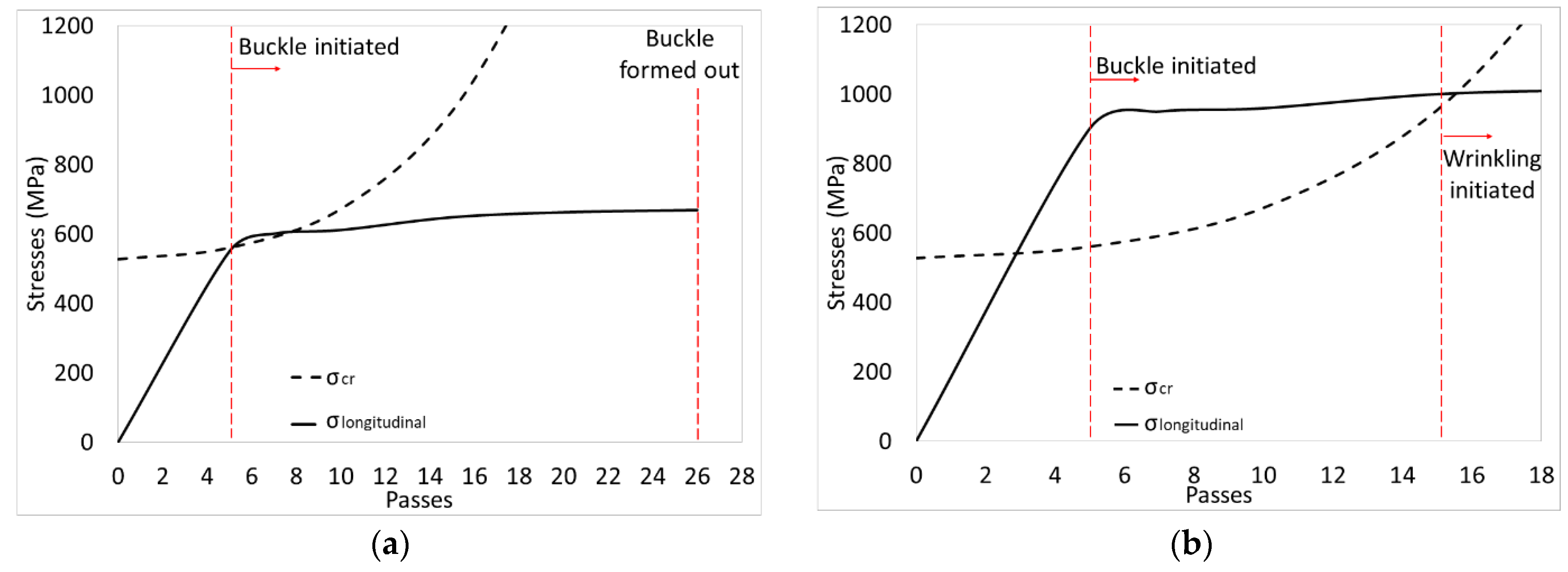
  • In both the ISR and the FRF process the critical buckling stress in the flange is exceeded, and this leads to flange buckling in the early stages of forming in all investigated forming cases and material conditions.
  • In FRF the critical buckling stress and the flange length are constant while the forming angle increases. This results in the stress condition in the flange favoring buckling growth and wrinkle initiation with further progression of forming.
  • In contrast to FRF, in ISR the critical flange length reduces with increasing the number of forming passes. This increases the critical buckling stresses towards the end of forming and leads to the buckle being formed out when applying ISR to the DP600 steel.
  • When ISR MS900 the initial flange buckle transitions into a wrinkle. This is related to the higher material strength, which results in a higher initial longitudinal stress in the flange and causes the buckle to grow into a wrinkle before the stress condition favors a buckling reduction. The developed wrinkle cannot be formed out and therefore continues to grow in severity in the subsequent passes.
Overall, this study suggests that ISR enables the flexible and low-cost manufacture of automotive part shapes from AHSS. However, further process development is needed to reduce the number of required forming passes and to develop process parameters and forming tools for producing components from UHSS at quality standards that suit automotive applications. The mechanisms identified and discussed in this work will assist in optimizing the ISR process to further reduce wrinkling issues when forming higher strength sheet metals.

Author Contributions

Conceptualization, M.W. and B.R.; methodology, A.E.; software, A.E.; validation, M.W. and A.E.; formal analysis, M.W., A.E., and B.A.; resources, M.W. and B.A.; data curation, A.E.; writing—original draft preparation, A.E.; writing—review and editing, M.W.; visualization, M.W. and A.E.; supervision, M.W., B.R., and B.A.; project administration, M.W.; funding acquisition, M.W. All authors have read and agreed to the published version of the manuscript.

Funding

This research received no external funding.

Data Availability Statement

The data presented in this study are available on request from the corresponding author due to privacy restrictions.

Acknowledgments

The authors acknowledge data M Sheet Metal Solutions GmbH for the development and manufacture of the 3D roll forming prototyping facility. The authors would like to thank Deakin University Postgraduate Research Scholarships (DUPRS) for their financial support.

Conflicts of Interest

The authors declare no conflicts of interest.

References

  1. Australian Government. The Department of Infrastructure, Transport, Regional Development and Communications. Available online: https://www.infrastructure.gov.au/infrastructure-transport-vehicles/vehicles/vehicle-safety-environment (accessed on 22 November 2022).
  2. Baluch, N.; Udin, Z.M.; Abdullah, C.S. Advanced High Strength Steel in Auto Industry: An Overview. Eng. Appl. Sci. Res. 2014, 4, 686–689. [Google Scholar] [CrossRef]
  3. Sun, G.; Deng, M.; Zheng, G.; Li, Q. Design for cost performance of crashworthy structures made of high strength steel. Thin-Walled Struct. 2019, 138, 458–472. [Google Scholar] [CrossRef]
  4. Lim, Y.; Venugopal, R.; Ulsoy, A.G. Process Control for Sheet-Metal Stamping; Springer: London, UK, 2014. [Google Scholar]
  5. Mori, K.; Bariani, P.F.; Behrens, B.A.; Brosius, A.; Bruschi, S.; Maeno, T.; Merklein, M.; Yanagimoto, J. Hot stamping of ultra-high strength steel parts. CIRP Ann. Manuf. Technol. 2017, 66, 755–777. [Google Scholar] [CrossRef]
  6. Sun, Y.; Li, Y.; Daniel, W.J.T.; Meehan, P.A.; Liu, Z.; Ding, S. Longitudinal strain development in Chain-die forming AHSS products: Analytical modelling, finite element analysis and experimental verification. J. Mater. Process. Technol. 2017, 243, 322–334. [Google Scholar] [CrossRef]
  7. Safdarian, R.; Naeini, H.M. The effects of forming parameters on the cold roll forming of channel section. Thin-Walled Struct. 2015, 92, 130–136. [Google Scholar] [CrossRef]
  8. Bui, Q.V.; Ponthot, J.P. Numerical simulation of cold roll-forming processes. J. Mater. Process. Technol. 2008, 202, 275–282. [Google Scholar] [CrossRef]
  9. Cheng, J.-J.; Cao, J.-G.; Zhao, Q.-F.; Liu, J.; Yu, N.; Zhao, R.-G. A novel approach to springback control of high-strength steel in cold roll forming. Int. J. Adv. Manuf. Technol. 2020, 107, 1793–1804. [Google Scholar] [CrossRef]
  10. Groche, P.S.R. Umformtechnik für die Produkte von morgen. Mater. Und Werkst. Mater. Sci. Eng. Technol. 2000, 31, 958–963. [Google Scholar] [CrossRef]
  11. Yan, Y.; Wang, H.; Li, Q.; Qian, B.; Mpofu, K. Simulation and experimental verification of flexible roll forming of steel sheets. Int. J. Adv. Manuf. Technol. 2014, 72, 209–220. [Google Scholar] [CrossRef]
  12. Groche, P.; Güngör, B.; Kilz, J. Straight roll formed profiles through partial rolling. CIRP Ann. 2023, 72, 229–232. [Google Scholar] [CrossRef]
  13. Badparva, H.; Naeini, H.M.; Kasaei, M.M.; Asl, Y.D.; Abbaszadeh, B.; da Silva, L.F.M. Deformation length in flexible roll forming. Int. J. Adv. Manuf. Technol. 2023, 125, 1229–1238. [Google Scholar] [CrossRef]
  14. Rezaei, R.; Moslemi Naeini, H.; Tafti, R.A.; Kasaei, M.M.; Mohammadi, M.; Abbaszadeh, B. Effect of bend curve on web warping in flexible roll formed profiles. Int. J. Adv. Manuf. Technol. 2017, 93, 3625–3636. [Google Scholar] [CrossRef]
  15. Woo, Y.Y.; Oh, I.Y.; Hwang, T.W.; Moon, Y.H. Analysis of shape defects during flexible roll forming of steel/aluminum double-layered blanks. Int. J. Mater. Form. 2019, 13, 861–872. [Google Scholar] [CrossRef]
  16. Stamp. 3D Roll Forming. The Technology of the Future: Roll Forming with Variable Section. Available online: https://www.stam.it/en/roll-forming-lines/3d-roll-forming/ (accessed on 10 December 2024).
  17. Abeyrathna, B.; Rolfe, B.; Harrasser, J.; Sedlmaier, A.; Rui, G.; Pan, L.; Weiss, M. Prototyping of automotive components with variable width and depth. In Proceedings of the 36th IDDRG Conference, Munich, Germany, 2–6 July 2017. [Google Scholar]
  18. Groche, P.; Zettler, A.; Berner, S.; Schneider, G. Development and verification of a one-step-model for the design of flexible roll formed parts. Int. J. Mater. Form. 2010, 4, 371–377. [Google Scholar] [CrossRef]
  19. Kasaei, M.M.; Naeini, H.M.; Abbaszadeh, B.; Mohammadi, M.; Ghodsi, M.; Kiuchi, M.; Zolghadr, R.; Liaghat, G.; Tafti, R.A.; Tehrani, M.S. Flange wrinkling in flexible roll forming Process. Procedia Eng. 2014, 81, 245–250. [Google Scholar] [CrossRef]
  20. Abeyrathna, B.; Ghanei, S.; Rolfe, B.; Taube, R.; Weiss, M. Optimising part quality in the flexible roll forming of an automotive component. Int. J. Adv. Manuf. Technol. 2021, 118, 3361–3373. [Google Scholar] [CrossRef]
  21. Essa, A.; Abeyrathna, B.; Rolfe, B.; Weiss, M. Incremental shape rolling of a variable depth profile. J. Mater. Process. Technol. 2023, 316, 117964. [Google Scholar] [CrossRef]
  22. Wang, L.; Long, H. Investigation of material deformation in multi-pass conventional metal spinning. Mater. Des. 2011, 32, 2891–2899. [Google Scholar] [CrossRef]
  23. Music, O.; Allwood, J.M.; Kawai, K. A review of the mechanics of metal spinning. J. Mater. Process. Technol. 2010, 210, 3–23. [Google Scholar] [CrossRef]
  24. Jia, Z.; Li, L.; Han, Z.R.; Fan, Z.J.; Liu, B.M. Experimental study on wrinkle suppressing in multi-pass drawing spinning of 304 stainless steel cylinder. Int. J. Adv. Manuf. Technol. 2018, 100, 111–116. [Google Scholar] [CrossRef]
  25. Essa, A.; Abeyrathna, B.; Rolfe, B.; Weiss, M. Incremental shape rolling of top-hat shaped automotive structural and crash components. J. Mater. Process. Technol. 2023, 321, 118162. [Google Scholar] [CrossRef]
  26. ASTM E8/E8M-22; Standard Test Methods for Tension Testing of Metallic Materials. ASTM: West Conshohocken, PA, USA, 2016.
  27. Essa, A.; Abeyrathna, B.; Rolfe, B.; Weiss, M. Prototyping of straight section components using incremental shape rolling. Int. J. Adv. Manuf. Technol. 2022, 121, 3883–3901. [Google Scholar] [CrossRef]
  28. HandyScan3D. n.d. Available online: https://www.creaform3d.com/en (accessed on 10 November 2022).
  29. Geomagic. n.d. Available online: http://www.geomagic.com/en/ (accessed on 10 November 2022).
  30. Abaqus_Documentation. n.d. Available online: https://classes.engineering.wustl.edu/2009/spring/mase5513/abaqus/docs/v6.6/index.html (accessed on 8 December 2022).
  31. Woo, Y.Y.; Han, S.W.; Oh, I.Y.; Moon, Y.H. Shape defects in the flexible roll forming of automotive parts. Int. J. Automot. Technol. 2019, 20, 227–236. [Google Scholar] [CrossRef]
  32. Sreenivas, A.; Abeyrathna, B.; Rolfe, B.; Weiss, M. Development of a reversible top-hat forming approach for reducing flange wrinkling in flexible roll forming. Int. J. Mech. Sci. 2023, 252, 108359. [Google Scholar] [CrossRef]
Figure 1. Schematic showing (a) the full variable width profile and (b) the pre-cut blank corresponding to the investigated quarter of the component (dimensions in mm).
Jmmp 08 00290 g001
Figure 2. Averaged true stress-effective plastic strain curve of the tested AHSS.
Jmmp 08 00290 g002
Figure 3. (a) Schematic drawing of the ISR process of the variable width profile and (b) top view showing the roll path, dimensions in mm.
Jmmp 08 00290 g003
Figure 4. Schematic showing an example of the ISR forming sequence.
Jmmp 08 00290 g004
Figure 5. Schematic of the forming roll used in the FRF process and the implemented flower pattern.
Jmmp 08 00290 g005
Figure 6. Formed flange to be scanned before the component was released from the clamping dies.
Jmmp 08 00290 g006
Figure 7. (a) The three section cuts considered for springback analysis and (b) the formed angles after the final forming pass in ISR and FRF.
Jmmp 08 00290 g007
Figure 8. Boundary conditions applied on the pre-cut blank.
Jmmp 08 00290 g008
Figure 9. The finite element model of the ISR process.
Jmmp 08 00290 g009
Figure 10. The finite element model of the FRF process.
Jmmp 08 00290 g010
Figure 11. (a) Schematic showing the location of the section cut in the critical zone considered to illustrate the results of the flange shape, (b) side view, and (c) top view.
Jmmp 08 00290 g011
Figure 12. The experimental and the FEA results of the flange formed with (a) ISR DP600 after pass 5, (b) ISR MS900 after pass 5, and (c) FRF DP600 after pass 5 (bend angle 49°).
Jmmp 08 00290 g012
Figure 13. The experimental and the FEA results of the flange formed with (a) ISR DP600 after pass 15, (b) ISR MS900 after pass 15, and (c) FRF DP600 after pass 8 (bend angle 58°).
Jmmp 08 00290 g013
Figure 14. The experimental and the FEA results of the flange formed with (a) ISR DP600 after pass 26, (b) ISR MS900 after pass 26, and (c) FRF DP600 after pass 14 (bend angle 90°).
Jmmp 08 00290 g014
Figure 15. The experimental and FEA results for the springback angle after the final forming pass for FRF of DP600 and ISR of DP600 and MS900.
Jmmp 08 00290 g015
Figure 16. Schematic showing the parameters used to calculate the theoretical longitudinal strain (dimensions in mm).
Jmmp 08 00290 g016
Figure 17. Schematic showing the flange length for different forming stages (a) FRF and (b) ISR.
Jmmp 08 00290 g017
Figure 18. Comparison between the longitudinal stress and the critical buckling stress for (a) ISR DP600 and (b) FRF DP600.
Jmmp 08 00290 g018
Figure 19. Comparison between the longitudinal stress and the critical buckling stress for the ISR cases (a) ISR DP600 and (b) ISR MS900.
Jmmp 08 00290 g019
Table 1. Tensile data of the investigated AHSS.
Material0.2% Yield
Strength (MPa)
Strain Hardening
Exponent (n)
Strength Coefficient, K
(MPa)
DP 600414.50.11897
MS 900763.20.081250
Table 2. The conditions tested for FRF and ISR.
Experiment SetMaterialIncrement Size
dy (mm)
Corresponding Forming PassesFlange Length
f (mm)
Forming
Angle (α°)
ISRDP 600 and MS 90012618
FRFDP 600 141811, 7, 10, 5, 8, 5, 6, 6, 6, 6, 5, 5, 5, 5
Table 3. The flange lengths and bend angles for the different forming passes for ISR.
Flange Length fiBend Angle (αi°)
Pass DP600MS900
52043.7747.07
101565.271.56
151082.2586.52
20587.6987.69
2419090
Disclaimer/Publisher’s Note: The statements, opinions and data contained in all publications are solely those of the individual author(s) and contributor(s) and not of MDPI and/or the editor(s). MDPI and/or the editor(s) disclaim responsibility for any injury to people or property resulting from any ideas, methods, instructions or products referred to in the content.

