Review

Condition Monitoring in Additive Manufacturing: A Critical Review of Different Approaches

by
Khalil Khanafer
1,*,
Junqian Cao
1 and
Hussein Kokash
2
1
Division of Engineering Technology, College of Engineering and Technology, University of Michigan, Flint, MI 48502, USA
2
Mechanical Engineering, Wayne State University, Detroit, MI 48202, USA
*
Author to whom correspondence should be addressed.
J. Manuf. Mater. Process. 2024, 8(3), 95; https://doi.org/10.3390/jmmp8030095
Submission received: 4 April 2024 / Revised: 27 April 2024 / Accepted: 1 May 2024 / Published: 4 May 2024

Abstract

:
This critical review provides a comprehensive analysis of various condition monitoring techniques pivotal in additive manufacturing (AM) processes. The reliability and quality of AM components are contingent upon the precise control of numerous parameters and the timely detection of potential defects, such as lamination, cracks, and porosity. This paper emphasizes the significance of in situ monitoring systems—optical, thermal, and acoustic—which continuously evaluate the integrity of the manufacturing process. Optical techniques employing high-speed cameras and laser scanners provide real-time, non-contact assessments of the AM process, facilitating the early detection of layer misalignment and surface anomalies. Simultaneously, thermal imaging techniques, such as infrared sensing, play a crucial role in monitoring complex thermal gradients, contributing to defect detection and process control. Acoustic monitoring methods augmented by advancements in audio analysis and machine learning offer cost-effective solutions for discerning the acoustic signatures of AM machinery amidst variable operational conditions. Finally, machine learning is considered an efficient technique for data processing and has shown great promise in feature extraction.

1. Introduction

Additive manufacturing (AM) technologies have undergone successful development and gained increasing attention from both academia and industry in recent years. Numerous application scenarios result in significant benefits from these techniques, spanning diverse fields such as robotics, electronics, automotive, and aerospace [1,2,3]. Additive manufacturing, also known as 3D printing or rapid prototyping, involves the layer-by-layer production of parts based on CAD models. This process allows for the creation of objects with complex structures, an achievement that is often unattainable using traditional methods [4,5,6,7]. Geometrical design constraints are notably reduced, leading to cost savings. Consequently, additive manufacturing holds great potential to surmount the prevailing challenges in the traditional manufacturing domain. Additive manufacturing covers a wide range of techniques and technologies, each with their own unique approach to building objects layer by layer. Some of different types of AM techniques include material extrusion (MEX), powder bed fusion (PBF), binder jetting (BJT), and directed energy deposition (DED). While additive manufacturing technologies have seen significant development and yielded promising outcomes, ensuring the mechanical integrity of the manufactured components remains a challenge. It is necessary to maintain caution in monitoring the AM process and inspecting the parts’ quality during production [8]. Detecting defects in the early stages of printing could trigger an alert to either pause or halt the printing process. This allows for corrective measures to be implemented promptly, mitigating the necessity to reprint the parts. The quality of the printed parts is heavily influenced by factors such as the material properties and the potential emergence of defects, like lamination and cracks [9,10], porosity [11,12], powder bed anomalies [13,14], balling [15,16], and residual stress [17]. Hence, achieving the precise monitoring of the manufacturing process within the area of AM is necessary for the enhancement of the parts’ quality and cost reduction [18,19]. Nonetheless, this undertaking poses significant challenges during practical implementations due to the difficult nature of the process and the complexities involved in analyzing noisy-condition monitoring data.
Monitoring aids play a crucial role in enhancing the quality of printed parts in additive manufacturing processes. These aids encompass various techniques and technologies designed to detect and mitigate the defects, ensure process stability, and optimize the printing parameters. Real-time monitoring systems, such as optical and thermal imaging, acoustic sensors, and vibration analysis, provide valuable insights into the printing process, enabling the operators to identify anomalies and make timely adjustments to maintain the quality standards. Additionally, in-line monitoring tools, including laser scanners and 3D metrology systems, facilitate the inspection of printed parts during production, allowing for immediate feedback and quality control. Furthermore, advanced data analytics and machine learning algorithms can analyze monitoring data to predict potential defects and optimize the printing parameters for improved quality and efficiency. By integrating monitoring aids into additive manufacturing workflows, manufacturers can acquire higher-quality printed parts, reduce the scrap rates, and enhance the overall process reliability.
To address this, condition monitoring employs a variety of tools and strategies, including real-time sensors, thermal imaging, acoustic monitoring, and machine vision systems [20]. These techniques continuously assess factors such as the temperature gradients, layer adhesion, dimensional accuracy, and surface defects during the printing process. By detecting anomalies and deviations from the desired specifications, condition monitoring allows for timely adjustments, reducing the risk of defects and ensuring the production of high-quality AM parts. As the field of additive manufacturing continues to expand, condition monitoring will remain a critical component in maintaining process control and enhancing the overall reliability of 3D-printed components across various industries [21,22]. In summary, condition monitoring is essential in additive manufacturing to uphold the products’ quality, improve the process efficiency, reduce the costs, enhance reliability, and ensure safety and compliance with the industry standards. It is a critical component for the continued growth and adoption of AM in various industries. In the scope of this investigation, we will conduct comprehensive analysis, a discussion, and the comparative evaluation of different condition monitoring techniques. These techniques are employed with the aim of elevating both the quality and efficiency of products produced through various additive manufacturing methodologies. This analysis will provide a deeper understanding of the complicated relationship between monitoring strategies and AM processes, shedding light on how the effective utilization of these techniques can lead to improved final product attributes, increased operational efficiency, and cost savings. This study is positioned to contribute valuable insights to the ever-evolving landscape of AM, where quality assurance and process optimization are paramount in achieving the industry’s and consumers’ expectations.

2. Condition Monitoring Techniques

Certainly, there are various methods of condition monitoring in AM to ensure the quality and reliability of printed components. In this section, our emphasis is directed towards in situ monitoring systems and defect identification methodologies tailored for AM. Some typical examples of defects are presented in Figure 1. To commence, we provide a summary of the defect detection process and outline the requisites for monitoring techniques. Subsequently, we conduct an in-depth examination of a range of approaches pertaining to data acquisition and data analysis, all of which play pivotal roles in the thorough inspection of defects in the AM process.

2.1. Optical Techniques

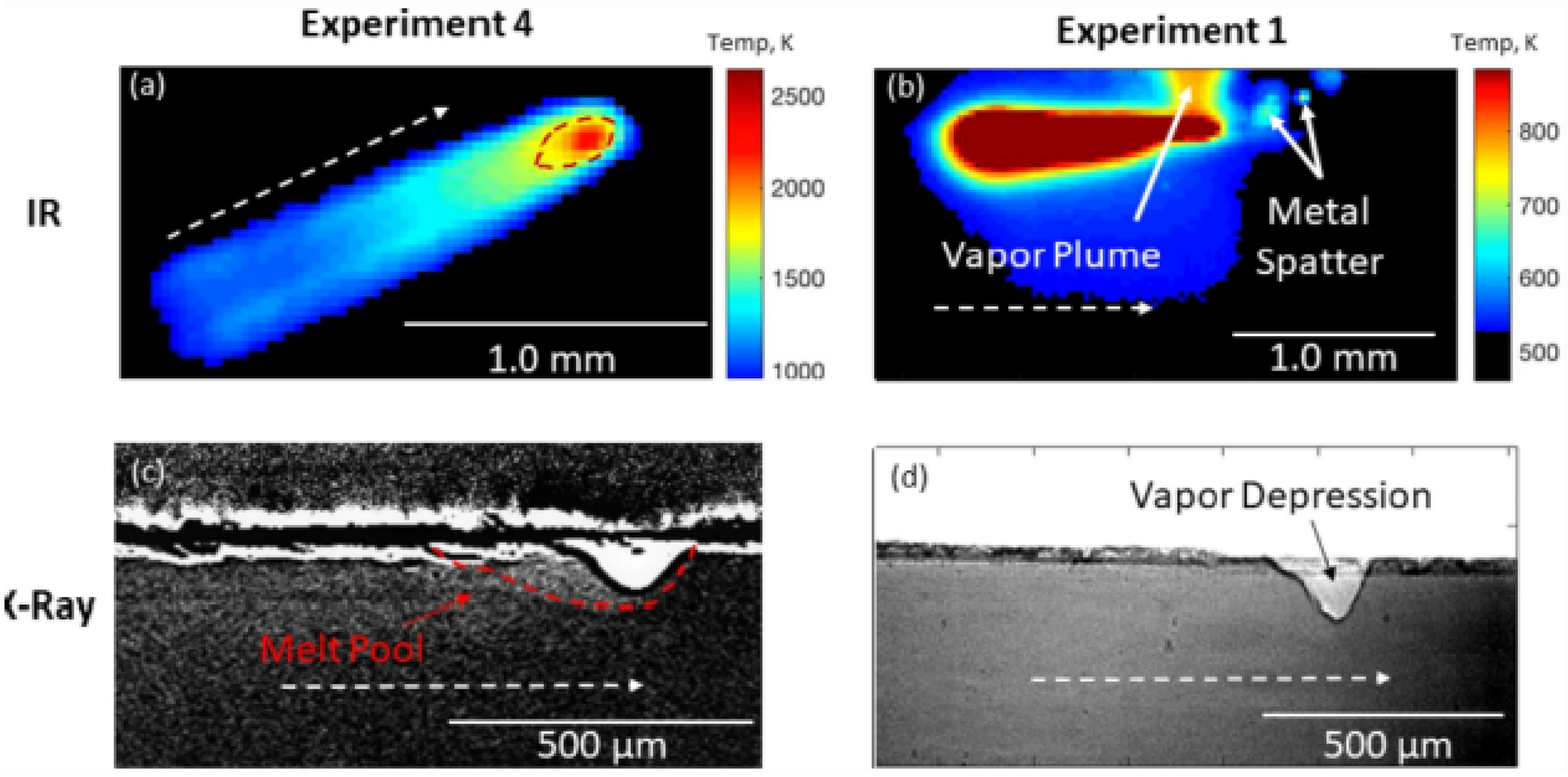
Optical techniques are valuable in the condition monitoring of additive manufacturing processes. They offer a non-contact and non-invasive approach to evaluate different aspects of the printing process and the quality of the printed parts. These techniques cover a wide range of tools, including high-speed cameras, laser scanners, and structured light systems, which capture detailed information about the printing process in real time. Optical monitoring can detect issues such as layer misalignment, warping, and delamination, helping to prevent defects early in the production process. Moreover, the use of optical methods allows for the inspection of the surface finish, dimensional accuracy, and the detection of anomalies that might be challenging to identify using other monitoring techniques. The real-time and high-resolution capabilities of optical techniques make them an essential tool for quality control and process optimization in additive manufacturing. Gould et al. [28] performed the on-site examination of laser powder bed fusion by employing infrared and X-ray imaging cameras simultaneously at high speeds. The use of a high-energy laser beam typically results in elevated temperatures, rapid heating and cooling cycles, and substantial temperature variations, culminating in multiple extremely dynamic physical occurrences that have the potential to introduce defects in the components. In that research, the authors showed a novel method that synchronizes high-speed X-ray imaging with high-speed infrared imaging to explore laser powder bed fusion processes in real time. This approach allowed for the simultaneous observation of multiple phenomena, including visualizing a three-dimensional melt pool, analyzing the vapor plume dynamics, observing the spatter formation, tracking the thermal history, and measuring the point cooling rates (see Figure 2). The combined observation of these dynamic occurrences stands as a crucial factor in understanding the underlying principles of laser powder bed fusion and the comprehensive influence of process variables on the quality of printed parts.
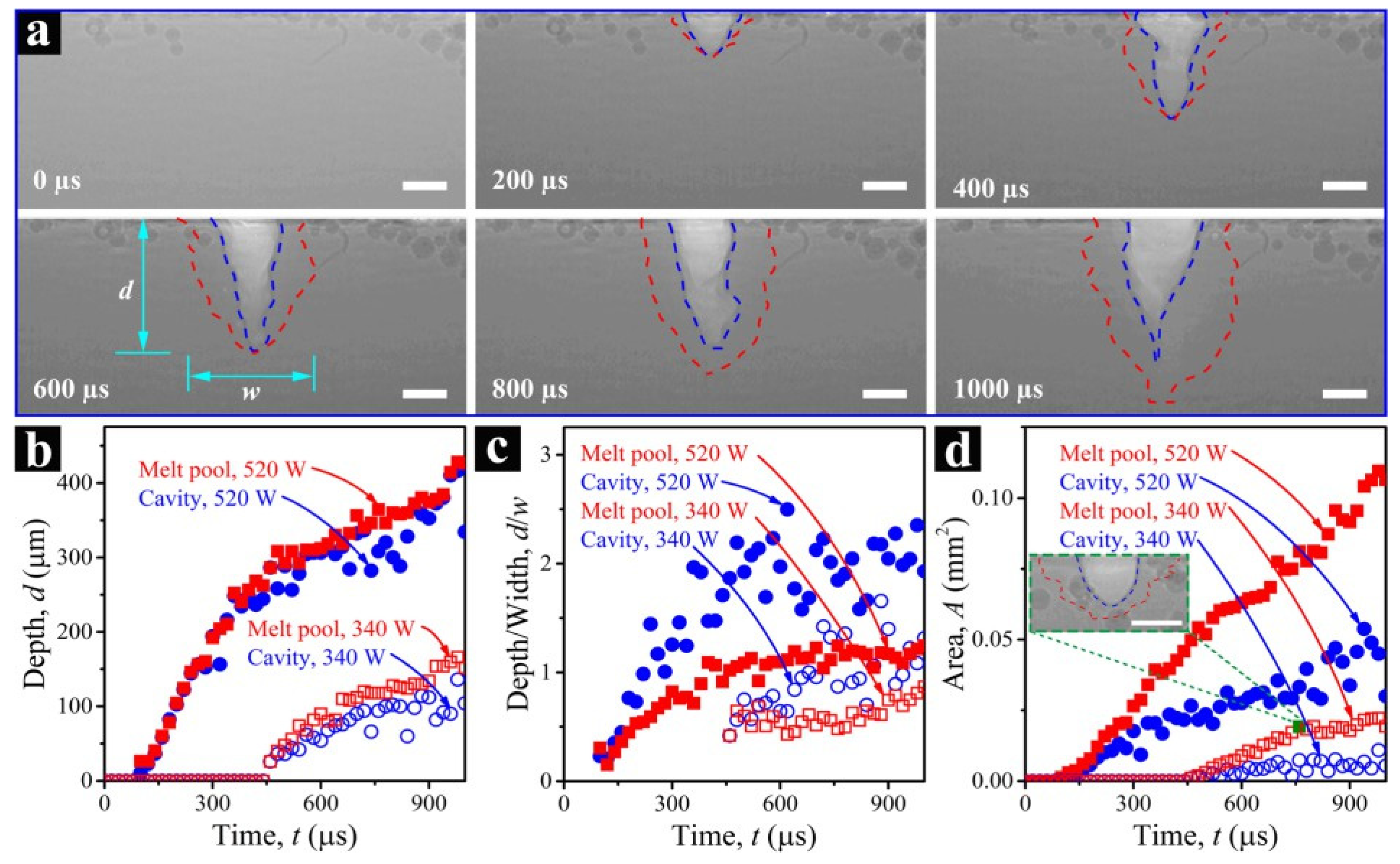
Zhao et al. [29] utilized high-speed synchrotron hard X-ray imaging and diffraction techniques to observe the laser powder bed fusion (LPBF) process of Ti-6Al-4V in real time and on-site. The researchers illustrated that numerous scientifically and technologically crucial phenomena within LPBF, such as the melt pool dynamics, powder ejection, rapid solidification, and phase transformation, can be examined with precise spatial and temporal resolutions. Notably, the formation of keyhole pores was experimentally unveiled with high spatial and temporal resolutions, as shown in Figure 3.
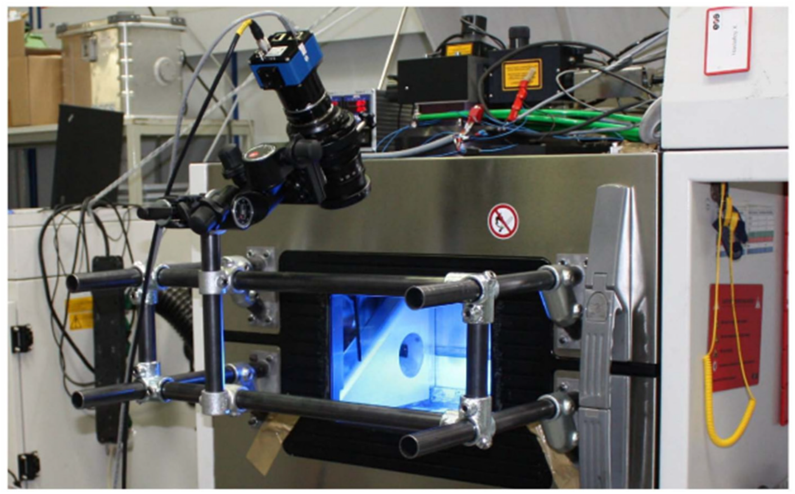
Jacobsmühlen et al. [30] presented a high-resolution imaging system for the inspection of LBM systems, which could be integrated into existing machines without the need for modifying the system’s optical path. This high resolution allows for the detection of any flaws or issues in the part being manufactured, which is crucial for ensuring the quality and structural integrity of the final product. The proposed system could acquire images at a resolution ranging from 25 µm/pixel to 35 µm/pixel, thus enabling the inspection of the melt results and the powder bed in detail (see Figure 4). The integration of this system within the LBM process aimed to enhance process control, enabling the detection of topological errors and assessing the surface quality of the built layers, which could be beneficial for parameter optimization and flaw detection.
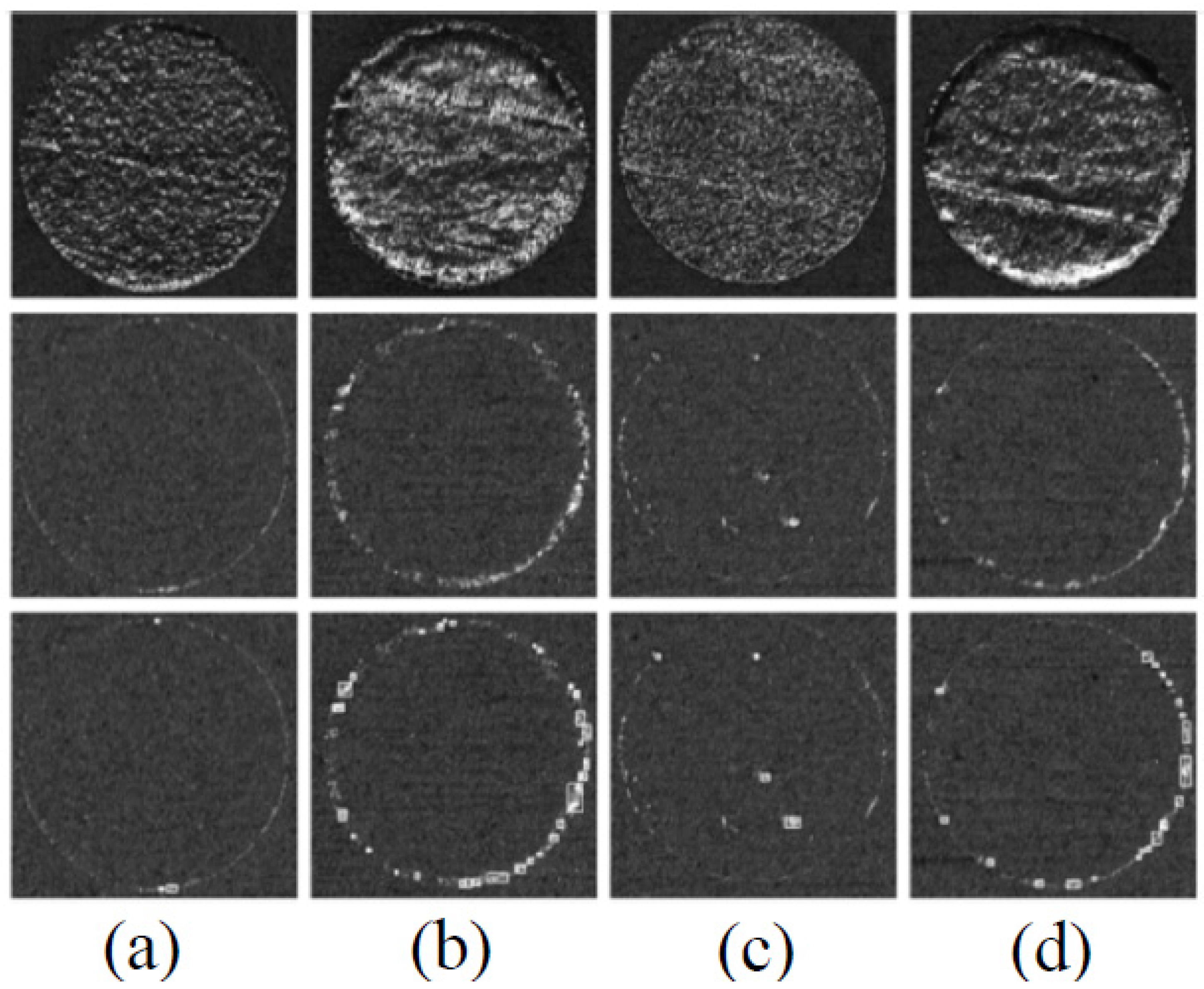
Jacobsmühlen et al. [30] explained the significant impact of laser power settings on the quality of parts produced using Laser Beam Melting (LBM) systems. Through high-resolution imaging, the authors were able to identify the occurrence of super-elevations on the cylinder sample surfaces, as shown in Figure 5 in their publication. In their study, Neef et al. [31] illustrated the innovative use of Low-Coherence Interferometry (LCI) for real-time process monitoring in the SLM process, an additive manufacturing technique. Figure 6 shows the captures of the essence of the measuring range of the LCI sensor across the build platform, illustrating the sensor’s capability to accurately map the topography of the surface.
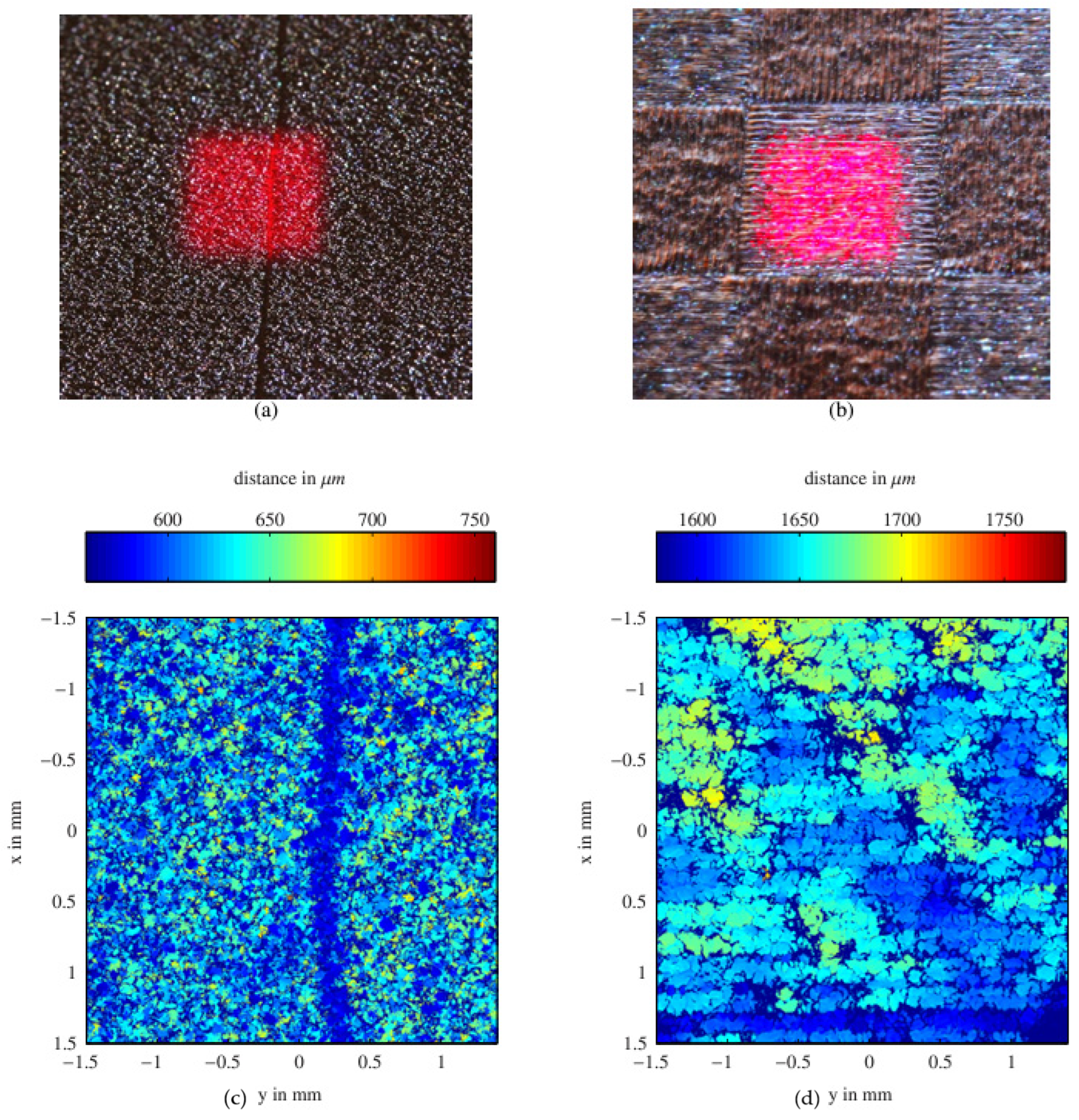
The importance of such a measurement is twofold: it ensures the precise application of each layer and aids in the quick detection of any surface irregularities that could compromise the structural integrity of the final product. As the SLM process relies heavily on maintaining a consistent layer thickness and powder density, the ability to map and measure the surface with such precision is invaluable. Furthermore, Neef et al. [31] focused on the characterization of melted surfaces, where the surface topography of the SLM structures was analyzed. This analysis is depicted in Figure 7 in their paper, which contrasts scans of the powder material surfaces with those of the melted SLM structures. The color-coded depth mapping in this figure clearly demonstrates the surface variations and anomalies which LCI is capable of detecting. Leung et al. [32] used in situ and operando high-speed synchrotron X-ray imaging for the detection of defects and molten pool dynamics in laser additive manufacturing. Their results illustrated in Figure 8 accurately captured the transient phenomena of defect formation and molten pool dynamics within the laser additive manufacturing (LAM) process.
The high-intensity synchrotron radiation utilized in their research allows for the unprecedented observation of the thermophysical behaviors in LAM with acute temporal and spatial resolutions, as detailed in Figure 8. These real-time visualizations provide critical insights into the mechanisms governing the formation of melt tracks, spatter behaviors, and the dynamic evolution of porosity, including the critical phenomena of pore migration, dissolution, and dispersion during the manufacturing process.
In summary, optical methods offer several advantages for condition monitoring in additive manufacturing processes. These techniques provide non-contact measurement capabilities, enabling the assessment of complex geometries without physically touching the surface, thus minimizing the risk of damage to delicate structures. Additionally, optical methods offer a high spatial resolution and precision, allowing for the detailed characterization of surface features and defects. Moreover, optical monitoring techniques, such as photogrammetry and laser scanning, facilitate the real-time monitoring of the manufacturing process, enabling rapid feedback acquisition and quality control. However, these optical methods also have limitations. For instance, they may be sensitive to environmental factors, such as ambient light and temperature variations, which can affect the measurement accuracy. Furthermore, the optical methods may have a limited penetration depth, particularly when inspecting opaque or highly reflective materials, restricting their applicability to certain types of additive manufacturing processes. Overall, while the optical methods offer valuable insights into additive manufacturing processes, careful consideration of their advantages and limitations is essential for effective condition monitoring.

2.2. Thermal Monitoring

Thermal monitoring in additive manufacturing is a critical component in understanding and controlling the complex thermal gradients and cooling rates that significantly affect the microstructure and mechanical properties of the final product. Seppala and Migler [33] have pointed out the details of infrared (IR) imaging, revealing how some systems yield IR signals that intricately reflect material emissivity. When assessing raw IR data across different materials, one must account for the fact that the data provide only a qualitative indication due to this emissivity dependence. This principle is visually captured in Figure 9, where the IR images effectively differentiate the extruder, the printing layer denoted as LP (illustrated in vermilion), the underlying sublayers LP-n (depicted in blue), and the foundational build plate (shown in black).
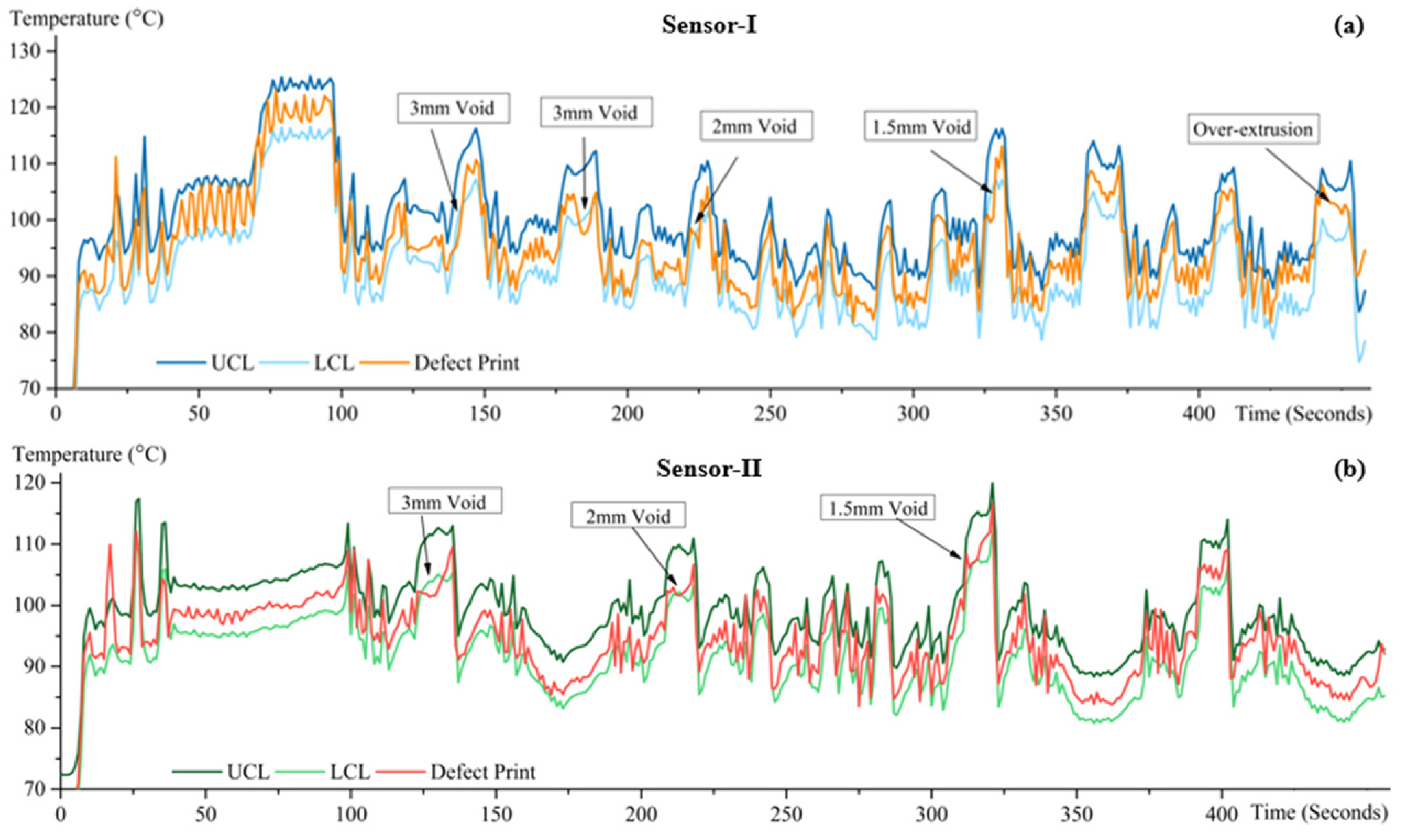
The false-color IR images from Figure 9b–d clearly display the extrusion process with a hot extruder, both active and idle, and a cold state. In Figure 9b, the nozzle’s heat is visible as a dynamic spectrum from red to green, influenced by the melted polymer on the nozzle and uneven heating. The central polymer trail, LP, shows a color shift from red to green with increasing distance from the nozzle, indicating cooling. The LP’s vertical color gradation may reflect an IR intensity gradient due to the extruded material’s shape. Hussein et al. [34] discussed the critical role of in situ infrared temperature sensing in defect detection during FDM additive manufacturing processes. They conducted an in-depth study of how intentional voids of different sizes and under extrusion conditions affect the temperature distribution during the printing of L-shaped samples. The results of their study are shown in Figure 10, showing data from two infrared sensors, along with a control chart demarcating the upper and lower control limits (UCL and LCL) [34]. These limitations were critical for distinguishing the normal process variations from defect-induced anomalies.
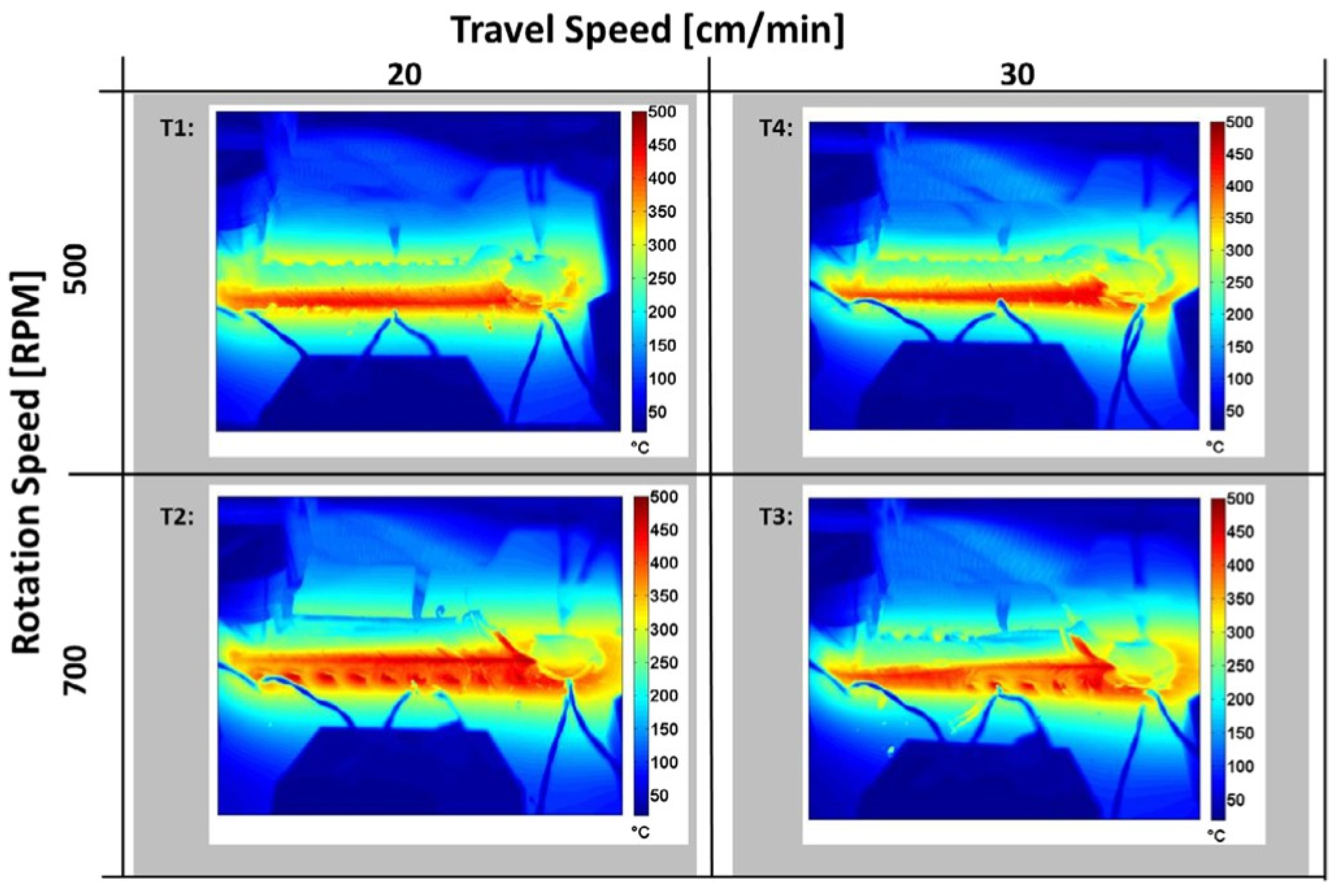
The temperature data provided by Sensor-I in Figure 10 clearly showed the temperature drops corresponding to gaps of 3 mm, 2 mm, and 1.5 mm widths, which are successfully captured in the sensor readings below the LCL. Sensor-II provided conclusive data, detecting similar voids with significant temperature drops. In Figure 11 provided by Serio et al. [35], thermographic maps illustrate the maximum temperatures (Tmax) reached during the Friction Stir Welding (FSW) process of aluminum alloy 5754-H111 sheets. These maps, derived from the analysis of thermal sequences using MATLAB software, displayed Tmax values for each pixel over the course of the welding tests. The thermographic data offered a comprehensive field of temperature information, highlighting the temperature gradients and patterns resulting from varying welding parameters, such as the tool rotation speeds and the travel speeds.
The tests, labeled T1 through T4, represented different combinations of travel speed (in cm/min) and rotation speed (in RPM). For instance, T1 and T4 corresponded to travel speeds of 20 cm/min and 30 cm/min with a rotation speed of 500 RPM, while T2 and T3 denoted tests conducted at 30 cm/min and 20 cm/min, respectively, but with a higher rotation speed of 700 RPM. These variations in the FSW parameters visibly affected the thermal profile of the welds, as evidenced by the different color intensities, representing temperature distributions on the thermographic maps.
As a conclusion, thermal imaging methods offer several advantages for condition monitoring in additive manufacturing processes. These techniques enable the non-contact, remote temperature measurement of surfaces, providing valuable insights into the thermal behavior of printed components during the manufacturing process. Thermal imaging cameras offer a high spatial resolution and sensitivity, allowing for the detection of small temperature variations and hotspots indicative of defects or process anomalies. Moreover, thermal imaging enables the real-time monitoring of temperature distributions, facilitating the rapid identification of issues, such as insufficient heating or cooling, layer delamination, and material inconsistencies. However, the thermal imaging methods also have limitations. Variations in emissivity and surface reflectivity can affect the measurement accuracy, leading to potential inaccuracies in the temperature readings. Additionally, thermal imaging may be limited by line-of-sight constraints and the inability to penetrate through opaque materials, restricting its applicability to certain types of additive manufacturing processes. Despite these challenges, thermal imaging remains a valuable tool for condition monitoring in additive manufacturing, offering unique insights into the thermal performance and integrity of the printed components.

2.3. Acoustics

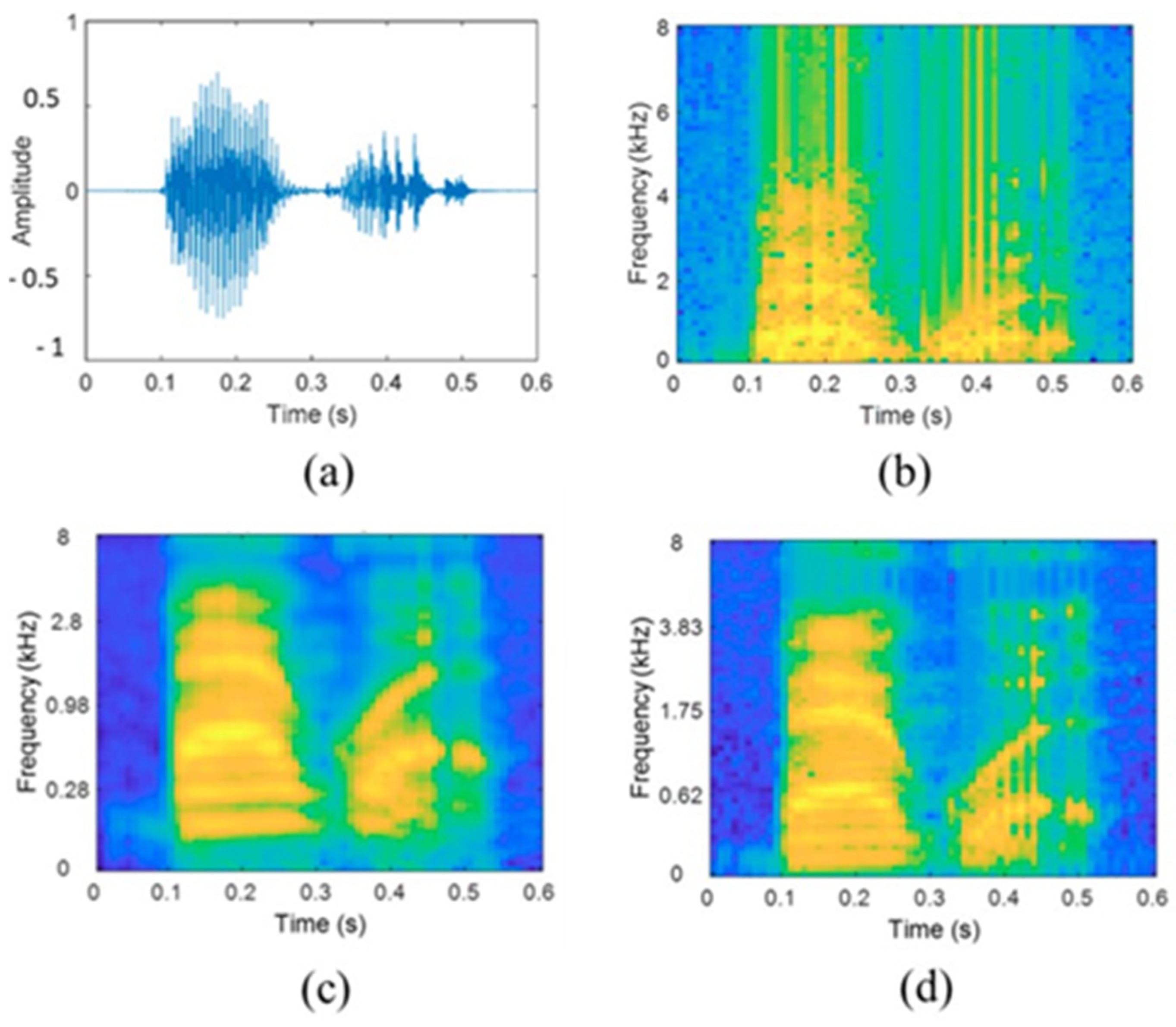
Acoustic monitoring in additive manufacturing refers to a technique where sound or acoustic signals are utilized to assess and monitor the printing process. During additive manufacturing, such as 3D printing, the equipment produces specific acoustic signatures or sounds associated with the deposition and fusion of material layers. By analyzing these acoustic patterns, researchers and manufacturers can gain insights into the quality, consistency, and potential defects of the printed object. The acoustic monitoring method involves using sensors or microphones to capture and interpret the emitted sounds during different stages of the additive manufacturing process (see Figure 12). This approach, however, is not without its challenges. The primary issue is the sensitivity of acoustic signals to background noise and variability in the machine operation conditions, which can complicate the accurate analysis of a machine’s health.
In industrial environments, differentiating between background noise and the actual acoustic signature of machinery is a significant challenge. Jombo and Zhang [36] discussed how advancements in audio analysis for speech and music recognition have led to the development of large acoustic datasets and pre-trained models that could potentially be adapted for industrial sound analysis. For practical applications in machine condition monitoring, Jombo and Zhang [36] illustrated how variations in acoustic image representations can be utilized to classify the sounds that are indicative of machine malfunctions. They discussed several 2D acoustic image representations, such as spectrograms generated from a Short-Time Fourier Transform (STFT) method, Mel spectrograms, and cochlea grams. These representations were effectively used in combination with deep learning models to differentiate between the normal and abnormal machine sounds.
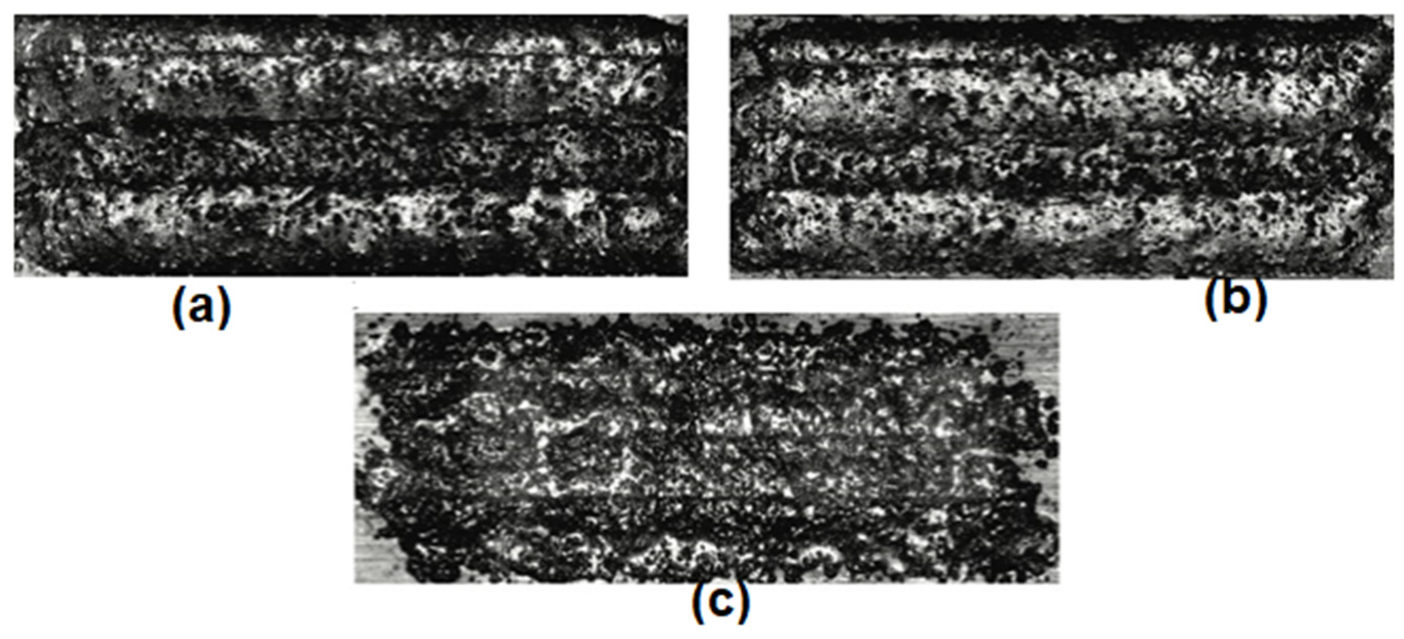
Koester et al. [37] explored the innovative application of in situ acoustic monitoring in the additive manufacturing process. Their paper discussed the importance of in situ acoustic monitoring as a non-destructive evaluation method to identify and analyze the integrity and quality of materials during the additive manufacturing process. By deploying an acoustic monitoring array, the researchers investigated how acoustic data can signal various process conditions, such as the baseline, using a powder only, using a low laser power, and using a low powder flow. These conditions affected the material deposition and, consequently, the final product’s quality. For example, Figure 13 demonstrates micrograph samples from a directed energy deposition process, illustrating variations in the surface characteristics and defects corresponding to different build conditions [34] using the acoustic monitoring method. The images displayed notable differences in the surface morphology and crack development due to variations in the laser power and powder flow.
Raffestin et al. [38] explored in situ ultrasonic monitoring for internal defect detection during the laser powder bed fusion (LPBF) process, which is an advanced additive manufacturing technique. Their study was particularly focused on the use of an ultrasonic (US) system to monitor the formation and evolution of defects within bulk samples as they are manufactured, as depicted in Figure 14. This figure shows the in situ recorded A-scans as a spectrogram, where the amplitude of the ultrasonic signal is plotted on the vertical axis against the number of printed layers on the horizontal axis. The displayed data represent the amplitude of ultrasonic signals for every 10 layers, effectively mapping the internal structural integrity as the part is built. This cumulative depiction corresponds to the final height of the part, showing the progressive nature of the LPBF process.
The spectrogram in Figure 14a illustrates the monitoring of a sample with a 1 mm defect, where the distinct echoes labeled as E1, E2, and E3 show the detection of anomalies at various stages of the build. Likewise, Figure 14b showcases the in situ monitoring of a sample featuring a 2 mm defect, while Figure 14c depicts a 5 mm defect. In both the cases, the amplitude of reflected waves diminishes as the defect size decreases, highlighting the sensitivity of the monitoring system. Millon et al. [39] detailed the application of laser ultrasonics (LU) for real-time quality control in AM processes, particularly for industries like aerospace and healthcare, where precision and reliability are paramount. Figure 15 illustrates B-scan images acquired during scanning, demonstrating the system’s capability to detect notches of different sizes on the forged parts.
Shevchik et al. [40] implemented a Spectral Convolutional Neural Network (SCNN), which was carefully constructed with four convolutional layers, each with a pooling layer behind it. This architecture has been rigorously optimized, achieving a subtle balance between computational complexity and classification efficiency. Their experience found that reducing the number of convolutional layers slightly affected the accuracy of classification, while increasing the number of convolutional layers did not significantly improve performance, but did indeed prolong the training time of the SCNN.
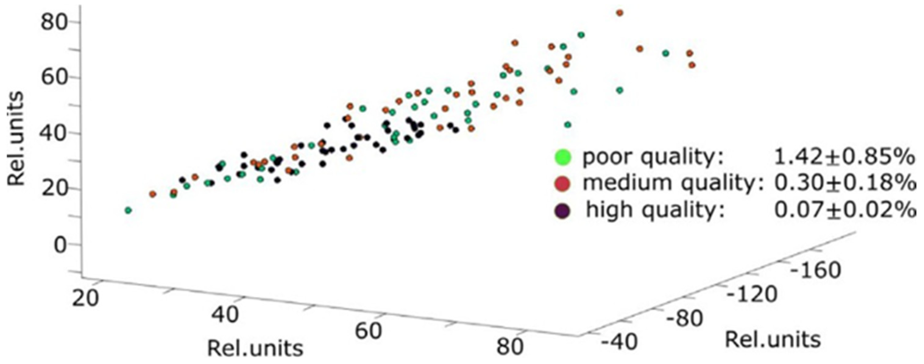
The key aspect of their research involved analyzing the irregularity in the input structure of acoustic features. Shevchik et al. [40] utilized a sparse dataset, where the coordinates of each feature are represented by the relative energy values on the frequency band. This is shown in Figure 16, where the dataset includes thirty features from each defined quality category—poor quality, medium quality, and high quality—each corresponding to a single fragment in the feature space. To extract these complex data into a more interpretable form, they used principal component analysis (PCA) to effectively project the multidimensional feature space into the three-dimensional feature space. This projection not only facilitates clearer visualization, but also emphasizes the heterogeneity of acoustic features, revealing a mixture of attributes across all the quality categories.
As described above, the acoustic methods offer several advantages for condition monitoring in additive manufacturing processes. These techniques utilize sound waves to detect internal defects, structural irregularities, and process anomalies in the printed components. Acoustic monitoring provides non-destructive evaluation capabilities, allowing for the assessment of part integrity, without causing damage to the specimen. Additionally, the acoustic methods offer high sensitivity to defects, enabling the detection of subtle changes in the material properties or structural integrity. Moreover, acoustic monitoring facilitates the real-time detection of defects during the printing process, enabling prompt corrective actions to be taken to prevent the production of faulty components. However, the acoustic methods also have limitations. Environmental noise and background vibrations can interfere with signal detection, potentially reducing the measurement accuracy. Additionally, acoustic monitoring may be limited by the material properties of the printed component, as sound waves can be absorbed or scattered by certain materials, affecting signal transmission and detection. Despite these challenges, the acoustic methods remain a valuable tool for condition monitoring in additive manufacturing, offering unique capabilities for defect detection and quality assurance.

3. Conclusions

This study provides a comprehensive examination of various condition monitoring techniques in additive manufacturing, emphasizing their crucial role in upholding the quality and reliability of AM processes. This review highlights the effectiveness of optical, thermal, and acoustic methods, each presenting distinct advantages and confronting specific challenges. The optical techniques excel in real-time, non-contact inspection, playing a pivotal role in defect detection and quality assurance. Similarly, thermal monitoring, by precisely managing the temperature gradients, profoundly influences the microstructure of AM components, emphasizing its significance in process control. Despite environmental noise challenges, the acoustic and ultrasonic methods exhibit promise in non-intrusive process assessment, supported by advanced data analysis. The integration of these diverse monitoring systems is imperative for a comprehensive grasp and regulation of the intricate AM process.
While condition monitoring methods offer valuable insights into the additive manufacturing process, they are not without limitations. Optical methods, such as photogrammetry and laser scanning, may struggle with certain material properties, such as reflectivity or opacity, limiting their applicability to certain types of additive manufacturing processes. Thermal imaging methods can be affected by variations in emissivity and surface reflectivity, leading to potential inaccuracies in temperature readings. Acoustic methods may be prone to interference from environmental noise and background vibrations, impacting measurement accuracy. Additionally, vibration analysis techniques may struggle to detect defects in complex geometries or small features. Despite these limitations, advancements in sensor technology and data analytics continue to improve the capabilities of condition monitoring methods, offering manufacturers valuable tools for quality assurance and process optimization in additive manufacturing. As AM advances, condition monitoring must evolve as well, incorporating innovations that not only identify, but also predict and pre-empt defects.

Author Contributions

Conceptualization, K.K.; methodology, K.K. and J.C.; formal analysis, K.K., J.C. and H.K.; investigation, K.K., J.C. and H.K.; resources, K.K.; data curation, K.K. and J.C.; writing—original draft preparation, K.K. and J.C.; writing—review and editing, K.K., J.C. and H.K.; visualization, K.K., J.C. and H.K.; supervision, K.K.; project administration, K.K.; funding acquisition, K.K. All authors have read and agreed to the published version of the manuscript.

Funding

The authors would like to acknowledge the RCA fund (RCA U080734) and the Undergraduate Research Opportunity Program (UROP) fund received from the Office of Research University of Michigan.

Conflicts of Interest

The authors declare no conflicts of interest.

References

  1. Hu, Z.; Qin, X.; Li, Y.; Yuan, J.; Wu, Q. Multi-bead overlapping model with varying cross-section profile for robotic game-based additive manufacturing. J. Intell. Manuf. 2020, 31, 1133–1147. [Google Scholar] [CrossRef]
  2. Tapia, G.; Elwany, A. A review on process monitoring and control in metal-based additive manufacturing. J. Manuf. Sci. Eng. 2014, 136, 060801. [Google Scholar] [CrossRef]
  3. Shevchik, S.A.; Masinelli, G.; Kenel, C.; Leinenbach, C.; Wasmer, K. Deep learning for in situ and real-time quality monitoring in additive manufacturing using acoustic emission. IEEE Trans. Ind. Inform. 2019, 15, 5194–5203. [Google Scholar] [CrossRef]
  4. Gibson, I.; Rosen, D.W.; Stucker, B. Additive Manufacturing Technologies: 3D Printing, Rapid Prototyping, and Direct Digital Manufacturing; Springer: Berlin/Heidelberg, Germany, 2014. [Google Scholar]
  5. Ng, W.L.; Goh, G.L.; Goh, G.D.; Sheuan, J.T.J.; Yeong, W.Y. Progress and Opportunities for Machine Learning in Materials and Processes of Additive Manufacturing. Adv. Mater. 2024, e2310006. [Google Scholar] [CrossRef] [PubMed]
  6. Sampedro, G.A.R.; Rachmawati, S.M.; Kim, D.-S.; Lee, J.-M. Exploring machine learning-based fault monitoring for polymer-based additive manufacturing: Challenges and opportunities. Sensors 2022, 22, 9446. [Google Scholar] [CrossRef] [PubMed]
  7. Mahmoud, D.; Magolon, M.; Boer, J.; Elbestawi, M.A.; Mohammadi, M.G. Applications of machine learning in process monitoring and controls of L-PBF additive manufacturing: A review. Appl. Sci. 2021, 11, 11910. [Google Scholar] [CrossRef]
  8. Chen, H.-Y.; Lin, C.-C.; Horng, M.-H.; Chang, L.-K.; Hsu, J.-H.; Chang, T.-W.; Hung, J.-C.; Lee, R.-M.; Tsai, M.-C. Deep learning applied to defect detection in powder spreading process of magnetic material additive manufacturing. Materials 2022, 15, 5662. [Google Scholar] [CrossRef] [PubMed]
  9. Zhang, B.; Li, Y.; Bai, Q. Defect formation mechanisms in selective laser melting: A review. Chin. J. Mech. Eng. 2017, 30, 515–527. [Google Scholar] [CrossRef]
  10. Gong, H.; Rafi, K.; Gu, H.; Starr, T.; Stucker, B. Analysis of defect generation in Ti–6Al–4V parts made using powder bed fusion additive manufacturing processes. Addit. Manuf. 2014, 1–4, 87–98. [Google Scholar] [CrossRef]
  11. Weingarten, C.; Buchbinder, D.; Pirch, N.; Meiners, W.; Wissenbach, K.; Poprawe, R. Formation and reduction of hydrogen porosity during selective laser melting of alsi10mg. J. Mater. Process. Tech. 2015, 221, 112–120. [Google Scholar] [CrossRef]
  12. Tang, M.; Pistorius, P.; Beuth, J. Prediction of lack-of-fusion porosity for powder bed fusion. Addit. Manuf. 2017, 14, 39–48. [Google Scholar] [CrossRef]
  13. Phuc, L.; Seita, M. A high-resolution and large field-of-view scanner for in-line characterization of powder bed defects during additive manufacturing. Mater. Des. 2019, 164, 107562. [Google Scholar] [CrossRef]
  14. Jacobsmuhlen, J.Z.; Kleszczynski, S.; Witt, G.; Merhof, D. Detection of elevated regions in surface images from laser beam melting processes. In Proceedings of the IECON 2015—41st Annual Conference of the IEEE Industrial Electronics Society, Yokohama, Japan, 9–12 November 2015; p. 15753163. [Google Scholar]
  15. Mumtaz, K.; Hopkinson, N. Top surface and side roughness of inconel 625 parts processed using selective laser melting. Rapid Prototyp. J. 2009, 15, 96–103. [Google Scholar] [CrossRef]
  16. Li, R.; Liu, J.; Shi, Y.; Wang, L.; Jiang, W. Balling behavior of stainless steel and nickel powder during selective laser melting process. Int. J. Adv. Manuf. Technol. 2012, 59, 1025–1035. [Google Scholar] [CrossRef]
  17. Lin, X.; Zhu, K.; Fuh, J.Y.H.; Duan, X. Metal-based additive manu-facturing condition monitoring methods: From measurement to control. ISA Trans. 2022, 120, 147–166. [Google Scholar] [CrossRef] [PubMed]
  18. Jia, X.; Zhao, M.; Di, Y.; Yang, Q.; Lee, J. Assessment of data suitability for machine prognosis using maximum mean discrepancy. IEEE Trans. Ind. Electron. 2018, 65, 5872–5881. [Google Scholar] [CrossRef]
  19. Kwon, O.; Kim, H.; Ham, M.; Kim, W.; Kim, G.; Cho, J.; Kim, N.; Kim, K. A deep neural network for classification of melt-pool images in metal additive manufacturing. J. Intell. Manuf. 2020, 31, 375–386. [Google Scholar] [CrossRef]
  20. Liu, Y.; Guo, L.; Gao, H.; You, Z.; Ye, Y.; Zhang, B. Machine vision-based condition monitoring and fault diagnosis of machine tools using information from machined surface texture: A review. Mech. Syst. Signal Process. 2022, 164, 108068. [Google Scholar] [CrossRef]
  21. Nguyen, V.-C.; Le, M.-Q.; Mogniotte, J.-F.; Capsal, J.-F.; Cottinet, P.-J. Extrusion-based 3D printing of stretchable electronic coating for condition monitoring of suction cups. Micromachines 2022, 13, 1606. [Google Scholar] [CrossRef] [PubMed]
  22. Akhavan, J.; Manoochehri, S. Sensory data fusion using machine learning methods for in-situ defect registration in additive manufacturing: A review. In Proceedings of the 2022 IEEE International IOT, Electronics and Mechatronics Conference (IEMTRONICS), Toronto, ON, Canada, 1–4 June 2022. [Google Scholar]
  23. Kempen, K.; Thijs, L.; Vrancken, B.; Buls, S.; Humbeeck, J.V.; Kruth, J.-P. Producing crack-free, high density m2 hss parts by selective laser melting: Pre-heating the baseplate. In Proceedings of the 2013 International Solid Freeform Fabrication Symposium, Austin, TX, USA, 12–14 August 2013; pp. 1–9. [Google Scholar]
  24. Lin, W.; Shen, H.; Fu, J.; Wu, S. Online quality monitoring in mate- rial extrusion additive manufacturing processes based on laser scanning technology. Precis. Eng. 2019, 60, 76–84. [Google Scholar] [CrossRef]
  25. Ye, D.; Zhu, K.; Fuh, J.Y.H.; Zhang, Y.; Soon, H.G. The investigation of plume and spatter signatures on melted states in selective laser melting. Opt. Laser Technol. 2019, 111, 395–406. [Google Scholar] [CrossRef]
  26. Griffiths, S.; Tabasi, H.G.; Ivas, T.; Maedar, X.; De Luca, A.; Zweiacker, K.; Wrobel, R.; Jhabvala, J.; Loge, R.E.; Leinenbach, C. Combining alloy and process modification for microcrack mitigation in an additively manufactured ni-base superalloy. Addit. Manuf. 2020, 36, 101443. [Google Scholar]
  27. Liu, C.; Law, A.C.C.; Roberson, D.; Kong, Z. Image analysis based closed loop quality control for additive manufacturing with fused filament fabrication. J. Manuf. Syst. 2019, 51, 75–86. [Google Scholar] [CrossRef]
  28. Gould, B.; Wolff, S.; Parab, N.; Zhao, C.; Lorenzo-Martin, M.C.; Fezzaa, K.; Greco, A.; Sun, T. In situ analysis of laser powder bed fusion using simultaneous high-speed infrared and X-ray imaging. JOM 2021, 73, 201–211. [Google Scholar] [CrossRef]
  29. Zhao, C.; Fezzaa, K.; Cunningham, R.W.; Wen, H.; De Carlo, F.; Chen, L.; Rollett, A.D.; Sun, T. Real-time monitoring of laser powder bed fusion process using high-speed X-ray imaging and diffraction. Sci. Rep. 2017, 7, 3602. [Google Scholar] [CrossRef] [PubMed]
  30. Jacobsmühlen, J.Z.; Kleszczynski, S.; Schneider, D.; Witt, G. High resolution imaging for inspection of laser beam melting systems. In Proceedings of the IEEE Instrumentation and Measurement Technology Conference, Minneapolis, MN, USA, 6–9 May 2013. [Google Scholar] [CrossRef]
  31. Neefa, A.; Seyda, V.; Herzog, D.; Emmelmann, C.; Schonleber, M.; Kogel-Hollacher, M. Low coherence interferometry in selective laser melting. Phys. Procedia 2014, 56, 82–89. [Google Scholar] [CrossRef]
  32. Leung, C.L.A.; Marussi, S.; Atwood, R.C.; Towrie, M.; Withers, P.J.; Lee, P.D. In situ X-ray imaging of defect and molten pool dynamics in laser additive manufacturing. Nat. Commun. 2018, 9, 1355. [Google Scholar] [CrossRef] [PubMed]
  33. Seppala, J.; Migler, K. Infrared thermography of welding zones produced by polymer extrusion additive manufacturing. Addit. Manuf. A 2016, 12, 71–76. [Google Scholar] [CrossRef] [PubMed]
  34. Hossain, R.; Lewis, J.; Moore, A. In situ infrared temperature sensing for real-time defect detection in additive manufacturing. Addit. Manuf. 2021, 47, 102328. [Google Scholar] [CrossRef]
  35. Serio, L.; Palumbo, D.; Galietti, U.; Filippis, L.D.; Ludovico, A. Monitoring of the friction stir welding process by means of thermography. Nondestruct. Test. Eval. 2016, 31, 371–383. [Google Scholar] [CrossRef]
  36. Jombo, G.; Zhang, Y. Acoustic-based machine condition monitoring—Methods and challenges. Eng 2023, 4, 47–79. [Google Scholar] [CrossRef]
  37. Koester, L.W.; Taheri, H.; Bond, L.J.; Faierson, E.J. Acoustic monitoring of additive manufacturing for damage and process condition determination. In AIP Conf. Proc. 2019, 2102, 020005. [Google Scholar]
  38. Raffestin, M.; Domashenkov, A.; Bertrand, P.; Faverjon, P.; Courbon, C. Ultrasonic diagnostic for in situ control in metal additive manufacturing. Measurement 2023, 206, 112244. [Google Scholar] [CrossRef]
  39. Millon, C.; Vanhoye, A.; Obaton, A.-F.; Penot, J.-D. Development of laser ultrasonics inspection for online monitoring of additive manufacturing. Weld. World 2018, 62, 653–661. [Google Scholar] [CrossRef]
  40. Shevchik, S.; Kenel, C.; Leinenbach, C.; Wasmer, K. Acoustic emission for in situ quality monitoring in additive manufacturing using spectral convolutional neural networks. Addit. Manuf. 2018, 21, 598–604. [Google Scholar] [CrossRef]
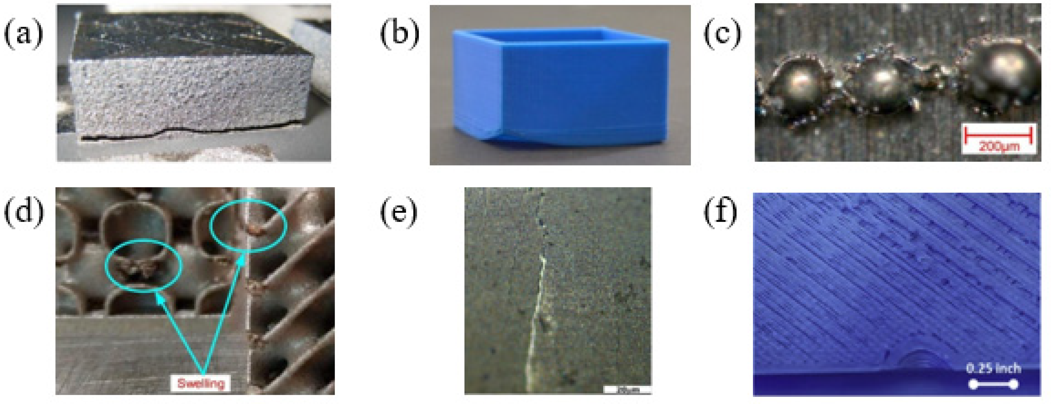
Figure 1. Typical examples of defects in additive manufacturing showing: macro-cracks (a) [23], warping (b) balling (c) [24], swelling (d) [25], micro-cracks (e) [26], and an under-filled part (f) [27].
Jmmp 08 00095 g001
Figure 2. Aligned and calibrated infrared (IR) and X-ray images reveal distinctive features discernible through the synergistic application of these characterization methods. In each image, the direction of laser scanning is denoted by a dashed white arrow. (a,c) illustrate that the processed X-ray image contrast can be used to identify the melt-pool length, which can then be correlated to the top-view IR image to mark out the melt-pool morphology on the surface plane parallel with the X-ray beam. (c) X-ray images were divided by the first frame of this image series to highlight the contrast of the melt pool. (b,d) illustrate that filter 0 of the IR camera can be used to view the vapor plume, a feature that is not visible in X-ray imaging [28].
Jmmp 08 00095 g002
Figure 3. Dynamic changes in the melt pool during the laser powder bed fusion process of Ti-6Al-4V [29].
Jmmp 08 00095 g003
Figure 4. The camera setup in front of the LBM machine [30]. The modular tube construction enables flexible positioning with an adjustable height, position, and distance from the door.
Jmmp 08 00095 g004
Figure 5. From top to bottom: cylinder sample surface image, next powder layer, and detected super-elevations. (a) Reference, (b) laser power +40%, (c) laser power −40%, and (d) hatch distance −40% [30].
Jmmp 08 00095 g005
Figure 6. Scanning range along the y-axis of the build platform [31].
Jmmp 08 00095 g006
Figure 7. Surface scan of (a) powder material, (b) the SLM structure, (c) powder material, and (d) the SLM structure [31].
Jmmp 08 00095 g007
Figure 8. Time-series radiographs acquired during LAM of an Invar 36 single-layer melt track (MT1) under P = 209 W, v = 13 mm/s, and LED = 16.1 J/mm [32].
Jmmp 08 00095 g008
Figure 9. Illustration and false color IR images of 3D printing process. From left to right, (a) an illustration, (b) extrusion, a (c) hot extruder/no extruder, and (d) a cold extruder are shown (the color scale is linear) [33].
Jmmp 08 00095 g009
Figure 10. +/3σ control chart comparing defected print temperature data with control limits [34]. (a) Sensor-I and (b) Sensor-II.
Jmmp 08 00095 g010
Figure 11. Maps of maximum temperatures assessed for each test [35].
Jmmp 08 00095 g011
Figure 12. Acoustic image representations [36]. (a) acoustic input (b) spectrogram of acoustic input (c) cochleagram of acoustic input (d) Mel spectrogram of acoustic input.
Jmmp 08 00095 g012
Figure 13. Stitched micrograph sample images of each build condition showing differing surface characteristics and surface breaking cracks. (a) Baseline condition, (b) surface roughness influenced by a low-laser-power setting, and (c) significant cracks and rips generated in a low-powder-flow scenario [37].
Jmmp 08 00095 g013
Figure 14. In situ monitoring of samples with internal designed defects [38].
Jmmp 08 00095 g014
Figure 15. B-scans issues from scanning [39].
Jmmp 08 00095 g015
Figure 16. Projection of the acoustic features into a 3D feature space using principal component analysis (PCA) [40].
Jmmp 08 00095 g016
Disclaimer/Publisher’s Note: The statements, opinions and data contained in all publications are solely those of the individual author(s) and contributor(s) and not of MDPI and/or the editor(s). MDPI and/or the editor(s) disclaim responsibility for any injury to people or property resulting from any ideas, methods, instructions or products referred to in the content.