Article

Development of Hot-Wire Laser Additive Manufacturing for Dissimilar Materials of Stainless Steel/Aluminum Alloys

1
Graduate School of Advanced Science and Engineering, Hiroshima University, Higashi-Hiroshima 739-0046, Japan
2
Mitsubishi Electric Corporation, Tokyo 100-8310, Japan
*
Authors to whom correspondence should be addressed.
J. Manuf. Mater. Process. 2024, 8(3), 93; https://doi.org/10.3390/jmmp8030093
Submission received: 28 March 2024 / Revised: 26 April 2024 / Accepted: 29 April 2024 / Published: 30 April 2024

Abstract

:
The formation of brittle intermetallic compounds (IMCs) at the interface between dissimilar materials causes considerable problems. In this study, a multi-material additive manufacturing technique that employs a diode laser and the hot-wire method was developed for stainless steel/aluminum alloys. An Al-Mg aluminum alloy filler wire (JIS 5183-WY) was fed on an austenitic stainless-steel plate (JIS SUS304) while varying the laser power and process speed and using paste-type flux and flux-cored wire. The effects of laser power and process speed on phenomena during manufacturing and IMC formation were investigated. Finally, the wall-type multilayer specimens were fabricated under optimized conditions. The suppression of IMC formation to a thickness of less than 2 μm was achieved in the specimens, along with a high interfacial strength of over 120 MPa on average.

1. Introduction

Additive manufacturing (AM) is a novel manufacturing method that offers ample advantages in terms of manufacturing complex parts, reducing manufacturing time and saving resources by using less material, in contrast to conventional methods, since the target product can be molded directly. AM for metal materials uses the powder bed fusion method, in which powder is laid down and bonded by (i) sintering or melting, (ii) the direct-energy deposition method, in which the material is supplied in the form of a powder or wire and molded by an external heat source such as a laser, and (iii) the wire-arc AM method, in which arc welding technology is used. The fusion method has been the focus of studies and the one put into practical use [1,2,3,4]. Because process speeds are slow, the present AM technology is used for manufacturing high-value-added products that are produced in small batches under high-mix low-volume production. Several research and development projects have targeted nickel-based alloys, stainless steels, titanium alloys, and aluminum alloys, which are common materials used for high-value-added products [5,6,7].
Another characteristic of AM is its capability to combine multiple materials for manufacturing. Numerous studies have been conducted concerning the multi-materialization of AM with the expectation of reducing weight and improving performance [8,9,10,11]. Some of these studies sought to control the mechanical properties of compacts, for example, by joining different materials such as Ti/Al or Fe/Ti or by combining materials with different properties (e.g., ductility) [12,13,14]. Sun et al. [15] used wire-arc additive manufacturing (WAAM) to fabricate aluminum alloys on stainless-steel base materials. The temperature between molding passes was significantly affected by the growth of IMC and succeeded in fabricating molds with a shear strength of 95 MPa when the temperature between passes was 100 °C. Karim et al. [16] have investigated multi-material fabrication using cold metal transfer (CMT) to fabricate aluminum on a stainless-steel base. The relationship between IMC thickness and bond strength at the interface of dissimilar materials was determined by varying the heat input. Finally, a joint strength of 130 MPa was obtained at low heat input.
Other methods of joining Fe-Al dissimilar materials in the solid state and IMC formation have also been studied. Xu et al. [17] performed ultrasonic spot welding of low-carbon steel DC04 and high-strength aluminum alloys AA6111 and AA7075, varying the joining time from 0.2 to 2.4 s. The results showed that Fe2Al5 grew rapidly in the initial stage of welding and FeAl3 grew after 0.7 s of welding. In addition, the IMC thickness in the joining of AA7075 was thicker than that in the joining of AA6111, indicating that the Zn contained in AA7075 may affect the thickness of the IMC.
In the case of dissimilar material joining by Friction Stir Welding (FSW), Tanaka et al. [18] fabricated an FSW butt joint with two 3 mm thick plates of A1100 and mild steel, changed the joining temperature by changing the tool rotation speed, and investigated the growth mechanism of IMC using the diffusion equation. The growth mechanism of IMC can be expressed by the diffusion equation as in the case of diffusion bonding. Three factors affect the formation of IMC: fresh surface, stored strain, and plastic flow, and the diffusion constant of FSW is higher than that of other joining methods. However, it is concluded that IMC formation is suppressed because the time to stay at the temperature of IMC formation is short in the joining process. Various types of IMC have been reported to be formed in FSW, such as FeAl, Fe3Al, etc. It has been reported that elements such as Cr and Ni act as diffusion hindering and suppress the growth of IMC, so the thickness of IMC and the type of IMC formed depend on the target material [19,20,21]. The relationship between joint strength and IMC thickness is that higher strengths are produced with thinner IMC, unless there is an unbonded region [22]. Therefore, improving joint strength requires controlling the thickness of the IMC.
In recent years, laser brazing has been used to join Fe/Al. Developed mainly for the automotive industry, joining steel sheets up to 2 mm thick and 6000-series aluminum alloys have been investigated [23,24,25,26,27]. Fluxes are often used in Fe/Al brazing to improve wettability and to remove oxide films on the surface. The main mechanisms by which fluxes remove oxide films are (i) chemical removal, (ii) electrochemical removal, and (iii) mechanical removal [28]. Zhu et al. [29] proposed that the removal of oxide film in chloride fluxes occurs when F- ions penetrate into the interstitial sites of the Al2O3 crystal lattice, causing local cracks and weakening of the adhesion between the oxide film and the Al substrate, and then Zn2+ ions penetrate into the film through the cracks and chemically react with the Al substrate to form Zn deposits under the film and Al and the oxide film is removed by breaking the bond between the film and the Al substrate. KAlF4-K2 and AlF6 fluxes are widely used as the main fluxes. However, when the base metal contains Mg, a high-melting-point compound is formed and the activity of the flux is reduced; fluxes such as CsF-AlF3 are used when brazing materials contain Mg [30,31]. By adjusting the chemical compositions of the flux and filler wire, high-quality joints with an IMC thickness of approximately 1 µm have been produced through laser brazing [32].
Multi-material AM of aluminum alloys on a stainless steel base plate was studied in this paper. The main heat source used in AM is a diode laser, which has a low energy density and a high degree of freedom in spot shape. In addition, the hot-wire method was adopted, in which the filler wire is heated to near its melting point through electric-current heating before insertion into a molten pool. Because the wire is heated to just below the melting point, the hot-wire method allows the quantity of the weld metal to be increased without relying on an external heat input. Many studies combining this method with AM show improvements in manufacturing efficiency [33,34,35,36,37,38,39]. Hot-wire laser AM is an AM method classified as laser wire DED, and its accuracy is lower than that of powder-based AM methods such as Powder Bed Fusion (PBF). Therefore, finishing by cutting is required in the final stage. However, the amount of cutting can be reduced by near-net-shape molding.
Two methods of fabrication of dissimilar materials were attempted: one was applying flux on a stainless steel substrate and the other was the use of a flux-cored wire (FCW), in which flux is filled inside the wire. For flux-coated fabrication, the influence of laser spot size on flux activation was investigated, and for fabrication using FCW, the influence of laser power on the fabrication phenomenon was investigated. Based on the results of these experiments, multilayer moldings were fabricated under optimized fabrication conditions, and strength evaluations were conducted.

2. Materials and Methods

2.1. Material

JIS SUS304 (Produced by JFE Steel Co., Fukuyama, Japan), austenitic stainless steel with a thickness of 15 mm, was used as the base metal and was coated with a chloride flux (neis F19, produced by Neis Co., Hyogo, Japan). The flux was mixed at a 2:1 ratio of water and flux, applied to the base metal, and dried in a drying oven twice before conducting the experiments. JIS A5183-WY (Produced by UACJ Co., Saitama, Japan) with a diameter of 1.2 mm, an Al-Mg aluminum alloy wire, was used as the additive filler wire. For the first layer on the SUS304 plate, FCW (neis S4Le Cs-based flux, produced by Neis Co., Hyogo, Japan) with a diameter of 1.2 mm was used as the additive filler wire. The results of the cross-sectional analysis of FCW by scanning electron microscope (SEM, Hitachi SU-1510) are shown in Figure 1. The average area of the sheath section was 1.1 mm2 and the average area of the flux section was 0.12 mm2 for the 10 cross-sections analyzed. For the strength evaluation, the JIS A5183-WY wire was used for the second and subsequent layers in the multilayer manufacturing. The chemical compositions of the base metal and filler wires are listed in Table 1 and Table 2.

2.2. Experimental Procedure

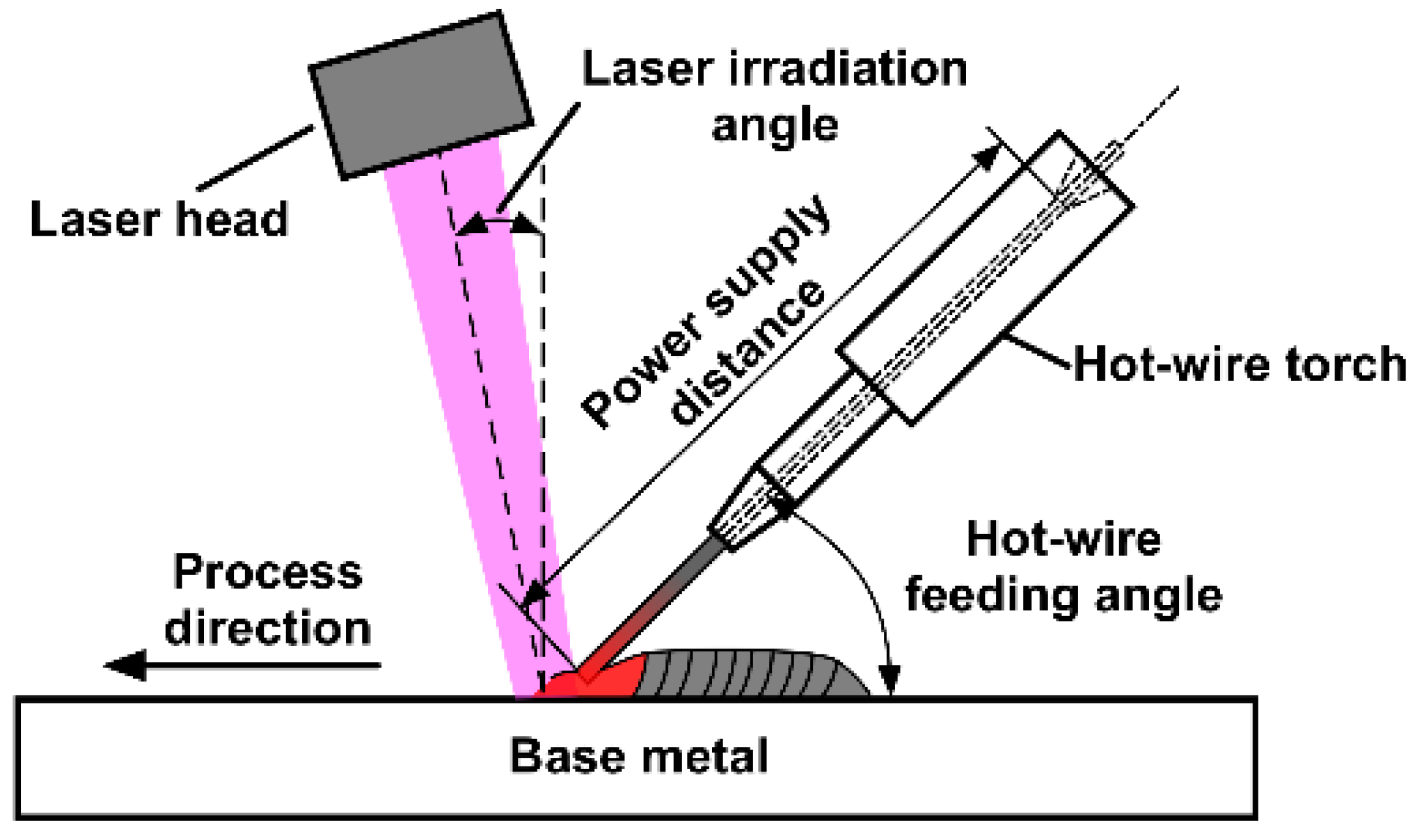
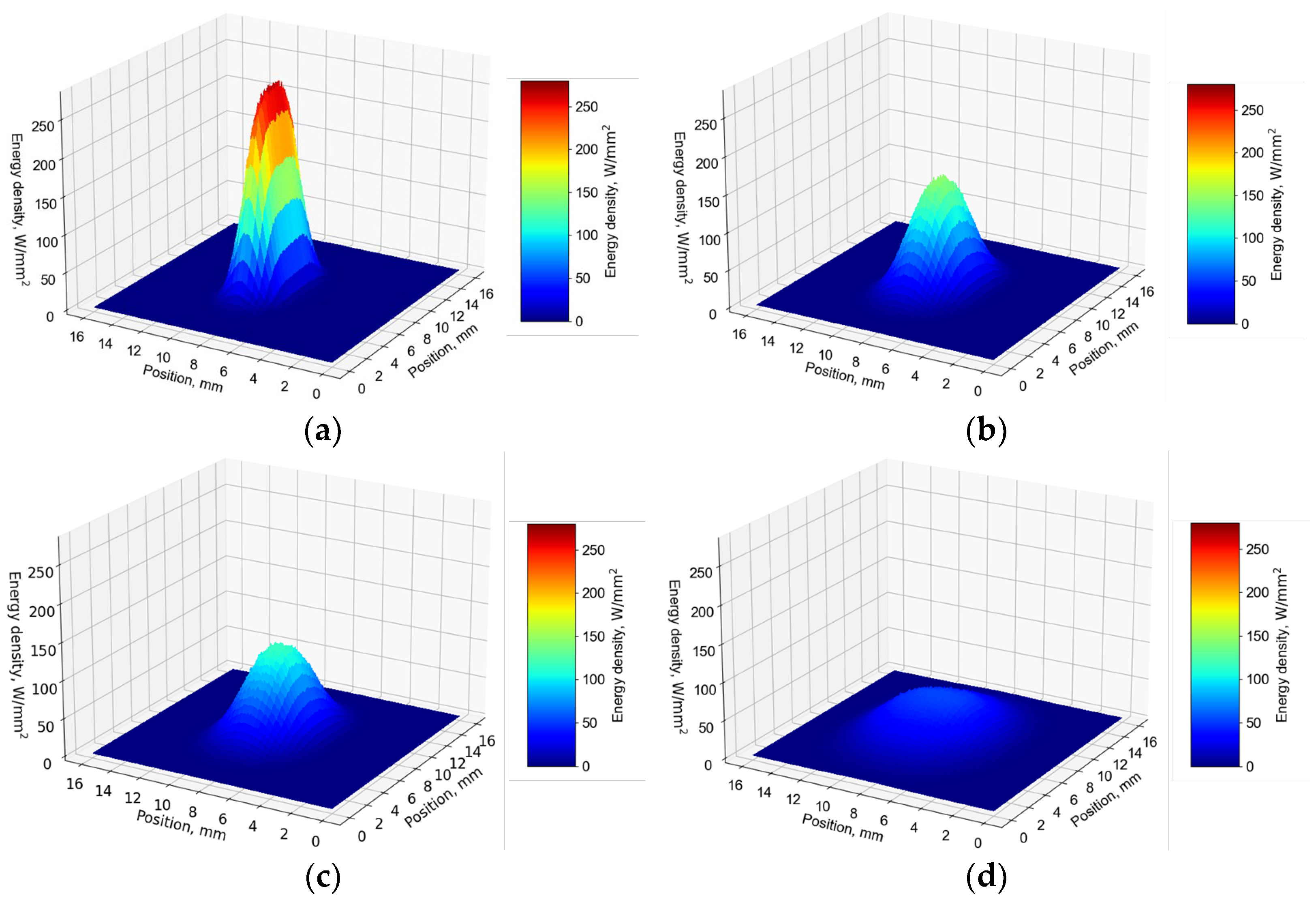
For the experimental set-up of the hot-wire laser AM process (see Figure 2), the first layer was a stainless steel/aluminum alloy joining layer. The filler wire was fed from the rear in the process direction. In the second and subsequent layers for the multilayer fabrication, the filler wire was fed from the front in the process direction. The hot wire current was set at the limit current value at which fusing does not occur so that the wire is heated to near the melting point. In all experiments, the power supply distance was 70 mm, and the hot-wire feeding angle was 45 degrees. A Laserline LDF 6000-40 diode laser was used for the laser. The laser output from the Fiber core 1000 μm was focused by a collimator lens (100 mm) and a focus lens (200 mm), and a rectangular laser spot of 2.5 mm × 5.0 mm was formed by using a homogenizer. Figure 3 shows the energy density distribution of the laser at just focus, defocus +15 mm, defocus +20 mm, and defocus +40 mm at 3.0 kW for a 2.5 mm × 5.0 mm rectangular laser spot.
The pre-melting conditions for the flux are known to have a significant influence on joining phenomena in hot-wire laser brazing [40]. Therefore, the size effects of the laser spot on flux activation were investigated first. The experiments involved altering the defocusing length to +40 mm, +20 mm, and +15 mm to confirm the flux activation under these conditions (Column (a) in Table 3). From the flux-coated experimental results obtained, conditions were established that reduced the processing speed and improved the process stability (Column (b) in Table 3). The IMC thickness of the fabricated specimens was quantified using an SEM.
During fabrication with the FCW, the activation condition of the flux also has a considerable effect on the wetting spread of the filler material, as with flux coating. However, the flux activation phenomenon may differ between the two methods because the flux supplied from the molten pool must be activated in front of the molten pool when applied. Therefore, flux activation performed with the FCW was employed under a laser-beam power of 4.7, 5.0, 5.5, and 6.0 kW at a fixed process speed of 1.5 m/min (Table 3(c)).
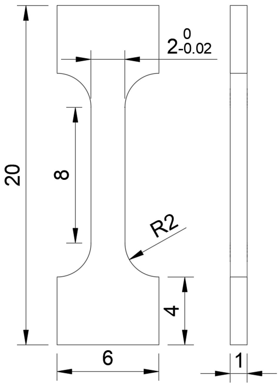
From the experimental results obtained through fabrication using a flux-coated wire and with an FCW, various multilayer samples were manufactured. The multilayer samples comprising nine layers had a total thickness of over 12 mm using the processing conditions for a flux-coated wire and for an FCW (see Columns (a) and (b) in Table 4). Using images from the high-speed camera of the second layer through to the ninth, the laser-beam power was adjusted appropriately for each layer to keep the molten pool size constant. Five tensile test specimens (Figure 4) were cut from each manufactured specimen, and their tensile strengths were evaluated. Although this specimen shape is not in the ASTM or JIS standards, similar small specimens have been used in previous studies [16], and a strength comparison with the previous study can be performed. After testing, the fracture surfaces were observed under SEM and energy-dispersive X-ray (EDX) spectroscopy.
High-speed camera imaging was performed during all hot-wire laser processing. The FPS was set to 500 and the shutter speed was set to 1/2500 s. To capture clear images, laser illumination with a beam of wavelength 808 nm was used and a bandpass filter that matched this wavelength was attached to the lens.

3. Results and Discussion

3.1. Effect of Laser Spot Size on Flux Melting Phenomena

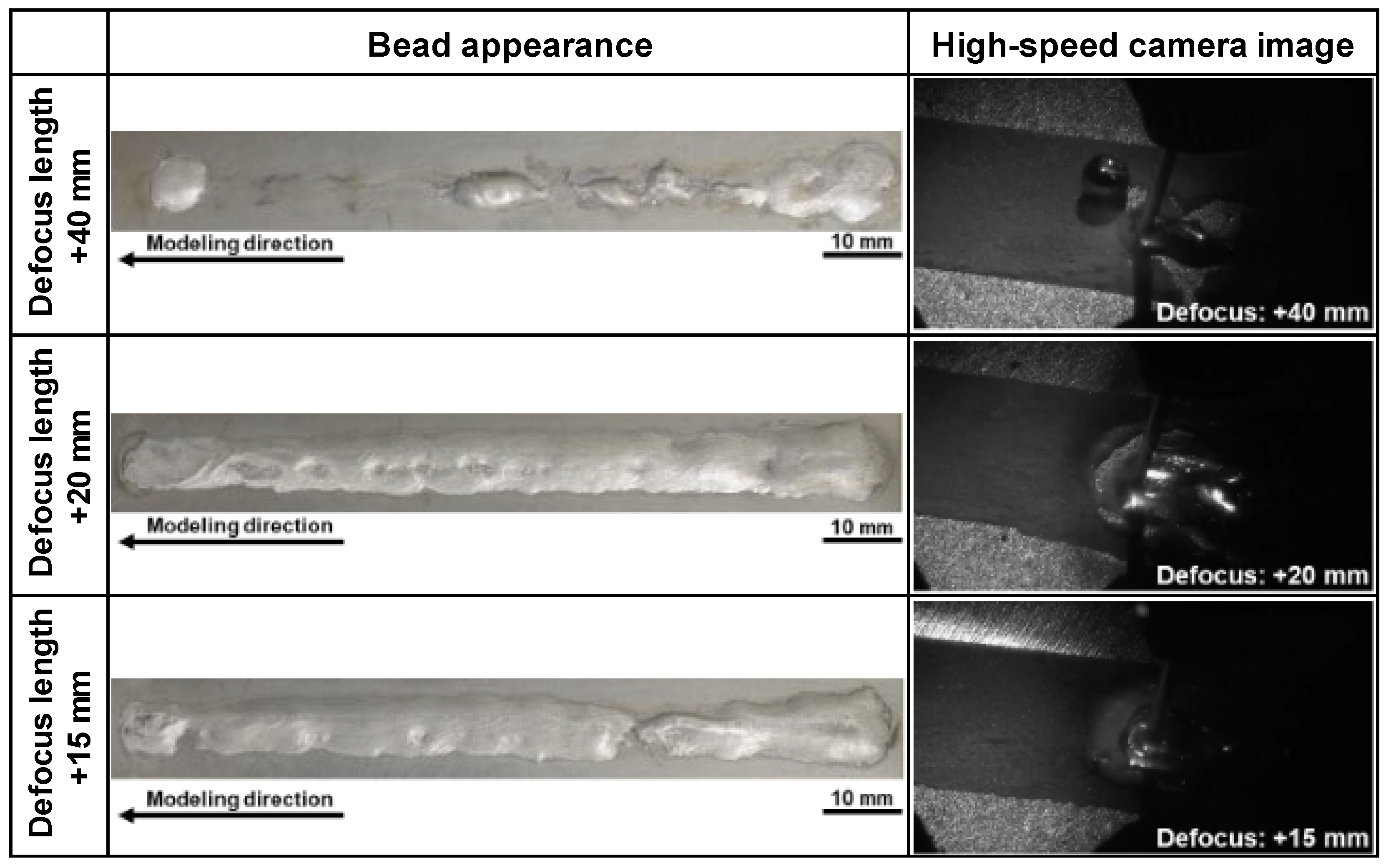
In high-speed images taken during fabrication, beading is evident at the front of the molten pool under the flux-coated-type conditions (Figure 5). Defocusing lengths of +40 mm and +20 mm resulted in an excessive flux pre-melting; areas where molten metal has spread and flux has activated do not coincide. Under +40 mm defocusing length conditions, the flux is activated before the wire feeding position, and molten aluminum blobs form at the filler wire tip. In contrast, under +15 mm defocusing length conditions, the laser-illuminated area and the area where molten metal spreads are seen to coincide, and a stable flux melting and activation phenomenon is evident. From the above results, we note that if the laser-illuminated area is excessively wide, the flux disappears before the molten metal spreads, and stable bead formation does not occur. Therefore, the optimum laser spot size is determined by balancing the wire feeding rate and laser-beam power to ensure stable processing.
From the above experimental results, the defocusing length was set to +15 mm and the processing speed was reduced to stabilize the molding. Figure 6 shows images of beads obtained under slower processing speeds and high-speed images at the front of the molten pool during manufacturing. Stable bead shapes are observed, and instability of bead width (Figure 5) is not evident. In addition, from the SEM image of a cross-section (Figure 7), the thickness of the IMC layer across the whole width of the stainless steel/aluminum interface is suppressed to approximately 2 μm, even though the slower process speed of 1.0 m/min was employed.

3.2. Laser Power Effect of Molding Phenomena Using FCW

Figure 8 shows images of beads appearing under FCW-type conditions and high-speed images at the front of the molten pool during manufacturing under different laser-beam powers. With a low power of 4.7 kW, defects caused through insufficient molten metal flow behind the wire can be seen at the center of the bead. The reason is that the molten pool shrinks and the speed of solidification also quickens. In addition, the spread of wetting near the end of the bead becomes unstable. Defect formation at the bead center observed with this low-power set-up was resolved under both 5.0 kW and 5.5 kW power conditions. Spreading of stable wetting and presence of a bead were achieved from beginning to end. However, at the higher laser-beam power of 6.0 kW, the bead shape is unstable because the wire fuses near the starting point of the bead. Fumes from the location of the laser spot were also observed in high-speed images during processing, indicating that the laser power was excessive. This type of fuming occurs when a rapid temperature rise occurs even under protective gas (e.g., excessive laser power, surface condition change of the molten pool due to wire fusion, and flux evaporation).
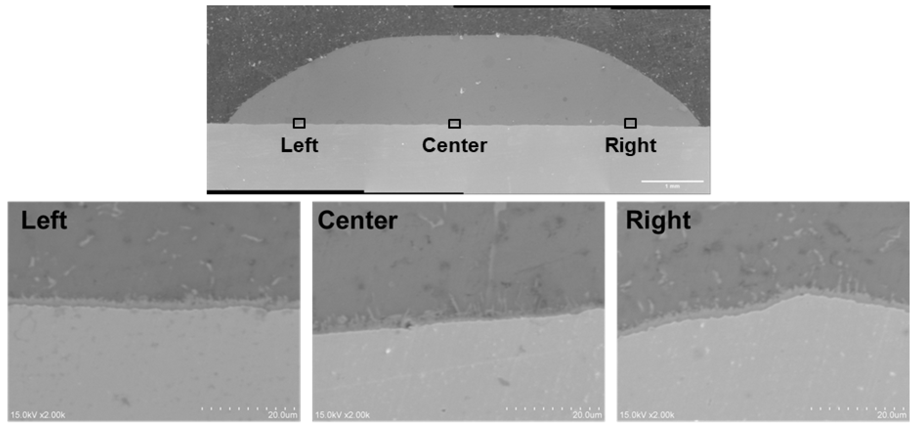
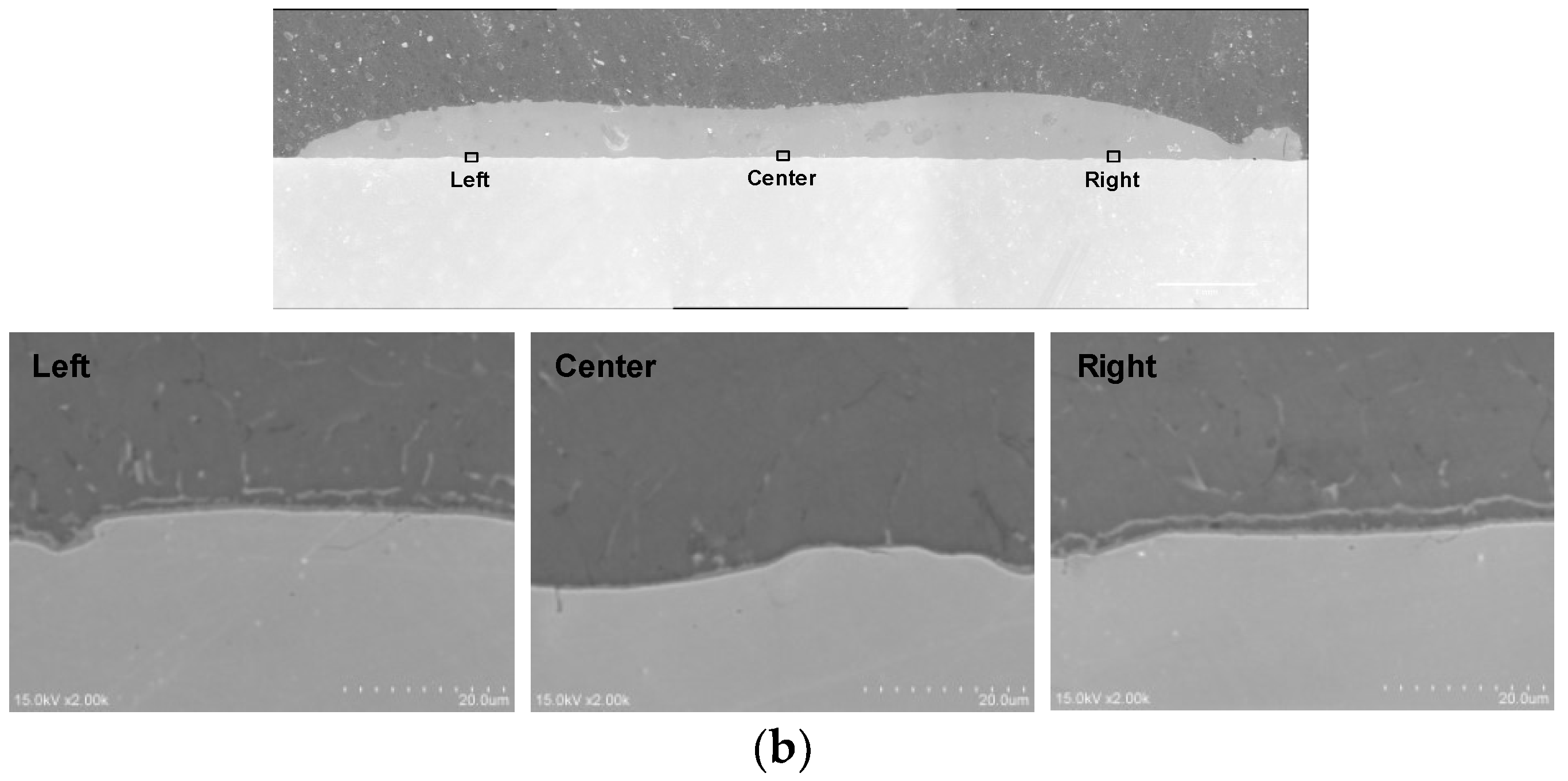
For the 4.7 kW and 6.0 kW laser power set-ups, cross-sections were cut from a stable area of fabricated beads and observed under SEM. With both set-ups (Figure 9), the IMC layer was thin, with a thickness of approximately 2 µm at the edges and less than 1 µm at the centers of beads. This difference in IMC thickness can be explained by the difference in laser-beam illumination of the base metal in the center, where the molten metal is pushed from the wire feed, thereby reducing the direct illumination of the base metal.
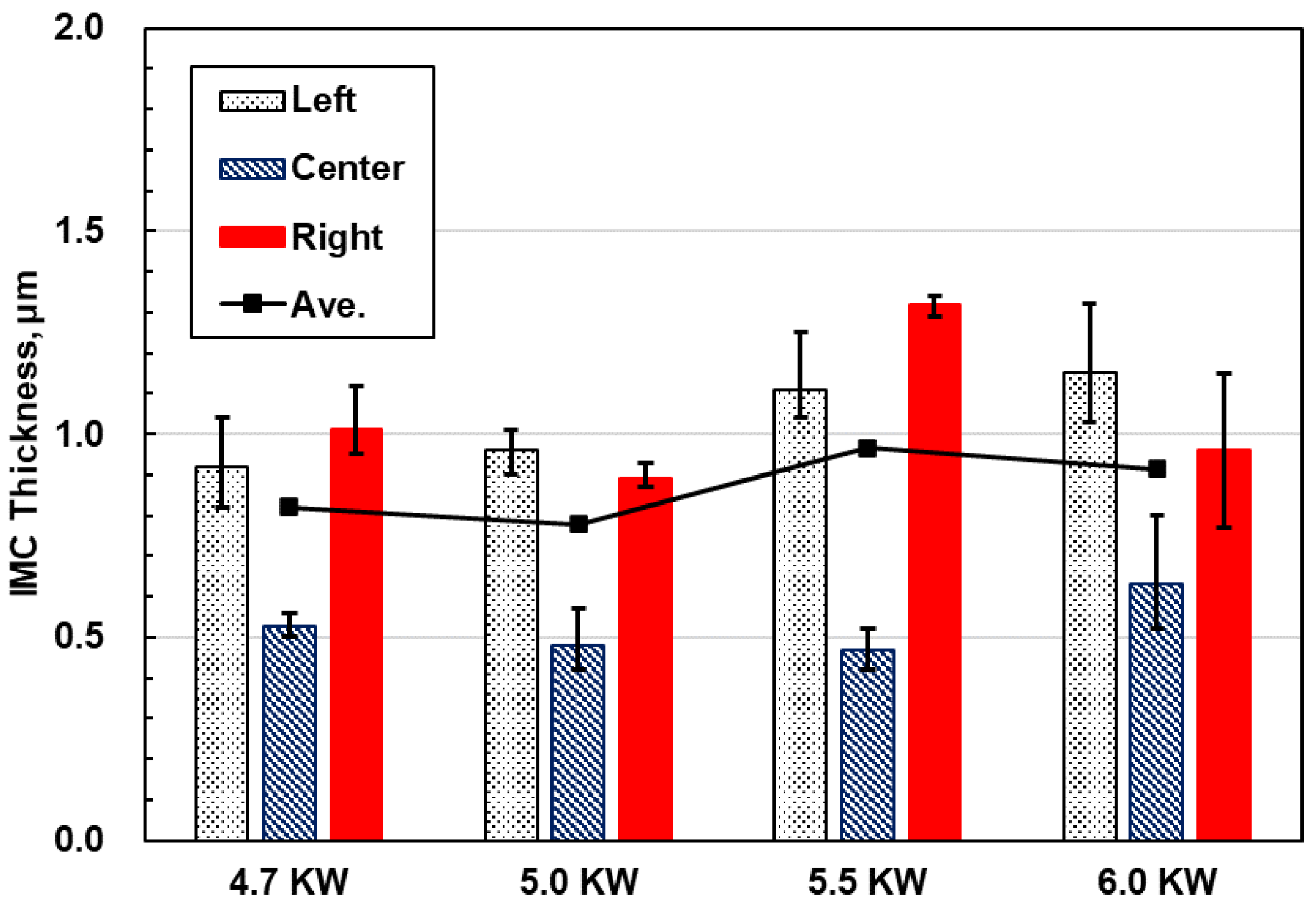
From the experimental results, sufficient laser power and molten pool size are necessary to avoid defect formation because the flow of molten metal around the center of the bead is important. The IMC thickness at the bonding interface was measured by SEM at three locations each at the center of the molding body, 2 mm from the left edge of the molding body and 2 mm from the right edge of the molding body under the conditions of 4.7 kW to 6.0 kW (Figure 10). No significant difference was observed. Therefore, laser power does not have a significant effect on IMC thickness in this process.

3.3. Strength Evaluation and Fracture Surface Observation of Dissimilar Stainless Steel/Aluminum Alloy Interfaces

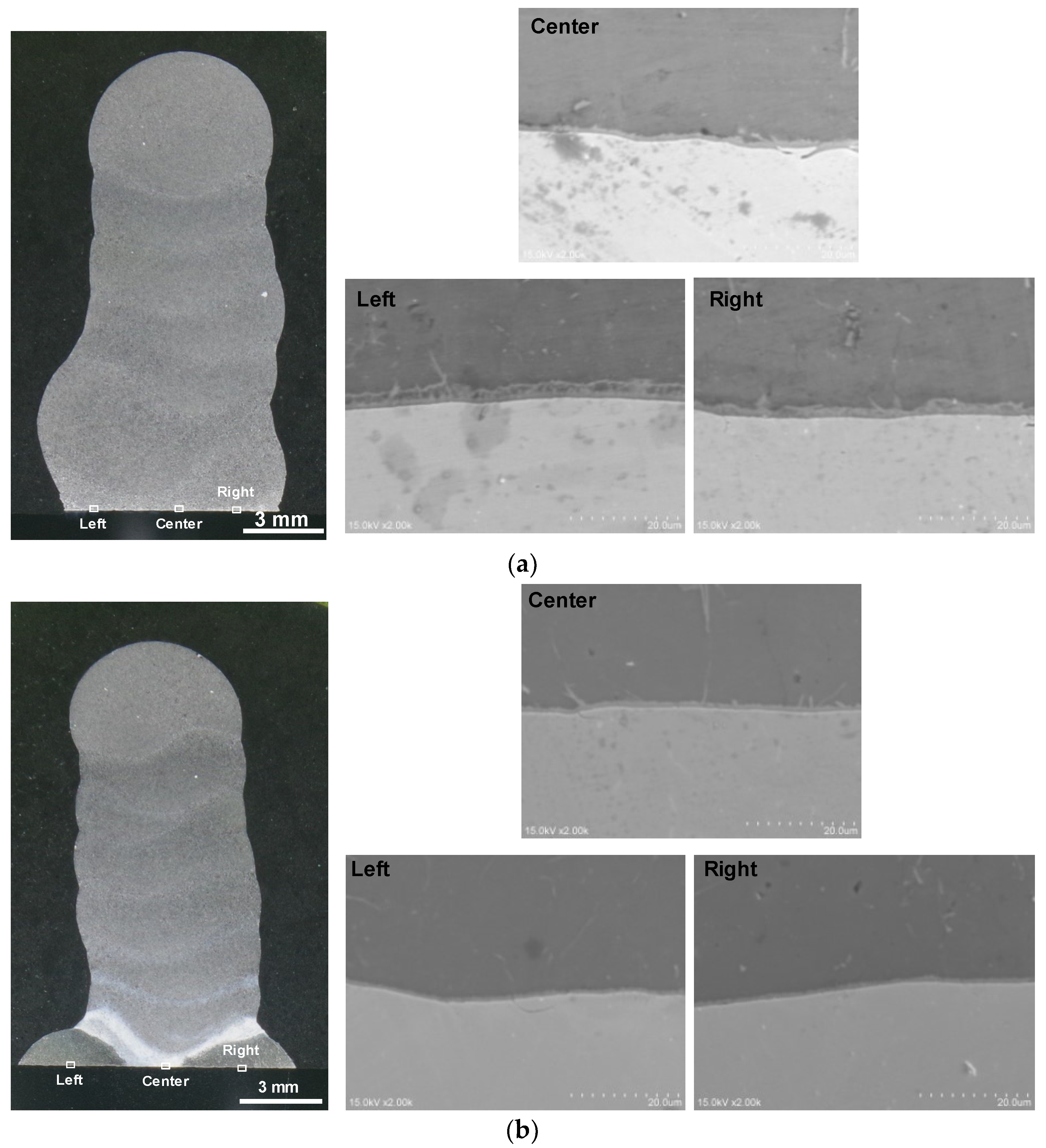
Multilayered samples were fabricated based on the experimental results of the flux-coated-type and FCW-type set-ups. Cracks and other defects were not observed in the fabricated samples. Cross-sectional and SEM images of the stainless steel/aluminum alloy interface of each specimen after etching with Tucker’s acid were obtained (Figure 11). The IMC layer thickness of the flux-coated-type specimen was approximately 2 μm, with the variation in thickness being small. Similarly, the IMC layer thickness in the FCW-type specimen was also small, at approximately 1 µm, and the variation was quite small. The secondary heat input to the interface of the stainless steel/aluminum alloy during second-layer processing was notably quite small. Therefore, the IMC layer thicknesses remained small at 1–2 μm without significant IMC growth.
Figure 12 shows the results of EDX line analyses at the stainless steel/aluminum alloy interfaces of both samples. From these results for the flux-coated-type specimen, Fe-Al IMCs such as Fe2Al5 are formed. In contrast, for the FCW-type specimen, Si is concentrated in the IMC layer at the interface, and Fe9Al2Si2 IMCs are formed at the interface of the molding body fabricated by FCW. The Fe-Al-Si IMC is known to have a lower enthalpy of formation than the Fe-Al IMC and tends to grow preferentially because of the presence of Si in the FCW [41].
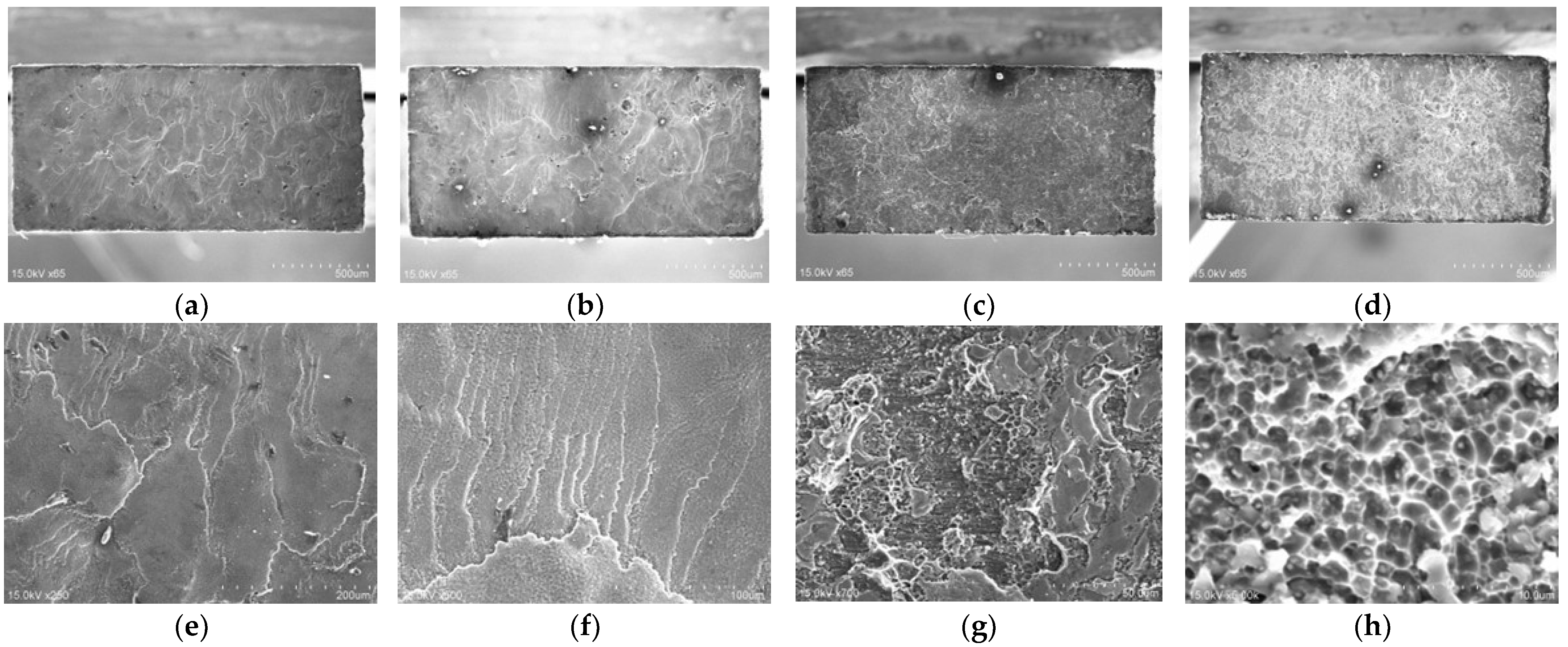
Table 5 and Table 6 show the tensile test results for both flux-coated-type and FCW-type specimens. All specimens had fractured at the stainless steel/aluminum alloy interface. Although the tensile strength of both the flux-coated and FCW specimens varied, a high tensile strength of over 125 MPa was obtained on average. To investigate the cause for the difference in tensile strength among the specimens, fracture surface observations were performed on four typical specimens: Nos. 1 and 3 for the flux-coated-type specimens and Nos. 2 and 5 for the FCW-type specimens.
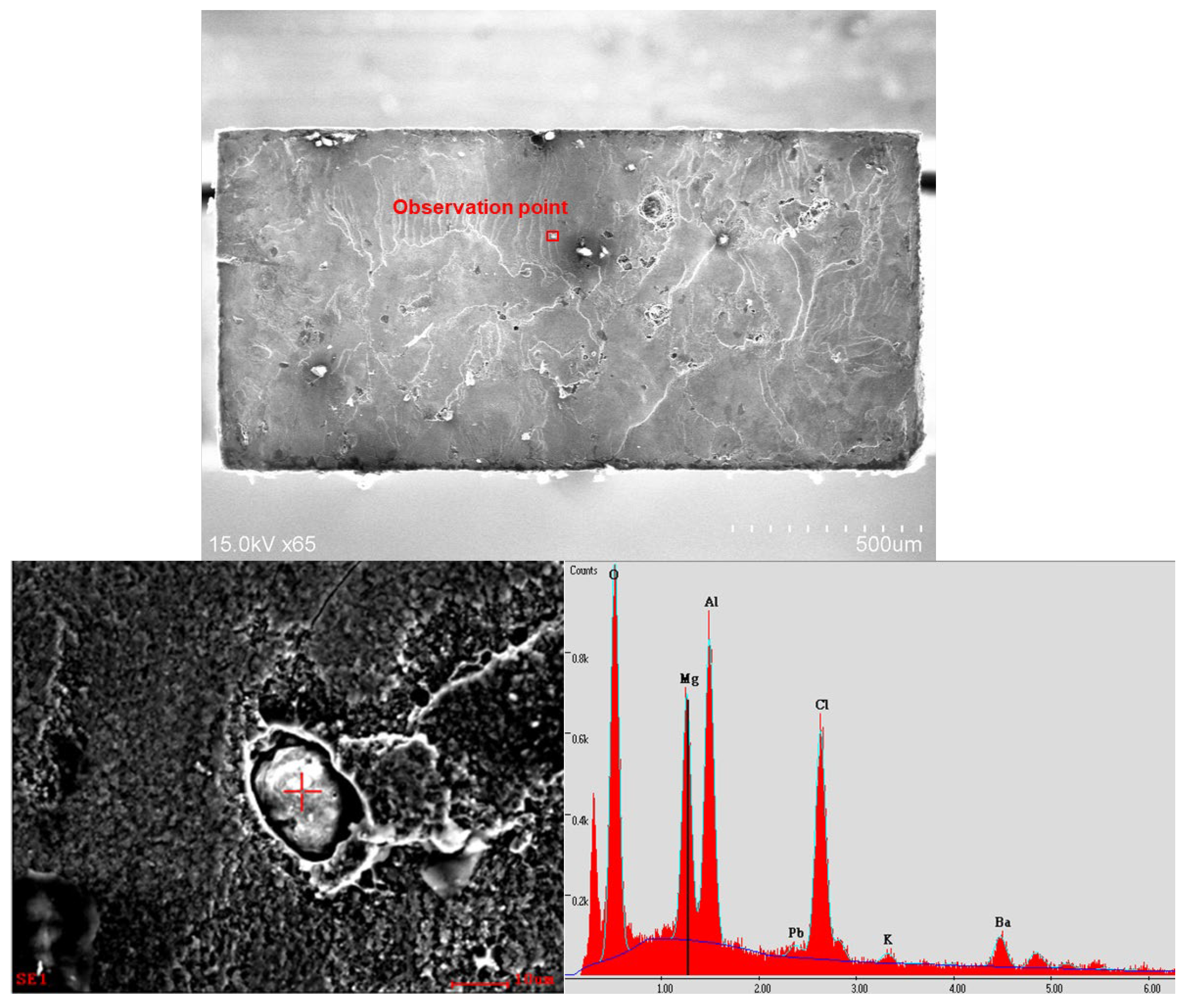
In SEM images of the fracture surfaces of each specimen (Figure 13), all surfaces show no visible plastic deformation, even under high tensile strengths, but dimples can be seen on the surfaces in the SEM images. This is probably because low-strength aluminum is plastically constrained by high-strength stainless steel, resulting in a ductile instability fracture without large visible plastic deformation. Such fracture surfaces have been observed in friction welding, which enables strong bonding [42]. In contrast, no dimples were observed in the specimen with low tensile strength, and particles were found on the fracture surface. EDX point analyses were conducted on the particles (Figure 14). Flux components such as K and Cl were detected in the defects. Oxides of other elements were also detected.
From these results, the cause for the decrease in the bond strength of the stainless steel/aluminum alloy interface was confirmed to be due to flux incursion and oxide particle formation that occurred during the processing of the first layer. The large variation among the specimens can be attributed to the volume of flux incursion. The formation of oxides of particles is relatively large compared with the cross-sectional size of the specimen used in the tensile test (Figure 4). Higher average tensile strength with lower variation is expected to be achieved by reducing the volume of flux incursion and oxide particle formation. Importantly, tensile tests of specimens having larger cross-sectional sizes need to be conducted.

4. Conclusions

In this study, austenitic stainless steel SUS304 was used as base plates, and dissimilar-material laminate molding of stainless steel–aluminum was undertaken using two methods in which aluminum was molded through either directly coating the base material with flux or using FCW. The results of this study are summarized as follows.
  • The aluminum was molded by flux coating on a stainless-steel base plate and using a 2.5 × 5.0 mm laser spot in the laser optics. To confirm the influence of laser spot size on molding phenomena, experiments in which the defocusing length varied to +40, 20, and 15 mm were conducted. The results showed that when the laser spot size was excessively large, such as when the defocusing length was +40 or 20 mm, the flux disappeared before the molten metal could wet and spread, resulting in unstable joining.
  • The aluminum was molded on a stainless-steel base plate using an FCW. To confirm the influence of laser power on molding phenomena, experiments were conducted in which the laser power was fixed at 4.7, 5.0, 5.5, and 6.0 kW. The results confirmed that when the laser heat input was small and the molten pool disappeared behind the wire feeding position, the molten pool did not wrap around the center of the bead, resulting in a defect. In addition, no significant difference in IMC thickness was observed despite the large difference in laser power, indicating that laser power does not significantly affect IMC thickness in this process.
  • Dissimilar-material laminated molds of stainless steel–aluminum alloys were fabricated and evaluated for strength under the set-ups employing flux-coated stainless-steel plates and FCW. All specimens were fractured at the bonding interface. Although some variation in the tensile strength of both specimens was noted, a maximum strength of 150 MPa and an average strength of more than 125 MPa were obtained. These results can be classified as very high strengths compared to the strengths reported in previous studies of steel and stainless steel–aluminum dissimilar-material multilayer molding.
  • The fracture surface of the specimen with the highest strength in the strength evaluation was imaged. Dimples were observed on the fracture surface of this specimen. The brittle nature of the fracture is the result of ductile instability, which is known to cause brittleness through plastic restraint.
  • From strength evaluations, the fracture surface of the specimen with the lowest strength was imaged. Particles were observed on the surface. An EDX analysis of the particles revealed the presence of flux elements such as K and Cl. Other chemical compounds such as oxides were also observed, indicating that flux entrapment and other defects in the first layer of molding may be the cause for lower bonding strength.
The results of this research will enable the manufacture of special parts combining stainless steel and aluminum, which are needed in aerospace and plant applications. Furthermore, hot-wire laser AM can be applied not only to stainless steel and aluminum but also to multi-material fabrication by combining different materials.

Author Contributions

Conceptualization, K.M., T.H., D.M., C.O., T.F., T.Y., R.K. and M.Y.; methodology, K.M., T.H. and D.M.; software, K.M.; validation, K.M. and T.H.; formal analysis, K.M.; investigation, K.M., T.H. and D.M.; resources, D.M., C.O., T.F., T.Y. and R.K.; data curation, K.M. and D.M.; writing—original draft preparation, K.M.; writing—review and editing, K.M. and M.Y.; visualization, K.M.; supervision, D.M. and M.Y.; project administration, D.M. and M.Y.; funding acquisition, D.M. and M.Y. All authors have read and agreed to the published version of the manuscript.

Funding

This research received no external funding.

Data Availability Statement

The original contributions presented in the study are included in the article; further inquiries can be directed to the corresponding author.

Conflicts of Interest

Authors 3, 4, 5, 6 and 7 were employed by the company MITSUBISHI ELECTRIC Corporation Japan. The remaining authors declare that the research was conducted in the absence of any commercial or financial relationships that could be construed as potential conflicts of interest.

References

  1. Blakey-Milner, B.; Gradl, P.; Snedden, G.; Brooks, M.; Pitot, J.; Lopez, E.; Leary, M.; Berto, F.; Du Plessis, A. Metal Additive Manufacturing in Aerospace: A Review. Mater. Des. 2021, 209, 110008. [Google Scholar] [CrossRef]
  2. Jiménez, A.; Bidare, P.; Hassanin, H.; Tarlochan, F.; Dimov, S.; Essa, K. Powder-Based Laser Hybrid Additive Manufacturing of Metals: A Review. Int. J. Adv. Manuf. Technol. 2021, 114, 63–96. [Google Scholar] [CrossRef]
  3. Frazier, W.E. Metal Additive Manufacturing: A Review. J. Mater. Eng. Perform. 2014, 23, 1917–1928. [Google Scholar] [CrossRef]
  4. Gradl, P.; Tinker, D.C.; Park, A.; Mireles, O.R.; Garcia, M.; Wilkerson, R.; Mckinney, C. Robust Metal Additive Manufacturing Process Selection and Development for Aerospace Components. J. Mater. Eng. Perform. 2022, 31, 6013–6044. [Google Scholar] [CrossRef]
  5. Koike, R.; Misawa, T.; Kakinuma, Y.; Oda, Y. Basic Study on Remelting Process to Enhance Density of Inconel 625 in Direct Energy Deposition. Int. J. Autom. Technol. 2018, 12, 424–433. [Google Scholar] [CrossRef]
  6. Langebeck, A.; Bohlen, A.; Freisse, H.; Vollertsen, F. Additive Manufacturing with the Lightweight Material Aluminium Alloy EN AW-7075. Weld. World 2020, 64, 429–436. [Google Scholar] [CrossRef]
  7. Rodriguez, N.; Vázquez, L.; Huarte, I.; Arruti, E.; Tabernero, I.; Alvarez, P. Wire and Arc Additive Manufacturing: A Comparison between CMT and TopTIG Processes Applied to Stainless Steel. Weld. World 2018, 62, 1083–1096. [Google Scholar] [CrossRef]
  8. Ikeshoji, T.-T. Multiple Material Additive Manufacturing. J. Jpn. Weld. Soc. 2019, 88, 489–496. [Google Scholar] [CrossRef]
  9. Bandyopadhyay, A.; Zhang, Y.; Onuike, B. Additive Manufacturing of Bimetallic Structures. Virtual Phys. Prototyp. 2022, 17, 256–294. [Google Scholar] [CrossRef]
  10. Bandyopadhyay, A.; Heer, B. Additive Manufacturing of Multi-Material Structures. Mater. Sci. Eng. R Rep. 2018, 129, 1–16. [Google Scholar] [CrossRef]
  11. Ansari, M.; Jabari, E.; Toyserkani, E. Opportunities and Challenges in Additive Manufacturing of Functionally Graded Metallic Materials via Powder-Fed Laser Directed Energy Deposition: A Review. J. Mater. Process. Technol. 2021, 294, 117117. [Google Scholar] [CrossRef]
  12. Hoefer, K.; Rodriguez, J.; Haelsig, A.; Abstoss, K.-G.; Mayr, P. Fabrication of SS316L to Ni80Cr20 Graded Structures by 3D Plasma Metal Deposition. Weld. World 2020, 64, 1307–1311. [Google Scholar] [CrossRef]
  13. Leicher, M.; Kamper, S.; Treutler, K.; Wesling, V. Multi-Material Design in Additive Manufacturing—Feasibility Validation. Weld. World 2020, 64, 1341–1347. [Google Scholar] [CrossRef]
  14. Kitano, H.; Nakamura, T. Distortion reduction of parts made by wire and arc additive manufacturing technique using low transformation temperature welding materials. Q. J. Jpn. Weld. Soc. 2018, 36, 31–38. [Google Scholar] [CrossRef]
  15. Sun, Q.; Liu, Y.; Sun, Q.; Wang, Y. The Effect of Multiple Thermal Process on Microstructural Evolution and Mechanical Properties of Additive Manufactured Al/Steel Structure. Adv. Eng. Mater. 2022, 24, 2101389. [Google Scholar] [CrossRef]
  16. Karim, M.A.; Jadhav, S.; Kannan, R.; Pierce, D.; Lee, Y.; Nandwana, P.; Kim, D.B. Investigating Stainless Steel/Aluminum Bimetallic Structures Fabricated by Cold Metal Transfer (CMT)-Based Wire-Arc Directed Energy Deposition. Addit. Manuf. 2024, 81, 104015. [Google Scholar] [CrossRef]
  17. Xu, L.; Wang, L.; Chen, Y.-C.; Robson, J.D.; Prangnell, P.B. Effect of Interfacial Reaction on the Mechanical Performance of Steel to Aluminum Dissimilar Ultrasonic Spot Welds. Metall. Mater. Trans. A 2016, 47, 334–346. [Google Scholar] [CrossRef]
  18. Tanaka, T.; Morishige, T.; Hirata, T. Formation mechanism of intermetallic compound at the weld interface of dissimilar friction stir welded joint of pure aluminum and mild steel. Q. J. Jpn. Weld. Soc. 2011, 29, 101–106. [Google Scholar] [CrossRef]
  19. Pourali, M.; Abdollah-zadeh, A.; Saeid, T.; Kargar, F. Influence of Welding Parameters on Intermetallic Compounds Formation in Dissimilar Steel/Aluminum Friction Stir Welds. J. Alloys Compd. 2017, 715, 1–8. [Google Scholar] [CrossRef]
  20. Sahu, M.; Paul, A.; Ganguly, S. Formation of Mechanical Property Gradient along the Sheet Thickness Due to the Patterned Fe/Al IMC Layers in the Interface in Dissimilar FSW of HSLA Steel to AA 5083. Mater. Charact. 2023, 203, 113146. [Google Scholar] [CrossRef]
  21. Beygi, R.; Carbas, R.J.C.; Barbosa, A.Q.; Marques, E.A.S.; Da Silva, L.F.M. Buttering for FSW: Enhancing the Fracture Toughness of Al-Fe Intermetallics through Nanocrystallinity and Suppressing Their Growth. J. Manuf. Process. 2023, 90, 233–241. [Google Scholar] [CrossRef]
  22. Zhang, Y.; Guo, G.; Li, F.; Wang, G.; Wei, H. The Interface Control of Butt Joints in Laser Braze Welding of Aluminium-Steel with Coaxial Powder Feeding. J. Mater. Process. Technol. 2017, 246, 313–320. [Google Scholar] [CrossRef]
  23. Huang, J.; He, J.; Yu, X.; Li, C.; Fan, D. The Study of Mechanical Strength for Fusion-Brazed Butt Joint between Aluminum Alloy and Galvanized Steel by Arc-Assisted Laser Welding. J. Manuf. Process. 2017, 25, 126–133. [Google Scholar] [CrossRef]
  24. Ito, T.; Tomita, K.; Taniguchi, K.; Igi, S.; Yamamoto, M. Elucidation of Dissimilar Material Joining Phenomena on Steel and Aluminum Alloy Using Hot-Wire Laser Brazing. Weld. World 2024, 3, 1–3. [Google Scholar] [CrossRef]
  25. Bunaziv, I.; Akselsen, O.M.; Ren, X.; Nyhus, B.; Eriksson, M.; Gulbrandsen-Dahl, S. A Review on Laser-Assisted Joining of Aluminium Alloys to Other Metals. Metals 2021, 11, 1680. [Google Scholar] [CrossRef]
  26. Wallerstein, D.; Salminen, A.; Lusquiños, F.; Comesaña, R.; García, J.D.V.; Rodríguez, A.R.; Badaoui, A.; Pou, J. Recent Developments in Laser Welding of Aluminum Alloys to Steel. Metals 2021, 11, 622. [Google Scholar] [CrossRef]
  27. Yang, J.; Oliveira, J.P.; Li, Y.; Tan, C.; Gao, C.; Zhao, Y.; Yu, Z. Laser Techniques for Dissimilar Joining of Aluminum Alloys to Steels: A Critical Review. J. Mater. Process. Technol. 2022, 301, 117443. [Google Scholar] [CrossRef]
  28. Suzuki, T.; Yamayoshi, T.; Yanagawa, Y. In-situ observation of removal behavior of surface oxide film from Al-Si filler and brazed material by brazing flux. J. Jpn. Inst. Light Met. 2020, 70, 435–439. [Google Scholar] [CrossRef]
  29. Zhu, Z.; Chen, Y.; Luo, A.A.; Liu, L. First Conductive Atomic Force Microscopy Investigation on the Oxide-Film Removal Mechanism by Chloride Fluxes in Aluminum Brazing. Scr. Mater. 2017, 138, 12–16. [Google Scholar] [CrossRef]
  30. Itoh, Y. History of Aluminum Brazing Technology. UACJ Tech. Rep. 2017, 4, 64–76. [Google Scholar]
  31. Takemoto, T.; Matsunawa, A.; Shibutani, T.; Yoshiura, Y. Characteristics of CsF-AlF3 System Non-corrosive Flux for Brazing of Aluminum. Q. J. Jpn. Weld. Soc. 1999, 17, 375–381. [Google Scholar] [CrossRef]
  32. Matsumoto, T.; Iwase, T.; Kaitoku, K.; Sasabe, S.; Iwai, M.; Kinefuchi, M. Dissimilar Metal Joining Technology Using Newly Developed Aluminum Flux-Cored Wire (FCW) to Join Aluminum Alloy and Steel. KOBELCO Technol. Rev. 2013, 31, 90–95. [Google Scholar]
  33. Su, G.; Shi, Y.; Li, G.; Zhang, G.; Xu, Y. Highly-Efficient Additive Manufacturing of Inconel 625 Thin Wall Using Hot-Wire Laser Metal Deposition: Process Optimization, Microstructure, and Mechanical Properties. Opt. Laser Technol. 2024, 175, 110763. [Google Scholar] [CrossRef]
  34. Li, Z.; Liu, C.; Xu, T.; Ji, L.; Wang, D.; Lu, J.; Ma, S.; Fan, H. Reducing Arc Heat Input and Obtaining Equiaxed Grains by Hot-Wire Method during Arc Additive Manufacturing Titanium Alloy. Mater. Sci. Eng. A 2019, 742, 287–294. [Google Scholar] [CrossRef]
  35. Nie, Z.; Wang, G.; McGuffin-Cawley, J.D.; Narayanan, B.; Zhang, S.; Schwam, D.; Kottman, M.; Rong, Y. (Kevin) Experimental Study and Modeling of H13 Steel Deposition Using Laser Hot-Wire Additive Manufacturing. J. Mater. Process. Technol. 2016, 235, 171–186. [Google Scholar] [CrossRef]
  36. Su, G.; Shi, Y.; Li, G.; Zhang, G.; Xu, Y. Improving the Deposition Efficiency and Mechanical Properties of Additive Manufactured Inconel 625 through Hot Wire Laser Metal Deposition. J. Mater. Process. Technol. 2023, 322, 118175. [Google Scholar] [CrossRef]
  37. Abranovic, B.; Sarkar, S.; Chang-Davidson, E.; Beuth, J. Melt Pool Level Flaw Detection in Laser Hot Wire Directed Energy Deposition Using a Convolutional Long Short-Term Memory Autoencoder. Addit. Manuf. 2024, 79, 103843. [Google Scholar] [CrossRef]
  38. Zhu, S.; Nakahara, Y.; Yamamoto, M. Optimization of Process Conditions for Additive Manufacturing Technology Combining High-Power Diode Laser and Hot Wire. Metals 2021, 11, 1583. [Google Scholar] [CrossRef]
  39. Zhu, S.; Nakahara, Y.; Yamamoto, M.; Shinozaki, K.; Aono, H.; Ejima, R. Additive Manufacturing Phenomena of Various Wires Using a Hot-Wire and Diode Laser. Weld. World 2022, 66, 1315–1327. [Google Scholar] [CrossRef]
  40. Ito, T.; Choi, J.-W.; Yamamoto, M.; Taniguchi, K.; Okita, Y.; Matsuda, H. High-Speed Hot-Wire Laser Brazing Technology for Steel/Aluminum Alloy Dissimilar Joint Using Twin Beam Irradiation. Weld. Int. 2023, 37, 607–615. [Google Scholar] [CrossRef]
  41. Song, J.L.; Lin, S.B.; Yang, C.L.; Fan, C.L. Effects of Si Additions on Intermetallic Compound Layer of Aluminum–Steel TIG Welding–Brazing Joint. J. Alloys Compd. 2009, 488, 217–222. [Google Scholar] [CrossRef]
  42. Liu, Y.; Zhao, H.; Peng, Y. Metallurgical Reaction and Joining Phenomena in Friction Welded Al/Fe Joints. Int. J. Adv. Manuf. Technol. 2020, 107, 1713–1723. [Google Scholar] [CrossRef]
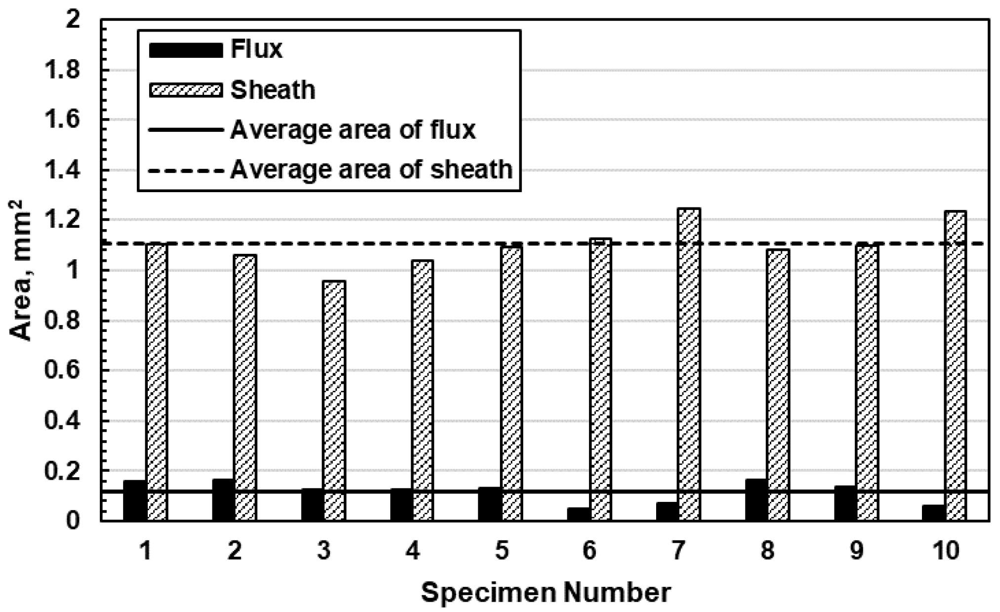
Figure 1. Sheath area and flux area in 10 cross-sections of flux-cored wire (S4Le).
Jmmp 08 00093 g001
Figure 2. Schematic illustration of the experimental set-up.
Jmmp 08 00093 g002
Figure 3. Laser energy density distribution at laser power 3.0 kW; (a) just focus; (b) defocus +15 mm; (c) defocus +20 mm; (d) defocus +40 mm.
Jmmp 08 00093 g003
Figure 4. Profile of the tensile test specimen (dimensions are in mm).
Jmmp 08 00093 g004
Figure 5. Appearance and high-speed images of molding body with varying laser spot size. (Condition Table 3(a)).
Jmmp 08 00093 g005
Figure 6. Appearance and high-speed image of a molding body molded at low process speed. (Condition Table 3(b)).
Jmmp 08 00093 g006
Figure 7. Cross-sectional SEM images at interface at low process speed. (Condition Table 3(b)).
Jmmp 08 00093 g007
Figure 8. Appearance and high-speed image of molding body by FCW with varying laser power. (Condition Table 3(c)).
Jmmp 08 00093 g008
Figure 9. Cross-sectional SEM images at interface. (Condition Table 3(c)); (a) laser power 4.7 kW; (b) laser power 6.0 kW.
Jmmp 08 00093 g009aJmmp 08 00093 g009b
Figure 10. Relationship between laser power and IMC thickness.
Jmmp 08 00093 g010
Figure 11. Cross-sections and SEM images at interface; (a) flux-coated type (Condition Table 4(a)); (Condition Table 3(c)); (b) FCW type (Condition Table 4(b)).
Jmmp 08 00093 g011
Figure 12. Line analysis results of elements at the interface by EDX; (a) flux-coated type (Condition Table 4(a)); (b) FCW type (Condition Table 4(b)).
Jmmp 08 00093 g012
Figure 13. SEM images of fracture surface; (a) macro image of specimen No. 1, flux coated (b) macro image of specimen No. 3, flux coated; (c) macro image of specimen No. 2, FCW; (d) macro image of specimen No. 5, FCW; (e) micro image of specimen No. 1, flux coated; (f) micro image of specimen No. 3, flux coated; (g) micro image of specimen No. 2, FCW; (h) micro image of specimen No. 5, FCW.
Jmmp 08 00093 g013
Figure 14. EDX point analysis results at particle on fracture surface of the low-tensile-strength specimen. (Flux-coated specimen No. 3).
Jmmp 08 00093 g014
Table 1. Chemical composition of base metal.
Material, Mass %CSiMnPSNiCrFe
SUS3040.050.530.890.0310.0028.0818.2Bal.
Table 2. Chemical composition of filler wire.
Material, Mass %SiFeCuMnMgCrZnTiAl
A5183-WY<0.40<0.40<0.100.5~1.00.05~0.250.170.25<0.15Bal.
Table 3. Experimental conditions. (Derivation of appropriate process conditions).
(a)(b)(c)
Laser power, kW3.5~4.52.34.7~6.0
Spot shape, mm2.5 × 5.02.5 × 5.02.5 × 5.0
Defocus length, mm+15, +20, +40+15+25
Process speed, m/min411.5
Wire feeding, m/min1288
Hot-wire current, A165~168184188
WireA5183-WYA5183-WYFCW
Table 4. Experimental conditions. (Strength evaluation specimen).
(a)(b)
Layer12~912~9
Laser power, kW2.32.2~2.54.32.2~2.4
Spot shape, mm2.5 × 5.02.5 × 5.02.5 × 5.02.5 × 5.0
Defocus length, mm+100+250
Process speed, m/min0.720.50.720.5
Wire feeding, m/min8585
Hot-wire current, A1639919099
WireA5183-WYA5183-WYFCWA5183-WY
Table 5. Tensile test results. (Condition Table 4(a)).
Specimen No.Tensile Strength, MPaFracture Location
No. 195.9Boundary
No. 2131.5Boundary
No. 3151.2Boundary
No. 4124.0Boundary
No. 5133.3Boundary
Ave. of 5 specimens.127.2
Std. of 5 specimens.20.1
Table 6. Tensile test results. Condition Table 4(b)).
Specimen No.Tensile Strength, MPaFracture Location
No. 1124.5Boundary
No. 295.9Boundary
No. 3111.1Boundary
No. 4152.4Boundary
No. 5163.9Boundary
Ave. of 5 specimens.129.6
Std. of 5 specimens.28.3
Disclaimer/Publisher’s Note: The statements, opinions and data contained in all publications are solely those of the individual author(s) and contributor(s) and not of MDPI and/or the editor(s). MDPI and/or the editor(s) disclaim responsibility for any injury to people or property resulting from any ideas, methods, instructions or products referred to in the content.