Article

Experimental Characterization of Screw-Extruded Carbon Fibre-Reinforced Polyamide: Design for Aeronautical Mould Preforms with Multiphysics Computational Guidance

by
Juan Carlos Antolin-Urbaneja
1,*,
Haritz Vallejo Artola
1,
Eduard Bellvert Rios
1,
Jorge Gayoso Lopez
1,
Jose Ignacio Hernández Vicente
1 and
Ana Isabel Luengo Pizarro
2
1
TECNALIA, Basque Research and Technology Alliance (BRTA), 20009 Donostia-San Sebastian, Spain
2
Internacional de Composites S.A., 45007 Toledo, Spain
*
Author to whom correspondence should be addressed.
J. Manuf. Mater. Process. 2024, 8(1), 34; https://doi.org/10.3390/jmmp8010034
Submission received: 14 December 2023 / Revised: 5 February 2024 / Accepted: 6 February 2024 / Published: 9 February 2024
(This article belongs to the Topic Advanced Composites Manufacturing and Plastics Processing)

Abstract

:
In this research work, the suitability of short carbon fibre-reinforced polyamide 6 in pellet form for printing an aeronautical mould preform with specific thermomechanical requirements is investigated. This research study is based on an extensive experimental characterization campaign, in which the principal mechanical properties of the printed material are determined. Furthermore, the temperature dependency of the material properties is characterized by testing samples at different temperatures for bead printing and stacking directions. Additionally, the thermal properties of the material are characterized, including the coefficient of thermal expansion. Moreover, the influence of printing machine parameters is evaluated by comparing the obtained tensile moduli and strengths of several manufactured samples at room temperature. The results show that the moduli and strengths can vary from 78% to 112% and from 55% to 87%, respectively. Based on a real case study of its aeronautical use and on the experimental data from the characterization stage, a new mould design is iteratively developed with multiphysics computational guidance, considering 3D printing features and limitations. Specific design drivers are identified from the observed material’s thermomechanical performance. The designed mould, whose mass is reduced around 90% in comparison to that of the original invar design, is numerically proven to fulfil thermal and mechanical requirements with a high performance.

1. Introduction

Traditionally, moulds for manufacturing fibre-reinforced polymer matrix composite components for the aeronautical sector include low-cost metals such as aluminium or plain carbon steel; high-end nickel–steel alloys such as invar; and composites [1,2,3]. Invar is usually the preferred material due to its unique dimensional stability and proper material properties, which facilitate the fulfilment of the strict tolerances required by end users. Aluminium is also frequently used because it is lighter and easier to machine than invar. Mechanical and thermal requirements are commonly specified, which aim at ensuring the parts’ dimensional tolerances and the needed material properties, respectively. The thermomechanical properties of metallic materials are commonly well known, so moulds can be designed based on accurate simulations that allow designers to numerically validate their behaviour under operating conditions. However, the prices and lead times of large metallic moulds are high. Therefore, alternative materials, structures and manufacturing technologies are being investigated to provide lightweight, low-cost, durable and functional tools for manufacturing high-performance composite structures [2,4].
Moulds made by tooling prepreg laminates from a machined master model are also being developed. In this regard, Galiana et al. [5] conducted a cost analysis of the engineering, management and production of an autoclave curing mould when using a carbon fibre-reinforced polymer (CFRP) or invar, providing guidelines for their selection. CFRP properties have been extensively analysed; therefore, composite mould designs with multiphysics computation guidance are regularly used [6,7]. In fact, CFRPs usually have a low coefficient of thermal expansion (CTE), thus minimizing problems related to shrinkage and spring-back. Nevertheless, metal moulds used and maintained properly can have a long service life for the mass production of thousands of composite parts. On the other hand, tooling prepreg moulds are limited to service in relatively low-volume production areas [3], mainly due to the surface wear at the lamination area and to the development of interlaminar vacuum leaks, which are difficult to repair. In addition, the manufacturing of moulds with tooling prepreg is tedious due to the bonding of the master boards together, their subsequent machining and the application of coatings, and the need to reinforce the laminated skin with a reinforced backing structure [8].
Regarding new manufacturing technologies, additive manufacturing (AM) described in the UNE-EN ISO/ASTM 52900:2021 standard [9] has become a very interesting alternative technology to commonly used machinery for the development of moulds because of associated reductions in lead time, material waste and manufacturing costs [10,11,12,13]. Moreover, some investigations have focused on additive manufacturing’s impact in the supply chain due to the fact that customers can turn into manufacturers by printing their products on demand and reducing their stock [14]. One of these additive manufacturing technologies is focused on material extrusion, in filament or pellet form. In the past few years, there has been an increasing amount of interest in assessing this technology, i.e., developing parts for different applications [15,16]. However, the development of large moulds made of thermoplastics to be used for the production of aeronautical composite parts using additive manufacturing technology is not easy, since there are very few technical materials that can withstand the curing conditions [17]. Based on research conducted by Olusanmi Adeniran et al. [6], in which a review of the different thermoplastic matrices for additive manufacturing is carried out, these can be classified by commodity, engineering and high-performance grades. As a general rule, aeronautical requirements imply the use of high-performance grade materials, which can generally be found commercially in filament form for FDM (fused deposition modelling) technology [18] at high prices with critical processing parameters [19,20]. Another more economical alternative is to use engineering-grade thermoplastics with short-fibre reinforcements [17,21,22]. In this regard, Ahmed Arabi Hassen et al. [23] describe the development of autoclave moulds that can be used to fabricate aerospace composite parts with materials that are capable of withstanding elevated temperatures, such as polyphenylene sulphide (PPS) with variations in high carbon fibre loading (40%, 50% and 60% by weight). In the same line, Park et al. developed and tested plastic injection moulds using polyetheretherketone (PEEK) after manufacturing samples at different high temperatures [24].
Most research studies about the additive manufacturing of thermoplastic polymers are focused on the analysis of FDM producibility parameters [25,26,27]. However, additive manufacturing technology presents some limitations for the fabrication of large moulds [28]. Consequently, in recent years, there has been growing interest in the aeronautical industry in concepts such as big area additive manufacturing (BAAM) [29,30,31], wide and high additive manufacturing (WHAM) [32] and large-format additive manufacturing (LFAM) [33] for producing large moulds using extrusion-based additive manufacturing (EAM) technology with thermoplastic materials in pellet form. Some of these forms of thermoplastic materials reinforced with chopped fibre increase the deposition rate using direct extrusion, being much more economical in terms of energy intensity consumption [30]. Pignatelli [15] reviewed the responses of large-format pellet-based AM systems introduced in the last decade to different real-world market applications. Among these different uses, the production of tooling for the automotive sector [34,35], moulds for the naval sector [36,37] and moulds for the manufacture of wind turbine blades for the wind energy sector [30,38,39] were highlighted.
Generally, suppliers of the materials to be printed using extrusion AM technology provide a basic characterization of the printed samples under specific parameters related to the temperature or printing speed, among others [40]. Most studies regarding engineering-grade polyamide 6 reinforced with carbon fibre (PA6/CF) are focused on the analysis of FDM producibility parameters. In this sense, the material properties of PA6/CF highly depend on the material form, CF content, manufacturing process and corresponding parameters [26,41,42,43,44] being available at room temperature upon request. For example, Table 1 shows the relevant mechanical properties at room temperature of two different polyamides reinforced with 20% carbon fibre after different processing methods. It is remarkable that the mechanical properties of the BergamidTM B70 KF20 Black do not depend on the material orientation in this case, as they have been obtained from an injection process. In addition, the values published for the tensile modulus and strength are significantly higher than the ones obtained via FDM. The density of the material is also higher.
In case of PA6/CF pellet extrusion-based AM, the data available are very limited and experimental works are being carried out currently to better understand their properties. For example, Xiping Li et al. [43] carried out a detailed material characterization regarding their mechanical properties by assessing the tensile and flexural moduli and strengths depending on the carbon fibre content. They determined that the highest tensile properties at room temperature are obtained for a fibre content of 25%. In this case, a maximum Young’s modulus of 6.9 GPa and a maximum tensile strength of 169.7 MPa were obtained. Moreover, they analysed how the operating temperature affects the tensile properties, determining that, in the case of a polyamide reinforced with 35% carbon fibre, the modulus and strength at 150 °C are 75% and 70% lower, respectively, than those at room temperature. Furthermore, Nevine Tagscherer et al. [47] characterized 40% chopped carbon fibre-reinforced polyamide 6 at room temperature with production parameter variations, obtaining a maximum longitudinal modulus of 12.8 GPa. In addition, it was determined that the transversal tensile strength is up to 27% that of the longitudinal, and the transverse tensile modulus is up to 20% that of the longitudinal.
Despite the number of works published in regards to PA6/CF, there is very little information about the dependency of the material properties on the temperature and process parameters, such as printing paths, the nozzle diameter and bead dimensions, which are all considered to be cornerstones. Moreover, the thermal diffusion and thermal expansion of the material are not well known either. Further, the porosity of printed PA/CF has rarely been studied, though the ASTM standard defines two types of porosities generated during AM processes. In addition, pores have an effect on the mechanical properties of manufactured parts in AM [48]. These key deficiencies in our knowledge about this material prevent designers, engineers and manufacturers from accurately analysing how the material behaves under operating conditions (i.e., due to the temperature and pressure inside an autoclave during curing processes) and consequently prevents the development of proper aeronautical mould designs for the manufacturing of composite parts. On the whole, further research is required to improve the knowledge on the actual thermomechanical performance of aeronautical moulds printed through pellet-based PA6/CF.
In the present paper, an extensive mechanical characterization of pellet-based PA6 reinforced with 20% short carbon fibre that is randomly distributed in the polymer is completed for the development of 3D-printed aeronautic mould preforms for composite manufacturing. Furthermore, a comparison between printed tensile test probes’ performance manufactured by three different additive manufacturing machines with different parameters is included. Also, the porosity via optical microscopy and the density of printed specimens have been evaluated as these can critically affect the mechanical strength and stiffness, among other parameters [48]. Based on the experimental data obtained, a detailed design process is carried out with finite element analysis (FEA) guidance to accurately predict the thermoelastic behaviour of an aeronautical mould under realistic operating conditions. According to end-user needs, particular thermal and mechanical requirements are specified to guarantee the manufacturing of composite parts with adequate dimensions and material properties. Through these computer modelling activities, several potential problems related to the material behaviour of moulds printed through this technology are identified, and design drivers to overcome them are applied; thus, they are capable of fulfilling the requirements of end users. Apart from this introduction, the paper is divided into four main sections. Section 2 includes a description of a use case in which an aeronautical mould and its requirements are presented. Section 3 describes our methodology, including the working procedure, the material characterization and the computer modelling stages. Section 4 shows the results of the experimental characterization campaign, along with the numerical results for validating the thermoelastic performance of the designed mould. Also, potential problems when using this material for the development of aeronautical moulds are outlined. Finally, in Section 5, the conclusions and prospects for future work are summarized.

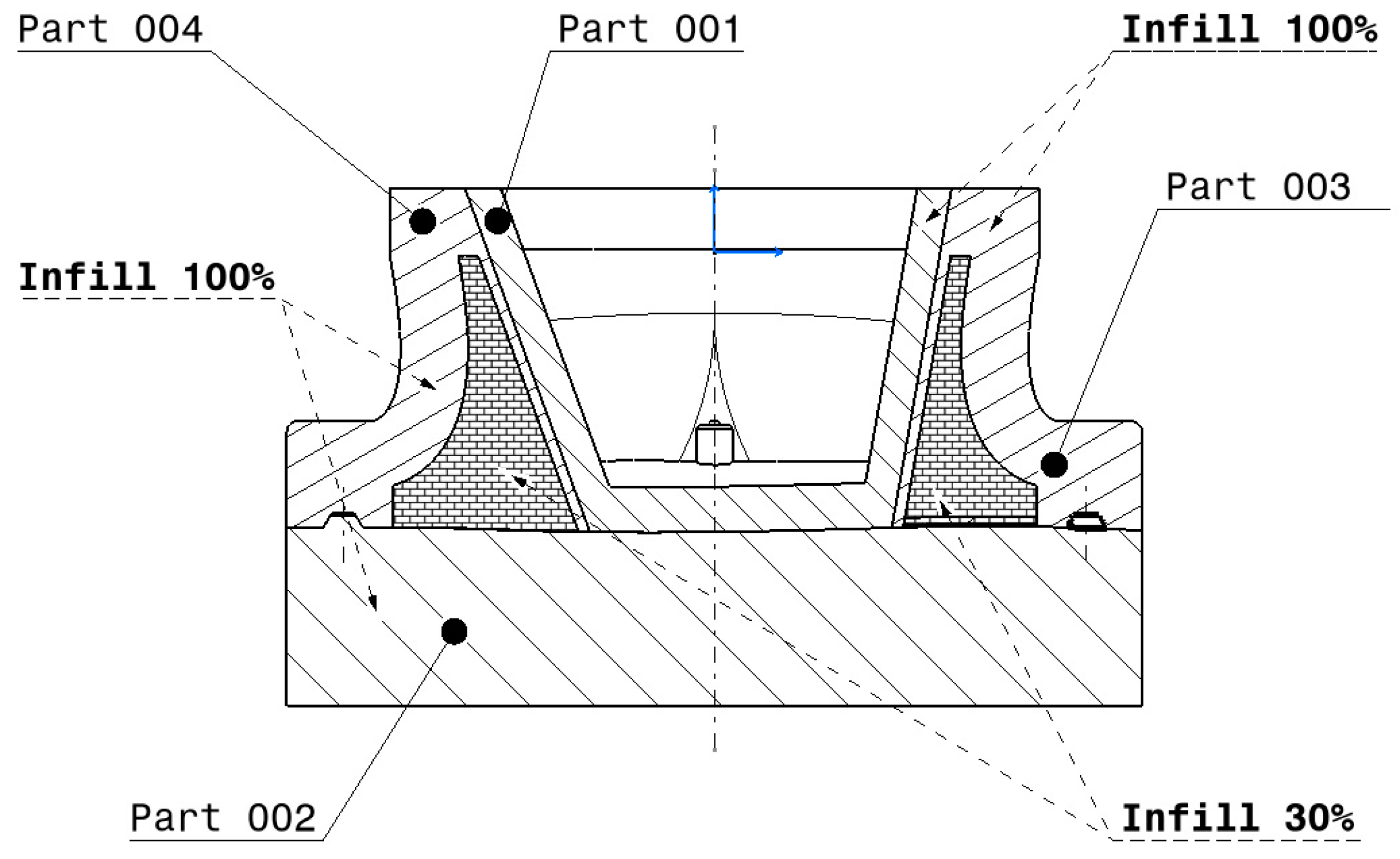
2. Description of the Use Case

Our current research is focused on an application in aeronautics, as specified by the end user, in which a mould, also called tool, is required for manufacturing inside an autoclave an aeronautical composite prepreg part, which is marked by the engineering edge of part (EEOP) and the manufacturing edge of part (MEOP) area as seen in Figure 1. The EEOP indicates the dimensions of the finished part, while the MEOP denotes the boundary to be used for manufacturing the laminate. Currently, the end user relies on an invar mould. Because of the complex geometry of the composite part, the mould must be formed by several semi-moulds to ensure the part can be suitably extracted after the curing process. The overall dimensions of the tool are approximately 400 mm × 300 mm × 250 mm.
Regarding the working conditions corresponding to this mould, the end user indicates that the manufacturing process is conducted in an autoclave. In this regard, a particular thermal cycle, characterized by a dwell time of 1 to 5 h at 80 °C and a curing phase of 2 to 6 h at 180 °C, is specified. Heating rates are required to be in the 1.5 to 3 °C/min range. Besides the pressure exerted by the compaction of the vacuum bag, the mould is stated to be subject to an additional pressure of 7 bar which is applied by the autoclave.
Concerning the final properties required for the mould, mechanical and thermal requirements are specified by the end user. On the one hand, it is required that the maximum deflection at the lamination surface must be lower than 0.1 mm during the curing stage. On the other, it is required that the temperature at the lamination surface must be able to properly follow the thermal cycle specified above, with the maximum delay between the maximum and minimum temperatures along the lamination surface below 2 h.

3. Methodology

The main steps of our methodology for the current research study to design the aeronautical mould are shown in Figure 2. Firstly, the material that best fits the end-user requirements is assessed based on properties found in the literature.
The chosen thermoplastic material must be printable without using a heating chamber. Providing high-performance-grade polymers require highly controlled conditions to be printed [49], a preselection of engineering thermoplastic materials (allowing broaden range for printing conditions) was conducted [6]. As the tool has to support up to 180 °C at 7 bar during the autoclave process, a preselection of engineering thermoplastic materials was carried out, taking into account the available data provided by the potential suppliers. The preselected material for manufacturing the moulds was polyamide 6 reinforced with short carbon fibre (20%) that was randomly distributed in the polymer, which is included in Table 1 and was supplied by Avient [46]. This thermoplastic material is classified as semi-crystalline [6,19]; therefore, the service temperature is between the glass transition temperature, Tg (60 °C), and the melting temperature, Tm (222 °C), according to the results of the differential scanning calorimetry (DSC) technique carried out using the printed material and the Q100 model (TA Instruments, New Castle, UK). Also, one of the properties able to indicate the stiffness for thermoplastics in service is the heat deflection temperature (HDT). The HDT values provided of the filament form in the datasheets of [45] are within the range of the thermal specifications. However, the performance of the thermoplastic polymer at specific required conditions (in filament or pellet form) is not available in the datasheet. Therefore, an extensive experimental characterization campaign, including tensile, compression, flexural and shear tests, has been completed to enable a detailed assessment of the performance of PA6/CF 20% under operating conditions. The material’s thermal conductivity, specific heat at room temperature and CTE in the 25 °C to 180 °C range are also characterized. This extensive experimental characterization campaign was performed using specimens obtained after being printed by a research additive manufacturing system (RAMS). Taking into account that the mould preforms will be printed using another additive manufacturing systems (AMS), some similar specimens were characterized to compare the quality between the printed beads in different AM machines.

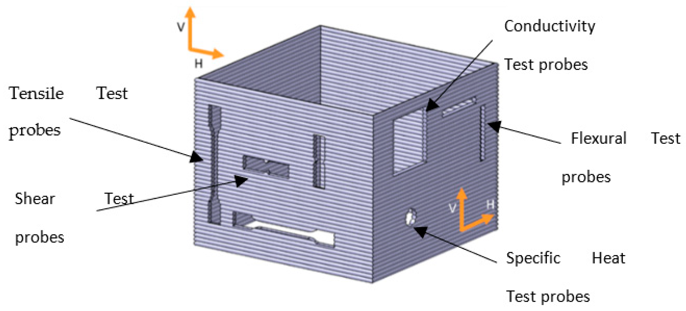
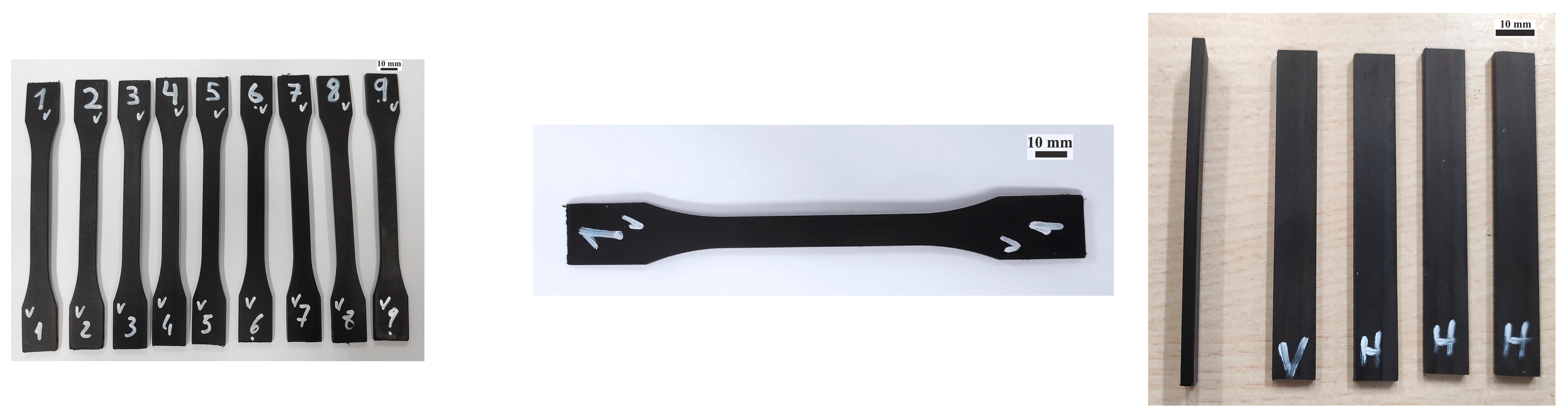
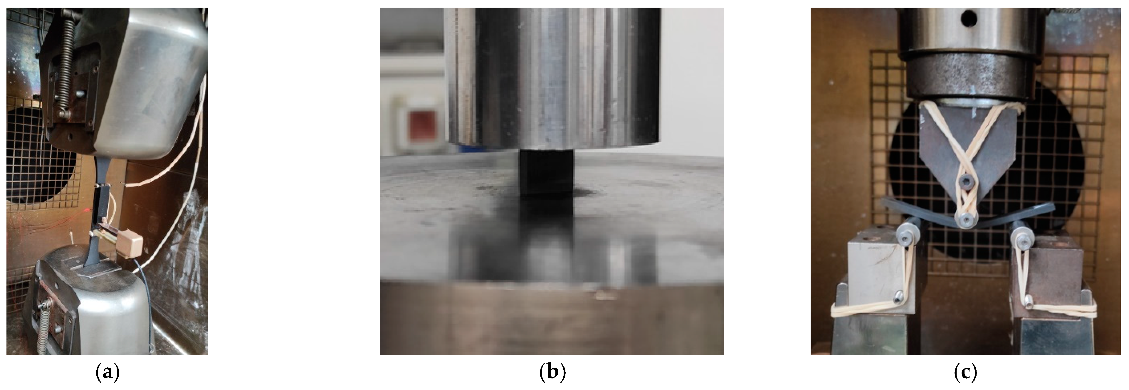
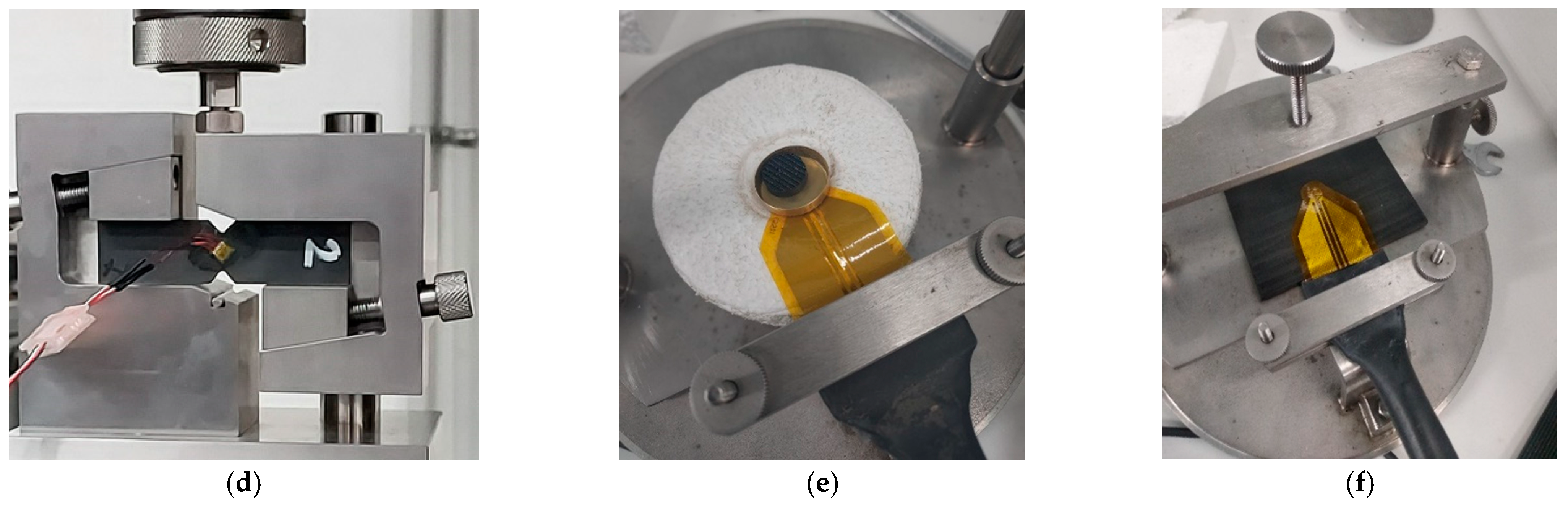
3.1. Material Characterization

In order to characterize the printed material, a part was first designed to contain all the envisaged test probes. As an illustration of the types of specimens included, Figure 3 shows the design of a cube in which the type of test probe is represented according to the standards indicated in Table 2. The original part was printed by depositing theoretical 5 mm thick and 1.5 mm high beads using a robotic system (RAMS) similar to the one illustrated in Figure 4 (right), in which a 20XD extruder is attached [50]. The different test specimens have been machined from a square printed cube of 300 × 300 × 290 mm3 (Figure 4 (left)).
Recently, a study evaluating the printability and mechanical properties of regrinding material previously used in large-format additive manufacturing was conducted. It included an assessment of similar printed parts for the machining of tensile and flexural samples in a similar way [51]. It is noteworthy that the process parameters were iteratively optimized by means of several tests in order to ensure proper manufacturing. Being an orthotropic material, the testing samples are horizontally (H) or vertically (V) machined to obtain the corresponding properties in the printing (1) and stacking (2) directions, respectively. It is assumed that properties in the printing and stacking directions are constant for each wall.
Samples for the tensile and shear tests in horizontal and vertical orientations were machined from wall A and B, respectively. Samples for the flexural test in both directions were obtained from wall C. The machined specimens for the tensile and flexural tests are shown in Figure 5. Finally, samples for the compression, conductivity and specific heat tests were machined from wall D. As one of the requirements is related to rugosity, three additional samples were machined under the same conditions to evaluate the rugosity under the ISO 4287:1997 standard [52] using a Surftest SJ-210 (Mitutoyo, Kawasaki, Japan). The mean values were 3.013 ± 0.568 µm, showing good machinability. As presented in Table 2, the mechanical tests were repeated at three temperatures (i.e., room temperature (RT), 80 °C and 180 °C) to investigate the temperature dependency of the properties. A total of 98 samples were tested during this characterization stage. Figure 6 shows some of the specimens under the tests. Also, some additional samples were machined to assess the difference between specimens printed by three similar machines to compare the behaviour of the same material while applying other process parameters. For the mechanical characterization of the specimens, a Model Instron 5500 R6025 (Instron, Norwood, MA, UK) universal testing machine applying a 100 kN load cell was used. The thermal conductivity and specific heat were determined utilizing a hot disk unit in combination with the measurement unit transient plane surface (TPS) 2500S (Hot Disk AB, Göteborg, Sweden). The CTE was experimentally calculated using the dynamic mechanical thermal analysis (DMTA) technique by means of a Tritec 2000 DMA device (Triton Technology Ltd., Nottinghamshire, UK).
Table 2. Tests conducted with the samples manufactured with RAMS, corresponding standards, obtained properties and testing conditions.
TestStandardObtained PropertiesMaterial OrientationTemperature
[°C]
Number of Samples
TensileISO 527-1 [53]
ISO 527-2
1B Specimens [54]
Tensile Strength
Tensile Modulus
Nominal Strain at Break
1RT3
803
1803
2RT3
803
1803
FlexuralISO 14125
3-point test [55]
Flexural Strength
Flexural Modulus
Flexural Strain at Max Load
1RT3
803
1803
2RT3
803
1803
Compression–StrengthISO 604
Standard Specimens [56]
Compression Strength
Compression Strength (5%)
1RT3
803
1803
2RT3
803
1803
Compression–ModulusISO 604
Standard Specimens [56]
Compression Modulus1RT3
803
1803
2RT3
803
1803
ShearASTM D5379 (Iosipescu Fixture) [57]Ultimate Strength
Shear Cord Modulus
1RT3
803
1803
2RT3
803
1803
DMTAISO 6721 [58]CTE2−25 ÷ 1801
Hot discISO 22007-2.2 [59]Thermal conductivity
Specific heat
1RT1
2RT2
RugosityISO 4287:1997 [52]Rugosity, Ra-RT3
DensityUNE-EN ISO 1183-1:2019 [60]Density-RT1
Additionally, the tensile properties at room temperature (RT) are compared with those published in the Technical Data Sheet of BergamidTM B70 KF20 Black processed by injection moulding by Avient [46]. Moreover, additional tensile samples are manufactured using two different 3D printing machines (AMS I—Additive Manufacturing System I and AMS II—Additive Manufacturing System II) to investigate if similar material properties are obtained. Furthermore, in case of AMS II, samples are printed by using two bead heights, AMS II (1) and AMS II (2), to compare how this printing parameter affects the tensile strength and modulus. The main characteristics and parameters used with the different AM machines are shown in Table 3. As the average dispersion of the measurements (the standard deviation divided by the mean value) was about 5% and the budget was limited, the quantity of samples in each test was restricted to three samples.
In order to determine the quality of the bead deposition compared to theoretical ones, an evaluation of the bead height and width was performed using image analysis techniques. Hence, some micro- and macro-photographs of the bead structure and profile were obtained for each case in our study to evaluate the porosity and the maximum length of the short carbon fibres in the printed beads. Moreover, some additional specimens were machined to calculate the density of the printed material in each case in our study, geometrically and experimentally, by means of the Archimedes method.

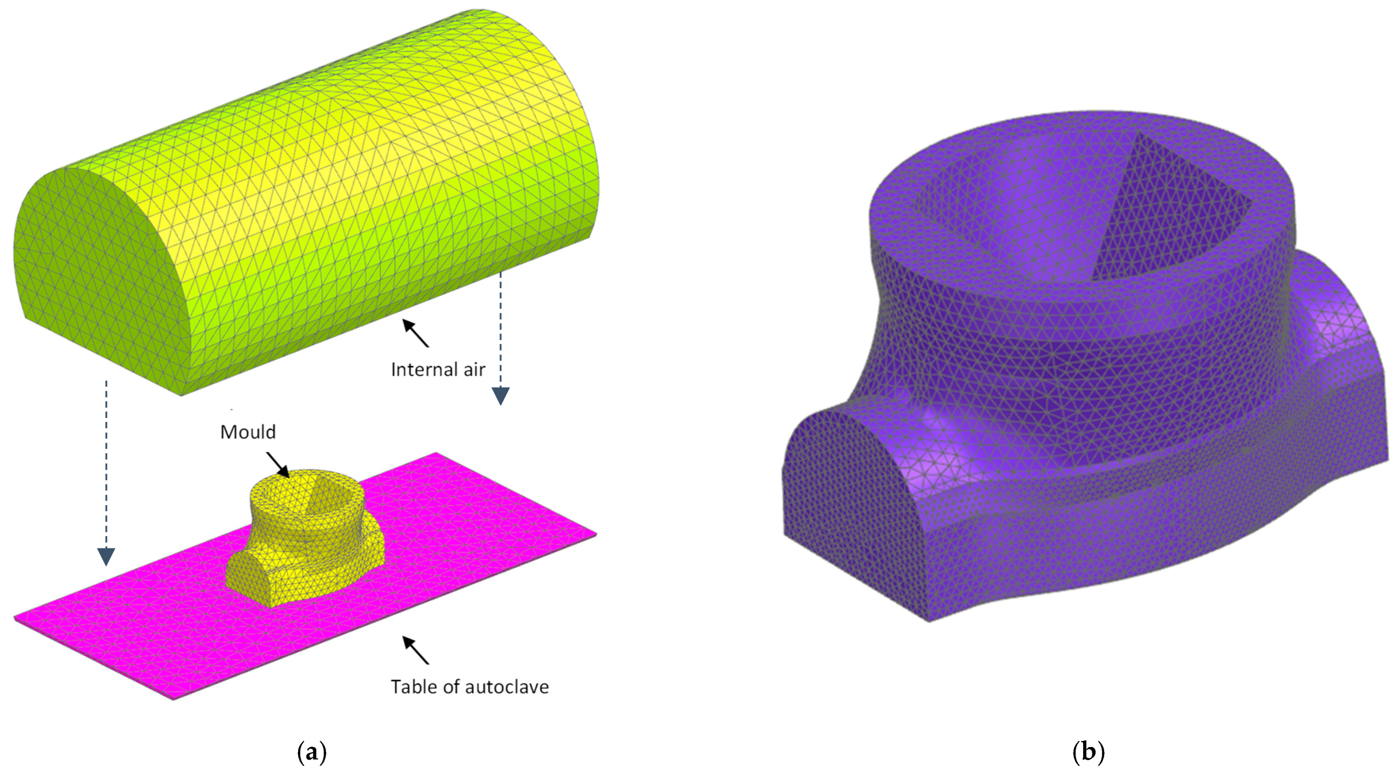
3.2. Preliminary Computer Modelling of the Mould

In a parallel effort, an initial design is proposed for each semi-mould out of the entire mould, keeping in mind how to assemble and dissemble them to ensure successful composite part extraction once they are manufactured. Specific fabrication features and limitations are also taken into account in this initial step. Subsequently, the mould design is iteratively developed, based on computer-aided engineering (CAE), and taking into account the material properties obtained in the characterization stage, until a lightweight mould that fulfils the specified requirements is obtained. The production strategy is also optimized, and a better mould position is proposed to improve its thermal response. Computer modelling activities are carried out with Simcenter 3D 2021.2. (1998). Regarding the developed models, solid meshes are used for both the thermal and mechanical simulations as seen in Figure 7. Specific load cases that digitally reproduce the loads and the boundary conditions under the mould are included in the numerical models. For the thermal simulations, a semi-circular autoclave (Ø700 × 1400 mm) is modelled. The analytical estimation of representative convection coefficients along geometrically complex moulds inside an autoclave is not easy, so the results of single thermal analyses with imposed heat transfer coefficients might not be accurate enough for this application. Therefore, coupled thermal-flow analyses, in which the convection coefficients are calculated based on representative operating conditions, are performed instead. To that end, the air volume in contact with the mould is included in the model, and specific air inlets and openings are applied. In particular, an air velocity of 1.75 m/s is considered. The mathematical model developed for this activity is formed by around 42,000 linear tetrahedral elements and 11,000 nodes. A general thermal impedance of 2000 W/m2 K is modelled among the solid components. For the mechanical analyses, a finite element model formed by around 76,000 parabolic tetrahedral elements and 115,000 nodes is built. Rigid joints are considered among the semi-moulds. The transient temperature contours from the thermal analysis are defined as thermal loads, assuming a stress-free temperature of 20 °C. The operating pressure and gravity are also applied. A rigid joining is considered among the semi-moulds.

4. Results and Discussion

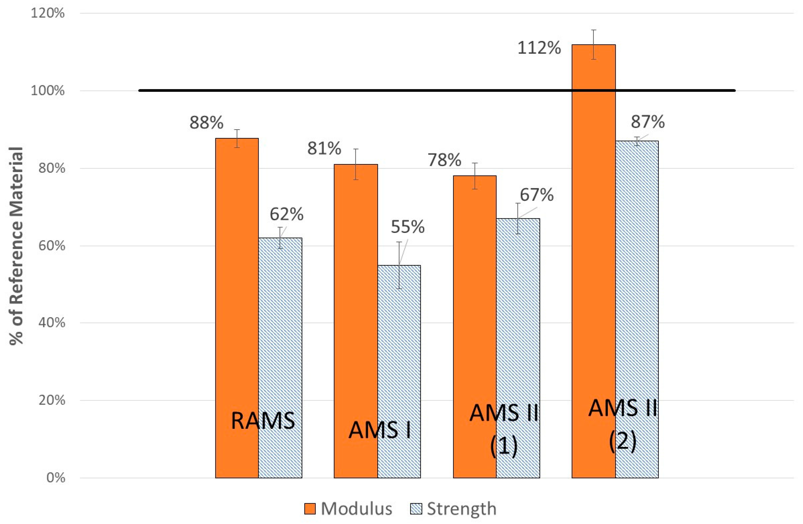
4.1. Tensile Moduli and Strength Results

The printed material is highly machinable; therefore, testing samples can be easily obtained. Moreover, a good level of machinability is obtained for each machining process performed, regardless of the printer or the process parameters used in the manufacturing of the part from which the sample is extracted. In this regard, the surface roughness, Ra, was measured under the UNE-EN ISO 4287 [52] and UNE-EN ISO 4288 standard [61] as 2.388 to 3.496 µm, according to the tests conducted.
Concerning the experimental results obtained from the extensive characterization stage conducted for the samples manufactured with RAMS, it is noteworthy that the ratio between the longitudinal and transversal moduli and strengths at room temperature is in line with the values published by Nevine Tagscherer et al. [47]. For convenience, only the results of the tensile moduli and strength at three temperatures, RT, 80 °C and 180 °C, are provided. As derived from Figure 8, the tensile strength and modulus decrease dramatically. In this sense, the tensile strength in the printing bead direction is reduced by about 37% and 70% at 80 °C and 180 °C, respectively; meanwhile, the tensile modulus is reduced up to 56% and 71%. In the stacking direction, the tensile strength is reduced by 10% (80 °C) and 73% (180 °C). The tensile modulus is reduced by up to 73% (80 °C) and 85% (180 °C). The reduction in these mechanical properties at a high temperature is very typical in polymers, as explained in [62]. The results in the bead direction depend on the material matrix—in this case, reinforced with 20% carbon fibres. However, the results in the stacking direction depend on the layer union interface and the effect of the adhesion of the different layers. The rest of the properties generated in our research are available upon request. They are included in registered software as part of TECNALIA’s intellectual property.
Taking into account that the mould preforms will be printed using AMS machines, some similar specimens are characterized to compare the quality between printed beads. As a consequence, the tensile properties at room temperature are assumed to be a good characteristic to use in such a comparison. The experimental results show a relatively low level of dispersion depending on the machine and the parameters used for the manufacturing of the sample, as depicted in Figure 9. In this sense, taking as a reference the properties of injected BergamidTM B70 KF20 Black processed by injection moulding, the material tensile modulus along the bead printing direction can decrease up to 78% or increase up to 112%. The lowest and highest obtained values for the material tensile strength are 55% and 87%, respectively. It is noteworthy that the most extreme values concerning the modulus are obtained for the same additive manufacturing machine. Accordingly, it is observed that the lower the bead height, the higher the tensile modulus. It is plausible that this effect is due to the layers being more compacted, consequently reducing the porosity, as estimated in Section 4.3. This parameter has a similar effect on the tensile strength of the material, but its influence is not so notable.

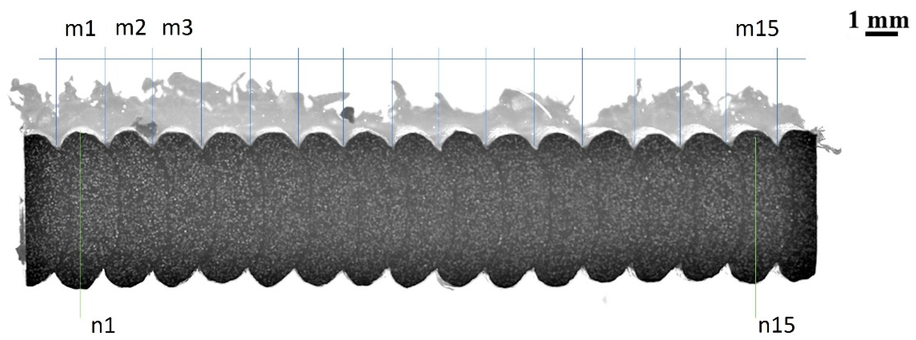
4.2. Bead Height and Width Assessment

At the beginning of our research, it was found that we needed to compare the bead height and width between the theoretical and the real deposited ones after the extrusion process. In this sense, some specimens of each cube were cut and prepared to measure them by means of image analysis software (Photoshop V11.0). In each macrograph, some measurements were selected under the area of the interest, determining the bead height (m) and width (n). Figure 10 illustrates an example of the measurement identification. The mean, standard deviation and error percentage between the theoretical and measured values of the printed cubes from each machine are included. This analysis found that the deposited bead size was quite well adjusted in each machine, although some additional adjustments are needed in the so-called AMS I machine. The compared values are included in Table 4.

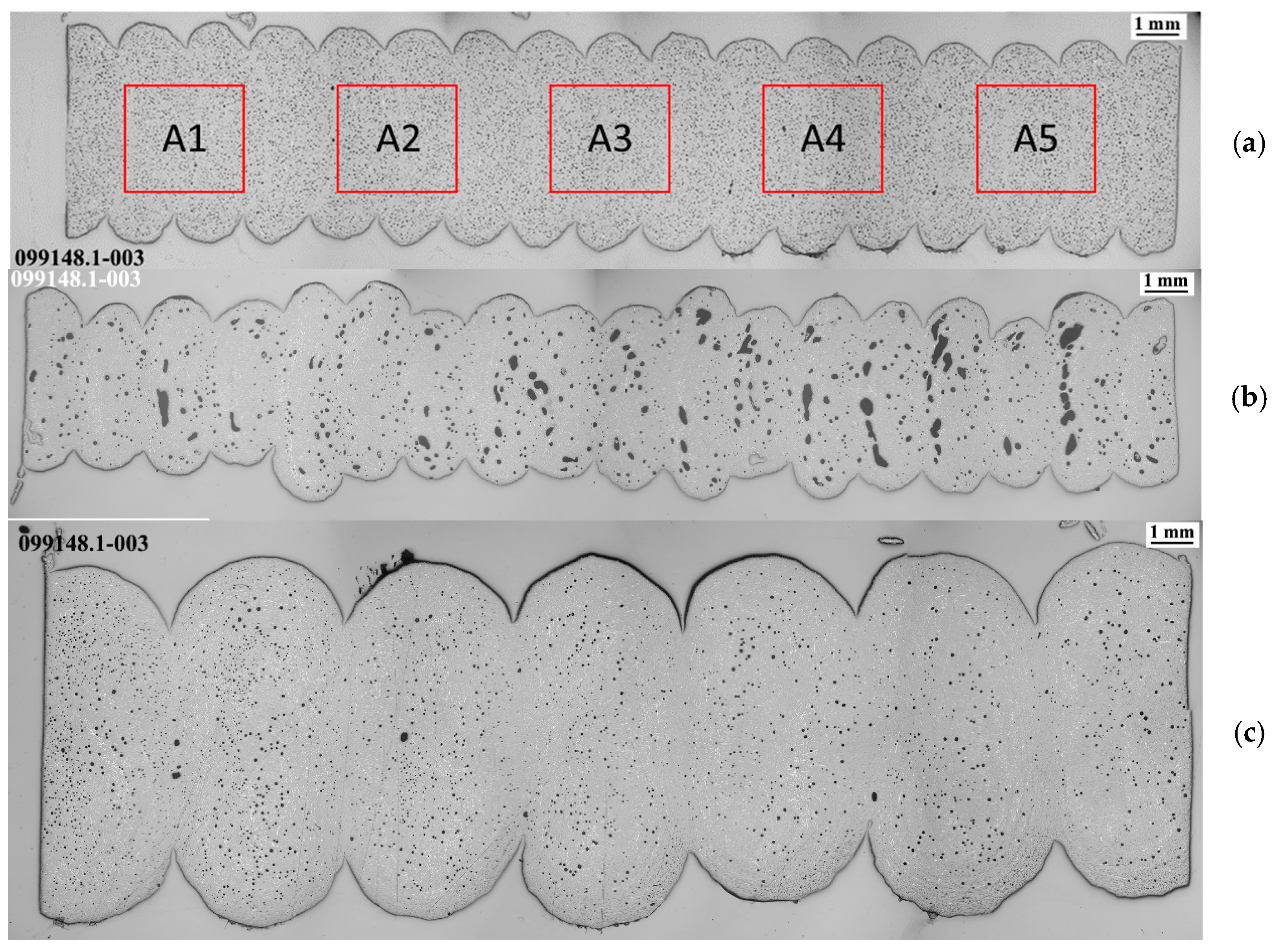
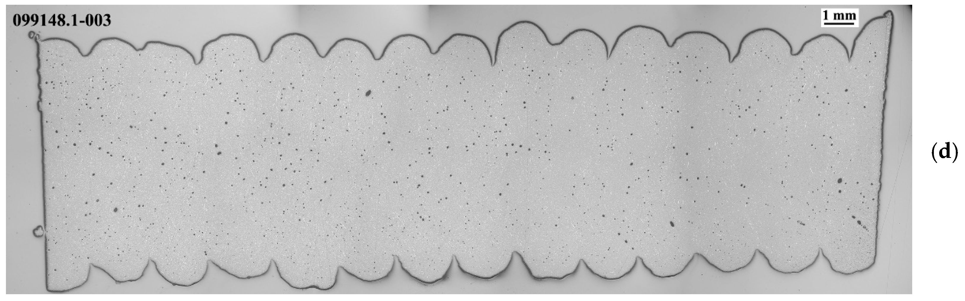
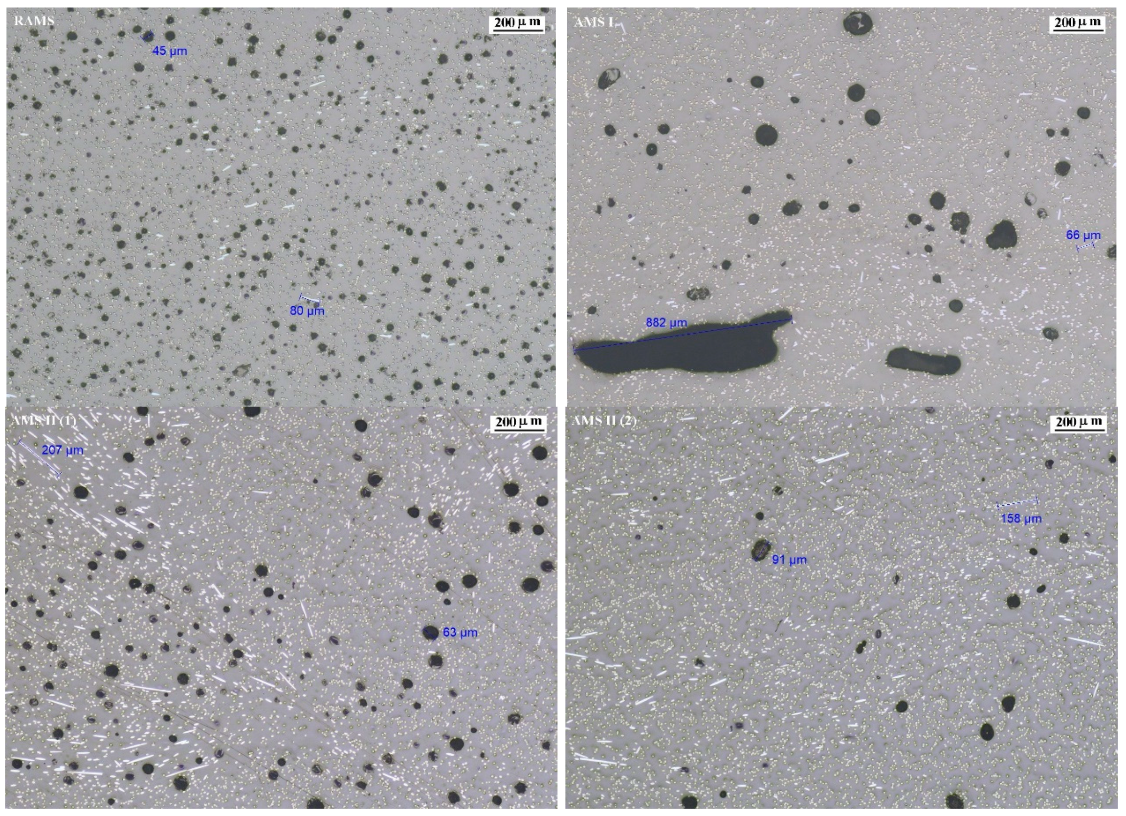
4.3. Porosity Evaluation

Another aim of this research is the evaluation of the porosity during the fabrication process before any post processing (i.e., thermal treatment) as the porosity can influence the mechanical characteristics of the tensile strength, as reviewed by Al-Maharma [48]. Moreover, the formation of voids is a common problem when fillers are introduced into a thermoplastic material [63]. In order to evaluate the porosity percentage of each case in our study, some specimens were cut and treated to be embedded in bakelite pieces. These parts were photographed and evaluated via inverted microscopy Eclipse MA200 (Nikon, Tokyo, Japan) in combination with properly calibrated analysis software.
To calculate the percentage of the porosity of the printed specimens, an analysis of the volumetric fraction of each case in our study was performed following an internal procedure based on the ASTM E562 standard [64]. Therefore, after the test specimen preparation, five representative and homogeneous areas of the total area illustrated in each macrograph of Figure 11 were selected, as shown in Figure 11a, which analyses the percentage in the area of interest.
For simplicity, only the first micrograph of each case in our study is included in Figure 12. In the images (with ×50 magnification), the polymer matrix (grey area) with short carbon fibres (white marks) and pores (black dots) can be seen. In this study, the longest short carbon fibres and the biggest pores were identified in each photograph. According to the magnified images, the pores are quite uniform (spherical) in each case, apart from AMS I, in which the pores are bigger and irregular. In fact, looking at the micrographs, there is a lower number of pores than in the other cases.
Separately, the porosity percentage was estimated in contrast with the polymer matrix and fibres. A summary of the results can be seen in Table 5, showing that the specimens printed using the AMSII machine with a lower bead height achieve the lowest porosity.

4.4. Density

An additional evaluation was performed in order to verify the density of the printed beads based on UNE-EN ISO 1183-1:2019 [60]. Therefore, a square plate approximately 30 mm × 30 mm and 3 mm thick was machined. The aim was to calculate the density experimentally through geometrical measurements and the Archimedes method using a Mettler AE 240 (Mettler-Toledo, Cornellá de Llobregat, Spain) weight balance and isopropanol-2 as a liquid medium. The results are included in Table 6, showing that all the calculated values are lower than those provided in the datasheet of the specimens processed by injection moulding (between 1.21 and 1.25 g/cm3).

4.5. Observed Potential Problems

During the computer modelling activities, some potential problems related to the thermoelastic performance of the carbon fibre-reinforced PA6 (manufactured via RAMS) were found. The authors believe that these issues, described in detail hereafter, may occur with any aeronautic mould made of this material and printed through this technology.
  • Severe CTE mismatch-related problems (critically high tensile states along the mould and/or highly heterogeneous deformations that cannot be compensated in practice) occur under operating conditions when using dissimilar materials (metallic screws/positioners to join the semi-moulds, for instance).
  • These problems might also occur in moulds that are entirely made of this material because its CTE is highly orthotropic.
  • Temperature-induced deformations along the fibre-perpendicular direction are large, much greater than the maximum deflection required, as a result of the material’s CTE.
  • Large displacements are caused in service along the fibre-perpendicular direction, greater than the maximum deflection required, due to the relatively low stiffness of the material at the operating temperature.
  • Because of the relatively low thermal diffusivity of the material, the thermal response of the mould is not valid (excessive thermal gradients on the lamination surface) if a light enough mould is not designed.
In our research, a specific design strategy is followed to overcome these issues by applying the design drivers described below. Our numerical results prove that this strategy allows us to meet the particular thermal and mechanical requirements specified by the end user for this work.
  • The use of dissimilar materials should be avoided.
  • It is recommended to follow strategic material deposition, thus printing each layer perpendicularly to the previous one (for example 0/90/0/90/etc.). Such a bidirectional printing strategy results in a mould with homogeneous orthotropic properties. Therefore, the deformations due to the thermal expansion become uniform along each direction, and direction-dependent scale factors can be applied to the original mould geometry to compensate for the large temperature-induced displacements.
  • In the case of moulds formed by several semi-moulds, it should be ensured that the printing and stacking directions of every semi-mould matches once the mould is assembled. Positioners made of the same material and placed so that the printing directions match with the ones of the mould should be used to join the semi-moulds.
  • From a mechanical point of view, solid moulds should be developed as a general rule. This way, in combination with the printing strategy described in 2, the deformations due to the operating pressure (which are stiffness dependent) become uniform, and direction-dependent scale factors to compensate for the pressure-induced displacements can be applied to the original mould geometry.
  • In terms of thermal performance, a thermally light design is required. Moreover, the design must enable similar thermal impedances at ambient temperature and the thermal capacitance should be as uniform as possible along the lamination surfaces to homogenise the temperature contour.
  • For the cases in which an entirely solid mould does not allow us to ensure proper thermal behaviour, infill volumes with a particular percentage of material should be designed instead of totally hollow parts. This way, a high enough stiffness can be kept without excessively enlarging the thermal capacitance of the component. The deformations due to the pressure might be uniform enough in these cases. Moreover, the scale factors for compensating for the deformations due to the autoclave process could be applied to result in a proper thermal response.
Table 7 identifies the potential problems related to the material performance under operating conditions with design drivers to overcome them.

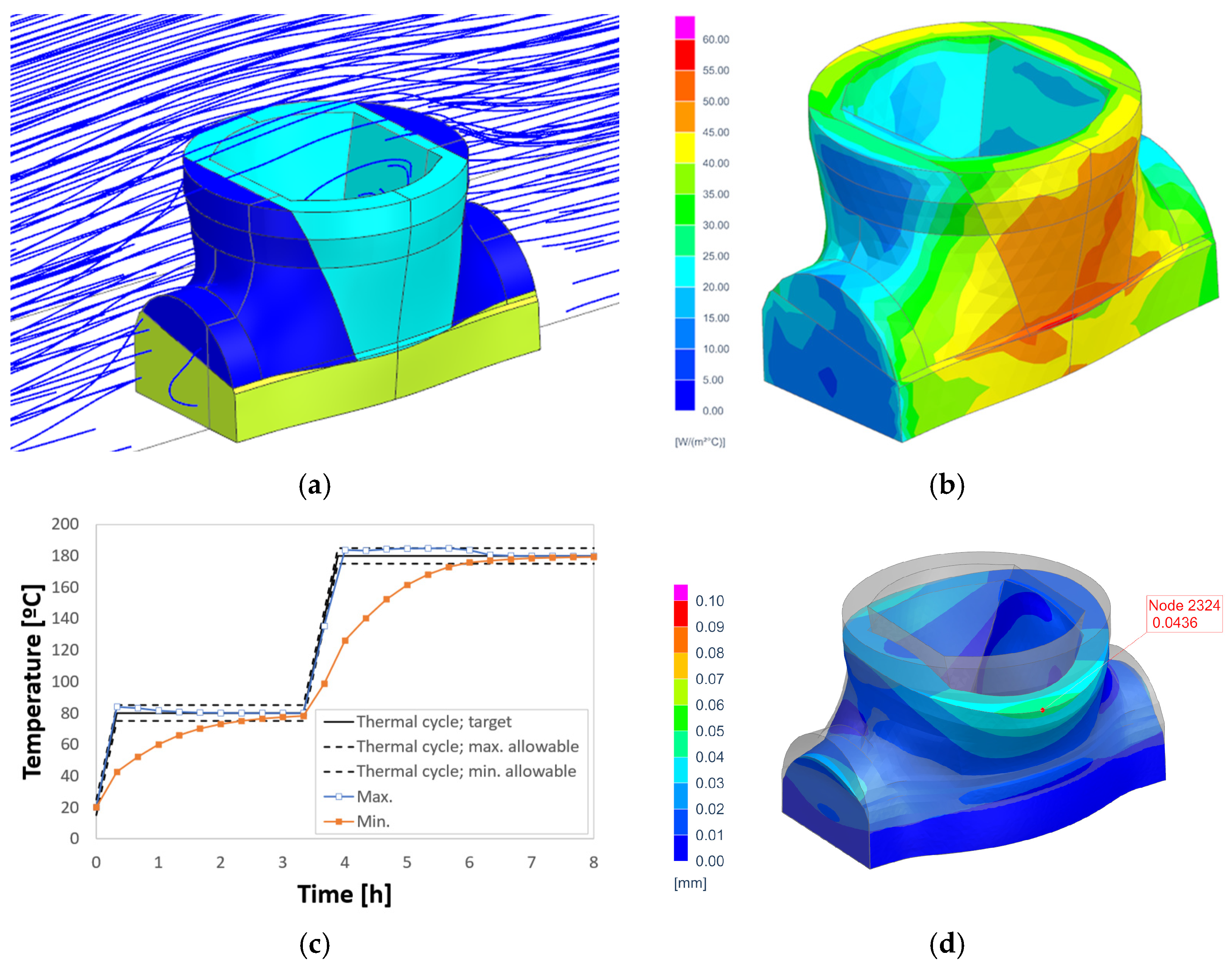
4.6. Result of the Computer Modelling of the Mould

As a result of several iterations, the design of the mould finally developed in this research paper is formed by four semi-moulds. The final mechanical design is shown in Figure 1 and Figure 13. Such a configuration ensures proper part extraction after the curing process. Moreover, the design drivers described in previous sections were applied for the development of this design. It is also remarkable that the simulations conducted during the iterative design process prove that some of the semi-moulds cannot be entirely solid to have a proper thermal response. The reasons for this are the quite heterogeneous distribution of the convection coefficients along the mould and the relatively low thermal diffusivity of the material. Therefore, a combination of solid and partially hollow (30% infill) semi-moulds is proposed instead. Concerning the assembly method, the central semi-mould is joined to the base part by means of two positioners, printed with the same material, while the external ones are joined through two rectangular pins. Regarding the printing strategy, every component is strategically printed to ensure a mould with homogeneous orthotropic properties once the semi-moulds are assembled. Scale factors of 98.2%, 98.2% and 96.6% are applied for the X, Y and Z directions, respectively. These factors are calculated bearing in mind the temperature- and pressure-induced deformations. The mass of the whole mould is lightened by around 90% with respect to the original invar design.
According to the numerical results, the streamlines predicted inside the autoclave (Figure 14a) involve a relatively heterogenous distribution of convection coefficients (Figure 14b). It is noticeable that the values obtained are in line with those published in the literature [65]. The heat exchange with the ambient temperature along the mould’s external faces is not uniform enough and might involve a heterogenous temperature contour. However, our results indicate that the strategic design of lateral semi-moulds, with internal infill volumes, enables proper thermal behaviour. Actually, even for the most demanding heating rates of 3 °C/min, an admissible delay of 2 h is foreseen between the hottest and coldest points to reach the curing temperature if a minimum dwell time of 3 h is completed (Figure 14c). The raw displacements, that is, the actual displacements that take place along the scaled mould due to the operating loads, are proven to mainly be a consequence of the temperature increase, as expected due to the high CTE of the material in the fibre-perpendicular direction. The scale factors applied to the mould are, however, able to compensate for the deformations well enough. Consequently, the determined displacement with respect the target geometry (net displacements) is proven to be low enough, lower than 0.1 mm, thus confirming that the mechanical requirements are fulfilled (Figure 14d). Our numerical results show a very low tensile state once the steady-state condition is reached (i.e., once the curing temperature is reached in the whole mould). However, quite high stresses are identified in the transient processes during the heating stages. It is numerically determined that the most unfavourable condition takes place at 4 h, when the maximum amounts of stress are reached. Based on the worst principal stresses in the printing direction and the material strength at corresponding temperatures (≈150 °C on average), an FoS of 2.8 is predicted. It can therefore be confirmed that the material can withstand the operating conditions with no risks.

5. Conclusions and Further Work

The printed pellet-based PA6 reinforced (20%) with short carbon fibre used in this research paper is found to be a suitable material to print preforms for the aeronautic moulding of aeronautic parts of composites, considering the design drivers established in the research.
The completed full experimental characterization allows the authors to determine the main properties concerning the thermoelastic performance of the material under operating conditions. The temperature dependency of the mechanical properties was characterized, and the complete results are available upon request. The experimental results include the tensile, compression, flexural and shear moduli and strength, both in the printing and the stacking directions and at room temperature, 80 °C and 180 °C. The influence of the temperature reduces the tensile strength in the printing bead direction from 37% to 70%; meanwhile, the tensile modulus decreases down to 56% and 71% at 80 °C and 180 °C, respectively. In the stacking direction, the tensile strength and modulus also decrease significantly. The effects of the printing machine and/or process parameters on the tensile moduli and strength, the porosity and the density are also analysed. Regarding the results of this study, the lower the porosity, the higher the tensile modulus and the tensile strength, whose values approach the tensile values of specimens processed by injection moulding. Comparing the tensile properties of injected BergamidTM B70 KF20 Black at room temperature, the moduli and strength can vary from 78% to 112% and from 55% to 87%, depending on the parameters and type of machine. The main properties regarding thermal response are characterized as well, and we found that the printed material is highly orthotropic, with different CTE values depending on whether the stacking or printing direction is used. In addition, due to the fact that the test specimens have been machined after the printing process, a good level of machinability was found, with surface roughness, Ra, values between 2.3388 and 3.496 µm. This work contributes to the literature by increasing our knowledge about the thermoelastic behaviour of printed carbon fibre-reinforced PA6.
Based on a real aeronautical application specified by the end user and thanks to its characterized properties, simulations that accurately reproduce the thermoelastic performance of the material under representative operating conditions are completed. In this sense, the conducted modelling activities allow the authors to iteratively design a 3D-printed mould for composite parts using pellets of carbon fibre-reinforced PA6. Moreover, the full design of the mould’s behaviour has been numerically validated in service. The mould is provn to be able to properly withstand both the curing temperature (180 °C) and the operating pressure (7 bar). A maximum net displacement of 0.04 mm is numerically determined, which is clearly lower than the maximum distortion required by the end user (0.10 mm). Moreover, it can ensure good temperature evolution and thermal uniformity along the lamination surface during the curing cycle. This suitable thermal performance is numerically predicted to continue even for the most demanding heating rates, in which the delay between the hottest and coldest points to reach the curing temperature matches the maximum delay required by the end user (2 h), if a minimum dwell time of 3 h is completed. Thanks to the advantages of this technology and the proposed material, the developed solution is 90% lighter than the original invar design. However, some potential problems that might occur in service for aeronautical moulds printed with this material are identified as well. These are basically related to the CTE, as the material is extremely orthotropic and very high in the fibre-perpendicular direction. In this work, the authors propose and successfully apply some design drivers to overcome these issues, which could be extended to different aeronautical moulds and sectors.
Taking into account that the mould will be fabricated using AMS II, a balance between the required time for printing the parts and the highest quality regarding the mechanical behaviour will determine the parameters for the final process.
Further work is planned concerning the research of moulds printed with PA6/CF6 in pellet form. Currently, semi-moulds based on the design presented in this paper are being printed through the AMS II extruder system, fed by pellets and installed at Tecnalia facilities. Once properly manufactured, it is planned to investigate methods for post-processing the laminate surface to ensure a smooth finish that is well-adjusted to the strict dimensional requirements before assembly. Afterwards, we plan to test the moulds under operating conditions to validate the proposed technology and material for the development of moulds for composite parts.

Supplementary Materials

The following supporting information can be downloaded at: https://www.mdpi.com/article/10.3390/jmmp8010034/s1, Supplementary Material S1: PolyMideTM PA6/CF. Supplementary Material S2: BergamidTM B70 KF20 Black.

Author Contributions

Conceptualization, J.C.A.-U. and E.B.R.; Data curation, J.G.L.; Formal analysis, H.V.A. and J.G.L.; Investigation, J.C.A.-U. and H.V.A.; Methodology, H.V.A.; Project administration, J.C.A.-U.; Software, H.V.A. and J.I.H.V.; Supervision, J.C.A.-U., H.V.A. and E.B.R.; Validation, E.B.R. and A.I.L.P.; Visualization, H.V.A., J.G.L. and J.I.H.V.; Writing—original draft, J.C.A.-U. and E.B.R.; Writing—review and editing, J.C.A.-U., H.V.A. and A.I.L.P. All authors have read and agreed to the published version of the manuscript.

Funding

This research was co-funded by EIT Manufacturing, code 22017.

Data Availability Statement

The data are available upon request due to restrictions, e.g., privacy or ethical reasons.

Acknowledgments

The work leading to this publication was co-funded by EIT Manufacturing under the code 22017. EIT Manufacturing is supported by the European Institute of Innovation and Technology (EIT), a body of the European Union. The views and opinions expressed herein are those of the author(s) only and do not necessarily reflect those of the European Union or EIT Manufacturing. Neither the European Union nor the EIT Manufacturing can be held responsible for them. Also, the authors would like to thank TECNALIA LabServices-Industry and other departments members, in particular, Urko Larramendi, David Villalta, Egoi Garmendia, Aitor Urbistondo, Xabier Cruz, Mariasun Mendizabal, Naiara Azurmendi and Gorka Imbuluzqueta, who provided support and input throughout this research project.

Conflicts of Interest

Ana Isabel Luengo Pizarro was employed by Internacional de Composites S.A. The remaining authors declare that the research was conducted in the absence of any commercial or financial relationships that could be construed as a potential conflict of interest. The Internacional de Composites S.A. had no role in the design of the study; in the collection, analyses, or interpretation of data; in the writing of the manuscript, or in the decision to publish the results.

References

  1. Grankäll, T.; Hallander, P.; Petersson, M.; Åkermo, M. The true shape of composite cure tools. J. Manuf. Process. 2020, 59, 279–286. [Google Scholar] [CrossRef]
  2. Stewart, R. New mould technologies and tooling materials promise advances for composites. Reinf. Plast. 2010, 54, 30–36. [Google Scholar] [CrossRef]
  3. Hasan, Z. Chapter 1—Introduction. In Tooling for Composite Aerospace Structures; Hasan, Z., Ed.; Butterworth-Heinemann: Oxford, UK, 2020; pp. 1–19. ISBN 978-0-12-819957-2. [Google Scholar]
  4. Li, Y.; Xiao, Y.; Yu, L.; Ji, K.; Li, D. A review on the tooling technologies for composites manufacturing of aerospace structures: Materials, structures and processes. Compos. Part A Appl. Sci. Manuf. 2022, 154, 106762. [Google Scholar] [CrossRef]
  5. Galiana, J. Guías básicas para elección de material de útil de curado en autoclave para fabricar piezas de composite. CFRP vs. INVAR36. In Proceedings of the XII Congreso Nacional de Materiales Compuestos MATCOMP 2017, Donostia-San Sebastian, Spain, 21–23 June 2017; Asociación Española de Materiales Compuestos (AEMAC): Getafe, Spain, 2017. [Google Scholar]
  6. Adeniran, O.; Cong, W.; Aremu, A. Material design factors in the additive manufacturing of Carbon Fiber Reinforced Plastic Composites: A state-of-the-art review. Adv. Ind. Manuf. Eng. 2022, 5, 100100. [Google Scholar] [CrossRef]
  7. Garmendia, I.; Vallejo, H.; Osés, U. Composite Mould Design with Multiphysics FEM Computations Guidance. Computation 2023, 11, 41. [Google Scholar] [CrossRef]
  8. Materials & Processes: Tooling for Composites. Available online: https://www.compositesworld.com/articles/tooling (accessed on 4 August 2023).
  9. UNE-EN ISO/ASTM 52900:2021; Additive Manufacturing- General Principles- Fundamentals and Vocabulary. UNE-EN (Una Norma Española sobre Norma Europea): Madrid, Spain, 2021.
  10. Frazier, W.E. Metal Additive Manufacturing: A Review. J. Mater. Eng. Perform. 2014, 23, 1917–1928. [Google Scholar] [CrossRef]
  11. Lee, J.-Y.; An, J.; Chua, C.K. Fundamentals and applications of 3D printing for novel materials. Appl. Mater. Today 2017, 7, 120–133. [Google Scholar] [CrossRef]
  12. Tofail, S.A.M.; Koumoulos, E.P.; Bandyopadhyay, A.; Bose, S.; O’Donoghue, L.; Charitidis, C. Additive manufacturing: Scientific and technological challenges, market uptake and opportunities. Mater. Today 2018, 21, 22–37. [Google Scholar] [CrossRef]
  13. Yan, L. Wire and Arc Additive Manufacture (WAAM) Reusable Tooling Investigation. Master’s Thesis, Cranfield University, Cranfield, UK, 2013. [Google Scholar]
  14. Calignano, F.; Mercurio, V. An overview of the impact of additive manufacturing on supply chain, reshoring, and sustainability. Clean. Logist. Supply Chain 2023, 7, 100103. [Google Scholar] [CrossRef]
  15. Pignatelli, F.; Percoco, G. An application- and market-oriented review on large format additive manufacturing, focusing on polymer pellet-based 3D printing. Prog. Addit. Manuf. 2022, 7, 1363–1377. [Google Scholar] [CrossRef]
  16. Bi, X.; Huang, R. 3D printing of natural fiber and composites: A state-of-the-art review. Mater. Des. 2022, 222, 111065. [Google Scholar] [CrossRef]
  17. Abderrafai, Y.; Diouf-Lewis, A.; Sosa-Rey, F.; Farahani, R.D.; Piccirelli, N.; Lévesque, M.; Therriault, D. Additive manufacturing and characterization of high temperature thermoplastic blends for potential aerospace applications. Compos. Sci. Technol. 2023, 231, 109839. [Google Scholar] [CrossRef]
  18. Dey, A.; Eagle, I.N.R.; Yodo, N. A review on filament materials for fused filament fabrication. J. Manuf. Mater. Process. 2021, 5, 69. [Google Scholar] [CrossRef]
  19. Spoerk, M.; Holzer, C.; Gonzalez-Gutierrez, J. Material extrusion-based additive manufacturing of polypropylene: A review on how to improve dimensional inaccuracy and warpage. J. Appl. Polym. Sci. 2020, 137, 48545. [Google Scholar] [CrossRef]
  20. Saroia, J.; Wang, Y.; Wei, Q.; Lei, M.; Li, X.; Guo, Y.; Zhang, K. A review on 3D printed matrix polymer composites: Its potential and future challenges. Int. J. Adv. Manuf. Technol. 2020, 106, 1695–1721. [Google Scholar] [CrossRef]
  21. Zhuo, P.; Li, S.; Ashcroft, I.A.; Jones, A.I. Material extrusion additive manufacturing of continuous fibre reinforced polymer matrix composites: A review and outlook. Compos. Part B Eng. 2021, 224, 109143. [Google Scholar] [CrossRef]
  22. Patel, A.; Taufik, M. Extrusion-Based Technology in Additive Manufacturing: A Comprehensive Review. Arab. J. Sci. Eng. 2022, 225, 111505. [Google Scholar] [CrossRef]
  23. Hassen, A.A.; Lindahl, J.; Chen, X.; Post, B.; Love, L.; Kunc, V. Additive Manufacturing of Composite Tooling using High Temperature Thermoplastic Materials. In Proceedings of the Society for the Advancement of Material and Process Engineering, Long Beach, CA, USA, 23–26 May 2016; North America Society for the Advancement of Material and Process Engineering (SAMPE): Diamond Bar, CA, USA. [Google Scholar]
  24. Park, S.J.; Lee, J.E.; Park, J.; Lee, N.K.; Son, Y.; Park, S.H. High-temperature 3D printing of polyetheretherketone products: Perspective on industrial manufacturing applications of super engineering plastics. Mater. Des. 2021, 211, 110163. [Google Scholar] [CrossRef]
  25. Ajinjeru, C.; Kishore, V.; Liu, P.; Lindahl, J.; Hassen, A.A.; Kunc, V.; Post, B.; Love, L.; Duty, C. Determination of melt processing conditions for high performance amorphous thermoplastics for large format additive manufacturing. Addit. Manuf. 2018, 21, 125–132. [Google Scholar] [CrossRef]
  26. Oberlercher, H.; Heim, R.; Laux, M.; Berndt, A.; Becker, C.; Amancio-Filho, S.T.; Riemelmoser, F.O. Additive manufacturing of continuous carbon fiber reinforced polyamide 6: The effect of process parameters on the microstructure and mechanical properties. Procedia Struct. Integr. 2021, 34, 111–120. [Google Scholar] [CrossRef]
  27. Shashikumar, S.; Sreekanth, M.S. The effect of printing parameters on tensile properties of thermoplastics prepared by fused deposition modeling (FDM) based additive manufacturing technique. Mater. Today Proc. 2023, 90, 256–261. [Google Scholar] [CrossRef]
  28. Chesser, P.; Post, B.; Roschli, A.; Carnal, C.; Lind, R.; Borish, M.; Love, L. Extrusion control for high quality printing on Big Area Additive Manufacturing (BAAM) systems. Addit. Manuf. 2019, 28, 445–455. [Google Scholar] [CrossRef]
  29. Love, L.J.; Duty, C.E.; Post, B.K.; Lind, R.F.; Lloyd, P.D.; Kunc, V.; Peter, W.H.; Blue, C.A. Breaking Barriers in Polymer Additive Manufacturing. In SAMPE 2015; SAMPE North America: Baltimore, MD, USA, 2015. [Google Scholar]
  30. Post, B.K.; Richardson, B.; Lind, R.; Love, L.J.; Lloyd, P.; Kunc, V.; Rhyne, B.J.; Roschli, A.; Hannan, J.; Nolet, S.; et al. Big Area Additive Manufacturing application in wind turbine molds. In Proceedings of the 28th Annual International Solid Freeform Fabrication Symposium—An Additive Manufacturing Conference, SFF 2017, Austin, TX, USA, 7–9 August 2017; pp. 2430–2446. [Google Scholar]
  31. Roschli, A.; Gaul, K.T.; Boulger, A.M.; Post, B.K.; Chesser, P.C.; Love, L.J.; Blue, F.; Borish, M. Designing for Big Area Additive Manufacturing. Addit. Manuf. 2019, 25, 275–285. [Google Scholar] [CrossRef]
  32. Sher, D. WHAM, There’s a New “Largest 3D Printer in the World” in Town. Available online: https://www.voxelmatters.com/wham-theres-a-new-largest-composite-3d-printer-in-the-world-in-town/ (accessed on 7 August 2023).
  33. Thompson, W.; Huelskamp, S.R.; Allessio, T.; Ly, K. Large-Format Additive Manufacturing: Viable for Autoclave Tooling? Available online: https://www.additivemanufacturing.media/articles/large-format-additive-manufacturing-viable-for-autoclave-tooling (accessed on 7 August 2023).
  34. Chambon, P.; Curran, S.; Huff, S.; Love, L.; Post, B.; Wagner, R.; Jackson, R.; Green, J. Development of a range-extended electric vehicle powertrain for an integrated energy systems research printed utility vehicle. Appl. Energy 2017, 191, 99–110. [Google Scholar] [CrossRef]
  35. Curran, S.; Chambon, P.; Lind, R.; Love, L.; Wagner, R.; Whitted, S.; Smith, D.; Post, B.; Graves, R.; Blue, C.; et al. Big Area Additive Manufacturing and Hardware-in-the-Loop for Rapid Vehicle Powertrain Prototyping: A Case Study on the Development of a 3-D-Printed Shelby Cobra. In SAE 2016 World Congress and Exhibition; SAE International: Warrendale, PA, USA, 2016. [Google Scholar]
  36. Moreno Nieto, D.; Casal López, V.; Molina, S.I. Large-format polymeric pellet-based additive manufacturing for the naval industry. Addit. Manuf. 2018, 23, 79–85. [Google Scholar] [CrossRef]
  37. Post, B.; Chesser, P.; Lind, R.; Sallas, M.; Love, L.J. Feasibility of Using Big Area Additive Manufacturing to Directly Manufacture Boat Molds; Final Report NN-17-1062; Oak Ridge National Laboratory: Oak Ridge, TN, USA, 2018.
  38. Wahlström, N.; Gabrielsson, O. Additive Manufacturing Applications for Wind Turbines. Master of Science Thesis, KTH Industrial Engineering and Management, Stockholm, Sweden, 2017. [Google Scholar]
  39. Post, B.K.; Richardson, B.; Lloyd, P.; Love, L.J.; Nolet, S.; Hannan, J. Additive Manufacturing of Wind Turbine Molds; CRADA Final Report NFE-16-06051; Oak Ridge National Labnoratory: Oak Ridge, TN, USA, 2017; ISBN 1800553684.
  40. Silva, M.R.; Pereira, A.M.; Alves, N.; Mateus, G.; Mateus, A.; Malça, C. Development of an additive manufacturing system for the deposition of thermoplastics impregnated with carbon fibers. J. Manuf. Mater. Process. 2019, 3, 35. [Google Scholar] [CrossRef]
  41. Peng, X.; Zhang, M.; Guo, Z.; Sang, L.; Hou, W. Investigation of processing parameters on tensile performance for FDM-printed carbon fiber reinforced polyamide 6 composites. Compos. Commun. 2020, 22, 100478. [Google Scholar] [CrossRef]
  42. Zhuo, P.; Li, S.; Ashcroft, I.A.; Jones, A.I. Continuous fibre composite 3D printing with pultruded carbon/PA6 commingled fibres: Processing and mechanical properties. Compos. Sci. Technol. 2022, 221, 109341. [Google Scholar] [CrossRef]
  43. Li, X.; He, J.; Hu, Z.; Ye, X.; Wang, S.; Zhao, Y.; Wang, B.; Ou, Y.; Zhang, J. High strength carbon-fiber reinforced polyamide 6 composites additively manufactured by screw-based extrusion. Compos. Sci. Technol. 2022, 229, 109707. [Google Scholar] [CrossRef]
  44. Li, L.; Liu, W.; Sun, L. Mechanical characterization of 3D printed continuous carbon fiber reinforced thermoplastic composites. Compos. Sci. Technol. 2022, 227, 109618. [Google Scholar] [CrossRef]
  45. Polymaker Technical Data Sheet—PolyMideTM PA6-CF. Available online: https://filament2print.com/es/index.php?controller=attachment&id_attachment=414 (accessed on 13 April 2023).
  46. Avient Technical Data Sheets. Available online: https://www.avient.com/resources/technical-data-sheets (accessed on 13 April 2023).
  47. Tagscherer, N.; Bär, A.M.; Zaremba, S.; Drechsler, K. Mechanical Analysis of Parameter Variations in Large-Scale Extrusion Additive Manufacturing of Thermoplastic Composites. J. Manuf. Mater. Process. 2022, 6, 36. [Google Scholar] [CrossRef]
  48. Al-Maharma, A.Y.; Patil, S.P.; Markert, B. Effects of porosity on the mechanical properties of additively manufactured components: A critical review. Mater. Res. Express 2020, 7, 122001. [Google Scholar] [CrossRef]
  49. Yang, C.; Tian, X.; Li, D.; Cao, Y.; Zhao, F.; Shi, C. Influence of thermal processing conditions in 3D printing on the crystallinity and mechanical properties of PEEK material. J. Mater. Process. Technol. 2017, 248, 1–7. [Google Scholar] [CrossRef]
  50. Antolín-Urbaneja, J.C.; Bengoa Ganado, P.; Mateu, A.; Fernández Valares, J.B.; Hernandez Vicente, J.; Bellvert Rios, E.; Vallejo Artola, H.; Alberdi Olaizola, N.; Pacheco Goñi, R.; Luengo Pizarro, A.I. Automated MOLDAM Robotic System for 3D printing: Manufacturing aeronautical mould preforms. In V International Congress on Computer Science, Electronic and Industrail Engineering (CSEI); Universidad Técnica de Ambato, Facultad de Ingeniería en Sistemas, Electrónica e Industrial: Ambato, Ecuador, 2023. [Google Scholar]
  51. Ly, K.; Thompson, W.; Voorde, D. Evaluating the printability and Mechanical Properties of LFAM Regrind. Available online: https://www.additivemanufacturing.media/articles/evaluating-the-printability-and-mechanical-properties-of-lfam-regrind (accessed on 1 February 2023).
  52. ISO 4287:1997; Geometrical Product Specifications (GPS). Surface Texture: Profile Method. ISO (International Organization for Standardization): Geneva, Switzerland, 1997.
  53. ISO 527-1; Plastics—Determination of Tensile Properties—Part 1: General Principles. ISO (International Organization for Standardization): Geneva, Switzerland, 2019.
  54. ISO 527-2:2012; Plastics—Determination of Tensile Properties—Part 2: Test Conditions for Moulding and Extrusion Plastics. ISO (International Organization for Standardization): Geneva, Switzerland, 2012.
  55. ISO 14125:1998/Amd 1:2011; Fibre-Reinforced Plastic Composites—Determination of Flexural Properties (Amendment 1). ISO (International Organization for Standardization): Geneva, Switzerland, 2011.
  56. ISO 604:2022; Plastics—Determination of Compressive Properties. ISO (International Organization for Standardization): Geneva, Switzerland, 2022.
  57. ASTM D5379/D5379M-19e1; Standard Test Method for Shear Properties of Composite Materials by the V-Notched Beam Method. ASTM International (American Society for Testing and Materials): West Conshohocken, PA, USA, 2021.
  58. ISO6721-1:2019; Plastics. Determination of Dynamic Mechanical Properties. Part1: General Principles. ISO (International Organization for Standardization): Geneva, Switzerland, 2019.
  59. ISO 22007-2:2016; Plastics—Determination of Thermal Conductivity and Thermal Diffusivity—Part 2: Transient Plane Heat Source (Hot Disc) Method. ISO (International Organization for Standardization): Geneva, Switzerland, 2016.
  60. UNE-EN ISO 1183-1:2019; Plastics—Methods for Determining the Density of Non-Cellular Plastics—Part 1: Immersion Method, Liquid Pycnometer Method and Titration Method (ISO 1183-1:2019, Corrected Version 2019-05). UNE-EN (Una Norma Española sobre Norma Europea): Madrid, Spain, 2019.
  61. UNE-EN ISO 4288:1998; Geometrical Product Specifications (GPS). Surface Texture: Profile Method- Rules and Procedures for the Assessment of Surface Texture. UNE-EN (Una Norma Española sobre Norma Europea): Madrid, Spain, 1998.
  62. Brinson, H.F.; Brinson, L.C. Time and Temperature Behavior of Polymers. In Polymer Engineering Science and Viscoelasticity: An Introduction; Springer: Boston, MA, USA, 2008; pp. 221–274. ISBN 978-0-387-73861-1. [Google Scholar]
  63. Valino, A.D.; Dizon, J.R.C.; Espera, A.H.; Chen, Q.; Messman, J.; Advincula, R.C. Advances in 3D printing of thermoplastic polymer composites and nanocomposites. Prog. Polym. Sci. 2019, 98, 101162. [Google Scholar] [CrossRef]
  64. Park, J.; Zobeiry, N.; Poursartip, A. Tooling materials and their effect on surface thermal gradients. In Proceedings of the International SAMPE Technical Conference, Seattle, WA, USA, 22–26 May 2017; pp. 2554–2568. [Google Scholar]
  65. ASTM E562-19e1; Standard Test Method for Determining Volume Fraction by Systematic Manual Point Count. ASTM International (American Society for Testing and Materials): West Conshohocken, PA, USA, 2020.
Figure 1. Complete designed mould with finite element analysis guidance.
Jmmp 08 00034 g001
Figure 2. Working methodology for the development of the 3D-printed mould preform for the manufacturing of aeronautical composite parts using pellets of carbon fibre-reinforced PA6.
Jmmp 08 00034 g002
Figure 3. Illustration of the designed square cube to obtain the test specimens for characterization. Example of test probes.
Jmmp 08 00034 g003
Figure 4. Square cube manufactured with RAMS to obtain the test specimens from named walls (left) and MOLDAM additive manufacturing system for printing parts (right).
Jmmp 08 00034 g004
Figure 5. Machined specimens for tensile (left) and flexural tests (right).
Jmmp 08 00034 g005
Figure 6. Specimens manufactured with RAMS during (a) tensile, (b) compression, (c) flexural, (d) shear and host-disc tests for the characterization of (e) specific heat and (f) thermal conductivity.
Jmmp 08 00034 g006aJmmp 08 00034 g006b
Figure 7. Meshes for the thermal flow (a) and mechanical (b) simulations. Note that the mesh regarding the internal air is moved upwards to improve the visualization of the internal meshes.
Jmmp 08 00034 g007
Figure 8. Comparison of the tensile moduli and strengths in the printing bead direction and stacking direction depending on the temperature using printed Bergamid B70 KF20 Black.
Jmmp 08 00034 g008
Figure 9. Comparison of the tensile moduli and strengths in the printing bead direction depending on the machines and/or parameters used for the manufacturing of samples with those for Bergamid B70 KF20 Black.
Jmmp 08 00034 g009
Figure 10. Macrograph of the deposited profile obtained via 3D printer (RAMS).
Jmmp 08 00034 g010
Figure 11. Macrographs of the each case in our study: RAMS (a), AMSI (b), AMSII (1) (c) and AMSII (2) (d), showing the profile of the printed beads and the porosity.
Jmmp 08 00034 g011aJmmp 08 00034 g011b
Figure 12. Micrographs of the first representative field for each case in our study: RAMS (upper left), AMS I (upper right), AMS II (1) (bottom left) and AMS II (2) (bottom right), showing the greatest carbon fibre length and porosity.
Jmmp 08 00034 g012
Figure 13. Cut view of the complete designed mould according to Figure 1.
Jmmp 08 00034 g013
Figure 14. (a) Air streamlines around the mould, (b) resulting convection coefficients at 180 °C, (c) evolution of the maximum and minimum temperatures at the lamination surface (3 °C/min, 3 h at 80 °C) and (d) net displacement contour under maximum operating conditions.
Jmmp 08 00034 g014
Table 1. Mechanical properties of two different polyamides reinforced with 20% CF.
Product #1 [45]Product #2 [46]
MaterialPolyMideTM PA6/20CF
(Supplementary Material S1)
BergamidTM B70 KF20 Black
(Supplementary Material S2)
ManufacturerPolymaker (Shangai, China)Avient Corporation (Barbastro, Spain)
Form of materialFilamentPellet
Processing methodFDMInjection Molding
Tensile moduli (X-Y)—GPa 7.513.8
Tensile moduli (Z)—GPa4.4-
Tensile strength (X-Y)—MPa105220
Tensile strength (Z)—MPa 68-
Density—kg/m311701210–1250
Table 3. Main characteristics of the machines and parameters used to manufacture samples for the experimental characterization.
ParameterRAMSAMS IAMS II (1)AMSII (2)
Extruder Type20XDPulsar20XD20XD
Nozzle Diameter (mm)4388
Theoretical Bead Width (mm)53.688
Theoretical Bead Height (mm)1.51.54 2
Maximum Mass Flow (kg/h)302.53030
Extruder Temperature (°C)
1. Feed210220190190
2. Zone 2 (Middle)230235200200
3. Nozzle240250235235
Bed Temperature (°C)RT1109090
Barrel Length (mm)720300720720
Print Speed (mm/s)35353535
Table 4. Theoretical and measured bead height and width versus additive manufacturing.
Bead Height and WidthRAMSAMS I AMS II (1)AMSII (2)
Theoretical Bead Width (mm)53.688
Bead Width Mean, m (mm)4.704.168.098.01
Bead Width Deviation (mm)0.080.370.210.17
Theoretical Bead Height (mm)1.51.542
Bead Height Mean, n (mm)1.481.473.871.92
Bead Height Deviation (mm)0.040.150.070.15
B. Height Error vs. Theoretical (%)1.332.003.254.00
B. Width Error vs. Theoretical (%)5.9615.441.080.12
Table 5. Results of the estimated porosity for each type of specimen.
Porosity RAMSAMS I AMS II (1)AMS II (2)
(A1) Area #1 (%)4.56.731.571.09
(A2) Area #2 (%)4.953.212.291.35
(A3) Area #3 (%)4.478.552.630.43
(A4) Area #4 (%)4.39.771.380.5
(A5) Area #5 (%)4.573.73.840.34
Mean Value (%)4.66.42.30.7
Standard Deviation 0.22.910.4
Confidence interval 95%0.33.61.20.6
Relative Accuracy (RA %)6.656.35275.2
Table 6. Density of the printed material versus machine.
Density RAMSAMS I AMS II (1)AMSII (2)
X length (mm)30.1330.1730.2230.14
Y width (mm)29.9830.1530.0730.09
Z height (mm)2.782.813.423.97
Weight (g)2.8422.9913.6434.334
Geometrical- ρ (g/cm3)1.1321.1701.1721.204
Archimedes- ρ (g/cm3)1.121.171.21.19
Table 7. Identification of the potential problems versus design drivers.
Potential ProblemDesign Strategy
Severe problems of CTE mismatch. Avoid the use of dissimilar materials.
Strategically print the semi-moulds and the joining elements to have uniform thermal expansion in each direction.
Large temperature-induced displacements.Accurately determine and apply specific scale factors to compensate for the displacements.
Large pressure-induced displacements. Manufacture solid semi-moulds as a general rule.
Accurately determine and apply specific scale factors to compensate for the displacements.
Excessive thermal gradients on the lamination surface. In case of a poor thermal performance, print partially hollow semi-moulds with infill volumes.
Disclaimer/Publisher’s Note: The statements, opinions and data contained in all publications are solely those of the individual author(s) and contributor(s) and not of MDPI and/or the editor(s). MDPI and/or the editor(s) disclaim responsibility for any injury to people or property resulting from any ideas, methods, instructions or products referred to in the content.

