1. Introduction
Cemented carbides are composite materials consisting of hard carbide particles embedded in a tough metallic binder phase. Due to their remarkable combination of hardness, wear resistance, and toughness, they have become the primary material choice for extreme applications as tools and components in diverse industries, including machining, drilling, and mining [
1]. In general, a grinding process is performed after sintering to achieve the necessary macro-geometry [
2]. However, the resulting surface quality usually does not meet final micro-geometry or mechanical requirements, which are critical for cutting tools. Hence, further finishing operations on these tools are mandatory, particularly regarding their cutting edges, in order to improve their performance and extend their service life.
Generally, post-grinding finish operations not only optimize the shape and size of a cutting edge, but also increase the wear resistance of a tool [
3,
4] by reducing pre-existing defects and enhancing both its mechanical [
5] and adhesion strength in the case of coated tools [
6]. In addition, higher edge quality lessens the stress concentration between the tool and the workpiece, resulting in a uniform distribution of loads. This slows a cutting edge’s wear [
7], chipping formation during cutting [
8], and the temperature achieved [
9]. Moreover, cutting edge preparation is used to minimize compressive residual stresses, providing a smooth surface for post-coating the desired end-mills [
6].
However, it is well known that radius parameter is not enough to characterize the micro-geometry of a cutting tool. In that sense, the
K-factor, which is defined as the ratio between rake and clearance surfaces (
Sγ/
Sα), plays an important role [
5]. The
K-factor dictates the micro-geometry of a cutting tool, with three options available: symmetric, waterfall, and reverse waterfall (also referred to as trumpet), depending on whether
K is equal to, less than, or greater than one, respectively [
10].
Over the past decade, numerous investigations have addressed the influence of a cutting edge’s micro-geometry on tool wear and its thermo-mechanical load under service-like working conditions [
5,
11,
12]. However, information regarding the direct effect of the
K-factor form on end-mills is scarce, and is somehow limited to tool life maps, also known as Taylor lines. Furthermore, the highest tool lifespans reported were found for
K-factor values higher or lower than one, depending on whether the material machined by the hardmetal tool was Inconel 718 or a Ti-alloy, respectively [
11]. Contrary to these findings, Denkena et al. [
5] reported that the durability of cemented carbide tools when machining AISI 1045 is not dependent on the
K-factor. Additionally, cemented carbide inserts show increased durability when exposed to static or dynamic thermo-mechanical loads, with cutting edge
K-factors of approximately < 1 and >1, respectively [
11].
Numerous advanced preparation methods have been developed to perform chamfering, honing, and radius modification, such as electrical discharge machining, laser machining, magneto abrasive machining, abrasive jet machining, brushing, and drag finishing. However, the last three methods are the most commonly used techniques in the cemented carbides industry [
3,
5,
7]. These techniques aim to reach an optimal cutting edge radius and minimize detrimental effects like edge chipping, high cutting forces, and poor surface finish, while simultaneously enhancing chip evacuation and reducing tool wear [
5,
7,
13,
14]. However, although these techniques allow modification of the micro-geometry of tools, they also present specific limitations. Abrasive jet machining removes the metallic cobalt (Co) binder from the surface, decreasing tools’ mechanical integrity [
15]. Brushing is limited to producing edge rounding for complex geometries, and it results in elevated temperatures during the conditioning process [
9]. Drag finishing is more time-consuming than previous methods, depending on the desired radius. Furthermore, the sizes of abrasive particles pose limitations for small geometries, and are less flexible, as the entire piece is submerged in the abrasive [
5].
Based on the above ideas, research regarding new technologies to address preparation challenges associated with cutting edges is required. Therefore, this study examined the dry-electropolishing technique to fulfil all requirements related to cutting edges’ preparation to enhance the lifetime of cutting tools. This method is based on ion exchange resins interacting with roughness peaks [
16]. On cemented carbide materials, this effective polishing action takes place particularly at the cutting edge, where selective roughness is removed until the desired radius is attained, while compressive residual stresses produced during the machining process are preserved [
16]. In this sense, the technology employed removes only the minimum amount of material by interacting solely with roughness peaks. This results in a cost-saving advantage compared to existing industrial methods because it preserves the tolerances of the workpiece as well as maintains the stress field induced during the pre-processing stage. Additionally, the resulting microstructure is free of corrosion, reaching a nearly flat surface between constitutive phases.
This research aimed to develop a preparation protocol for cutting edges, taking into account key micro-geometry parameters and characterizing the evolution of defects located at cutting edges as a function of dry-electropolishing time.
2. Materials and Methods
This investigation was conducted on an end-mill made of WC-Co cemented carbide material with 6 wt. % of a metallic Co binder and a fine microstructure. The final shape, geometry, and tolerances of the entire end-mill were obtained by applying a grinding process after sintering. Grinding was carried out using a commercial diamond grinding wheel. Coolant was used to prevent heat generation.
The end-mill was dry-electropolished (using DryLyte
® Technology, Steros GPA Innovative, Barcelona, Spain) with a commercial electrolyte. Further and detailed information can be found in [
16]. The end-mill was processed to a maximum of 30 min. Two different time sets of dry-electropolishing time were utilized until the maximum investigated time was reached: (1) initially ranging from 0 to 120 s, every 30 s, to assess the efficiency of the dry-electropolishing process in its early stages, and (2) subsequently at 3, 5, 10, 20, and 30 min to monitor how geometrical and microstructural parameters evolved as a function of time.
The initial end-mill was evaluated in terms of macro- and micro-geometry, radius (
r), and surface average roughness (
Ra) parameters (
Table 1). In doing so, these initial cutting edges’ parameters and roughness values, as well as their evolution at each polishing stage, were assessed using a focus variation laser scanning microscope (LSM) (EdgeMaster X module—Bruker Alicona, Gratz, Austria). The
Ra of the clearance was obtained in accordance with ISO 4287 (cut-off = 0.25 mm).
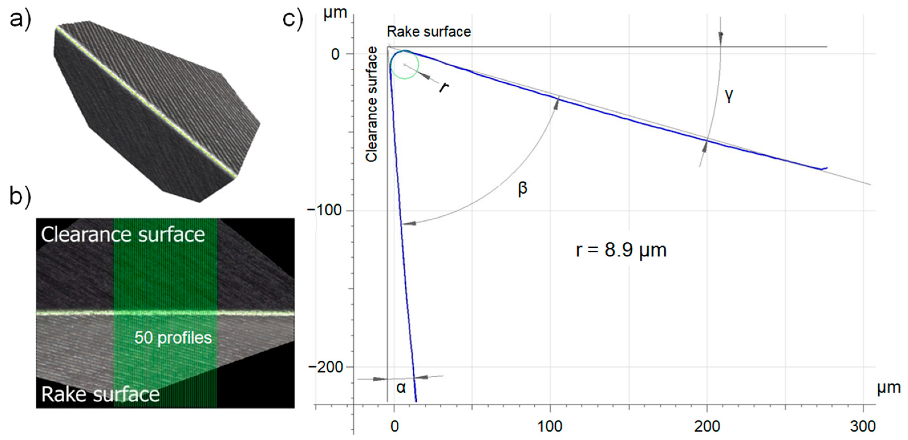
To better understand the main cutting parameters, a 3D reconstruction of the end-mill and a schematic representation of the micro-geometry of the cutting edge’s profile (accomplished using an InfiniteFocus G5 plus—Bruker Alicona, Gratz, Austria) are presented in
Figure 1a,b, respectively. To obtain statistical significance, 3D measurements were conducted on multiple profiles with 50 cutting edges (
Figure 2).
Microstructural characterization was performed before and after each dry-electropolishing step by means of field emission scanning electron microscopy (FE-SEM, Carl Zeiss Neon 40, Zeiss Group, Oberkochen, Germany).
3. Results
Before polishing, pre-existing defects of the end-mill were analyzed.
Figure 3 corresponds to FE-SEM micrographs of primary pre-existing defects found in the unprepared end-mill—specifically burrs (
Figure 3a) and chipping (
Figure 3b). These damage features were caused during the post-sintering grinding process. Such defects are primarily responsible for reducing tool life under service-like working conditions; hence, it is mandatory to improve cutting edges’ quality and minimize defects to improve tool performance [
2,
5].
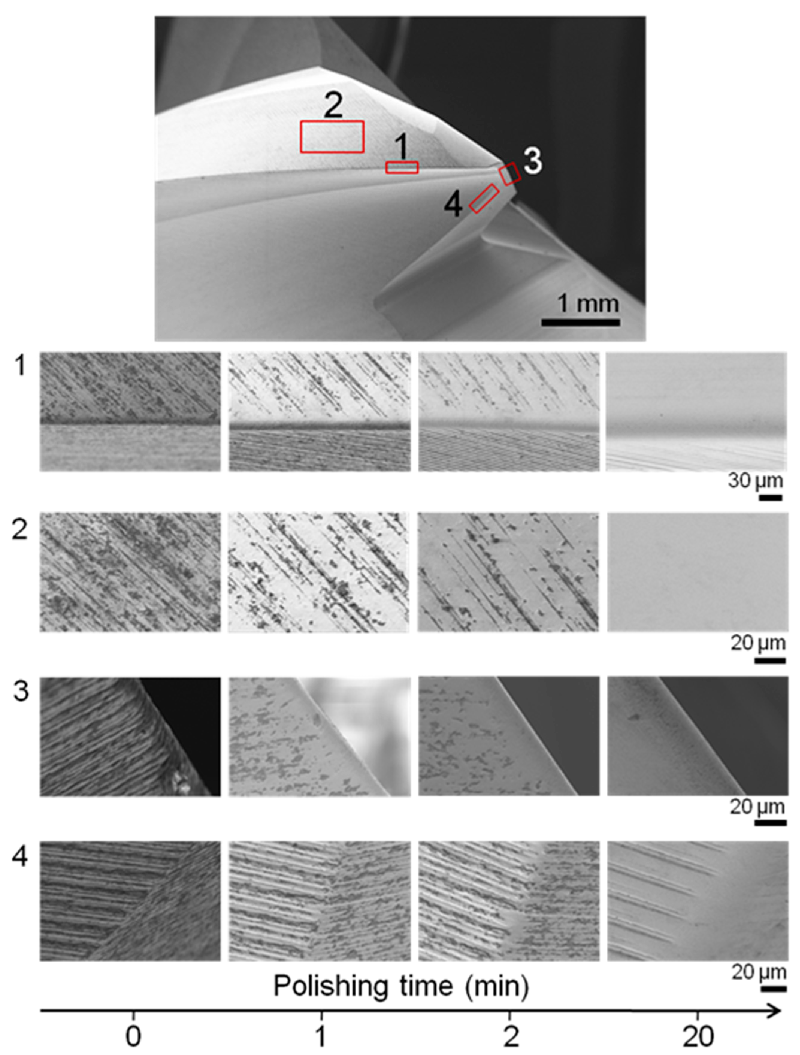
Figure 4 displays microstructural changes in four distinct investigated areas (red rectangles in the upper image) before and after the dry-electropolishing procedure. Initial defect density decreased with increased dry-electropolishing time. However, external regions corresponding to zones 1 to 3 (
Figure 4) exhibited a lower density of pre-existing damage as compared to the internal region (zone 4), as shown in
Figure 3. This may be attributed to two factors: (1) the greater mobility of the electrolyte on the outer regions, and (2) the proximity of the end-mill to the cathode. The simultaneous occurrence of both effects led to a higher effective material removal rate in external regions as compared to internal ones.
Figure 5 summarizes changes in
Ra as a function of time for the clearance face (region (2), as labelled in
Figure 4). Two distinct trends were identified, both of which follow a linear regression, as presented in Equations (1) and (2) for trends 1 and 2, respectively.
where
Ra and
t correspond to average roughness and dry-electropolishing time, respectively. The R-squared values associated with linear fit are 0.98 and 0.99 for Equation (1) and Equation (2), respectively.
The maximum reduction in Ra occurred during the first stage (trend 1), and was linked to the higher initial roughness achieved during pre-processing. At the beginning of processing, the electrolyte easily removed roughness due to the presence of pre-existing pronounced peaks. Afterwards, the roughness removal rate diminished (trend 2) at a polishing speed of 4.5 nm/min. In that sense, after eliminating the most prominent peaks, polishing progression decelerated.
For comparison purposes, in terms of
Ra,
Figure 6 shows the
Ra roughness profiles of the three main zones presented in
Figure 5: the initial state (
t = 0 min,
Figure 6a), the threshold between both trends (after 2 min,
Figure 6b), and when the
Ra was practically stable (after 30 min of the dry-electropolishing process,
Figure 6c). A ground lines reduction was clearly visible in these profiles, in agreement with SEM micrographs presented in
Figure 4.
After evaluating the microstructural parameters in terms of roughness and defects as a function of dry-electropolishing time, the micro-geometrical parameters of cutting edges were evaluated, and are summarized in
Figure 7.
According to Equation (3), which was derived after fitting experimental values shown in
Figure 7a, the radius increased exponentially as the polishing time increased. However, the growth rate did not conform to a linear trend, as it diminished slightly over time due to the rounding effect associated with the polishing process.
Therefore, it is feasible to regulate the final radius achieved by varying dry-electropolishing durations as:
where
r corresponds to the cutting edge’s radius. The R-square associated with the linear fit is 0.99.
Figure 7b,c exhibit the
K-factor and
Sα and
Sγ as functions of dry-electropolishing time, respectively. At short polishing times
Sα had a larger increase compared with
Sγ. However, after 3 min, it was possible to observe that both parameters (
Sα and
Sγ) reached a plateau, with the
Sα value slightly larger than the
Sγ value (
Figure 7c). As a result, the
K-factor stabilized and was equal to 0.75 ± 0.03, in agreement with findings reported by Droder et al. [
6]. Under these conditions, the cutting edge form obtained corresponded to a waterfall
K-factor, becoming more constant as the process time increased.


