1. Introduction
The protection of the environment and the natural resources as well as the tackling of climate change are challenging issues for the manufacturing industry. Hence, new industrial solutions that enable reductions in CO
2 emissions and energy consumption have to be found [
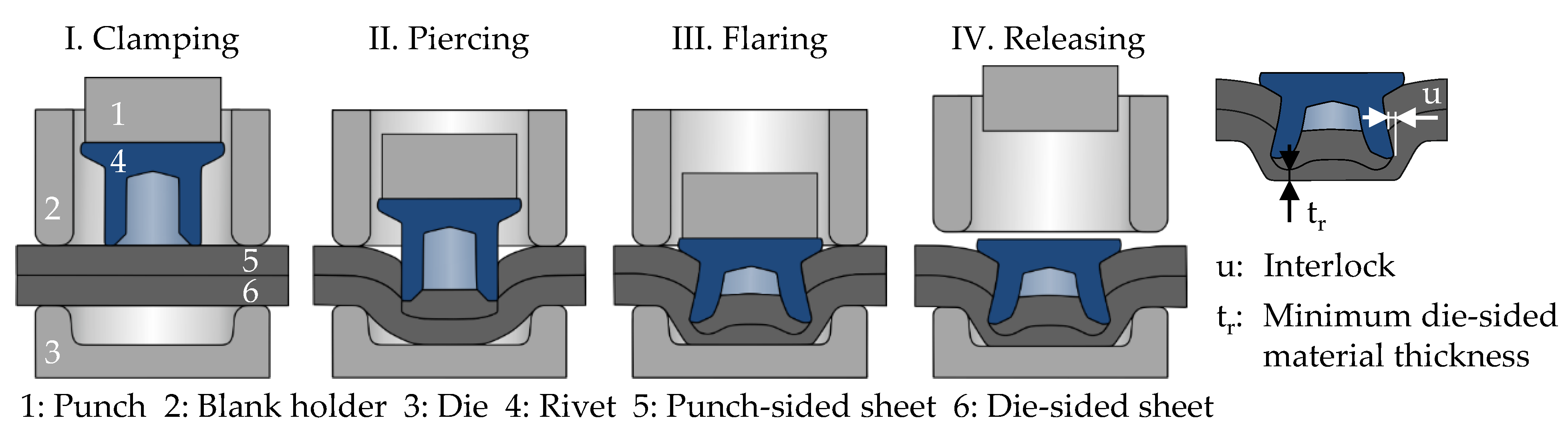
1]. To reach a reduction in emissions in car traffic, using the lightweight design of car bodies is an established method. The lightweight design causes an increasing use of multi-material structures made of high-strength steel and aluminium. To join these materials, mechanical joining techniques like the self-piercing riveting (SPR) technique are emerging. The process stages of SPR and the characteristic joint parameters are shown in
Figure 1. The rivet is pressed into the clamped sheets and pierces the punch-sided material. After that, the rivet flares, and an interlock is created within the die-sided sheet. The interlock is the most important property of the joint because it is an indicator for the expectable joint strength [
2]. In contrast to the previously established resistance spot welding, mechanical joining technologies like self-piercing riveting do not require heating of the joining parts so that energy during car body manufacturing can be saved [
3]. Moreover, the joining of different kinds of sheet materials is possible with self-piercing riveting. However, for SPR, the rivet is needed, which causes an expense in costs and energy consumption [
4]. Clinching can be conducted without an additional fastener. Nevertheless, the application area of clinching is limited to low material strengths under a tensile strength of 1000 MPa [
5]. SPR, instead, is feasible for a broad material range, even for ultra-high strength sheet materials with a tensile strength of 2000 MPa [
6]. Furthermore, the joint strength of self-piercing riveted joints is normally higher than that with clinched and welded joints [
7]. This is why SPR is used for the joining in car body areas with crash requirements, whereas clinching is used for non-load-bearing structures [
4]. The joining result with the self-piercing riveting depends on the rivet and the die, which are selected in accordance with the strength, the ductility and the thickness of the sheets to be joined [
8]. The rivets for SPR differ in geometry, material and surface condition. As a function of the materials used for car bodies, several different rivet geometries were developed in the past. Due to the challenges when joining high-strength steel, especially on the die side, the authors have designed a new rivet geometry for the joining of two challenging material combinations consisting of high-strength HCT780X steel and EN AW-5083 aluminium in former studies [
9]. Based on this rivet geometry, an innovative rivet with special properties and a completely new approach of the rivet manufacturing process are developed, as explained within this paper.
2. Approach for a Sustainable Process Chain
A holistic view of the process chain related to SPR refers not only to the joining process itself, but also includes the entire life cycle from the material production process to the use of the finally joined components, as illustrated in
Figure 2.
There is a great potential to improve the process efficiency and sustainability of the rivet manufacturing process in particular. Rivets are generally made out of high-strength boron steels [
8] and are formed in multistage cold forming processes [
12]. To ensure an adequate strength and a good corrosion resistance, the rivets must be heat-treated and coated after the rivet forming process [
13], which makes the entire rivet production time-consuming, energy-intensive and costly. The heat treatment process, more precisely the hardening and tempering of the rivets, is especially energy-intensive. Unfortunately, the authors have no insights into the energy and cost structure of the manufacturing companies. This is why only a qualitative evaluation with regard to the rivet manufacturing process is possible. However, it is known from [
14] that about 40% of the energy that is used in the industrial environment in Germany is attributed to heat treatment processes. This is underpinned by the results of a scientific analysis carried out by Mendikoa et al. [
15] concerning the energy consumption of a steel foundry, which reveals that more than a third of the total gas of the company is consumed due to the heat treatment. As a logical consequence, there is a need to avoid the heat treatment of cold-formed components. Considering, in addition, the wide use of mechanical joining operations and the rising energy prices, a more sustainable and economical rivet manufacturing process is needed.
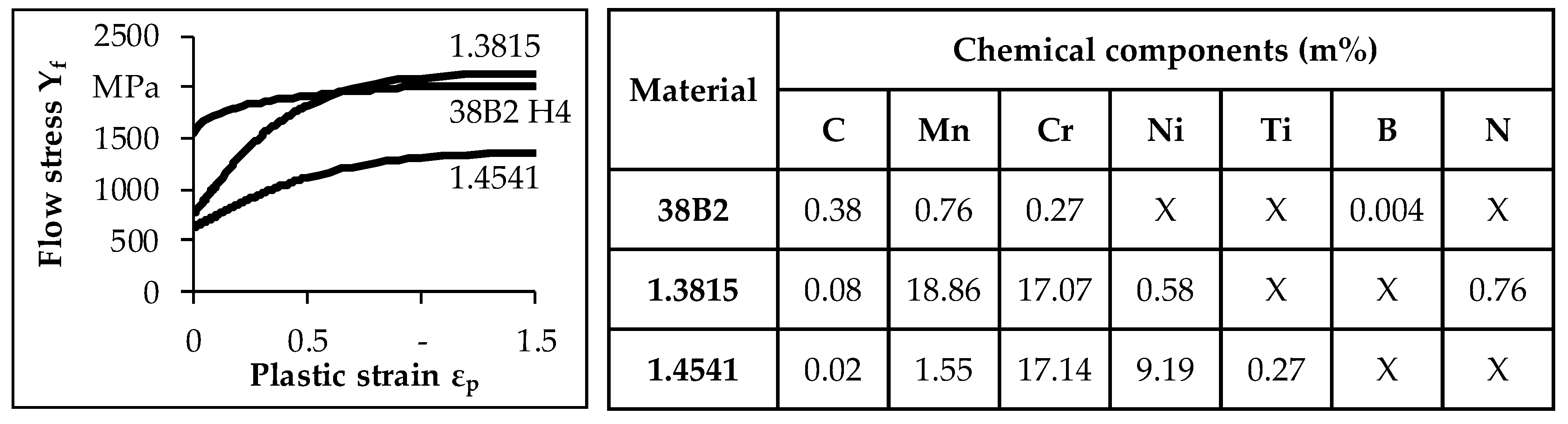
The approach presented in this paper relates to the shortening of the rivet manufacturing process chain by eliminating the need of the post treatment of the rivets in order to increase the process’s efficiency and the sustainability. The key aspect for this is the use of high strain hardening stainless steels as rivet materials. An overview of a selection of potential rivet materials is given in
Figure 3.
In the context of the material choice, high-nitrogen steels such as the featured steel, 1.3815, represent promising options. The chosen material, 1.3815, is an established high-nitrogen steel, which was already used for highly stressed retaining rings for turbo-generators due to its excellent material properties [
16]. Steels of this type are characterised by an exceptionally high nitrogen content and provide high strength, ductility and corrosion resistance [
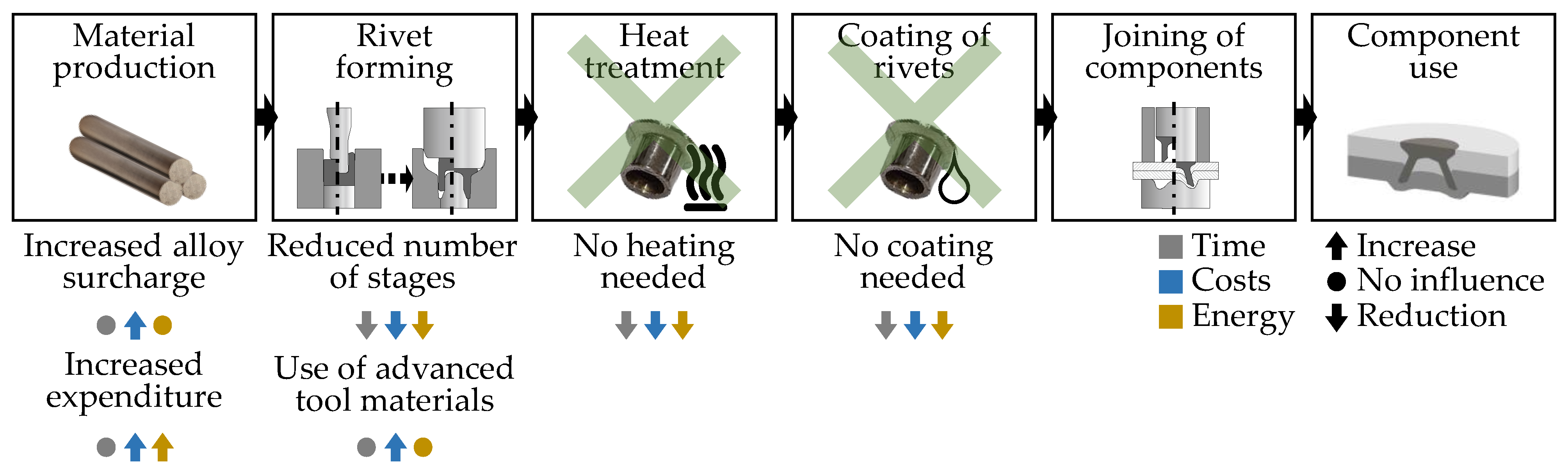
17]. Due to the high strain hardening, a sufficient rivet strength for joining can already be achieved through the forming process. Therefore, the usual heat treatment and coating of the rivets becomes obsolete, leading to cost, time and energy savings (see
Figure 4).
Thus, the benefits of forming as an efficient and sustainable technology are fully exploited. Furthermore, the comparison between the conventional and the new process in
Figure 2 also reveals that the new process consists of two forming stages in contrast to the usual number of up to six stages in the industry. Consequently, the energy and costs required for the manufacture of additional forming tools including the tool materials can be saved. However, these tools have to be more capable than before, so the required tool materials are more expensive than the commonly used ones. It must be pointed out that the production of materials such as high-nitrogen steels involves more expenditure compared to conventional steels, which is opposed to the cost and energy savings by omitting the heat treatment and the coating. There is a need for future research and development in relation to the material production processes in order to exploit the potential for energy and cost savings in this field as well. Nevertheless, the new approach contributes to an increase in the economic efficiency and sustainability of the rivet manufacture. As SPR is used in the automotive sector in particular, this is also an important step on the way to achieving fully sustainable mobility in the future, because the production history of each individual vehicle component counts in this case. A description of this approach is also presented by the authors in [
18].
3. Forming of Rivets with Graded Mechanical Properties
The new rivet manufacturing process, as presented by the authors in [
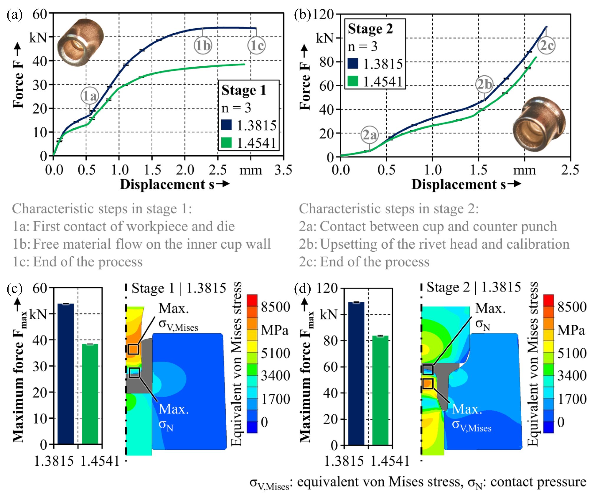
11], consists of two forming stages, involving cup-backward extrusion in stage 1 in combination with the forming of the rivet head and foot in stage 2. To obtain a deeper understanding of the process, the data concerning the forming force, F, and the punch displacement, s, can be correlated with the characteristic process steps (
Figure 5), which is carried out by means of a numerical process analysis with the aid of a numerical model that was validated in [
19]. Simufact Forming (simufact engineering GmbH, Hamburg, Germany) is used for the numerical investigations. The software allows for the transfer of the simulation results from the forming process to the simulation of the joining process. That enables the modelling of current material properties of the rivet over the whole process chain. All models are created in 2D. As described in [
9,
19], the considered rivet and sheet materials are characterised experimentally. Furthermore, model parameters like friction are either determined using an experimental test or identified inversely from experimental data.
In stage 1 (
Figure 5a), after the beginning of plastic deformation, the cylindrical workpiece comes into contact with the inner side of the die (1a). This results in a limited outward displacement of the material and increased friction. For this reason, the forming force suddenly rises. While the rivet shank is formed, the process force continues to rise, but the increase in force becomes lower due to the resulting gap between the cup and punch in the indented area of the punch (1b), which consequently leads to reduced friction until the end of stage 1 (1c).
In stage 2 (
Figure 5b), the first distinct increase in the force is attributed to the first contact between the cup bottom and the tip of the counter punch (2a). The beginning of the formation of the rivet head (2b) leads to a second considerable rise in the force until the rivet is finalised (2c). When the high-nitrogen steel, 1.3815, characterised by an extraordinary high strain hardening, is used as the rivet material, especially in stage 2, high maximum process forces of more than 110 kN are reached, which are associated with extremely high tool loads (
Figure 5d). According to the numerical analysis, an equivalent von Mises stress of more than 7000 MPa can occur in the forming tool at the end of the forming process in stage 2. The use of workpiece materials with increasingly higher strengths in combination with filigree component geometries entails growing demands on the forming tools in terms of stressability [
20]. Thus, knowledge of the occurring tool stresses is a crucial prerequisite for an adequate load-adapted tool design in order to prevent premature tool failure due to the formation of critical stresses during forming. The tool life of the forming tools can be increased by selecting suitable tool materials with sufficient strengths in addition to a design that is appropriate for the stresses involved [
21]. To meet the challenges associated with the forming of high-nitrogen steel and to enable the feasibility of the new rivet-forming process at all, a special tool concept including components made of tungsten carbide was elaborated and introduced by the authors in [
19]. As hard metals usually exhibit low tensile strengths, reinforcement systems used to form dies made out of tungsten carbide are required to avoid tensile stresses [
22], which is why the die used for the new rivet forming process is reinforced by a prestressing system consisting of three prestress rings. Thus, if conventional rivet materials are to be replaced by high strain hardening materials, comprehensive knowledge of the process is a mandatory prerequisite, and an appropriate tool concept is required in order to be able to master the process.
The mechanical properties of rivets, besides the rivet geometry, are decisive for the joining process and to achieve an adequate joint formation. This applies, in particular, to challenging joining tasks such as the joining of high-strength steels on the die side. The hardness analysis of the new rivets made of 1.3815 (
Figure 6a) reveals that over the whole rivet cross section, a mean hardness of about 600 HV 0.02 is reached. Thus, the hardness range of conventional rivets made of boron steel, which is 480 HV ± 30 HV in the heat-treated condition [
9], is not only completely covered, but is even extended by the new rivets that are manufactured without heat treatment.
4. Joining of High-Strength Steel and Aluminium Sheet
The use of a new rivet material provokes some issues for the joining process. One benefit of the corrosion resistance of the new rivet material is that the coating can be omitted. However, it is known from [
23,
24] that the surface conditions of the rivet and the sheets have influences on the friction between the rivet and the sheet materials during the joining process. Because of the changed friction properties, the rivet deformation and the generation of the interlock are affected.
In [
25], a study with a focus on the dependency of the friction between the rivet and the joining parts on the rivet’s surface condition was conducted. Hence, uncoated rivets and rivets coated with the very common coating, Almac
®, and with zinc–nickel with a topcoat were examined. To classify the friction properties of these surface conditions and to analyse the impact of different surface conditions on the characteristic joint parameters, modified pin-on-disc tests as well as experimental joining tests were conducted. It was found that the friction is reduced by the zinc–nickel coating, which is caused by the topcoat [
26]. This leads to an increased interlock and a reduced minimum die-side material thickness, as also shown by [
27]. However, it could be seen that the influence of the friction properties is limited and can be compensated by an adaption of the joining parameters. Furthermore, the friction properties of uncoated rivets and rivets plated with the common coating, Almac
®, are very similar. Thus, it can be stated that the changed surface condition does not impede the reliable joining.
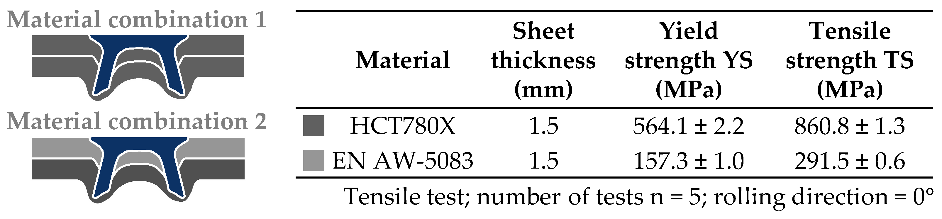
As described before, the new rivet is designed for the joining of material combinations consisting of high-strength steel and aluminium to cover a wide and relevant range of joining parts. The validation of the approach is conducted for the material combinations specified in
Figure 7. For the comparison to a conventional rivet, the rivet type from [
9] is used. This rivet has a geometry that fulfils the requirements of both material combinations. It is made of boron steel 38B2 and quenched and tempered to a hardness level of 480 ± 30 HV. The surface is coated with Almac
®.
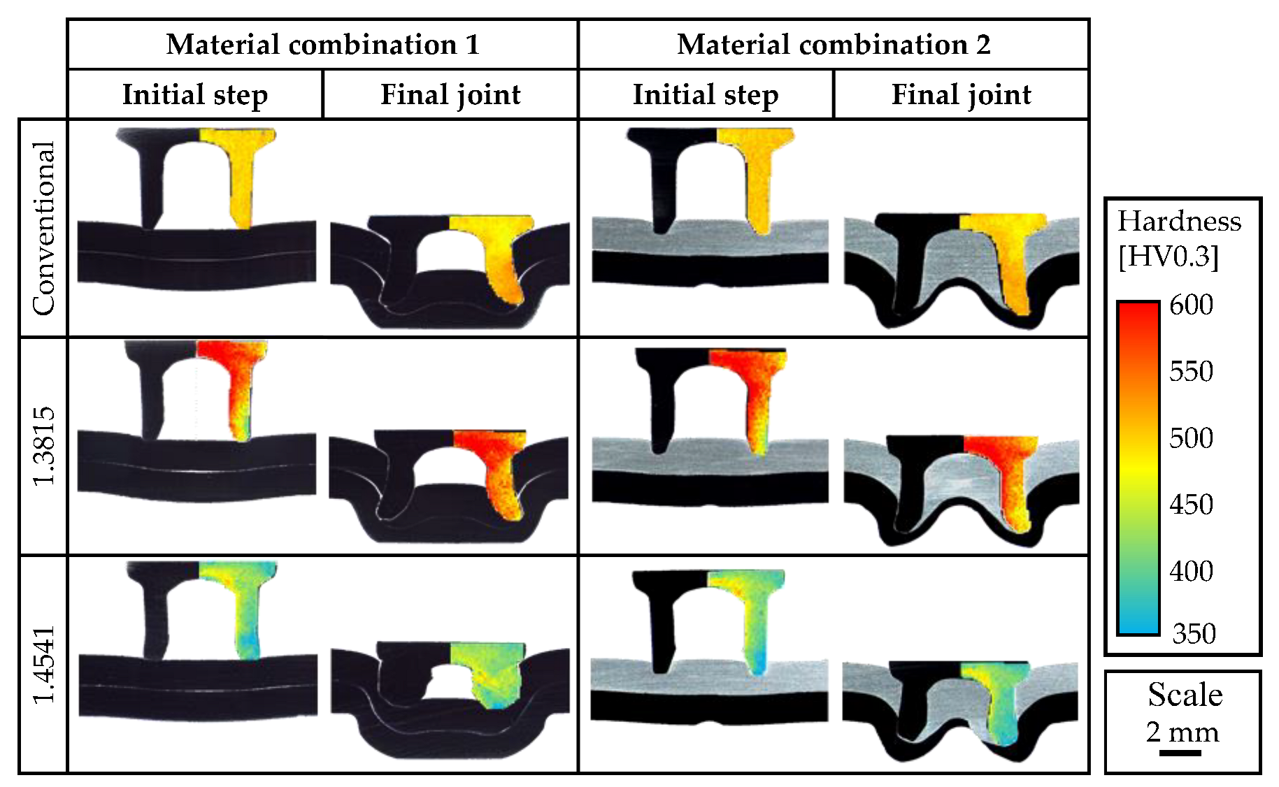
A comparison between conventional rivets and the new type of rivet made of 1.3815 and 1.4541 is initially made by evaluating the rivet deformation and the joining results. In the cross section of the joints, the deformation of the rivets can be analysed (
Figure 8).
Due to the geometrical deviations of the rivets made of 1.3815 and 1.4541 compared to the target geometry that are caused by the forming process, the rivet head diameter is much smaller than that with conventional rivets. Instead of the considered head diameter of 7.75 mm, a diameter of approx. 7 mm is achieved. This deviation mainly results from a reduction in the forming stroke, which is required to avoid the fracture of the forming tools. As described before, the forming force rises very strongly during the forming process due to the high strain hardening of the new rivet material, 1.3815. Further deviations exist within the rivet foot and the shank area. These deviations are caused by a sporadic tilting of the counter punch, especially during the first forming step. However, the geometrical deviations do not impede the joining process. Instead, it can be demonstrated that the joining result with rivets made of 1.3815 fulfils the common quality criteria of [
2]. In addition to the examination of the geometrical deformation of the rivets, the hardness within the rivets is measured so that the change in the material condition can be analysed, too. As the material condition is almost homogenous within the conventional rivet, due to the heat treatment, the material hardness within the new rivet type is locally different. In the initial joining step, the initial hardness distribution is still existent. Compared to the conventional rivet, the hardness within the outer rivet foot is lower than with the rivet made of 1.3815. Nevertheless, as the hardness within the conventional rivet increases by approx. 15% during the joining process, the increase in the hardness within the rivet foot of the rivet made of 1.3815 is much higher, and at the end of the process, a comparable hardness is reached. The hardness distribution within the rivet made of 1.4541 is similar to the hardness distribution within the rivet made of 1.3815, but the hardness level is much lower. The lower material strength of 1.4541 causes the compression of the rivet, and no joint can be created. Therefore, it can be seen that the rivet material strength has a significant influence on the deformation behaviour of the rivets and the joining result.
The measured characteristic joint parameters for the joining with conventional rivets and rivets made of high-nitrogen 1.3815 steel are shown in
Table 1. The method of measuring the interlock, u, and the minimum die-side material thickness, t
r, in the cross section was explained above. Due to the excessive deformation of rivets made of 1.4541 and the failed joint generation, no joint parameters can be measured in this case. As the comparison of the measured interlock and minimum die-side material thickness reveals, a very competitive joining result can be achieved with high-nitrogen steel rivets. The required values are surpassed with both material combinations. Moreover, the achieved joint parameters can be improved with material combination 2 compared to the use of the conventional rivet. This is due to the tailored strength distribution within the elaborated rivet made of high-nitrogen steel. During the design of this rivet, a study regarding the influence of the local material strength within the rivet was conducted (see [
28]). In this context, it could be shown that a reduced material strength within the outer rivet foot leads to an increased interlock with material combination 2. However, it can also be seen that the scattering of the measured values is increased when using this rivet. This is caused by the explained geometrical deviations, especially in the areas of the rivet shank and the rivet foot.
As the competitive joining of the two material combinations with rivets made of high-nitrogen 1.3815 steel could be proven using the illustrated joining tests, the joint strength has to be determined, too. Therefore, in [
29], the strengths of joints riveted with conventional rivets and rivets made of 1.3815 were analysed using experimental tests according to the standard in [
30]. Tests under quasistatic load were conducted by using the LWF-KS2-specimen and a Zwick Z 1484 testing machine (ZwickRoell GmbH & Co. KG, Ulm, Germany). The joints were tested under tensile load and shear load. The force was measured using the testing machine. The strain was measured locally at the specimen by using GOM ARAMIS (Carl Zeiss GOM Metrology GmbH, Braunschweig, Germany). The kind of failure of the joint, which is classified in [
31,
32], was also documented. The achieved maximum force until the failure of the joint and the kind of failure in accordance with the used rivet are shown in
Table 2.
The joint strength with material combination 2 is lower than that with material combination 1, and the reached force under tensile load is lower than that under shear load for both material combinations. These effects are typical for SPR [
33]. The lower joint strength with material combination 2 is caused by the lower material strength of the punch-sided aluminium. For a deeper understanding of these observations, the failure modes can be examined. They are shown in
Table 2. The failure modes under tensile load with the two material combinations are different. In the case of material combination 1, the rivet foot is torn from the die-sided sheet. Because of that, the interlock of the joint is crucial for the reached joint strength. With material combination 2, the rivet head is torn from the punch-sided sheet. In this case, the material strength of the punch-sided sheet is decisive for the joint strength. Under shear load, the joints with conventional rivets fail for both material combinations through the tearing of the rivet foot from the die-sided sheet. With rivets made of high-nitrogen steel, the joint fails for material combination 2 through a combination of the previously explained failure modes. This is caused by the lower rivet head diameter. The geometrical deviations in the area of the rivet head are the reason for the lower joint strength reached with the high-nitrogen steel rivets for material combination 2. As the tearing of the rivet head from the punch-sided sheet is the main failure mode with joints of material combination 2, the joint strength directly depends on the rivet head’s diameter. Thus, the smaller rivet head diameter of the rivets made of 1.3815 provokes a lower joint strength of approx. 25%. For material combination 1, instead, a comprehensive strength can be achieved with rivets made of 1.3815 compared to the conventional rivet, because the tearing of the rivet foot is the main failure mode. Because of the lower joint strength with the rivets made of high-nitrogen steel for material combination 2, the elimination of the geometrical deviations of the new rivets has to be a goal of further research. Nevertheless, the achieved joint strength with rivets made of 1.3815 is on the same level as that measured in [
34] for similar material combinations.
5. Summary and Outlook
As an approach for sustainable manufacturing, the potential of a novel rivet manufacturing process to save costs, time and energy is pointed out. The usually necessary treatment of the rivets after they are formed, including hardening and tempering, as well as coating, can be omitted due to the use of high strain hardening stainless steel as the rivet material. Thus, the entire process chain is shortened. Additionally, the new approach makes it possible to produce rivets with graded mechanical properties. This is a special feature compared to conventional rivets, which provide homogeneous properties due to the heat treatment. This opens up the opportunity of producing customised rivets with a varying local hardness. However, the change in the rivet material and processing causes some issues along the process chain. In this paper, a holistic evaluation of the challenges within the forming of high strain hardening steel and the impact of the changed rivet properties on the joining result is given. The high strain hardening of the used high-nitrogen steel causes a very high tool load. Thus, geometrical deviations result from the current forming process. Even though material combinations of high-strength steel and aluminium alloys can be successfully joined with the new rivets, it must be stated that the geometrical deviations of the rivets must be reduced in order to ensure an adequate joint strength. Therefore, future work will focus on the further development of the tool concept and on improved forming strategies to extend the existing process limits due to the high tool loads. Further research regarding tailored mechanical rivet properties will be conducted as well to improve the performance of the riveted joints. In the future, the approach can be transferred to various fastener production processes to reduce energy consumption, costs and time. This contributes to a reduction in emissions and to the protection of natural resources, which are important factors for the increase in economic efficiency, ensuring the competitiveness of manufacturers.


