Article

Method for Defining Parameters of Electromechanical System Model as Part of Digital Twin of Rolling Mill

by
Vadim R. Gasiyarov
1,
Andrey A. Radionov
1,*,
Boris M. Loginov
2,
Mark A. Zinchenko
2,
Olga A. Gasiyarova
3,
Alexander S. Karandaev
4 and
Vadim R. Khramshin
4
1
Department of Automation and Control, Moscow Polytechnic University, 38, Bolshaya Semyonovskaya Str., 107023 Moscow, Russia
2
Central Electrotechnical Laboratory, PJSC Magnitogorsk Iron and Steel Works, 455000 Magnitogorsk, Russia
3
Department of Material Science, LLC NPP Uchtekh-Profi, 147, Kommuny Str., 454080 Chelyabinsk, Russia
4
Power Engineering and Automated Systems Institute, Nosov Magnitogorsk State Technical University, 38, Lenin Avenue, 455000 Magnitogorsk, Russia
*
Author to whom correspondence should be addressed.
J. Manuf. Mater. Process. 2023, 7(5), 183; https://doi.org/10.3390/jmmp7050183
Submission received: 6 September 2023 / Revised: 10 October 2023 / Accepted: 11 October 2023 / Published: 12 October 2023

Abstract

:
Creating digital twins of industrial equipment requires the development of adequate virtual models, and the calculation of their parameters is a complex scientific and practical problem. To configure and digitally commission automated drives, two-mass electromechanical system models are used. A promising area in which to implement such models is the development of digital shadows, namely drive position observers. Connecting virtual models for online data exchange predetermines the tightening of requirements for their parameter calculation accuracy. Therefore, developing accessible techniques for calculating electromechanical system coordinates is an urgent problem. These parameters are most accurately defined by experiments. The contribution of this paper is the proposition of a method for defining the two-mass system model parameters using the oscillograms obtained in the operating and emergency modes. The method is developed for the horizontal stand drives of a plate mill 5000 and is supported by numerical examples. The technique is universal and comprises calculating the rotating mass inertia torques, elastic stiffness and oscillation damping coefficients, and the time constants of the motor air gap torque control loop. The obtained results have been applied to the development of the elastic torque observer of the rolling stand’s electromechanical system. A satisfactory coordinate recovery accuracy has been approved for both open and closed angular gaps in mechanical joints. Recommendations are given for the use of the method in developing process parameter control algorithms based on automated drive position observers. This contributes to the development of the theory and practice of building digital control systems and the implementation of the Industry 4.0 concept in industrial companies.

1. Introduction

According to the authors of [1], the current trend in commercial production and monitoring is the digital twin (DT), which is being studied and has shown promising results in facilitating the implementation of the Industry 4.0 concept. The basic idea of using DTs in production is the dynamic digital software interpretation of physical assets and processes [2]. In this context, a digital twin refers to a digital copy of a machine (or its component, e.g., an electromechanical system) or a production line in the course of its development or state change. Therefore, they are defined as follows: “Digital twins are copies of physical production assets which facilitate their monitoring and control” [3]. The application of DTs in production and transport is considered in papers [4,5,6,7,8].
In the metallurgical industry, the objects of DT implementation are the process lines of rolling mills. The created DTs should be used at all life cycle stages (except for disposal), including design, development, virtual commissioning (VC), and asset condition monitoring [9,10]. Therefore, digital twin prototypes (DTPs), instances (DTIs), and aggregates (DTAs) combining DTPs and DTIs into a single complex should be created [11]. Separate areas are developing digital shadows (position observers) of rolling stand electromechanical systems and building control systems on their basis [12,13].

1.1. Simulation Models for DTs

As a rule, digital twins are considered in conjunction with simulation models, which are virtual analogues of physical assets [14]. Ref. [5] points to the fact that DTs develop modeling and simulation technologies. In [15], an important conclusion was drawn; it was stated that “computational models used to define the current state of a physical object are the same models that can be used in modeling to predict future states”. This statement is applied in this article for the study of the elastic torque observer on the spindle shaft of the rolling stand.
The problems related to the development and application of digital models for the creation of DTs of industrial systems are considered in [16,17,18,19]. Refs. [20,21] note that in recent years, electrical machines powered by a frequency converter have been widely used as torque sources in control systems. Such devices contain complex mechanical transmissions, which may not always be considered rigid. “The operation of such industrial equipment as rolling mills is based on elastic couplings, and a two-mass model of the system is conventionally used for their analysis” [22]. At the same time, “light shafts are used in powerful systems with the significant inertia torques of the electric machine and load. In such conditions, the device model can no longer be considered as a system with a rigid shaft”. Paper [23] considers the dynamics of electromechanical systems with long shafts and elastic couplings. The factors influencing their dynamic behavior, particularly the amplitude of torque oscillations and velocities in a mechanical system, are distinguished. These factors include:
-
“parameters of the transmission shaft, i.e., its length and diameter, as well as the inertia torques of the masses attached”;
-
“a strategy for controlling an electric motor, while taking into account that the development of this strategy cannot be limited by the dynamics of an electric motor and the synthesis of its control only, excluding other system components”.
In general, [23] confirms the relevance of the selected scientific area in the study of two-mass systems with an elastic shaft. The objectives considered in the paper are prototypes of the developments described in this article.

1.2. Multi-Mass Models of Electromechanical Systems in Rolling Mills

A necessary condition for creating and implementing DTs at the aforementioned life cycle stages is the availability of a virtual model describing the object’s properties in operating modes. The electromechanical systems of rolling stands are characterized by the acceleration (with or without metal in the rolls), braking, and load change (shock or smooth) modes determined by the process. In this regard, the most important problem in creating DTs is developing models that reliably describe the object’s behavior in dynamic modes. Scientific papers [24,25,26] consider developing dynamic models of the electromechanical and mechatronic systems of rolling mills. Ref. [27] emphasizes that when creating DTs, a compromise should be found between the complexity of the mathematical description of variable frequency drives based on Park–Gorev equations and the capabilities of simpler models reliably describing the process, the consideration of which is relevant for solving a specific problem.
When using DTs for the development and VC of drive control systems, in many cases, there is no need to simulate the transients of the “internal” coordinates of motors (current, voltage, magnetic flux). Therefore, it is advisable that simplified simulation models considering the coordinates that are “external” to the motor are used. These models should reliably describe the elastic properties of the kinematic transmission, the impact of non-linearities (gaps in mechanical joints), the shaft torques, and other non-electrical parameters. To study the electromechanical systems of rolling stands, two-mass (rarely three-mass) models are used [28,29]. In this case, the first and the second masses are, respectively, the motor’s rotor and the roll, which have comparable inertia torques. The masses are generally kinematically linked using a complex-design shaft (spindle) of a bar (slipper) type [30]. It is characterized by elastic properties, manifested during shock load changes, and gaps in the joint mechanisms. Such a two-mass system is adopted for consideration herein. The subject of study is the model parameters to be determined via the experiment.
Ref. [31] emphasized that limiting the dynamic torque is an acute problem for plate and wide-strip hot mill drives. This is because the electromechanical systems of such units operate with a shock load at the moment of workpiece biting (hereinafter, the term “workpiece” refers to a semifinished product between the initial billet–slab and the final product–sheet).

1.3. Problem Relevance

The literature overview shows that the “conventional” two-mass model application areas are the study and optimization of process modes [32,33], the synthesis and adaptation of drive controllers [34,35,36], and the limitation of dynamic loads [37,38]. Due to the recent development of digital technologies, two-mass models are actively used in the following:
  • digital twins;
  • the development of digital shadows;
  • the development of smart control algorithms.
In [39], a two-mass system model is applied to develop drive position observers, which is a promising field. The use of state observers for studying and improving the dynamic performance of two-mass systems is considered in [40,41,42]. In [43], oscillation and disturbance damping in the system of a two-mass main drive of a rolling mill is studied. The problem is solved using a pole position controller with an improved state feedback and the Kalman filter. Ref. [44] provides a scheme for controlling the speed of rolling mill drives. For the main control loop, a speed controller is proposed; it uses an observer-based state feedback compensator. Ref. [45] proposes a new approach to optimizing observers in a two-mass system and the corresponding choice of a mathematical model; three observers are described for a two-mass electric drive with a flexible shaft.
Theoretically, the analysis and experimental studies of the presented developments show their advantages compared to the conventional PI controller. At the same time, the main disadvantage of the systems with electric drive state observers is the complexity of their practical use. These developments have been tested on special laboratory benches, so no information is given on their industrial adoption. In this regard, the problem of developing relatively simple observers of electric drive coordinates is being solved, which, unlike state observers, do not require a complex mathematical apparatus and control algorithms. Control systems based on them shall be implemented in the software of the logic controllers used in rolling mills.

1.4. Methods for Calculating the Parameters of Two-Mass System Models

Papers [46,47,48] consider the problem of determining the parameters of two-mass models. Ref. [49] highlights that the problem is complicated by the fact that, in many electrical systems, the characteristics of torque transmission on the shaft are nonlinear, and the object parameters are unknown. To solve this problem, an adaptive controller has been developed, and the adequacy of the results obtained has been proven. In [50], a review of the methods used to estimate the parameters of two-mass mechanical systems in electric drives is conducted. An indirect closed-loop method for identifying the parameters of a two-mass system is proposed and compared with other known methods. Based on the validation results, a conclusion is made on their applicability for estimating the parameters of two-mass mechanical systems. Ref. [51] considers an online indirect parameter identification method that simultaneously estimates six parameters using least squares with an adaptive filter. Its disadvantage is the high computational load that limits its use in real-time identification.
All methods considered are analytical. They conduct the identification of model parameters using computational operations of varying complexity. When making calculations, tabular (nominal) or average data are used, which always differ from the actual parameters of the object. Such a difference can be commensurate with the identification error, which should not exceed 5–10% for electromechanical systems. Thus, the use of the considered methods does not provide the high accuracy required for developing digital twins. Thus, it is necessary to develop a method based on the results of experiments conducted on the object under study. As a result, the actual parameters are “automatically” taken into account, increasing the accuracy of the twin creation (the reproduction of virtual space) of the equipment and processes. The advantage of using this approach is also the ability to conduct experiments at any frequency. This makes it possible to correct the model parameters considering their changes caused by the object’s physical wear and tear.
The authors of [52] rightfully argue that “many researchers implemented the idea of using the observers based on dynamics instead of sensors”. Examples of such observers are considered in the author’s publications [27,53]. Ref. [27] describes a digital observer of the elastic torque on the rolling stand spindle; on its basis, an elastic torque closed control system has been developed. Its technical efficiency has been proven via mathematical models and experiments. However, the study found that the most important factor affecting the reliability of the elastic torque calculation (recovery) in dynamic modes is the electromechanical system model parameter definition accuracy. Obviously, such parameters can be defined most accurately via experiments.
Confirming this conclusion, ref. [54], on the basis of bench tests, substantiates a method for defining the parameters of a multi-mass system with elastic coupling, gaps, and oscillation damping. According to this technique, the motor inertia torque, the motor torque, and the response time of this torque are recognized and corrected. Also, the calculation of the torque response time and the electromechanical time constant of the motor are stipulated for. This paper emphasizes the relevance of the practice-oriented definition of model parameters. Herewith, the literature describes no techniques for calculating the two-mass system parameters using experimental data. This publication aims to fill this gap. The method is developed using the example of the two-mass electromechanical system of the mill stand 5000 described below.
The article content is arranged in the following sequence. Section 2 describes the research object: the electromechanical system of the 5000 mill stand. It also formulates the research objectives. Section 3 presents a method for calculating the parameters of a virtual model of an electromechanical system from the oscillograms of dynamic modes. It gives examples of calculating the model parameters. Section 4 considers the transient processes of the elastic spindle torque, obtained with the help of an observer, and the adequacy of the restored and experimental data is confirmed. Section 5 studies the roll capture under various initial conditions; recommendations regarding the application of the methodology provided in the development of DTs of electromechanical systems are substantiated. Section 6 provides the conclusions drawn regarding the article content and outlines future prospects for research.

2. Problem Formulation

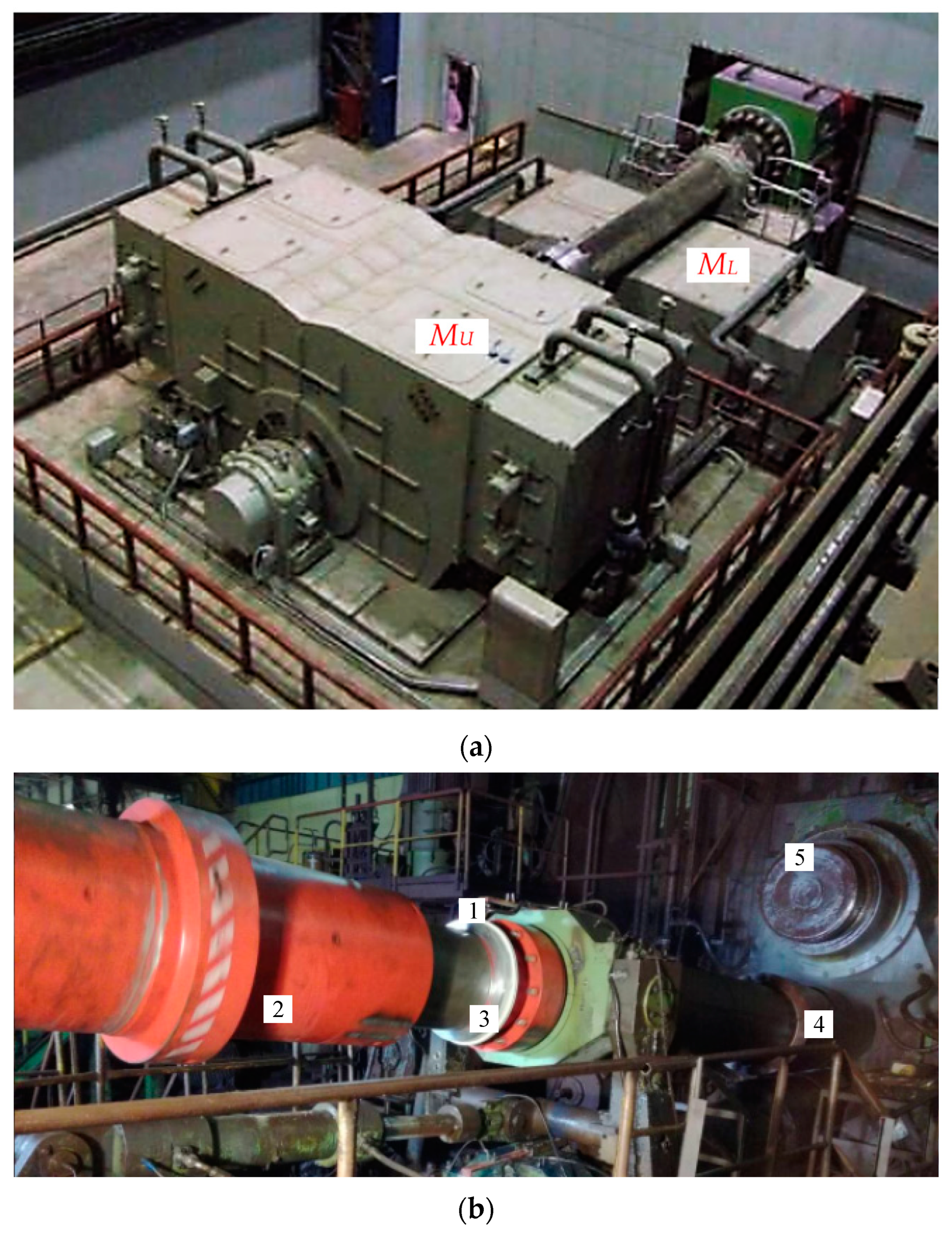
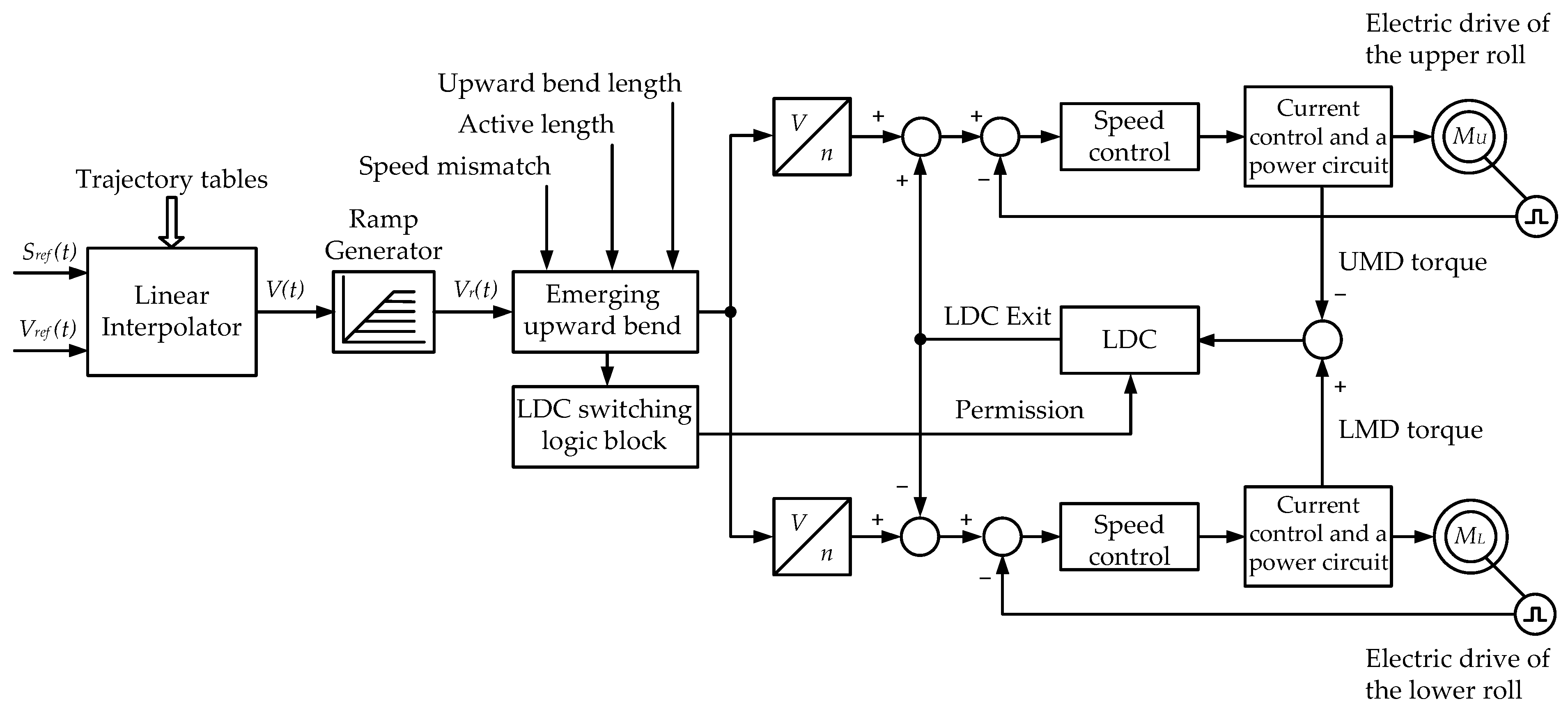
2.1. The Mill 5000 Stand Drive Characteristics

The main drives of the upper and lower rolls (UMD and LMD) of the rolling mill under study are arranged individually based on synchronous motors (Figure 1a) with rpm control. Figure 1b shows a photo of spindle 2 connected to upper work roll 4 [27]. Motor rotors are the first “masses” of two-mass electromechanical systems, and the reduced inertia of the work 4 and support 5 rolls is the second “mass”. As shown below, both masses are comparable in magnitude while there are no devices with a similar inertia in the gears. Therefore, it is fair to assume that the main roll drive lines (main lines) are two-mass electromechanical systems with elastic constraints and angular gaps in the spindle joints. This assumption is valid for most stands of plate and wide-strip hot mills [31,55].
Figure 2 shows the diagram of the system for setting and controlling the UMD and LMD speeds. Synchronous motors MU and ML are powered by frequency converters; the speed change trajectory is formed by the APCS model according to the criteria of mill performance and by obtaining the specified temperature regime of rolling. The drives are described in more detail in [56].
Figure 3a shows the kinematic diagram of the two-mass system “motor rotor-roll” [27]. Figure 3b shows a simplified diagram of the model of the closed two-loop automated control system (ACS) of the drive speed. In the diagram, blocks 3, 5–7 are typical blocks of a two-mass system model: block 5 simulates gaps in mechanical transmissions, and block 7 defines the natural attenuation of transient oscillations in the mechanical part. Block 2 simulates a multidimensional torque control loop; its transfer function is discussed below in Section 3.
On the diagram, Tµ is the uncompensated time constant; J1 and J2 are the inertia torques of the 1st and 2nd masses; C12 is the mechanical transmission elasticity coefficient; β is the coefficient responsible for natural damping (such as viscous friction); Mref is the measured motor torque; MM is the electromagnetic torque of the motor; M12 is the spindle elastic torque; ω1 and ω2 are the motor and roll speeds; kFS is the first mass speed feedback gain; and kFM is the motor torque feedback gain in the figure.
The simulated object parameters are provided in Table 1. They are defined by the motor and roll manufacturers and are thus approximate. Under real conditions, the inertia torques are affected by the variable mass of the rolled metal, the inertial properties of the spindle, the thrust bearings, and other mechanical transmission elements. These parameters for the upper and lower rolls differ and cannot be accurately specified when developing the model. Herewith, the reduced mass inertia torques can be defined via experiments with the object, which will provide a high model parameter calculation accuracy. Table 1 also does not contain the magnitude of the angular gap in the spindle joint, which cannot be calculated theoretically but can be defined experimentally. The method and example of measuring the angular gap in the spindle joints of the mill 5000 stand are given in [55] and are not considered herein.

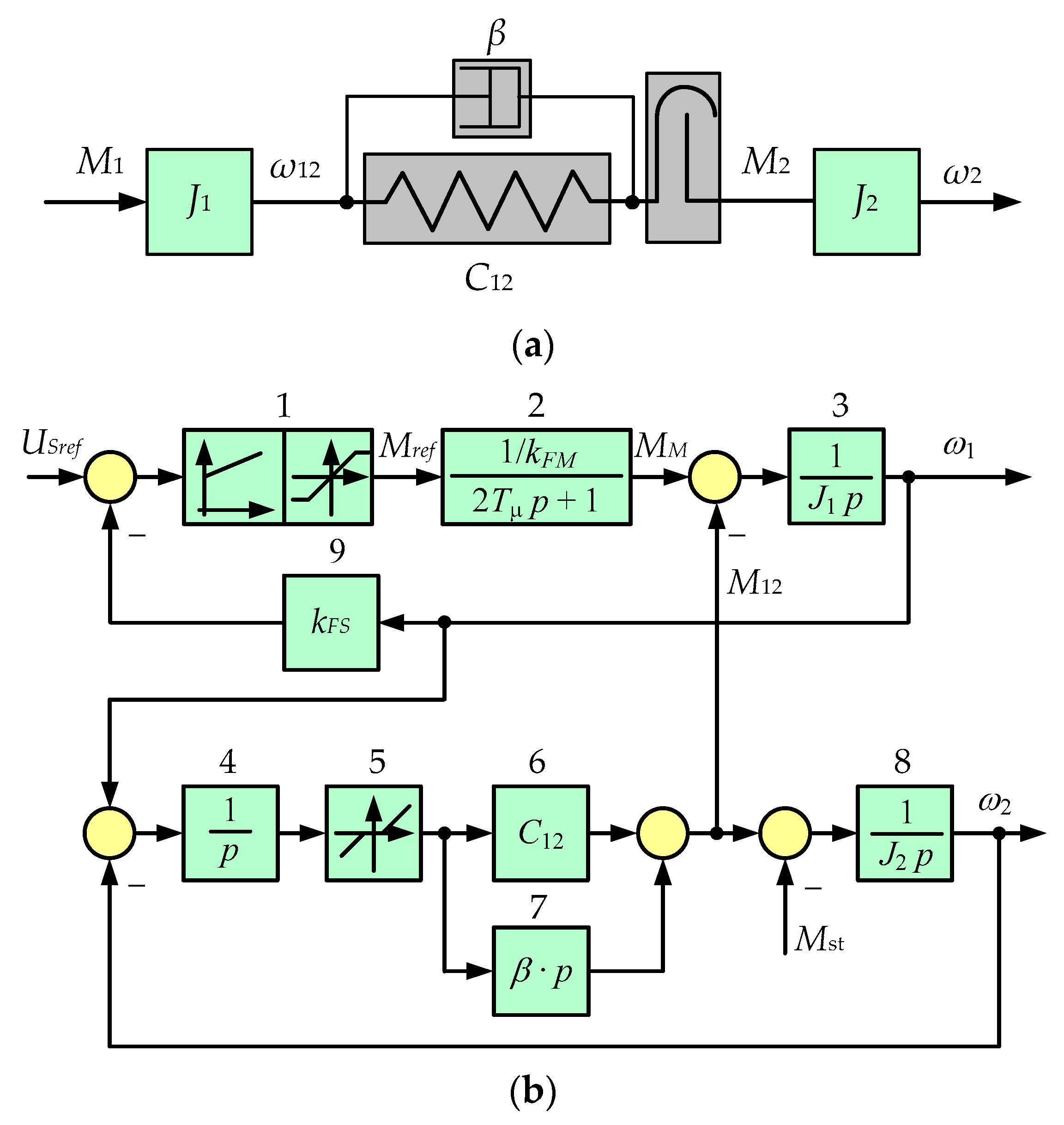
2.2. Two-Mass System Position Observer Characteristic

When developing an observer, non-linear block 5, simulating gaps, and blocks 1 and 9, which implement the speed control loop, are excluded from the diagram shown in Figure 3b. The resulting diagram is shown in Figure 4a and corresponds to the matrix structure shown in Figure 4b [27].
The matrix structure (Figure 4b) corresponds to the system of differential equations in the state space:
d M 1 d t = 1 T m M 1 + 1 T m K o M M 1 r e f , d ω 1 d t = 1 J 1 M 1 1 J 1 M 12 , d M 12 d t = C 12 ω 1 C 12 ω 2 + β J 1 M 1 β J 1 + J 2 J 1 J 2 M 12 + β J 2 M c , d ω 2 d t = 1 J 2 M 12 1 J 2 M c .
where M1ref is the motor torque reference and Tm is the electromechanical time constant.
Based on the above equations, an observer of the elastic torque and the 2nd mass speed has been developed (Figure 5), the detailed information of which is given in [27]. Since the observer is built based upon a model of a two-mass electromechanical system, the accuracy of the online parameter recovery depends on the accuracy of the model coordinate calculation.

2.3. Research Objectives

It is difficult to reliably determine the multi-mass system model parameters since some of them cannot be measured directly. These include the reduced inertia torques, which are coefficients characterizing the elastic properties of mechanical transmissions, etc. This requires the development of algorithms for calculating these parameters using the observed coordinates. The developed method should stipulate for the definition of all the model parameters shown in Figure 3b (and, accordingly, Figure 5); its basic aspects are as follows:
  • calculating inertia torques J1, J2;
  • defining the elastic stiffness coefficient C12;
  • defining the oscillation damping coefficient β;
  • defining the time constants of the transfer function of the torque control loop.
The techniques and examples used to calculate these parameters are discussed below. The calculations are based on the results of processing the oscillograms obtained on the mill 5000 in the operating and emergency modes.

3. Materials and Methods

3.1. Calculating Inertia Torques

To define the inertia torques, the drive constant acceleration experiment was performed. In the example below, they are defined by the acceleration oscillograms in the reverse mode (Figure 6); thus, the speeds and torques are in the negative region. The dependencies of the set and actual speeds in window 3 coincide; therefore, only the set ones are denoted.
The motor torques MM(U) and MM(L) are measured by the sensors as part of frequency converters. The spindle elastic torques MS(U) and MS(L) are measured by the overload monitoring system installed on the mill [57]. Figure 1b above shows the mounting of the elastic torque sensor 1 on telemetric ring 2 fixed on upper roll spindle 3. A similar sensor is installed on the lower roll spindle. The measured torque signals are amplified and transmitted to the data processing and visualization system. They are diagnostic and are not included in the drive control algorithms.
The total two-mass system inertia torque is defined by the dynamic torque MDYN with the basic drive equation:
J Σ = M DYN d ω d t .
Acceleration is facilitated by the motor air gap torque (MM(U) or MM(L)). In the constant acceleration mode (Figure 6), this torque is constant and depends on the inertia torques of both masses J = J1 + J2., e.g., for the upper roll main line, J∑(U) is defined by the steady-state value of the MM(U) torque:
J Σ ( U ) = M M ( U ) d ω d t = 260,000 1.445 = 179,930   kg m 2 .
At constant acceleration, the spindle torque (MS(U) or MS(L)) depends only on the second mass (roll) inertia torque J2. This is explained by the fact that, in this case, the torque transmitted to the second mass is equal to the spindle’s twisted shaft elastic torque and does not depend on the first mass inertia J1. This allows the second mass inertia torque to be defined for, e.g., the upper roll:
J 2 ( U ) = M S ( U ) d ω d t = 80,000 1.445 = 55,363   kg m 2 .
The first mass (rotor) inertia torque is equal to the difference between the J and J2 values; therefore, for the upper roll engine, J1(U) = 124,567 kg∙m2.
The dynamic torques defined by the oscillograms (Figure 6) are given in Table 2. It also provides the inertia torque calculation results. The 1st mass inertia torques calculated using the oscillograms differ slightly from the datasheet rate of the motor rotor inertia torque at 125,000 kg∙m2, as specified in Table 1. This confirms the reliability of their experimental definition. The greater magnitude of the 2nd mass inertia torque of the upper roll electromechanical system is explained by the longer upper spindle compared to the lower one. This is confirmed by Figure 1a, where the lower roll motor spindle ML is virtually invisible while the motor spindle MU is several meters long.
The elastic stiffness is defined by the drive emergency shutdown oscillograms. Figure 7a shows the transient speed when the workpiece is stuck in the rolls. In this case, the 2nd mass is fixed, and the 1st mass experiences torsional oscillations due to spindle elasticity. It is known that the torsion pendulum oscillation period is defined by the equation [58] T = 2 π J / C 12 , from which, with a known 1st mass inertia torque, the spindle stiffness is determined: C 12 = 4 π 2 J T 2 . Considering the oscillation period equal to 0.254 s (see Figure 7a), the stiffness is C12 = 76,489,587 N∙m/rad.

3.2. Defining the Oscillation Damping Coefficient

In a real two-mass system, dissipative forces occur, and their impact on damping is considered by the coefficient β in block 7 (Figure 3b). In the pendulum diagram in Figure 8, this block is shown as an amplifier with B factor.
Using this diagram, the calculated damped speed oscillogram is obtained, as shown in Figure 7b. It shows that the oscillation amplitude decreases by a factor of 2 for approximately 8 speed oscillation periods. The damping coefficient is defined by the logarithmic damping decrement Θ [58]:
δ T = Θ = ln A ( t 1 ) A ( t 1 + T ) ,
where A ( t 1 ) and A ( t 1 + T ) are the amplitudes of two successive oscillations, and δ is the attenuation coefficient.
The T value is called the conditional damped oscillation period. Introducing the denotation 2 δ = β J 1 , we obtain the following:
β = 2 J 1 Θ T .
By substituting the inertia torque J1 and the parameters T and Θ, defined by the oscillogram in Figure 7a, into Equations (3) and (4), we find that the β value is within 90,000–600,000 N∙m∙s/rad. Substituting the same parameters into the model, as shown in Figure 8, we find that the coefficient β ≈ 100,000 N∙m∙s/rad provides the most accurate coincidence of the curves in Figure 7a,b. In this case, the calculated oscillation period corresponds to the period on the real oscillogram, which confirms the reliability of the model parameter definition.
Indeed, the recommendation to use the emergency mode oscillograms to define the model parameters is not correct. The drive shutdown mode in the presence of metal in the rolls cannot be specially arranged. In the case described, the oscillograms were recorded using a permanent PDA (Process Data Acquisition) system installed on a mill 5000. Currently, such systems operate in all rolling mills, and unfortunately, emergency modes caused by strip sticking are not uncommon. Therefore, the required oscillograms can be one-time obtained by means of a “passive experiment”.

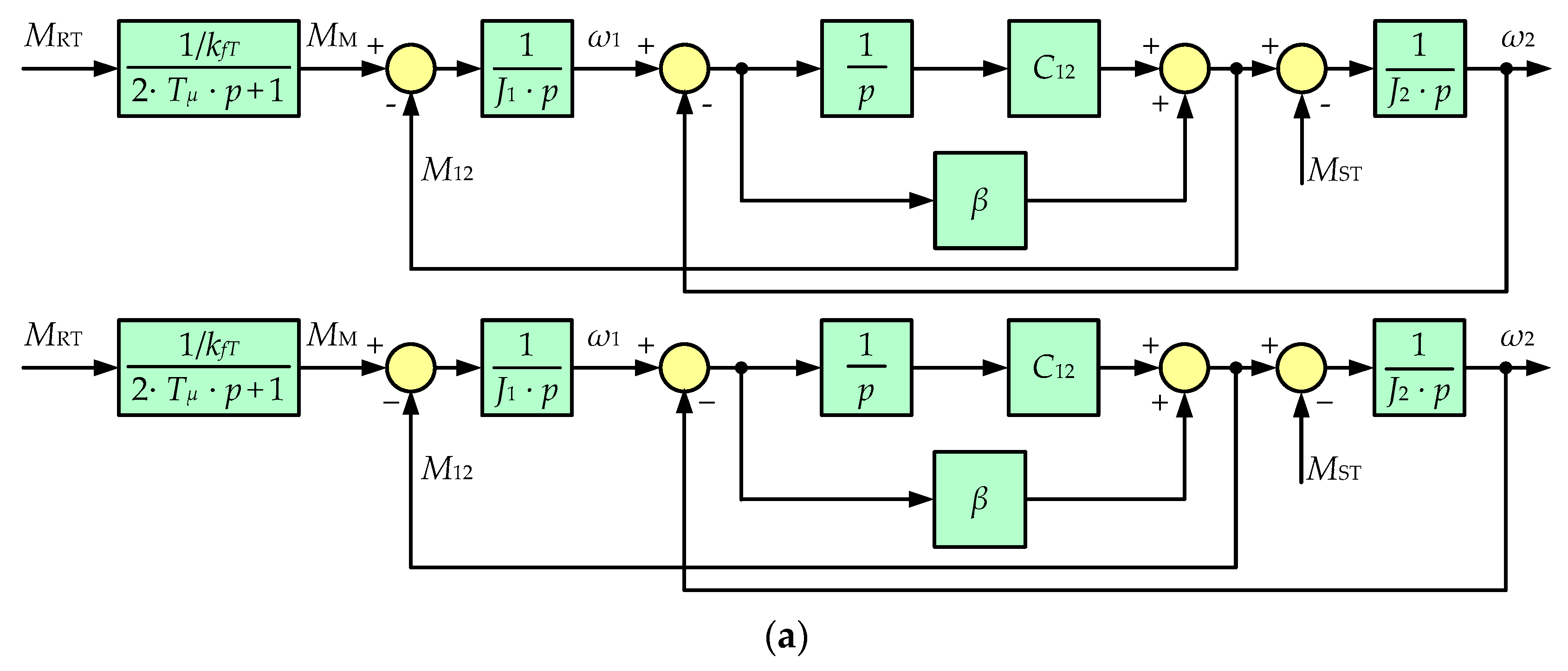
3.3. Transfer Function of the Torque Control Loop
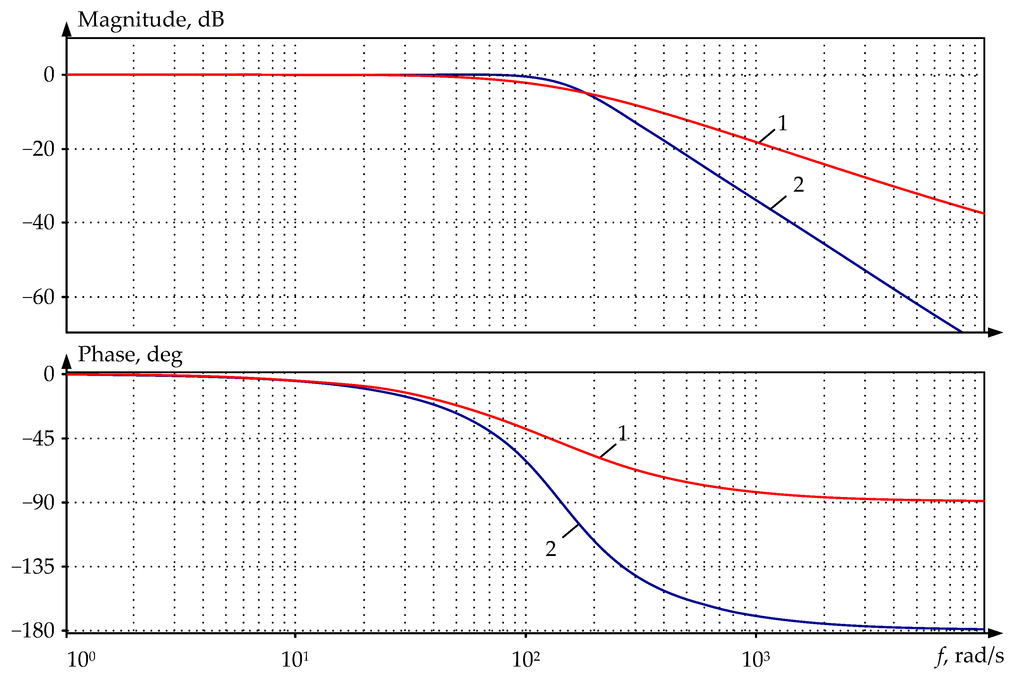
Oscillogram in Figure 7a shows that when the drive is turned off, the speed transients have the nature of slowly damped oscillations. Therefore, it is advisable that a closed torque control loop (block 2 in Figure 3b) is expressed as a link with a transfer function:
W 3 M ( p ) = 1 T 1 2 p 2 + 2 T 1 ξ p + 1 .
This loop can be simulated by first- or second-order links (filters), while defining the time constant T1 is an important problem. This time constant should be defined by the lag of the actual motor torque curve relative to the torque reference when adjusting the speed setting jump. Such transients are seen in Figure 9, which shows the torque reference curves (speed controller output signal) and the real (actual) motor torque. When exporting the numerical parameters of these curves to the Matlab package software, the following transfer functions of the approximating links are obtained:
  • 1 0.008 p + 1 —1st-order filter;
  • 1 0.007 0.007 p 2 + 2 0.65 0.007 p + 1 —2nd-order filter.
Figure 9. Experimental and calculated motor torque transients: 1—setting signal (speed controller output); 2—measured torque; 3, 4—processes at the approximation by the 1st- and 2nd-order filters, respectively.
Jmmp 07 00183 g009
The figures show that the order of the approximating dependencies has virtually no impact on the set signal processing accuracy: approximating curves 3 and 4 coincide and virtually do not differ from the real torque curve 2. Thus, the torque control loop can be approximated by 1st- or 2nd-order filters with a time constant of 7–8 ms. This simplifies the stand electromechanical system models with virtually no reduction in the simulation result accuracy.
In support, Figure 10 shows the logarithmic amplitude–frequency and phase–frequency characteristics (LAFC and LPFC) of the closed torque control loop under study. When approximating it according to the 1st- and 2nd-order filters, LAFC and LPFC with indices of 1 and 2 were built, respectively. In both cases, the bandwidth is about 100 rad/s, which confirms the possibility of simplification without violating the system properties. It is here assumed that the loop bandwidth is determined by the frequency, after which the signal is attenuated by −3 dB (and further continues attenuating). This magnitude is 100–140 rad/s for both LAFCs. Similar characteristics were obtained in [35].
To test the developed model adequacy for the object under study, the biting and other transients occurring during the rolling cycle were analyzed. The results are given below.

4. Implementation

The two-mass system digital model parameters, obtained according to the developed method, were used for the VC of the elastic torque observer. To do this, the structure in Figure 5 was implemented in the Matlab Simulink package, and further, the motor speed and torque signals were exported to the model online. This allowed the observer to be configured using not only the parameters calculated in a single point, as in the known drive configuration techniques [59,60], but the dynamic processes occurring in the mill. To estimate the reliability of the results relating to the recovery of the elastic torque by the observer, the recovered and real processes were compared.
Figure 11 shows the transients during the biting, the start of which corresponds to the time instant t1. Further, acceleration to a steady rolling speed of 60 rpm is reached at the time instant t4. The motor air gap torque MM and speed nM signals are shown, as obtained from the PDA system. On their basis, the transient process of elastic torque MR(DT) is recovered using an observer. The real curve of the elastic torque MR(PDA) is also given, as obtained by the measurement system, the sensor of which is shown in Figure 3b. Dependencies correspond to the case in which, at the moment of biting, the angular gaps in the spindle connections are closed. This is guaranteed by the biting that occurs in the drive acceleration mode in the time interval from the origin of coordinates to the time instant t1. Therefore, the dynamic shock caused by closing gaps does not introduce errors in the torque recovery.
In the interval t2t3, the motor torque MM reaches the limit of 4200 kN∙m, which leads to a loss of motor controllability. In this regard, the elastic torque transient process has the nature of damped oscillations. Transients of the restored MR(DT) and measured MR(PDA) elastic torques correspond to each other with an error not exceeding 10%, so the model and the object can be considered adequate. This indirectly confirms the reliability of calculating the two-mass system (and, accordingly, the observer) coordinates using the method described above. This error is explained by the model’s inability to accurately consider some factors affecting the torque amplitude, particularly the load increase rate during biting, which depends on the shape of the workpiece’s front end and its speed on the roller table.
To summarize the results, Figure 12 shows transients of the same coordinates as Figure 11, obtained for three reverse rolling passes in the time intervals t1t3, t4t6, and t7t9. The biting occurs at the time instants t1, t4, and t7, acceleration with metal in the rolls occurs in the intervals t1t2, t4t5, and t7t8, and the workpiece exit from the rolls occurs at the time instants t3, t6, and t9. Thus, all transients occurring during the rolling cycle are presented, so these oscillograms allow the accuracy of the elastic torque recovery in all dynamic modes to be estimated.
Based on these oscillograms, the following conclusions were drawn:
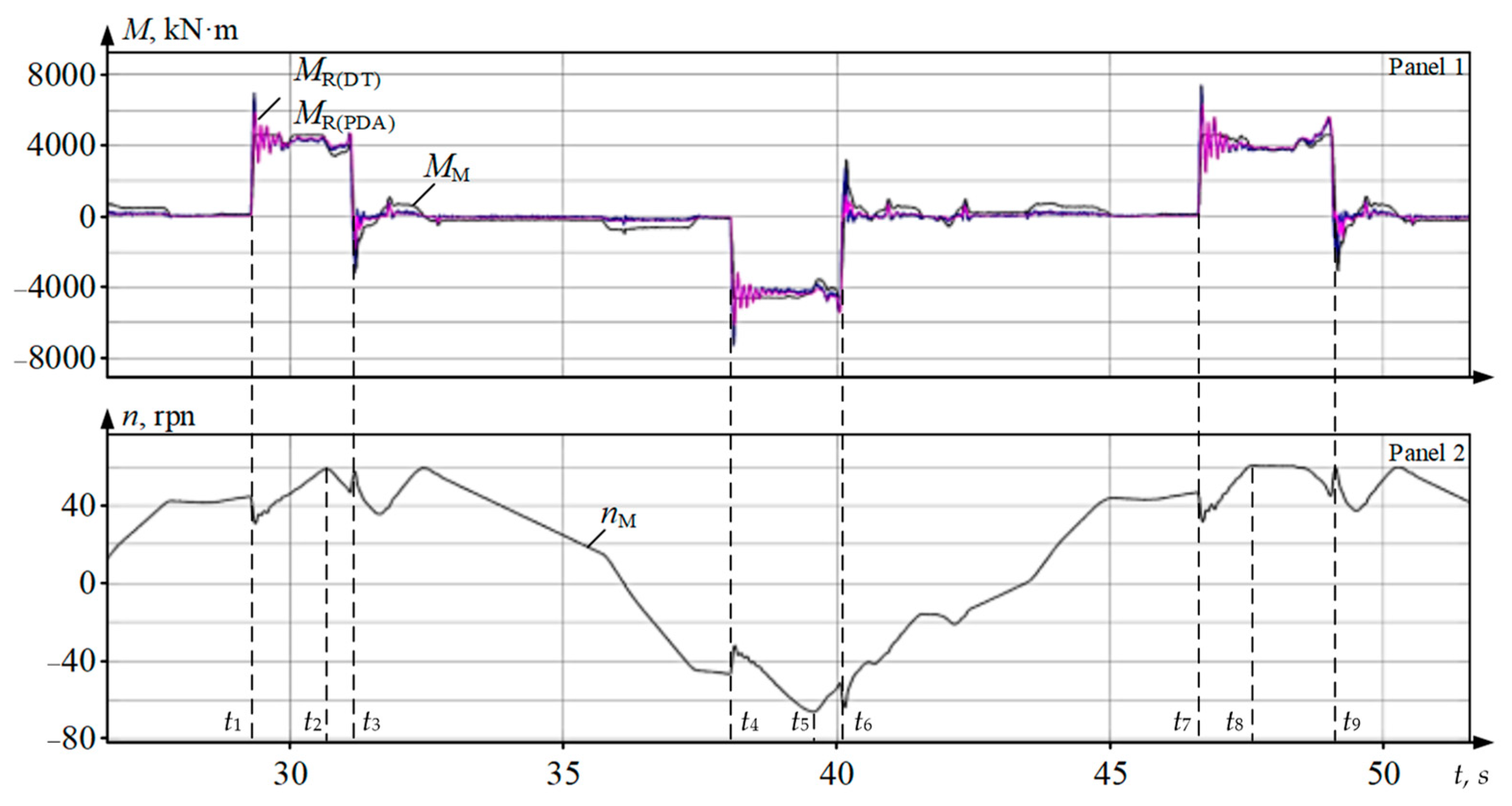
  • In all passes, biting occurs with closed angular gaps in the spindle joints.
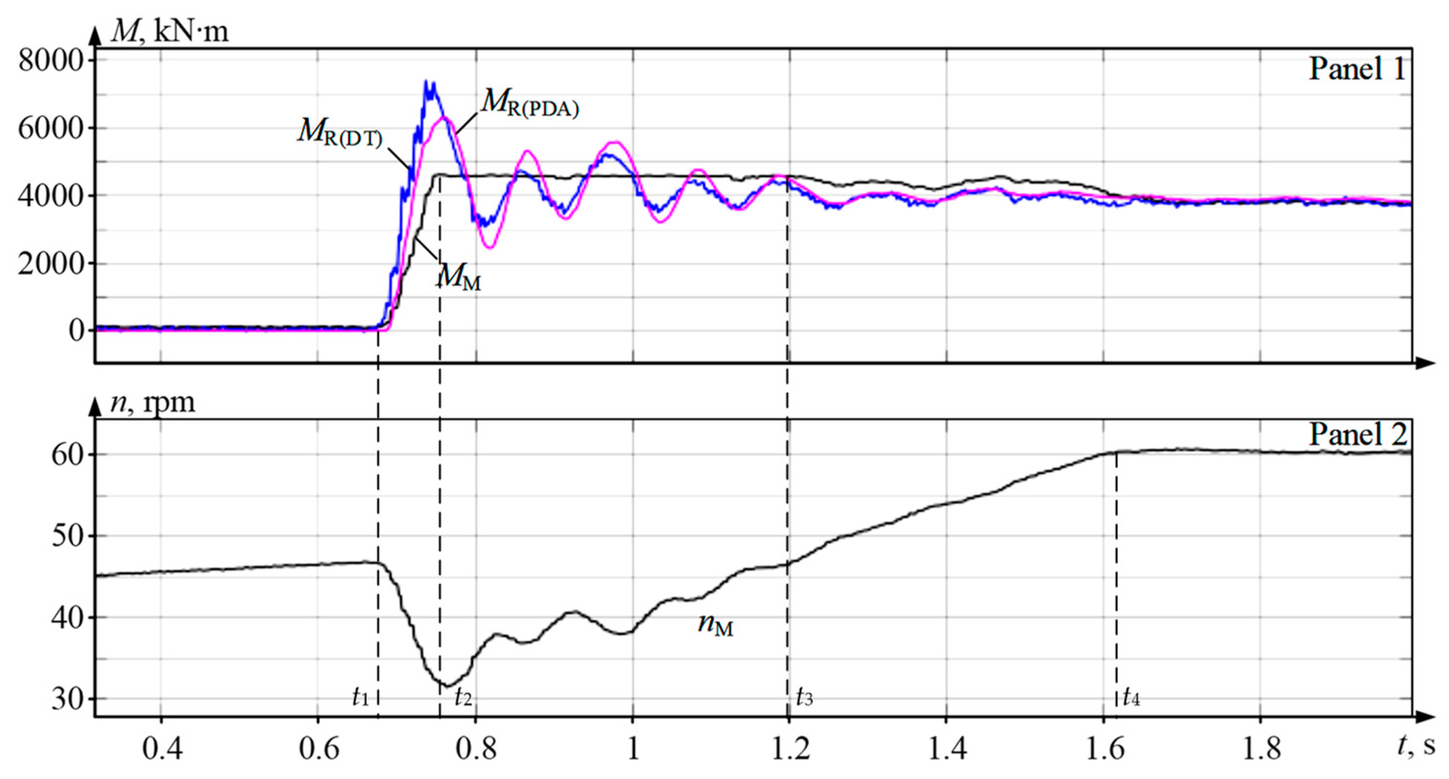
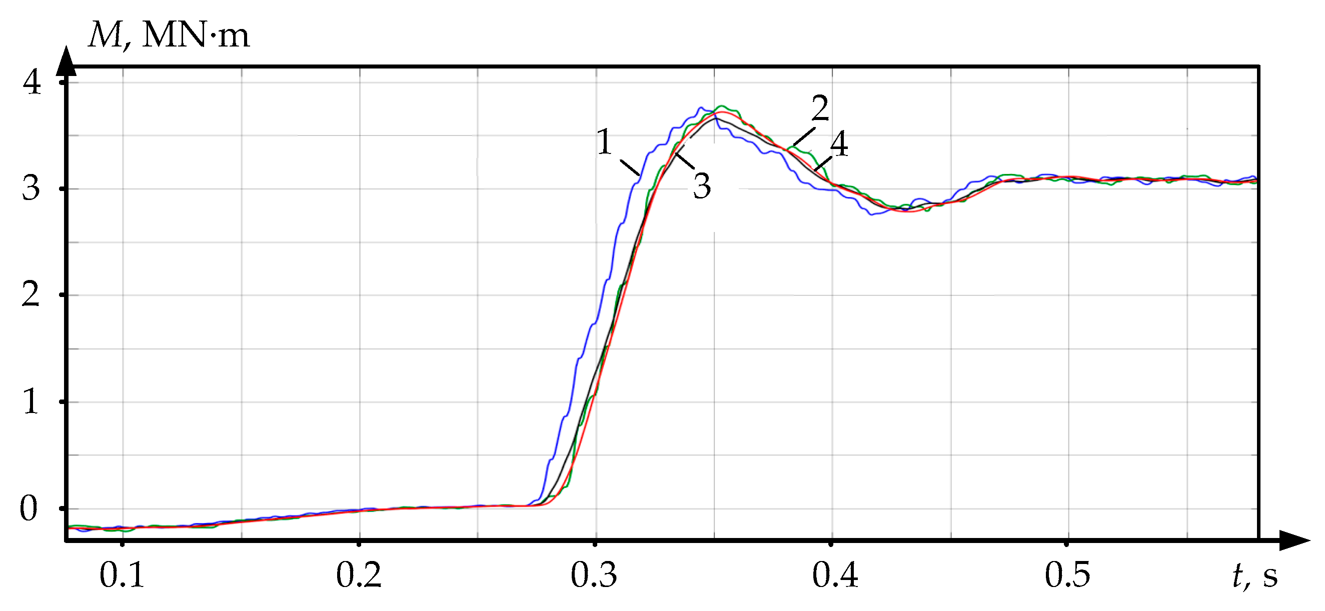
  • The full coincidence of the recovered MR(DT) and measured MR(PDA) torques confirms the reliability of the processes obtained during the VC of the developed observer.
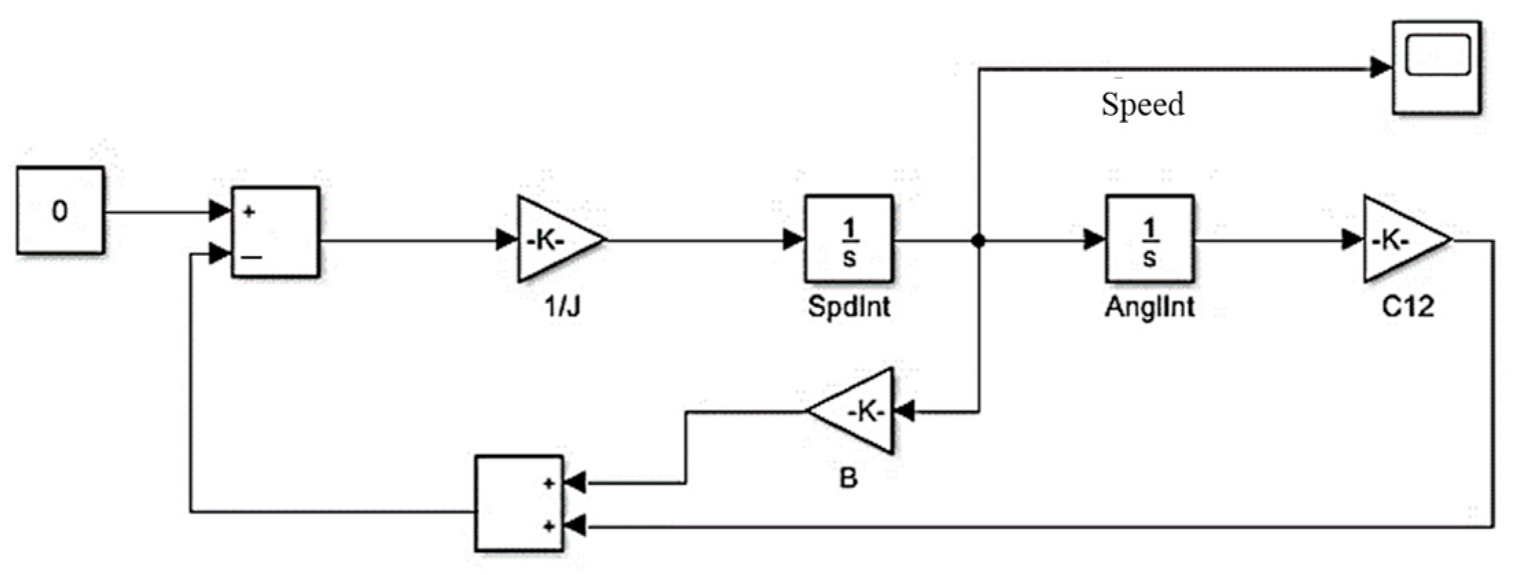
  • Time dependencies in Figure 11 and Figure 12 illustrate the adopted approach to configuring digital twins, according to which algorithms are debugged in Matlab Simulink with subsequent export to PLC software [12]. This facilitates configuration and reduces the VC costs of the electromechanical system.
Similar conclusions were drawn based on the oscillograms obtained for the lower roll drive (not shown here).
The method developed for calculating the virtual model parameters based on oscillograms of dynamic modes is recommended for use in the development of DTs of electromechanical systems. The described model is used to study transients and develop algorithms for limiting dynamic loads in the main lines of rolling stands.

5. Results and Discussion

To summarize the results and estimate the impact of angular gaps on the elastic torque recovery accuracy, rolling modes studies were compared for more than 150 workpieces with a gauge of 9 to 30 mm under various biting conditions. Figure 13 shows the average dependencies of the spindle torque amplitude with open and closed gaps (“gapped” and “gapless” diagrams, respectively). As noted above, the preliminary gap closing was facilitated by the drive acceleration; accordingly, gapped biting was provided by the short-term drive braking. The dependence “observer” of the elastic torque recovered using an observer is also shown here. The numerical values used to build these dependencies are given in Table 3.
The analysis of the data in the table allows the following conclusions to be made:
  • The recovery of the elastic torque by an observer, whose parameters have been determined using the developed method, is performed with an accuracy acceptable in the study of electromechanical systems. The maximum difference between the measured and recovered gapped values |ΔMmax|(Obs./Gap) = 4.7%, while the “gapped” curve parameters exceed those of the “observer” curve at all points. The respective gapless value |ΔMmax|(Obs./Gapl) = 5.9%, but the ‘gapless’ dependence coordinates are less than those on the “observer” curve. Thus, the recovered dependence occupies an intermediate position between the experimental curves. This allows the elastic torque (“observer”) recovery results to be considered acceptable for both the “gapless” and “gapped” cases.
  • The experiments confirm that closing the gaps at the moment of biting significantly increases the elastic torque amplitude (within 8.4–10%). With workpiece gauges of 9 and 30 mm, the amplitude differences are 8.4% (1.55 and 1.42 p. u.) and 9.6% (2.6 and 2.35 p. u.), respectively. This confirms the need for implementing control systems based on elastic torque observers to reduce the dynamic loads of the electromechanical systems of rolling mills [27].
General conclusion: the developed two-mass system coordinate position observer provided a satisfactory accuracy for parameter recovery and can be used in developing closed-loop elastic torque ACS.
The method proposed for determining the parameters of an electromechanical system model includes conducting the experiments with the engine running or stopped. It can be used for a wide class of electromechanical systems with elastic shafts under constant or variable load. The method is recommended for studying the equipment of any rolling mills, the electromechanical systems of which can be represented as two-mass models. In addition to the plate and wide-strip mills discussed, these include section rolling mills, sheet cold rolling mills, and some types of pipe rolling mills.
As noted above, the method is experimental. Within this approach, the system under study is essentially presented as a “black box”. Thus, there are no restrictions in terms of the complexity of the simulated electromechanical system. The method is applicable to two-mass and three-mass systems with an elastic shaft, which has been experimentally confirmed.
Since the method is not computational and does not involve the use of complex mathematical apparatus, no uncertainties arise in the process of determining the system parameters. The required parameters are defined during experiments, which can be conducted at specified intervals. This makes it possible to take into account changes in the dynamic behavior of the system, particularly regarding the wear of spindle connections. However, practical experience in operating electromechanical systems shows that such changes occur slowly. Thus, the standard service life of rolling mill spindles is 8 years (this is not always achieved). However, there is no need to consider the dynamic changes in the objects under study. These properties highlight the advantages of the experimental approach proposed.

6. Conclusions and Future Work

Studying the dynamic mode of the rolling stand electromechanical system at biting is an important problem. When using DTs in the development and virtual commissioning of automated drives, it is advisable to represent it as a two-mass model with an elastic shaft and angular gaps in the joints. This model reduces the quantity of software resources required to create DTs and thus allows DTs to be introduced in the PLC software.
A method for calculating the two-mass system virtual model parameters by using experimental data has been developed. Its key points are as follows:
  • calculating the 1st and 2nd mass inertia torques;
  • defining the stiffness coefficient of the mechanical transmission shaft;
  • defining the oscillation damping coefficient;
  • defining the time constants of the torque control loop transfer function.
The method is based on the analysis of oscillograms obtained in dynamic modes. The inertia torque is calculated based on the load-free drive acceleration transients. The elastic stiffness coefficient is defined by the motor emergency shutdown oscillograms with the metal in the rolls, obtained via a passive experiment. Similar oscillograms are used to define the oscillation damping coefficient. The approximation of the torque control loop in the two-mass system model using a filter with a time constant of 7–8 ms is justified. This allows the closed loop for controlling the motor air gap torque to be represented as a first-order link.
The reliability of the elastic torque recovery with satisfactory accuracy was confirmed by comparing the observer VC results and the experimentally recorded oscillograms. The calculation error of this parameter in the biting mode with closed angular gaps does not exceed 5.9%, and when gapped, does not exceed 4.7%. In this case, the largest difference in the elastic torque amplitudes due to the gaps closing at the moment of biting is 10%.
Thus, model validation was defined according to a “conventional” method of comparing the final calculation results with the experimental results. The criteria for determining the adequacy of the reconstructed and experimental data correspond to the generally accepted error, which is acceptable when modeling industrial electromechanical systems (in most cases, the discrepancy between the calculated and experimental data should not exceed 5%). As follows from the calculations above, the model under consideration provides such accuracy. For verification, this study used a method of comparing the sequence of events in a real system with the events occurring in the model, and that involved the interactive monitoring of the progress of modeling the dynamic modes for the systems under study. Since the two-mass model is generally accepted, no special attention was paid to this issue.
The electromechanical system VC technique has been applied, according to which control systems are configured using models in the Matlab Simulink package. Next, the models and algorithms are exported to the object controller software. The proposed method for configuring the observer is an example of implementing the DT technology at the stages of drive control system development and virtual commissioning. This field is considered in [12,27], and is considered promising regarding the development and improvement of the electromechanical and mechatronic systems of rolling mills.
State observers should form the backbone of rolling mill DTAs. Creating relatively simple object-oriented digital twins will contribute to the development of smart production and the transition of the metallurgical industry towards innovations [61,62,63,64]. Virtual models required to improve automated drives and mechatronic systems, including the described adequate two-mass model, facilitate this [65,66,67].
Building accessible virtual models reduces the materials and time spent on the implementation of digital technologies in operating industrial units. Exporting relatively simple object-oriented DTs to the PLC software facilitates their real implementation, which is the most important IoT problem.

Author Contributions

Methodology, A.S.K., V.R.K., A.A.R. and V.R.G.; ideas A.A.R., A.S.K. and B.M.L.; software B.M.L., V.R.G. and O.A.G.; validation M.A.Z.; formal analysis A.S.K. and V.R.K. All authors have read and agreed to the published version of the manuscript.

Funding

This work was financially supported by the Moscow Polytechnic University within the framework of the grant named after Pyotr Kapitsa.

Conflicts of Interest

The authors declare no conflict of interest.

References

  1. Falekas, G.; Karlis, A. Digital Twin in Electrical Machine Control and Predictive Maintenance: State-of-the-Art and Future Prospects. Energies 2021, 14, 5933. [Google Scholar] [CrossRef]
  2. Digital Twins and Virtual Commissioning in the Manufacturing Industry (Updated for 2023). Resources. 1 March 2022. Available online: https://www.visualcomponents.com/resources/blog/digital-twins-and-virtual-commissioning-in-industry-4-0/ (accessed on 23 August 2023).
  3. Bécue, A.; Maia, E.; Feeken, L.; Borchers, P.; Praça, I. A New Concept of Digital Twin Supporting Optimization and Resilience of Factories of the Future. Appl. Sci. 2020, 10, 4482. [Google Scholar] [CrossRef]
  4. Martínez-Olvera, C. Towards the Development of a Digital Twin for a Sustainable Mass Customization 4.0 Environment: A Literature Review of Relevant Concepts. Automation 2022, 3, 197–222. [Google Scholar] [CrossRef]
  5. Segovia, M.; Garcia-Alfaro, J. Design, Modeling and Implementation of Digital Twins. Sensors 2022, 22, 5396. [Google Scholar] [CrossRef] [PubMed]
  6. Abouzeid, A.F.; Trimpe, F.F.; Lück, S.; Traupe, M.; Guerrero, J.M.; Briz, F. Co-Simulation-Based Verification of Torsional Vibration Protection of Electric-Driven Railway Vehicle Wheelsets. Vibration 2022, 5, 613–627. [Google Scholar] [CrossRef]
  7. Fakhraian, E.; Semanjski, I.; Semanjski, S.; Aghezzaf, E.-H. Towards Safe and Efficient Unmanned Aircraft System Operations: Literature Review of Digital Twins’ Applications and European Union Regulatory Compliance. Drones 2023, 7, 478. [Google Scholar] [CrossRef]
  8. Yu, J.; Wen, Y.; Yang, L.; Zhao, Z.; Guo, Y.; Guo, X. Monitoring on Triboelectric Nanogenerator and Deep Learning Method. Nano Energy 2022, 92, 106698. [Google Scholar] [CrossRef]
  9. Digitalization in the Steel Industry/SMS Group#Magazine. Düsseldorf, 10 December 2017. Available online: https://www.sms-group.com/sms-group-magazine/overview/digitalization-in-the-steel-industry/ (accessed on 23 August 2023).
  10. The Digital Twin—More than a Virtual Representation of the Real World/SMS Group#Magazine. Düsseldorf. 3 November 2020. Available online: https://www.sms-group.com/jp/sms-group-magazine/overview/the-digital-twin-more-than-a-virtual-representation-of-the-real-world/ (accessed on 23 August 2023).
  11. Grieves, M.; Vickers, J. Digital Twin: Mitigating Unpredictable, Undesirable Emergent Behavior in Complex Systems. In Transdisciplinary Perspectives on Complex Systems; Springer: Berlin/Heidelberg, Germany, 2017; pp. 85–113. [Google Scholar] [CrossRef]
  12. Gasiyarov, V.R.; Bovshik, P.A.; Loginov, B.M.; Karandaev, A.S.; Khramshin, V.R.; Radionov, A.A. Substantiating and Implementing Concept of Digital Twins for Virtual Commissioning of Industrial Mechatronic Complexes Exemplified by Rolling Mill Coilers. Machines 2023, 11, 276. [Google Scholar] [CrossRef]
  13. Fuller, A.; Fan, Z.; Day, C.; Barlow, C. Digital Twin: Enabling Technologies, Challenges and Open Research. IEEE Access 2020, 8, 108952–108971. [Google Scholar] [CrossRef]
  14. Coito, T.; Faria, P.; Martins, M.S.E.; Firme, B.; Vieira, S.M.; Figueiredo, J.; Sousa, J.M.C. Digital Twin of a Flexible Manufacturing System for Solutions Preparation. Automation 2022, 3, 153–175. [Google Scholar] [CrossRef]
  15. VanDerHorn, E.; Mahadevan, S. Digital Twin: Generalization, characterization and implementation. Decis. Support Syst. 2021, 145, 113524. [Google Scholar] [CrossRef]
  16. Frederick, B. Control of Two Mass Electromechanical System. Eng. Technol. J. 2018, 3, 443–446. [Google Scholar] [CrossRef]
  17. Yu, Y.; Mi, Z. Dynamic Modeling and Control of Electromechanical Coupling for Mechanical Elastic Energy Storage System. J. Appl. Math. 2013, 2013, 603063. [Google Scholar] [CrossRef]
  18. Ismagilov, F.R.; Vavilov, V.E.; Sayakhov, I.F. Mathematical model of an aircraft electromechanical actuator with flex coupling. In Proceedings of the Dynamics of Systems, Mechanisms and Machines (Dynamics), Omsk, Russia, 14–16 November 2017. [Google Scholar] [CrossRef]
  19. Ju, J.; Liu, Y.; Zhang, C. Stability Analysis of Electromechanical Coupling Torsional Vibration for Wheel-Side Direct-Driven Transmission System under Transmission Clearance and Motor Excitation. World Electr. Veh. J. 2022, 13, 46. [Google Scholar] [CrossRef]
  20. Padilla-Garcia, E.A.; Rodriguez-Angeles, A.; ReséNdiz, J.R.; Cruz-Villar, C.A. Concurrent Optimization for Selection and Control of AC Servomotors on the Powertrain of Industrial Robots. IEEE Access 2018, 6, 27923–27938. [Google Scholar] [CrossRef]
  21. Yu, W.; Huang, Z.; Zhong, C.; Liu, J.; Yuan, Z. Method of Suppressing Torsional Vibration Noise of Automobile Drive-train System Based on DiscreteWavelet. J. Intell. Fuzzy Syst. 2020, 38, 7585–7594. [Google Scholar] [CrossRef]
  22. Lozynskyy, A.; Chaban, A.; Perzyński, T.; Szafraniec, A.; Kasha, L. Application of Fractional-Order Calculus to Improve the Mathematical Model of a Two-Mass System with a Long Shaft. Energies 2021, 14, 1854. [Google Scholar] [CrossRef]
  23. Popenda, A.; Szafraniec, A.; Chaban, A. Dynamics of Electromechanical Systems Containing Long Elastic Couplings and Safety of Their Operation. Energies 2021, 14, 7882. [Google Scholar] [CrossRef]
  24. Yildiz, S.K.; Forbes, J.F.; Huang, B.; Zhang, Y.; Wang, F.; Vaculik, V.; Dudzic, M. Dynamic modelling and simulation of a hot strip finishing mill. Appl. Math. Model. 2009, 33, 3208–3225. [Google Scholar] [CrossRef]
  25. Zhilenkov, A.A.; Kapitonov, A.A. The Synthesis of Precise Rotating Machine Mathematical Model, Operating Natural Signals and Virtual Data. IOP Conf. Ser. Mater. Sci. Eng. 2017, 221, 012003. [Google Scholar] [CrossRef]
  26. Radionov, A.A.; Gasiyarov, V.R.; Baskov, S.N.; Karandaev, A.S.; Khramshin, V.R. Mathematical modeling of mechatronics system «hydraulic screwdown mechanism—Electric drive of rolling mill stand». IOP Conf. Ser. Mater. Sci. Eng. 2018, 361, 012020. [Google Scholar] [CrossRef]
  27. Radionov, A.A.; Karandaev, A.S.; Gasiyarov, V.R.; Loginov, B.M.; Gartlib, E.A. Development of an Automatic Elastic Torque Control System Based on a Two-Mass Electric Drive Coordinate Observer. Machines 2021, 9, 305. [Google Scholar] [CrossRef]
  28. Wang, J.; Zhang, Y.; Xu, L.; Jing, Y.; Zhang, S. Torsional vibration suppression of rolling mill with constrained model predictive control. In Proceedings of the 6th World Congress on Intelligent Control and Automation (WCICA), Dalian, China, 21–23 June 2006; pp. 6401–6405. [Google Scholar] [CrossRef]
  29. Shahgholian, G.; Shafaghi, P. Simple analytical and robust controller design for two-mass resonant system. In Proceedings of the Second International Conference on Computer and Electrical Engineering (ICCEE), Dubai, United Arab Emirates, 28–30 December 2009; pp. 245–248. [Google Scholar] [CrossRef]
  30. Karandaev, A.S.; Loginov, B.M.; Gasiyarov, V.R.; Khramshin, V.R. Force limiting at roll axial shifting of plate mill. Procedia Eng. 2017, 206, 1780–1786. [Google Scholar] [CrossRef]
  31. Gasiyarov, V.R.; Khramshin, V.R.; Voronin, S.S.; Lisovskaya, T.A.; Gasiyarova, O.A. Dynamic torque limitation principle in the main line of a mill stand: Explanation and rationale for use. Machines 2019, 7, 76. [Google Scholar] [CrossRef]
  32. Klinkov, M.; Feist, R. The Virtual Rolling Mill—Enhancing Product Development and Commissioning. Mater. Sci. Forum 2016, 854, 231–236. [Google Scholar]
  33. Magomadov, V. The Digital Twin Technology and its Role in Manufacturing. IOP Conf. Ser. Mater. Sci. Eng. 2020, 862, 032080. [Google Scholar] [CrossRef]
  34. Szczepanski, R.; Kaminski, M.; Tarczewski, T. Auto-Tuning Process of State Feedback Speed Controller Applied for Two-Mass System. Energies 2020, 13, 3067. [Google Scholar] [CrossRef]
  35. Shahgholian, G. Modeling and Simulation of a Two-Mass Resonant System with Speed Controller. Int. J. Inf. Electron. Eng. 2013, 5, 448–452. [Google Scholar] [CrossRef]
  36. Singh, M.; Srivastava, R.; Fuenmayor, E.; Kuts, V.; Qiao, Y.; Murray, N.; Devine, D. Applications of Digital Twin across Industries: A Review. Appl. Sci. 2022, 12, 5727. [Google Scholar] [CrossRef]
  37. Serkies, P.; Szabat, K. Effective damping of the torsional vibrations of the drive system with an elastic joint based on the forced dynamic control algorithms. J. Vib. Control. 2019, 25, 2225–2236. [Google Scholar] [CrossRef]
  38. Dodds, S.J.; Szabat, K. Forced Dynamic Control of Electric Drives with Vibration Modes in the Mechanical Load. In Proceedings of the 12th International Power Electronics and Motion Control Conference, Portoroz, Slovenia, 30 August–1 September 2006. [Google Scholar]
  39. Kolganov, A.R.; Lebedev, S.K.; Nests, N.E. Electromechanotronic Systems. Modern Control, Implementation, and Application Techniques; Infra-Engineering: Moscow/Vologda, Russia, 2019. [Google Scholar]
  40. Zhang, R.; Yang, Y.; Chen, Z.; Tong, C. Torsional Vibration Suppression Control in the Main Drive System of Rolling Mill by State Feedback Speed Controller Based on Extended State Observer. In Proceedings of the IEEE International Conference on Control and Automation, Guangzhou, China, 30 May–1 June 2007; pp. 2172–2177. [Google Scholar] [CrossRef]
  41. Drozdz, K.; Janiszewski, D.; Szabat, K. Application of fuzzy Kalman filter in adaptive control structure of two-mass system. In Proceedings of the 16th International Power Electronics and Motion Control Conference and Exposition, Antalya, Turkey, 21–24 September 2014. [Google Scholar] [CrossRef]
  42. Pajchrowski, T.; Janiszewski, D. Control of multi-mass system by on-line trained neural network based on Kalman filter. In Proceedings of the 17th European Conference on Power Electronics and Applications (EPE’15 ECCE-Europe), Geneva, Switzerland, 8–10 September 2015. [Google Scholar] [CrossRef]
  43. Qiao, F.; Zhu, Q.M.; Li, S.Y.; Winfield, A. Torsional vibration suppression of a 2-mass main drive system of rolling mill with KF enhanced pole placement. In Proceedings of the 4th World Congress on Intelligent Control and Automation, Shanghai, China, 10–14 June 2002. [Google Scholar] [CrossRef]
  44. Dhaouadi, R.; Kubo, K.; Tobise, M. Two-degree-of-freedom robust speed controller for high performance rolling mill drives. In Proceedings of the Conference Record of the IEEE Industry Applications Society Annual Meeting, Houston, TX, USA, 4–9 October 1992. [Google Scholar] [CrossRef]
  45. Saarakkala, S.E.; Hinkkanen, M. State-space speed control of two-mass mechanical systems: Analytical tuning and experimental evaluation. IEEE Trans. Ind. Applicat. 2014, 5, 3428–3437. [Google Scholar] [CrossRef]
  46. Ke, C.; Wu, A.; Bing, C. Mechanical parameter identification of two-mass drive system based on variable forgetting factor recursive least squares method. Trans. Inst. Meas. Control. 2019, 41, 494–503. [Google Scholar] [CrossRef]
  47. Zhou, C.; Shen, Y. A PID Control Method Based on Internal Model Control to Suppress Vibration of the Transmission Chain of Wind Power Generation System. Energies 2022, 15, 5919. [Google Scholar] [CrossRef]
  48. Wahrburg, A.; Jelavic, E.; Klose, S.; Listmann, K.D. Robust Semi-Automatic Identification of Compliantly Coupled Two-Mass Systems. IFAC-PapersOnLine 2017, 50, 14569–14574. [Google Scholar] [CrossRef]
  49. Kabziński, J.; Mosiołek, P. Integrated, Multi-Approach, Adaptive Control of Two-Mass Drive with Nonlinear Damping and Stiffness. Energies 2021, 14, 5475. [Google Scholar] [CrossRef]
  50. Saarakkala, S.E.; Hinkkanen, M. Identification of Two-Mass Mechanical Systems Using Torque Excitation: Design and Experimental Evaluation. IEEE Trans. Ind. Appl. 2015, 51, 4180–4189. [Google Scholar] [CrossRef]
  51. Niu, Z.; Huang, W.; Zhu, S. Online Identification of Mechanical Systems Using the Simplified Output Error Model. IEEE Trans. Ind. Electron. 2023, 70, 6653–6662. [Google Scholar] [CrossRef]
  52. Salman, M.; Khan, H.; Lee, M.C. Perturbation Observer-Based Obstacle Detection and Its Avoidance Using Artificial Potential Field in the Unstructured Environment. Appl. Sci. 2023, 13, 943. [Google Scholar] [CrossRef]
  53. Radionov, A.A.; Gasiyarov, V.R.; Karandaev, A.S.; Khramshin, V.R. Use of automated electric drives for limiting dynamic loads in shaft lines of roll mill stands. J. Eng. 2019, 17, 3578–3581. [Google Scholar] [CrossRef]
  54. Zhong, B.; Deng, B.; Zhao, H. Simulation Model and Method for Active Torsional Vibration Control of an HEV. Appl. Sci. 2019, 9, 34. [Google Scholar] [CrossRef]
  55. Gasiyarova, O.A.; Karandaev, A.S.; Erdakov, I.N.; Loginov, B.M.; Khramshin, V.R. Developing Digital Observer of Angular Gaps in Rolling Stand Mechatronic System. Machines 2022, 10, 141. [Google Scholar] [CrossRef]
  56. Karandayev, A.S.; Loginov, B.M.; Zinchenko, M.A.; Mazitov, D.M.; Podolko, A.S. Speed Coordination System for Electric Drives of a Plate Mill Stand: Theory and Development. In Proceedings of the International Ural Conference on Electrical Power Engineering (UralCon), Magnitogorsk, Russian, 24–26 September 2021. [Google Scholar] [CrossRef]
  57. Radionov, A.A.; Gasiyarov, V.R.; Tverskoi, M.M.; Khramshin, V.R.; Loginov, B.M. Implementation of telemetric on-line monitoring system of elastic torque of rolling mill line of shafting. In Proceedings of the 2nd International Ural Conference on Measurements (UralCon), Chelyabinsk, Russia, 16–19 October 2017; pp. 450–455. [Google Scholar] [CrossRef]
  58. Morozova, Z.G. Studying Damped Oscillations of Torsion Pendulum and Oscillatory Capacitor Discharge; VyatGU Publishing House: Kirov, Russian, 2015; Available online: https://poisk-ru.ru/s170t17.html (accessed on 1 July 2023).
  59. Terekhov, V.M.; Osipov, O.I. Drive Control Systems; Academy Publishing Center: Moscow, Russian, 2006. [Google Scholar]
  60. Gasiyarov, V.R.; Radionov, A.A.; Loginov, B.M.; Karandaev, A.S.; Gasiyarova, O.A.; Khramshin, V.R. Development and Practical Implementation of Digital Observer for Elastic Torque of Rolling Mill Electromechanical System. J. Manuf. Mater. Process. 2023, 7, 41. [Google Scholar] [CrossRef]
  61. Bărbulescu, C.; Căiman, D.-V.; Dragomir, T.-L. Parameter Observer Useable for the Condition Monitoring of a Capacitor. Appl. Sci. 2022, 12, 4891. [Google Scholar] [CrossRef]
  62. Nahri, S.N.F.; Du, S.; van Wyk, B.J. Predictive Extended State Observer-Based Active Disturbance Rejection Control for Systems with Time Delay. Machines 2023, 11, 144. [Google Scholar] [CrossRef]
  63. Liu, Y.; Song, B.; Zhou, X.; Gao, Y.; Chen, T. An Adaptive Torque Observer Based on Fuzzy Inference for Flexible Joint Application. Machines 2023, 11, 794. [Google Scholar] [CrossRef]
  64. Iqteit, N.A.; Yahya, K.; Makahleh, F.M.; Attar, H.; Amer, A.; Solyman, A.A.A.; Qudaimat, A.; Tamizi, K. Simple Mathematical and Simulink Model of Stepper Motor. Energies 2022, 15, 6159. [Google Scholar] [CrossRef]
  65. Dang, S.; Kong, Z.; Peng, L.; Ji, Y.; Zhang, Y. Adaptive State Observer for Robot Manipulators Diagnostics and Health Degree Assessment. Appl. Sci. 2020, 10, 514. [Google Scholar] [CrossRef]
  66. Sami, I.; Ullah, S.; Ullah, S.; Bukhari, S.S.H.; Ahmed, N.; Salman, M.; Ro, J.-S. A Non-Integer High-Order Sliding Mode Control of Induction Motor with Machine Learning-Based Speed Observer. Machines 2023, 11, 584. [Google Scholar] [CrossRef]
  67. Short, M.; Twiddle, J. An Industrial Digitalization Platform for Condition Monitoring and Predictive Maintenance of Pumping Equipment. Sensors 2019, 19, 3781. [Google Scholar] [CrossRef]
Figure 1. The layout of the upper and lower roll motors (a) and the upper roll spindle (b) of the mill 5000 stand: 1 is the sensor; 2 is the spindle shaft; 3 is the telemetry ring; 4 is the spindle head; and 5 is the upper backup roll.
Jmmp 07 00183 g001
Figure 2. Block diagram of the drive control system with implementing the functions of emerging upward bend and load division: Sref(t) and Vref(t)—motion trajectory and speed, set as points; V(t)—drive speed setting generated by the interpolator.
Jmmp 07 00183 g002
Figure 3. Kinematic diagram of the transmission (a) and block diagram of the two-mass electromechanical system (b): 1 is the speed controller; 2 is the speed closed loop; 3 and 8 are the transfer functions of the 1st and 2nd inertial links of the two-mass system (motor and roll); 4 is the integrating link; 5 is the link simulating the angular gap; 6 is the mechanical transmission elasticity coefficient; 7 is the elastic oscillation damping unit; and 9 is the first mass (motor) speed feedback coefficient.
Jmmp 07 00183 g003
Figure 4. The two-mass system model for the development of an observer (a) and in a matrix form (b).
Jmmp 07 00183 g004aJmmp 07 00183 g004b
Figure 5. Block diagram of the observer of elastic torque MR(DT) and the 2nd mass speed.
Jmmp 07 00183 g005
Figure 6. Acceleration oscillograms of drives without metal in the rolls: window 1—MM(U), MS(U)—upper roll motor and spindle torques; window 2—MM(L), MS(L)—the same for the lower roll; window 3—V0(U), V0(L) speed settings and upper and lower roll speeds (coincide); window 4—n(U), n(L) speeds of UMD and LMD motors.
Jmmp 07 00183 g006
Figure 7. Oscillogram (a) and calculated dependence (b) of the motor speed during its emergency shutdown with metal in the rolls (sticking).
Jmmp 07 00183 g007aJmmp 07 00183 g007b
Figure 8. Two-mass system model in Matlab Simulink to define the damping coefficient.
Jmmp 07 00183 g008
Figure 10. LAFC and LPFC of the motor torque closed loop when approximated by the 1st- and 2nd-order filters.
Jmmp 07 00183 g010
Figure 11. Transients of the upper roll spindle elastic torque at the biting and acceleration.
Jmmp 07 00183 g011
Figure 12. The spindle elastic torque and motor speed transients for three passes.
Jmmp 07 00183 g012
Figure 13. Dependences of the biting torque amplitude, obtained experimentally and recovered by the observer.
Jmmp 07 00183 g013
Table 1. Source data for defining the two-mass system parameters.
ParameterUnit of MeasureValue
Motor inertia torquekg∙m2125,000
Work roll weightkg63,000
Work roll diameterkg1.2
Support roll weightkg226,400
Support roll diameterm2.3
Table 2. The dynamic torques defined by the oscillograms.
Roll DriveDynamic Torque, kN∙mAcceleration, rps2Inertia Torque, kg∙m2
MotorSpindlerps2rad/s2Total1st Mass2nd Mass
Upper260800.46/21.445179,900124,53755,363
Lower250650.46/21.445173,010128,02744,983
Table 3. Calculated biting torque amplitudes.
GaugeMeasured ValuesObserver Values
Mmax
(Gapped)
Mmax
(Gapless)
ΔMmax
(Gap/Gapl.)
Mmax
(Obs.)
Mmax|
(Obs./Gap)
Mmax|
(Obs./Gapl.)
mmp.u.p.u.p.u.%p.u.p.u.%p.u.%
91.551.420.138.41.480.074.50.064.2
121.71.530.1710.01.620.084.70.095.9
181.921.740.189.31.830.094.70.095.2
242.42.190.218.82,30.14.20.115.0
302.62.350.259.62.480.124.60.135.5
Disclaimer/Publisher’s Note: The statements, opinions and data contained in all publications are solely those of the individual author(s) and contributor(s) and not of MDPI and/or the editor(s). MDPI and/or the editor(s) disclaim responsibility for any injury to people or property resulting from any ideas, methods, instructions or products referred to in the content.

