Article

Impact of Green Ceramic Hybrid Machining (GCHM) on Reliability and Repeatability of the Properties of Sintered Yttrium-Tetragonal Zirconia Polycrystal Parts

1
Machine Design and Production Engineering Lab, Research Institute for Science and Material Engineering, UMONS, 7000 Mons, Belgium
2
Science and Technology Research Unit, Haute Ecole Provinciale de Hainaut Condorcet, 6000 Charleroi, Belgium
3
Research and Technological Support Departement, Environmental Materials Research Association, INISMa, CRIBC, 7000 Mons, Belgium
4
Optec Laser Systems, 7080 Frameries, Belgium
5
Department of Mechanical Engineering, KU Leuven, 3001 Leuven, Belgium
*
Author to whom correspondence should be addressed.
J. Manuf. Mater. Process. 2023, 7(3), 118; https://doi.org/10.3390/jmmp7030118
Submission received: 18 May 2023 / Revised: 17 June 2023 / Accepted: 19 June 2023 / Published: 20 June 2023
(This article belongs to the Special Issue Advances in Machining of Difficult-to-Cut Materials)

Abstract

:
The innovative Green Ceramic Hybrid Machining (GCHM) process sequentially combines milling with a cutting tool (GCM, Green Ceramic Machining) and laser beam machining (GCLBM) of a ceramic material (black Y-TZP in this study) at the green stage mainly to increase productivity, avoid taper angle limitations of laser beam machining, and obtain micro-features. The study focuses on the reliability and the repeatability of the properties of sintered parts obtained by three manufacturing processes (GCM, GCLBM, GCHM) to assess the performance of hybridisation. It turns out that GCHM is a compromise of both milling and laser beam processes; it increases the repeatability of the surface quality and it slightly reduces (less than 7%) the flexural strength by comparison to milling for a similar reliability. The study also highlights that the surface quality of GCLBM processed parts relies on of the surface generated by the previous operation. Milling that surface at the previous step is therefore recommended, corresponding to the sequence adopted by GCHM.

1. Introduction

Engineering ceramics (also called technical ceramics) are very competitive compared to polymer and metallic materials thanks to their high mechanical properties (e.g., high hardness and high wear resistance) at high temperatures (characteristics that make them well-suited for use as cutting tool materials [1]) and in corrosive environments, as well as, for some of them, biocompatibility, chemical inertia, or electrical isolation [2]. The ceramic material studied in this work, zirconium dioxide (ZrO 2 , also called zirconia), is one of the most used in modern industries, including heat engines, biomedicine, and the food and luxury sectors [2,3,4,5]. When zirconia is stabilised in a metastable state, with yttria oxides, for example, such as in Yttrium-Tetragonal Zirconia Polycrystal (Y-TZP), a martensitic phase transformation from tetragonal (t) to monoclinic (m) can occur at room temperature when stress is applied [6]. This phase transformation goes along with a volume expansion of up to 5% [6]. In the case of a propagating crack, the stress can be large enough (e.g., at the crack tip) to initiate the phase transformation. It generates, in turn, a volume expansion and shear stresses that induce compressive stresses against the crack propagation. This enhances the toughness of the material. This phenomenon is called transformation toughening and leads to a “crack shielding” effect [6]. Thanks to this, stabilised zirconia exhibits the best flexural strength, 500–1800 MPa according to Ferraris et al. [2], (900–1400 MPa according to Pereira et al. [7]) and fracture toughness, 4–12 MPa m [2] 5–9 MPa m [7]), amongst advanced ceramics [2]. The toughening transformation of Y-TZP also improves its Vickers hardness [7]. Zirconia is classified in bioceramics, one of the four classes of materials (along with biopolymers, biocomposites, and biometals) with clinical applications for implants and biomedical devices [8]. Biocompatibility, surface bond to tissue and corrosion resistance, are its main advantages leading to applications in medical implants for hip, shoulder, knee, dental, and joints, as highlighted by [2,9]. An m-phase fraction of less than 20% is recommended by ISO 13356 [10] for medical implant applications. It must, therefore, be checked that the manufacturing chain of such components fulfils this requirement.
The shaping of engineering ceramic components is very laborious because of its properties and the number of steps that must be mastered. Often, a finishing step is essential at the end of the manufacturing chain to reduce the defects generated in the previous steps. The cost of this last step can be worth 80% of the total cost to produce a ceramic part [2]. If micro-cracks are generated in a step (e.g., by machining), the final properties of the component could be considerably reduced [11].
Machining at the hard (or sintered) stage (usually by grinding) leads to two consequences:
  • Compressive residual stresses can be induced as a consequence of plastic deformation and, thus, of the t m transformation [12]. A large transformation depth leads to a degradation of mechanical properties due to the presence of deep cracks that overcome the benefits of the transformation [13]. A low fraction of m-phase is, therefore, recommended [12].
  • Surface defects (such as micro-cracks ranging from 50 to 200 μ m [11]) can be generated, introducing stress concentrations that decrease the flexural strength. A correlation between surface roughness and flexural strength was observed after grinding; the main influencing factor is the number of surface defects that increases with the surface roughness. This explains the higher flexural strength after grinding than after milling [13,14]. Milling at the pre-sintered stage allows to benefit from a ductile behaviour of Y-TZP that contributes to reducing surface defects [15].
Laser beam machining (LBM) is an alternative to shape ceramic materials while reducing micro-cracks generation thanks to the absence of force created by tool contact. Nevertheless, machining with a laser is dependent on fluence, making the ablation depth difficult to master [16]. It can influence the surface roughness [16], produce severe surface damage, as well as modifications in the microstructure or in the composition of the ceramic material [17]. It must be noted that LBM is also increasingly used to texture metallic components [18] and cutting tools [16]. The heat-affected zone (HAZ) generated by a nanosecond laser beam is characterised by micro-cracks, remelted material or recrystallisation [17]. The material removal rate of LBM is low by comparison with machining, but LBM enables the obtaining of micro-features and fine details thanks to the small spot size [19]. The laser parameters play a key role in the modifications of the surface and of the microstructure, and in the damage caused by heat exchange.
Ceramic materials can also be machined at the green stage [20] to reduce time and costs of about 10 and 20 times, respectively, in comparison to the hard stage [21]. A green ceramic blank consists of compacted ceramic powders held by a binder before the sintering operation. Green ceramic milling (with a cutting tool, GCM) allows the ceramic material to be machined while minimising the risk of generating significant micro-cracks that can lead to premature failure of the ceramic part [22]. LBM can also be carried out at the green stage (i.e., GCLBM), but the generation of hot spots must then be reduced as much as possible to avoid a decrease in the mechanical properties of the sintered part [23,24].
In this research, a new manufacturing process to machine ceramic parts at the green stage is introduced, the Green Ceramic Hybrid Machining (GCHM), which is a sequential combination of milling and laser beam machining at the green stage (GCM and GCLBM). GCHM enables an increase in productivity, reduction in the size of the features to be fabricated (miniaturisation and micro-fabrication), and avoidance of taper angle limitations by using the advantages of each process. Combinations of laser and mechanical machining can be found in the literature to constitute either a laser-assisted mechanical machining process [25], which is a completely different approach to this work, either a hybrid machining process for a wrought material [26]. In their work, Hao et al. [26] machined oxygen-free copper by combining laser and milling processes. The nature (metal vs. ceramic) and the processing path (wrought vs. powder) are completely different, as well as the order of the combination of the two processes. Indeed, Hao et al. first used laser and then milling to maximize material removal rate and ensure surface quality. In this study, milling enables the performance of the roughing operation, followed by laser for the finishing operation. The goal is to maximize productivity, but also to ensure machining quality considering both the machined surface quality and the mechanical properties of the component, while ensuring that the manufactured component is suitable for medical implants applications.
This paper investigates the GCHM process on Y-TZP. This innovative approach combines the novelty of hybridation with the stage at which it occurs, the green state of the ceramic material. The impact of this new process on reliability and repeatability of the properties of the final sintered part is evaluated. The results of GCHM are compared to GCM and GCLBM to assess the performance and the relevance of this new hybrid process for green ceramic machining, as well as the manufacturing of implants for surgery.

2. Materials and Methods

2.1. Material

Green blanks (66 mm × 66 mm × 15 mm) of black Y-TZP are manufactured by the Belgian Ceramic Research Centre (BCRC), Mons, Belgium [20]. They are made of fine (particles size around 100 nm with a specific surface area of 7 m 2 / g ) Yttria Stabilized Zirconia powder (3 mol% yttria-TZ-3Y-SE-Tosoh Corporation, Tokyo, Japan) and an organic binder (2 wt%, Zusoplast-Zschimmer and Schwartz, Koblenz, Germany). To promote laser ablation by improving the absorptivity of the green, a Dispersed Absorptive Solid Inorganic Material (DASIM) is added in the powder following a patent [20]. It is degraded above a threshold temperature lower than the sintering temperature.
Uniaxial compaction at 37 MPa is applied, followed by isostatic compaction at 195 MPa during 5 min. The steps for preparing samples from a blank are listed hereunder:
  • The blank upper surface is machined with one of the processes (GCM, GCLBM, GCHM) based on previously optimised parameters [22,23,27];
  • All the blanks are sintered in the same conditions in a furnace following this sequence:
    • Room temperature to 250 ° C at a rate of 1 ° C /min;
    • 250 ° C for 2 h ;
    • 250 ° C to 750 ° C at a rate of 1 ° C /min;
    • 750 ° C for 2 h ;
    • 750 ° C to 1430 ° C at a rate of 3 ° C /min;
    • 1430 ° C for 2 h ;
    • 1430 ° C to room temperature at a rate of 5 ° C /min.
  • The samples (12 for each process) are cut with a diamond disk at the dimensions recommended by EN 843 [28] and provided in Table 1;
  • All surfaces except the machined ones are polished with SiC of meshes 220#, 500#, 800#, 1200#, 2400#, and 4000#, then on a felt with 3–6 μ m diamond paste (for 4–5 min for each step).
In addition, a set of 12 samples is processed according to EN 843 [29] (i.e., grinding after sintering) to act as reference.
Table 2 shows the processes parameters, as obtained from earlier research [22,23], to machine the samples. For GCHM, GCM is followed by GCLBM with the same parameters as in Table 2. This order (GCM before GCLBM) has been chosen to benefit from the advantages of each separate process. In this configuration, GCM can be seen as the roughing stage maximizing productivity, and GCLBM acts as the finishing stage to obtain small features, below the range that can be achieved with GCM.

2.2. Measurements

After sintering, phase destabilisation and surface roughness measurements are carried out on the machined surfaces before a three-point bending test of each sample. Destabilisation of the tetragonal phase is characterized by highlighting phase components. The percentage of monoclinic phase components is computed for 5 samples (per process) by XRD measurements with a Siemens D5000 (Siemens, Munich, Germany) diffractometer θ / 2 θ . The fraction of phase component is computed by Equations (1) and (2) [30,31]
X m = I m ( 1 ¯ 11 ) + I m ( 111 ) I m ( 1 ¯ 11 ) + I m ( 111 ) + I t ( 111 )
X t = I t ( 111 ) I m ( 1 ¯ 11 ) + I m ( 111 ) + I t ( 111 )
where X m and X t are the fraction of the monoclinic and the tetragonal ZrO 2 phases, respectively, and I m and I t are the intensities of the monoclinic and the tetragonal ZrO 2 reflections, respectively.
On the 5 samples per process analysed by XRD, arithmetic and total surface roughness values ( R a and R t ) are measured on 3 distinct areas (resulting in 15 measurements per process). Surface roughness values are provided by Diavite DH-6 (Diavite, Bülach, Switzerland) contact roughness measurement equipment following the ISO 4288 standard [32].
Fracture strength is characterized (according to EN 843 [29]) by three-point bending tests performed on a Zwick Z100 (Zwick-Roell GmbH & Co. KG, Ulm, Germany) universal testing machine on all samples (12 samples per process). The sample is positioned on an alumina tooling with the machined surface in tension.

2.3. Failure Analysis

Due to the brittle behaviour of ceramic materials, a significant dispersion of their mechanical properties is observed for different samples from the same production batch. The distribution around the mean value is generally not normal but asymmetrical. The Weibull distribution with two parameters is recommended by EN 843 [29] to characterise the failure behaviour of ceramic materials. The probability of failure, P f , for a bending test is given by
P f = 1 exp [ ( σ f σ 0 ) k ]
with:
  • σ f > 0 : the flexural strength of a sample from the batch, computed by σ f = 3 F l 2 b h 2 with F the peak force at fracture, l the distance between the centres of the inner and outer support rollers, and b and h the width and the thickness of the sample, respectively ( P f = 0 if σ f 0 ).
  • σ 0 : the Weibull characteristic strength of the batch, it is a normalising factor and represents the strength of the sample with a probability of failure of 63.2%.
  • k: the Weibull modulus, it is an image of the defects distribution (cracks, voids) inside the material and represents the dispersion of the values (the higher k, the smaller the dispersion and the safer the material) [2]. Weibull modulus values are usually 10 or less for brittle materials such as ceramic materials (values for ductile metals are from 10 to 200) [33].
A ranking number, i, is given to each of the N = 12 samples of the batch and a probability value, P f , i , is estimated by:
P f , i = i 0.5 N
Flexural strengths are arranged in an increasing order and plotted with
x i = ln ( σ f , i )
and
y i = ln [ ln ( 1 1 P f , i ) ]
to generate a Weibull diagram. Estimations of the Weibull modulus, k ^ , and the Weibull characteristic strength, σ ^ 0 , are determined with the maximum-likelihood method following EN 843 [29]:
j = 1 N σ f , j k ^ ln ( σ f , j ) j = 1 N σ f , j k ^ 1 N j = 1 N σ f , j 1 k ^ = 0
σ 0 = [ ( j = 1 N σ f , j k ^ ) 1 N ] 1 k ^
The estimation of Weibull modulus, k ^ , is then corrected by a coefficient obtained with the Monte Carlo method [29]. Following the standard [29], no correction is needed for the characteristic strength, σ ^ 0 , as its bias is minimal. A 90% confidence interval is computed for both Weibull parameters as specified by EN 843 [29]. Figure 1 shows the Weibull diagram for a black Y-TZP reference part (classical manufacturing chain) where the slope is k and the intersection with x-axis is σ 0 . It allows to assess the suitability of the two-parameter Weibull distribution, as well as the confidence level. This check is successfully passed for the four studied processes.

3. Results

3.1. Surface Roughness

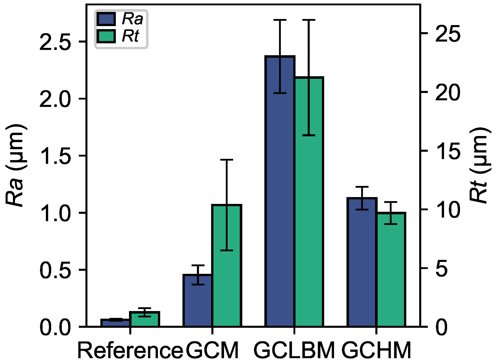
Figure 2 shows the arithmetic roughness, R a , and the total roughness, R t , values for each of the three processes and the reference. The lowest values are obtained with the reference, while the highest ones are produced by GCLBM with values around R a = 2.5 μ m and R t = 20 μ m ; as is also the case for the deviation around the mean value. Total roughness values are similar, around 10 μ m , for GCM and GCHM but with a lower deviation for GCHM.
Arithmetic roughness value of GCHM is twice as much as in GCM but it achieves, still, a R a close to 1.1 μ m on average. Low surface roughness (typical value: R a < 1.6 μ m for contact applications) is required to avoid the risk of crack initiation.

3.2. Phase Destabilisation

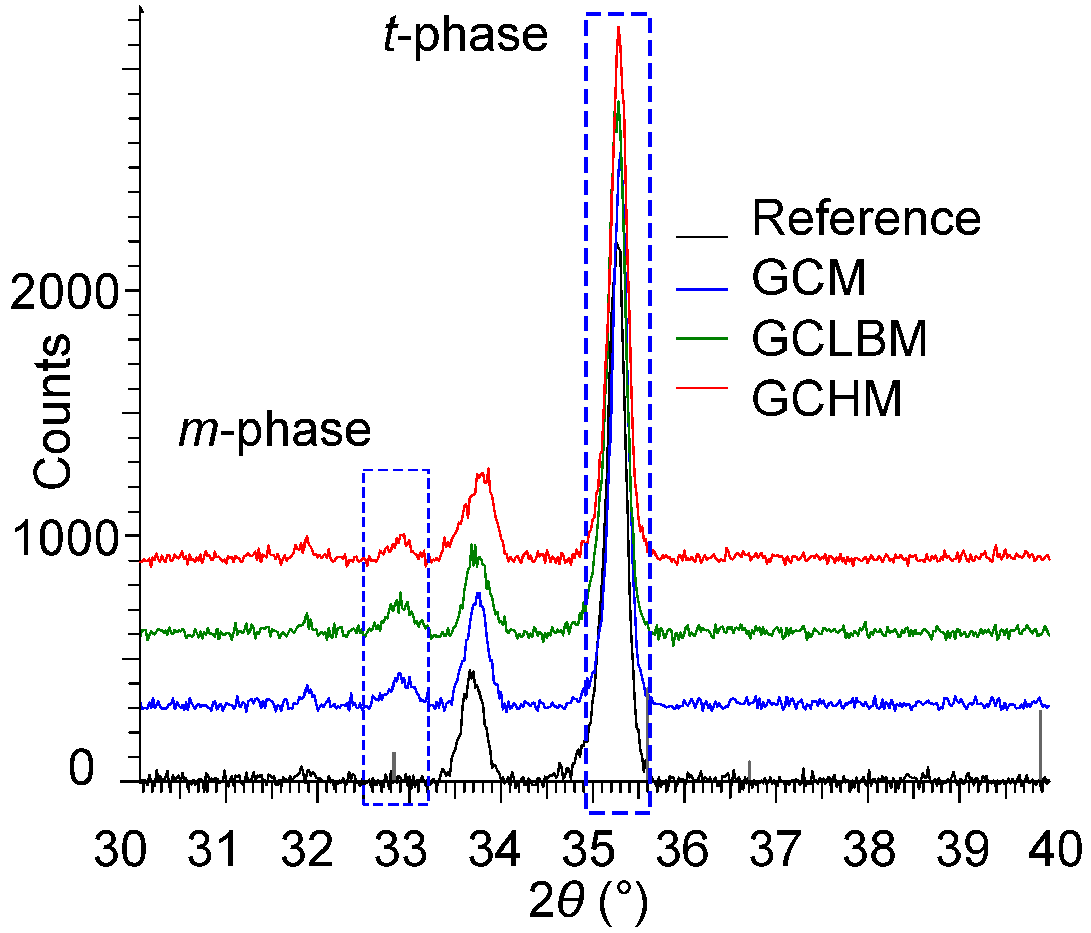
At the end of the sintering cycle, the percentage of tetragonal phase should be close to 100%. The shape of the curve is the same for the four processes on the diffractogram of Figure 3. The highest peak intensity at 2 θ angle of 35.2° is t-phase. As expected, the peak intensity of m-phase ( 2 θ 32.9°) is lower. An unidentified peak that could be due to the pigments or the DASIM (more likely as the peak probably belongs to a crystalline phase) added during the preparation of the powders, is noted between the two phases ( 2 θ 33.75°). It is identical for all processes and has, therefore, no influence on the comparison of mechanical properties.
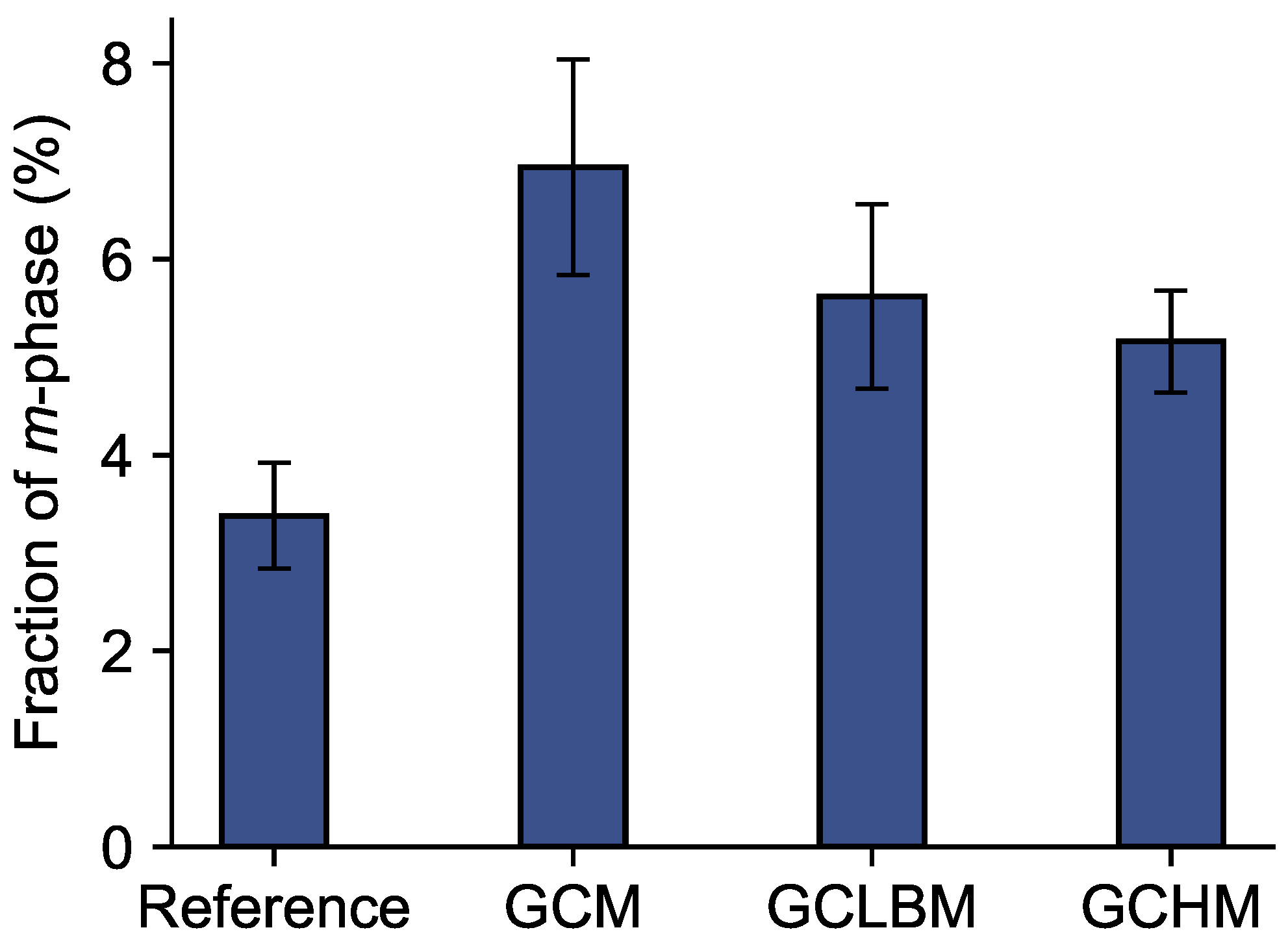
The fraction of m-phase calculated from peak intensity is shown in Figure 4. The reference process gives the best result, i.e., the lowest fraction of m-phase. For GCM, the percentage of m-phase is the highest at about 7%, compared to GCLBM and GCHM at about 5%. While a decreasing trend in the mean values of the percentage of m-phase is noted, the phase fractions are not significantly different for these three processes when the dispersion is considered (and this type of calculation is generally limited to qualitative analyses). The hybrid process exhibits the lowest dispersion. According to ISO 13356 [10], the four processes can be used to manufacture implants for surgery; m-phase fraction is lower than 20%.

3.3. Flexural Strength

Weibull diagrams (Figure 5) show that GCHM and GCM lines are almost parallel, but the characteristic strength is lower for the hybrid process. All k and σ 0 results (Table 3) are acceptable regardless of the manufacturing process. Indeed, Weibull moduli are at least equal to typical value (10) and flexural strengths are in the typical range (500–1800 MPa) of indicative values from commercial zirconia grades [2].
Parts obtained by GCM and GCLBM show a different mechanical behaviour; k is the highest for GCLBM, while σ 0 is the highest for GCM. The reference and the GCM process have very close characteristic strength values, while it is also for the GCLBM and hybrid process, but approximately 5% lower. GCLBM results in the highest Weibull modulus value, even higher than the reference. It means that confidence is high on its relative (by comparison to the other processes) low characteristic strength value. GCM exhibits the inverse behaviour, a larger dispersion for a higher characteristic strength. The hybrid process combines both characteristics with a large dispersion (i.e., a low k) and a slightly lower (by comparison to GCM) characteristic strength value.

4. Discussion

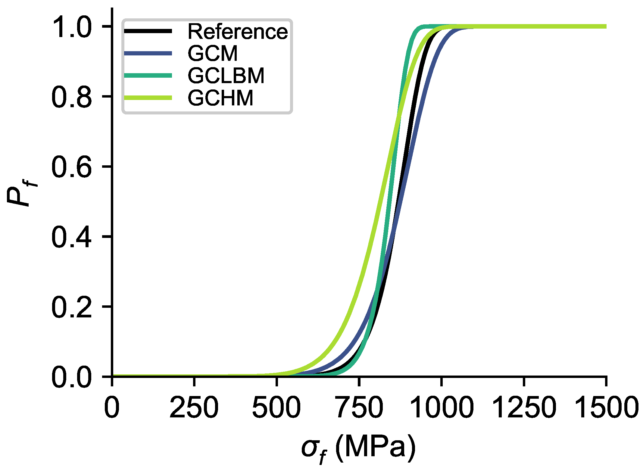
The probability of failure for each process (Figure 6) clearly shows that the distribution follows the same trend for GCM and GCHM, due to close Weibull moduli (11 and 10, respectively). The lower Weibull characteristic strength for GCHM shifts the distribution of about 50 MPa towards lower values.
Despite a low Weibull modulus, GCM is the process that ensures the closest flexural strength (905 MPa) to the reference (891 MPa). The low surface roughness of 0.45 μ m   R a with a low deviation (±0.08 μ m ) explains that the first failures appear at higher strength by comparison with GCHM (1.13 ± 0.10 μ m ). The total surface roughness value ( R t ), and especially its deviation (10.37 ± 3.86 μ m ), show that the distribution of surface defects is rather heterogeneous. This surface heterogeneity could be the result of micro-cracks apparition, which contributes to activate the t m toughening transformation. The occurrence of this transformation is confirmed by a significant presence of m-phase for GCM (the largest mean and dispersion values, 6.94 ± 1.10%, measured in this study, Figure 4).
Surface roughness values are very high for GCLBM ( R a = 2.37 ± 0.32 μ m and R t = 21.23 ± 4.92 μ m ) because the defects present on the surface before machining (the green blank is produced by uniaxial compaction) are intensified by the laser. In fact, the beam length varies locally during the interaction between the energy source and the material when the surface is not flat (beam length variations are linked to R t values of the surface being machined). The actual beam focus, as well as the surface locally machined by the laser, are therefore impacted, which influences material removal and surface topology. This leads to a non-uniform material removal rate. The phenomenon is amplified at each additional layer that is machined, leading to an increasing deviation from the target depth and of the surface roughness. The quality of the surface generated by GCLBM is therefore highly dependent on the initial surface state. The transformation toughening is less activated than for GCM due to the absence of tool contact that decreases the probability to generate micro-cracks, which explains why GCLBM has the highest Weibull modulus.
The proposed hybrid process has a positive impact on both the quality and the repeatability of the surface by comparison to GCLBM (surface roughness values and deviations are reduced from R a = 2.37 ± 0.32 μ m to R a = 1.13 ± 0.10 μ m and from R t = 21.23 ± 4.92 μ m to R t = 9.69 ± 0.94 μ m ), while enabling the possibility to machine small features thanks to the laser interaction. This shows the importance of the characteristics of the surface that will be machined with the laser beam. Milling that surface at the previous step is therefore important. Although the fraction of m-phase (Y-TZP destabilisation) and its dispersion are reduced with the laser step (from 6.94 ± 1.10% to 5.16 ± 0.52%), the level of the reference is not reached (3.38 ± 0.54%). The flexural strength value of GCHM and its reliability (845 MPa and 10, respectively) show that hybridisation globally results in a slight decrease in the mechanical properties. The flexural strength is slightly lower than for GCM (905 MPa) and the dispersion is higher than for GCLBM (20). This highlights that GCLBM influences negatively the characteristic strength obtained with GCM and that it does not allow improving its reliability.
In summary, the combination of two technologies rises the repeatability of the surface quality in terms of roughness or Y-TZP destabilisation, but the flexural strength is negatively impacted compared to the GCM process.

5. Conclusions

In this paper, Y-TZP ceramic samples are manufactured at the green stage by three different machining processes. One of them is the newly developed green ceramic hybrid machining (GCHM) process. It sequentially combines GCM and GCLBM to mainly increase productivity and obtain micro-features with no taper angle. The introduction of this new hybrid process at the green stage for the manufacturing of ceramic components that can be used in medical implants applications is the first contribution of this study.
After the sintering cycle, the samples are compared on different criteria such as the flexural strength, the surface quality and the Y-TZP destabilisation of the tetragonal phase component. This comparison shows that the hybrid process is a compromise and that it can even improve the results of GCM and GCLBM taken separately. Indeed, the repeatability of both the surface roughness and the Y-TZP destabilisation are improved (the dispersion around the mean values is reduced), as well as the values of the total surface roughness and the fraction of monoclinic phase. However, the flexural strength is not improved by comparison to GCLBM and its reliability is similar to that of GCM. Finally, the fraction of the monoclinic phase measured in the samples after sintering (less than 20%) makes GCHM (as well as GCM and GCLBM) suitable for manufacturing black Y-TZP surgery implants. The study and quantification of the impact of the finishing process on both the mechanical properties and the surface roughness of the final sintered ceramic component is another significant contribution of this study.
In addition, it is highlighted that the result of the previous manufacturing step is very important as the surface quality highly depends on it. If the quality of the component is critical for the application, we recommend carrying out a surfacing operation with a cutting tool (i.e., GCM) prior to GCLBM, corresponding to the sequence of the GCHM process introduced in this paper. It is consequently recommended to adopt GCHM to manufacture ceramic medical implants as phase stabilization and surface smoothing should significantly increase wear resistance of ceramic inserts.
Future work should include the study of the microstructure, residual stresses and micro-cracks on the machined surfaces, the identification of the second highest peak in the XRD diffractogram, but also the quantification of the contribution of each individual process of GCHM.

Author Contributions

Conceptualization: F.D., A.D., E.R.-L., F.P., C.D. and B.L.; methodology: F.D., E.R.-L., F.P., C.D. and B.L.; validation: F.D., A.D., E.R.-L., F.P. and C.D.; formal analysis: A.D., L.S., N.P. and M.M.; investigation: F.D., A.D., L.S. and N.P.; resources: F.D., E.R.-L., F.P., N.P., C.D. and M.M.; data curation: A.D.; writing—original draft preparation: F.D. and A.D.; writing—review and editing: F.D., A.D., E.R.-L., L.S. and B.L.; visualization: F.D. and A.D.; supervision: F.D., E.R.-L., F.P., C.D. and B.L.; project administration: F.D., E.R.-L., F.P. and C.D.; funding acquisition: F.P. and C.D. All authors have read and agreed to the published version of the manuscript.

Funding

This research received no external funding.

Data Availability Statement

The data presented in this study are available on request from the corresponding author.

Acknowledgments

The authors thank the Materials Science Lab of UMONS for the XRD measurements.

Conflicts of Interest

The authors declare no conflict of interest.

References

  1. Özel, T.; Biermann, D.; Enomoto, T.; Mativenga, P. Structured and Textured Cutting Tool Surfaces for Machining Applications. CIRP Ann. 2021, 70, 495–518. [Google Scholar] [CrossRef]
  2. Ferraris, E.; Vleugels, J.; Guo, Y.; Bourell, D.; Kruth, J.P.; Lauwers, B. Shaping of Engineering Ceramics by Electro, Chemical and Physical Processes. CIRP Ann. 2016, 65, 761–784. [Google Scholar] [CrossRef]
  3. Axinte, D.; Guo, Y.; Liao, Z.; Shih, A.J.; M’Saoubi, R.; Sugita, N. Machining of Biocompatible Materials—Recent Advances. CIRP Ann. 2019, 68, 629–652. [Google Scholar] [CrossRef]
  4. Kuebler, J.; Blugan, G. Failure Analysis of Zirconia Ceramic Watch Bracelet Components. Eng. Fail. Anal. 2011, 18, 625–632. [Google Scholar] [CrossRef]
  5. Bilal, A.; Jahan, M.P.; Talamona, D.; Perveen, A. Electro-Discharge Machining of Ceramics: A Review. Micromachines 2019, 10, 10. [Google Scholar] [CrossRef] [Green Version]
  6. Hannink, R.H.J.; Kelly, P.M.; Muddle, B.C. Transformation Toughening in Zirconia-Containing Ceramics. J. Am. Ceram. Soc. 2000, 83, 461–487. [Google Scholar] [CrossRef]
  7. Pereira, G.K.R.; Amaral, M.; Simoneti, R.; Rocha, G.C.; Cesar, P.F.; Valandro, L.F. Effect of Grinding with Diamond-Disc and -Bur on the Mechanical Behavior of a Y-TZP Ceramic. J. Mech. Behav. Biomed. Mater. 2014, 37, 133–140. [Google Scholar] [CrossRef]
  8. Ferrage, L.; Bertrand, G.; Lenormand, P.; Grossin, D.; Ben-Nissan, B. A Review of the Additive Manufacturing (3DP) of Bioceramics: Alumina, Zirconia (PSZ) and Hydroxyapatite. J. Aust. Ceram. Soc. 2017, 53, 11–20. [Google Scholar] [CrossRef] [Green Version]
  9. Liang, Y.; Dutta, S.P. Application Trend in Advanced Ceramic Technologies. Technovation 2001, 21, 61–65. [Google Scholar] [CrossRef]
  10. ISO 13356:2008; Implants for Surgery—Ceramic Materials Based on Yttria-Stabilized Tetragonal Zirconia (Y-TZP). International Organization for Standardization: Geneva, Switzerland, 2008.
  11. Demarbaix, A.; Mulliez, M.; Rivière-Lorphèvre, E.; Spitaels, L.; Duterte, C.; Preux, N.; Petit, F.; Ducobu, F. Green Ceramic Machining: Determination of the Recommended Feed Rate for Y-TZP Milling. J. Compos. Sci. 2021, 5, 231. [Google Scholar] [CrossRef]
  12. Cui, J.; Gong, Z.; Lv, M.; Rao, P. Determination of Fracture Toughness of Y-TZP Ceramics. Ceram. Int. 2017, 43, 16319–16322. [Google Scholar] [CrossRef]
  13. Song, J.Y.; Park, S.W.; Lee, K.; Yun, K.D.; Lim, H.P. Fracture Strength and Microstructure of Y-TZP Zirconia after Different Surface Treatments. J. Prosthet. Dent. 2013, 110, 274–280. [Google Scholar] [CrossRef]
  14. Zucuni, C.P.; Guilardi, L.F.; Fraga, S.; May, L.G.; Pereira, G.K.R.; Valandro, L.F. CAD/CAM Machining Vs Pre-Sintering in-Lab Fabrication Techniques of Y-TZP Ceramic Specimens: Effects on Their Mechanical Fatigue Behavior. J. Mech. Behav. Biomed. Mater. 2017, 71, 201–208. [Google Scholar] [CrossRef] [PubMed]
  15. Demarbaix, A.; Rivière-Lorphèvre, E.; Ducobu, F.; Filippi, E.; Petit, F.; Preux, N. Behaviour of Pre-Sintered Y-TZP during Machining Operations: Determination of Recommended Cutting Parameters. J. Manuf. Process. 2018, 32, 85–92. [Google Scholar] [CrossRef]
  16. Jarosz, K.; Ukar, E.; Krödel, A.; Özel, T. Laser Ablation and Processing of Polycrystalline Cubic Boron Nitride Cutting Tool Material. Int. J. Adv. Manuf. Technol. 2022, 118, 785–800. [Google Scholar] [CrossRef]
  17. Roitero, E.; Lasserre, F.; Roa, J.J.; Anglada, M.; Mücklich, F.; Jiménez-Piqué, E. Nanosecond-Laser Patterning of 3Y-TZP: Damage and Microstructural Changes. J. Eur. Ceram. Soc. 2017, 37, 4876–4887. [Google Scholar] [CrossRef]
  18. Yang, L.; Deng, Z.; He, B.; Özel, T. An Experimental Investigation on Laser Surface Texturing of AISI D2 Tool Steel Using Nanosecond Fiber Laser. Lasers Manuf. Mater. Process. 2021, 8, 140–156. [Google Scholar] [CrossRef]
  19. Samant, A.N.; Dahotre, N.B. Laser Machining of Structural Ceramics—A Review. J. Eur. Ceram. Soc. 2009, 29, 969–993. [Google Scholar] [CrossRef]
  20. Petit, F.; Lardot, V.; Ott, C.; Juste, E.; Cambier, F. Ceramic Particle Mixture, and Method for Manufacturing Ceramic Parts from Such a Mixture. U.S. Patent US9115034, 25 August 2015. [Google Scholar]
  21. Carter, C.B.; Norton, M.G. Ceramic Materials: Science and Engineering, 2nd ed.; Springer: New York, NY, USA, 2013. [Google Scholar] [CrossRef]
  22. Demarbaix, A.; Ducobu, F.; Preux, N.; Petit, F.; Rivière-Lorphèvre, E. Green Ceramic Machining: Influence of the Cutting Speed and the Binder Percentage on the Y-TZP Behavior. J. Manuf. Mater. Process. 2020, 4, 50. [Google Scholar] [CrossRef]
  23. Ducobu, F.; Rivière-Lorphèvre, E.; Demarbaix, A.; Lauwers, B. Prediction of Local Sintering in Laser Beam Machining of Green Y-TZP Ceramic. CIRP Ann.—Manuf. Technol. 2020, 69, 225–228. [Google Scholar] [CrossRef]
  24. Demarbaix, A.; Ducobu, F.; Juste, E.; Petit, F.; Duterte, C.; Rivière-Lorphèvre, E. Experimental Investigation on Green Ceramic Machining with Nanosecond Laser Source. J. Manuf. Process. 2021, 61, 245–253. [Google Scholar] [CrossRef]
  25. Xia, H.; Zhao, G.; Mao, P.; Hao, X.; Li, L.; He, N. Improved Machinability of TiB2–TiC Ceramic Composites via Laser-Induced Oxidation Assisted Micro-Milling. Ceram. Int. 2021, 47, 11514–11525. [Google Scholar] [CrossRef]
  26. Hao, X.; Xu, W.; Chen, M.; Wang, C.; Han, J.; Li, L.; He, N. Laser Hybridizing with Micro-Milling for Fabrication of High Aspect Ratio Micro-Groove on Oxygen-Free Copper. Precis. Eng. 2021, 70, 15–25. [Google Scholar] [CrossRef]
  27. Demarbaix, A.; Ducobu, F.; Preux, N.; Petit, F.; Rivière-Lorphèvre, E. Binder Influence on Green Ceramic Machining by Means of Milling and Laser Machining. Procedia CIRP 2021, 101, 206–209. [Google Scholar] [CrossRef]
  28. EN 843-1; Advanced Technical Ceramics—Mechanical Properties of Monolithic Ceramics at Room Temperature—Part 1 Determination of Flexural Strength. European Comittee for Standardization: Brussels, Belgium, 2004.
  29. EN 843-5; Advanced Technical Ceramics—Mechanical Properties of Monolithic Ceramics at Room Temperature—Part 5: Statistical Analysis. European Comittee for Standardization: Brussels, Belgium, 2006.
  30. Pereira, G.K.R.; Fraga, S.; Montagner, A.F.; Soares, F.Z.M.; Kleverlaan, C.J.; Valandro, L.F. The Effect of Grinding on the Mechanical Behavior of Y-TZP Ceramics: A Systematic Review and Meta-Analyses. J. Mech. Behav. Biomed. Mater. 2016, 63, 417–442. [Google Scholar] [CrossRef]
  31. Lughi, V.; Sergo, V. Low Temperature Degradation -Aging- of Zirconia: A Critical Review of the Relevant Aspects in Dentistry. Dent. Mater. 2010, 26, 807–820. [Google Scholar] [CrossRef]
  32. ISO 4288:1996; Geometrical Product Specifications (GPS)—Surface Texture: Profile Method—Rules and Procedures for the Assessment of Surface Texture. International Organization for Standardization: Geneva, Switzerland, 1996.
  33. Ono, K. A Simple Estimation Method of Weibull Modulus and Verification with Strength Data. Appl. Sci. 2019, 9, 1575. [Google Scholar] [CrossRef] [Green Version]
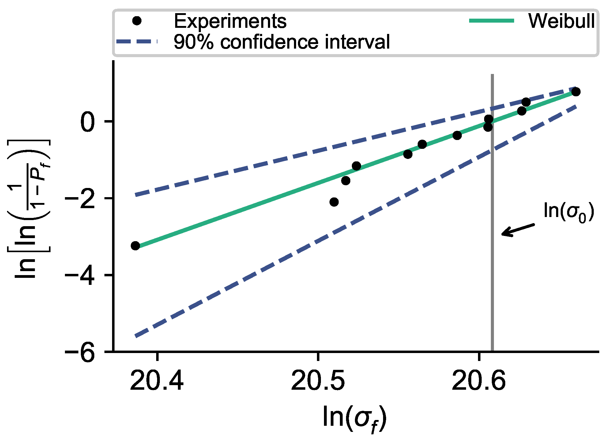
Figure 1. Weibull diagram for the reference process with a 90% confidence interval.
Jmmp 07 00118 g001
Figure 2. Surface roughness values for the three processes and the reference (error bars represent measurement uncertainty).
Jmmp 07 00118 g002
Figure 3. XRD diffractogram of the three processes and the reference.
Jmmp 07 00118 g003
Figure 4. Fraction of m-phase for the three processes and the reference (error bars represent measurement uncertainty).
Jmmp 07 00118 g004
Figure 5. Weibull diagram for the three processes and the reference.
Jmmp 07 00118 g005
Figure 6. Probability of failure for the three processes and the reference.
Jmmp 07 00118 g006
Table 1. Dimensions and tolerances of sample—Size B according to EN 843 [28].
Surface ConditionParameterLength (mm)Width, b (mm)Thickness, h (mm)
AllDimensional range≥454.0 ± 0.23.0 ± 0.2
MachinedParallelism tolerance±0.02±0.02
As-firedParallelism tolerance±0.10±0.10
Table 2. Machining parameters of black Y-TZP at the green stage.
GCM [22]GCLBM [23]
Depth of cut (mm)0.70.027
Feed rate /Scan speed (mm/min)135030,000
Tool/Beam diameter (mm)30.05
Cutting speed (m/min)133
Material removal rate (mm3/min)283540.5
Repetition rate (kHz)78
Power (%)85
Table 3. Weibull parameters of black Y-TZP for the three processes and the reference.
Processk σ 0 (MPa)
Reference15891
GCM11905
GCLBM20858
GCHM10845
Disclaimer/Publisher’s Note: The statements, opinions and data contained in all publications are solely those of the individual author(s) and contributor(s) and not of MDPI and/or the editor(s). MDPI and/or the editor(s) disclaim responsibility for any injury to people or property resulting from any ideas, methods, instructions or products referred to in the content.