1. Introduction
Ecological, economic, and social demands are leading to a change in the development, design, and production of future vehicles. In this context, many manufacturers’ stated goals are to advance the development of an environmentally friendly vehicle and climate-neutral production throughout the entire supply chain.
In common concepts, the energy storage units of these vehicles, which mainly consist of lithium-ion cells, are integrated within a battery housing in the underbody area of the vehicle structure [
1]. In addition to high demands on the corrosion resistance of the enclosures, crash safety, tightness of the components, and efficient utilization of the installation space are key requirements. Above all, the high crash safety requirements can be addressed by selecting high-strength steel grades for steel battery housing concepts. In order to meet these requirements with an all-steel battery enclosure, the joining processes must be adapted and optimized to meet these requirements. The aim of this study is to design laser beam welding and resistance spot weld bonding (RSW bonding) for joining high-strength steels, with emphasis on the leak tightness of the seams.
Depending on the design of the battery housing, there are high leak tightness requirements at the joints. Resistance spot welding in combination with adhesive bonding is an established, economical joining process. The so far unexplored leak tightness properties of this hybrid joining method are to be investigated for use in battery housings. The decisive advantage of this joining technique is the immediate load-bearing capacity of the joint after joining, in contrast to elementally bonded joints.
There is no need for a time-consuming fixation until curing, and cycle times can thus be significantly reduced. The additional use of structural adhesives in spot welding not only leads to a stiffness increase in the joint of about 30% [
2], but also increases the forces under oscillating loads by a factor of two to six [
3]. Even under shear loading, the hybrid specimens tested exhibit higher strength despite the potential adhesive contamination of the weld nuggets [
4]. The requirements of car body construction for the joint quality of resistance spot welds must be optimized by adjusting the welding parameters, such as the current intensity, electrode force, and welding time, to the joining task due to the significantly increased contact resistance between the joining partners [
5]. According to [
6], the variation of the adhesive layer thickness only has a minor influence on the quality of the weld spot.
In addition to improving the performance of the joint, the adhesive acts as a sealant for the joint gap, thus expanding the range of applications in sheet metal structures [
7]. However, since there can be an increased formation of weld spatter during RSW bonding and this can potentially lead to leakage, special attention should be paid to the stability of the process area [
8].
This joining technique thus has the potential to produce a joint that meets the requirements of the battery housing for electric vehicles. Due to the widespread use in high-volume production, production facilities as well as the know-how and confidence in this technique are available, allowing a timely and cost-efficient realization of resistance spot-welded steel battery housings. However, no systematic studies on the gas tightness of RSW-bonded high-strength steels have been published in the literature to date, so there is a need for research in this area.
Dual-phase (DP) steels consist of a ferritic and martensitic microstructure with typical grain sizes from 1 µm to 4 µm [
9]. The literature on laser beam welding of DP steels focuses on the mechanical behavior and microstructural changes caused by the process. A general overview of the problems of ultra-high-strength steels is given by Kah et al. [
10]. They show that the challenges in joining such steels lie mainly in their susceptibility to cracking and softening of the heat-affected zone. Kah et al. conclude that joining by means of laser beam welding, among others, is very possible, but that the quality of the weld depends on the optimal process design. Zhao et al. [
11] reported on DP600, DP800, DP 1000, and MS 1500 steel sheets overlap welded by a laser. They found that a reduced welding speed resulted in a large degree of martensite formation and a high degree of softening, and that the welding speed directly affected the degree of softening. Alves et al. [
12] and Sisodia et al. [
13] have studied the behavior of similar joints, and Di et al. [
14] studied dissimilar joints (DP780-DP980). The investigation of weldability by laser beam welding of dual-phase steels has so far tended to focus on lower DP steels (up to DP1000). This is due to the fact that dual-phase steels, which are frequently used as materials for car body parts, have so far mostly been joined by means of resistance spot welding. In the application of a steel battery housing, however, laser beam welding is particularly suitable due to its high energy density in a small welding area as well as accessibility from one side. Especially with regard to the requirements of gas tightness and dimensional stability, the process has high potential.
To consider the tightness of a laser weld, the influence of the zinc coating on the weld quality should be taken into account. The difference between the evaporation temperature of zinc (906 °C) and the melting temperature of steel (about 1530 °C) leads to spontaneous outgassing of the zinc and thus to blowholes, spatter, and a lack of fusion and resulting weld defects [
15]. These defects can be reduced by setting a gap between the joining partners. Particularly when this inter-sheet gap is too small, the above-mentioned defects occur. If the gap is too large, a “false friend” may result due to a lack of fusion of the upper and lower sheets [
15].
Investigations into gas-tight laser beam welding are known in the fields of aerospace [
16] and battery technology [
17]. For example, a hermetic seal is required for lithium-ion cell casings and they are laser-welded with uncoated materials such as aluminum and stainless steel [
17]. While unfavorable process parameters can lead to defects such as cracks and pores in aluminum casings [
18], which affect the tightness, gas-tight sealing of 316 L casings can be easily achieved [
16]. Equivalent studies on laser welding of zinc-coated steel sheets made of high-strength steel grades could not be found in the literature. Although steel can generally be effectively welded with a laser, restrictions are to be expected with regard to the gas-tightness of the seams in combination with a zinc coating. The feasibility of such joints is examined in this article.
2. Materials and Methods
Two high-strength steel grades were selected for the test specimens. The dual-phase steel DP-K®780Y1180T GI, referred to as DP1200 in the following text, has a tensile strength of 1180 MPa with an elongation at break of 10%. The surface is hot-dip galvanized with Z100. The second steel sheet used is CR440Y780T-DP, from now on referred to as DP780, with a tensile strength of 780–900 MPa and elongation at break of at least 14%. This sheet is also hot-dip galvanized, but in this case with Z140. Both materials are well suited to the requirements of modern automotive production in terms of weight optimization and safety and are characterized by good weldability.
2.1. Resistance Spot Weld Bonding
Two structural epoxy-based (EP) adhesive systems were selected for the experimental investigations. The first is a one-component EP (1C-EP) with a tensile strength of 31 MPa and 11% elongation at break, which is specially developed for the body shop. It is used to increase crash performance and the stiffness of the entire car body. It is compatible with mechanical and thermal joining techniques such as resistance spot welding. Due to its sealing capacity, it has a high durability and good corrosion protection. The curing takes place in an oven for 30 min at 180 °C.
The second adhesive is a two-component EP (2C-EP) with a tensile strength of 22 MPa and 3% elongation at break. This adhesive is developed for use in structural joints with high toughness and strength. It has high heat and environmental resistance and can also be used in hybrid joints, such as joints combined with resistance spot welding and riveting. The curing takes place for at least seven days at 23 °C, 50% r.H (see
Table 1).
2.2. Laser Welding
A 6 kW disk laser with a wavelength of 1030 nm is used for the laser-welded samples in cw mode. The welds are carried out as remote welds with remote welding optics model RLW-A from Scansonic MI GmbH and an imaging scale of 1:2.9 at a focal length of 500 mm with a fiber diameter of 200 µm. The optics are inclined 15 degrees laterally to the fillet weld and are stationary during welding. The specimen is pressed onto the specimen holder by an electromagnet underneath the specimen with a force of 960 N. The specimen holder is mounted on a rotary axis that rotates according to the set welding speed. The optics used are able to determine the exact position of the sheet edge of the upper sheet by means of leading laser lines and automatically align the position of the laser spot to it. Filler material is not used. Small metal sheets with the appropriate thickness are inserted between the top sheet and the bottom sheet for the exact adjustment of the joint gap and removed again after the welding process. A fixed set of parameters is used for the experiments: 5 KW laser power at 4.0 m/min welding speed and a laser spot size of 1.0 mm. The selected process parameters were determined in preliminary experiments for this material–thickness combination.
2.3. Test Specimens
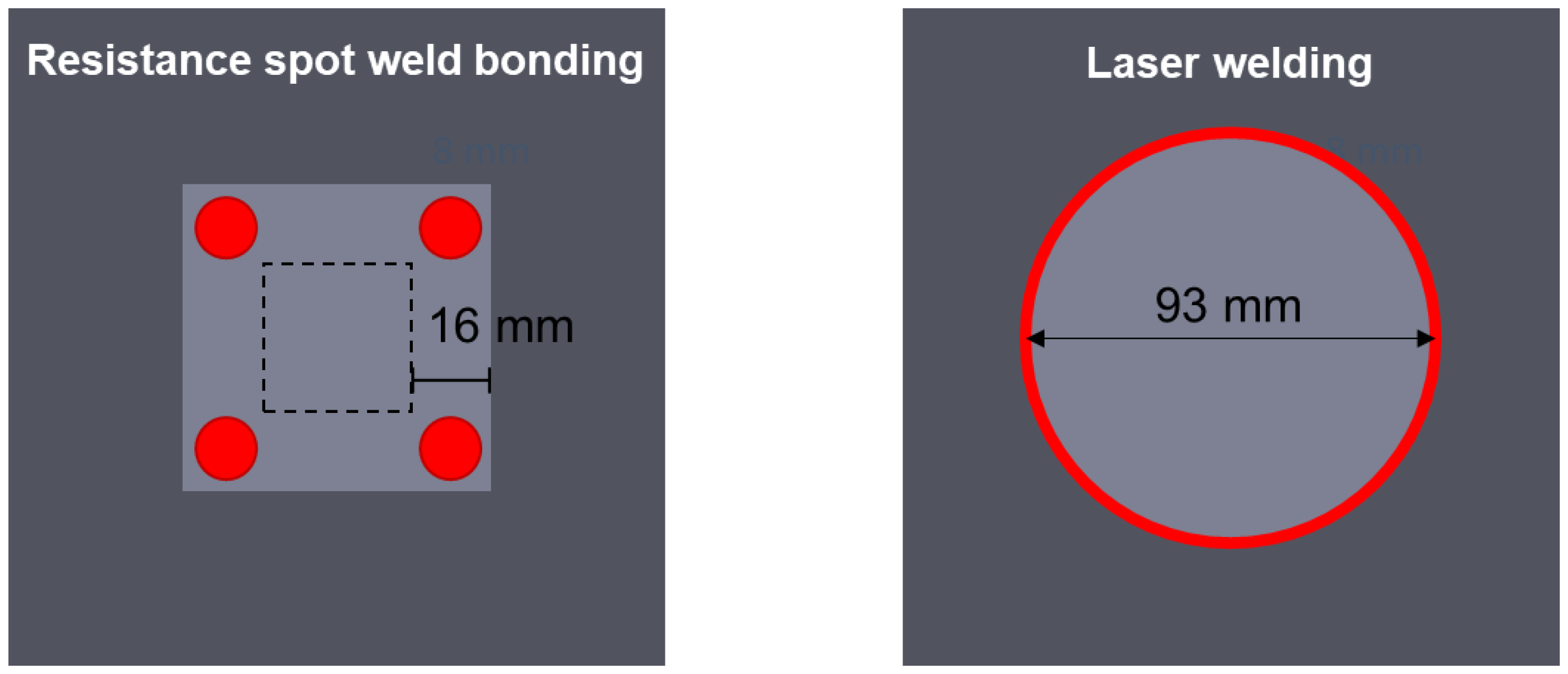
The experimental investigations focus on optimizing the joining process parameters of laser-welded joints and resistance spot-weld-bonded joints with regard to the leak tightness properties. For this purpose, test specimens of a geometry specially developed for this case are joined (see
Figure 1). First, a square base plate is cut to size and provided with a square cutout in the center. For resistance spot weld bonding, a cover plate with an overlap length of 16 mm is joined over this. After applying the adhesive and bringing the joining partners together, a resistance spot weld is performed in accordance with the manufacturer’s instructions before the adhesive cures.
To evaluate the leakage rate of the laser welding, a round cover plate is placed centrally on the base plate and circumferentially welded.
These test specimens can then be fixed in a fixture in which a defined test volume is pressed onto the base plate. In this way, leaks can be measured with the integral leak test and localized with the local leak test.
2.4. Leak Testing
Leak tightness is described as the flow rate of a fluid into or out of a test object [
19]. There are no perfectly leak-tight objects, as every object has at least minimal defects that can lead to leakage [
20]. For this reason, the task of leak tests is to check whether the measured leakage rate is below a defined limit value. If the leakage rate is below the defined limit leakage rate, the object is described as functionally tight. In general, a distinction can be made between integral and local leak testing. The integral leak test is performed to examine the overall leak tightness of the test object. The local leak test is used to find the location of a leak [
21]. Depending on the size of the leak, different effects can be used for leak detection. All methods rely on the change in a physical property that is measured on one side of the vessel while the pressure or gas type is changed on the other side. If the gas composition is changed on one side of the specimen, the extent to which the gas composition on the other side also changes is measured [
22].
In the experimental investigations of this study, the decay test with air is performed as an integral test method. For the local leak test, the helium sniffing leak detection is selected.
2.5. Pressure Difference Test
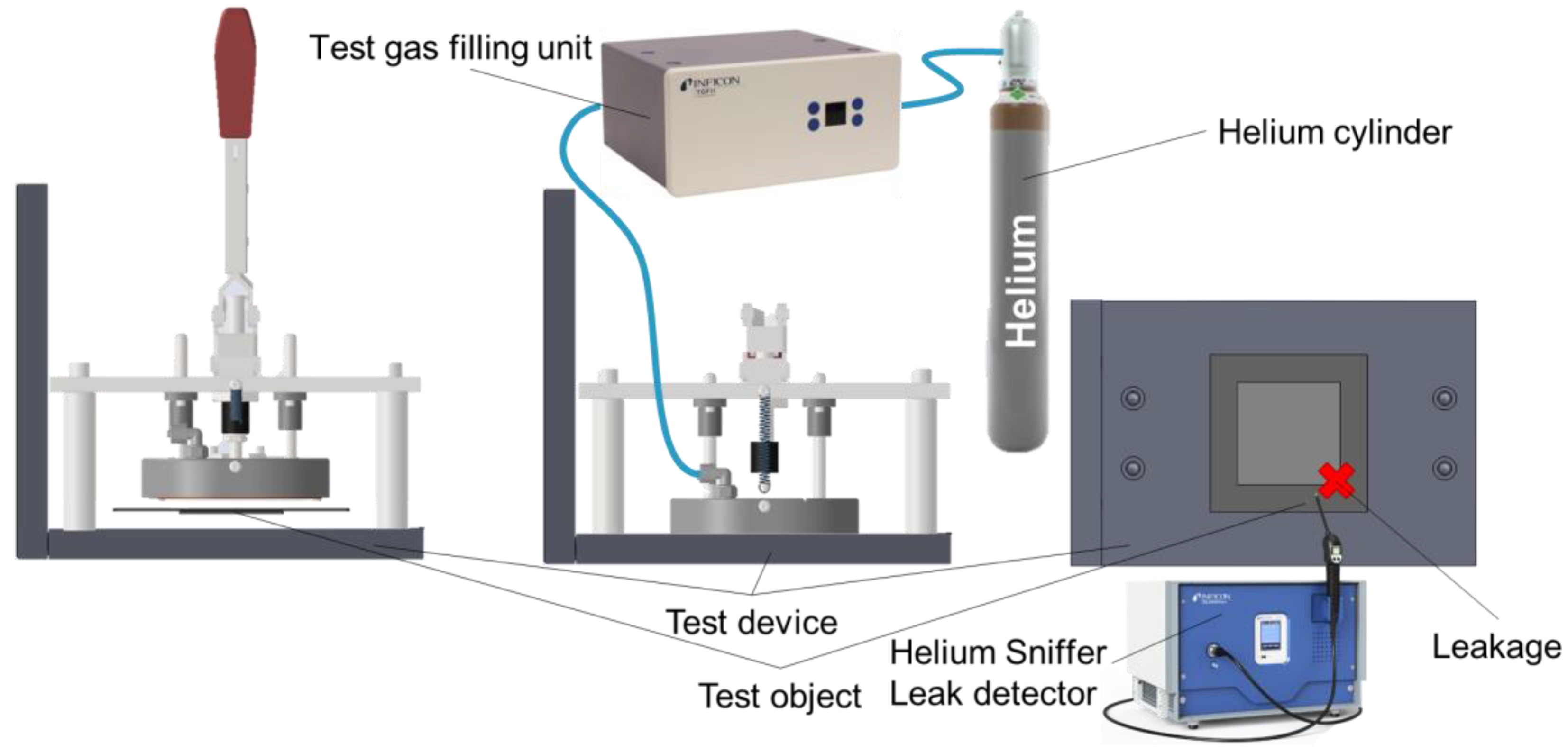
For the experimental integral leak tests within the scope of this work, the pressure difference test is selected. Air is used as the test gas. This test method can be performed in two ways. On the one hand, a negative pressure can be generated in the test volume and the pressure rise can be measured. Alternatively, a positive pressure can be applied to the test object and the pressure drop is evaluated. This method, known as the pressure drop method, is selected in this work because of its relatively simple handling and high process reliability. In this way, numerous factors influencing the joining processes on the sealing properties of the composite can be investigated with acceptable experimental effort.
The test sequence of the pressure decay method is shown in
Figure 2. It can be divided into four phases. In the first step, the test object is subjected to an overpressure of 100 mbar. Then, the valve of the leak tester is closed. Battery housings for electric vehicles must meet the leak tightness requirements of IP67, so the test pressure was selected based on this standard. For a test according to IP67, the test specimen is to be immersed in water under a water column of 1 m. The test pressure is to be selected based on this standard. The resulting overpressure is 100 mbar. [
23]. The subsequent stabilization phase serves to minimize measurement fluctuations. The leak test is performed in the third phase of the test sequence. The pressure change in the test volume is recorded over the test time. The leakage rate is calculated on the basis of these measured values. In the fourth phase, the valve is opened again to vent the test object [
24].
The leakage rate is calculated according to Equation (1). For this purpose, the measured pressure change is multiplied by the internal volume of the test assembly and divided by the measurement time [
20]. This results in the unit mbar×l/s for the leakage rate.
Equation (1): Leakage rate calculation [
20]
In order to avoid negative effects of temperature fluctuations during the measurement, the tests are carried out in an air-conditioned room at 23 °C and 50% r.h. Under these conditions with constant atmospheric pressure during the measurement period, it is possible to simplify the unit into mL/min. The conversion to this unit, which is frequently used in practice, is carried out according to Equation (2).
Equation (2): Leakage rate calculation [
25]
The joints used in battery housings must prevent the ingress of water or water vapor. For this reason, the limit leakage rate for the developed test specimens is set at 10
−3 mbar×l/s or 0.06 mL/min [
26].
2.6. Helium Sniffer Leak Detection
In helium sniffer leak detection, the test object is filled with helium overpressure [
27],
Figure 3. The sniffer sensor is then guided along the joint seam to determine the local leakage rate [
28]. Due to the following properties, helium is ideally suited as a test gas. It is chemically and physically inert, non-explosive, and has a low content in the ambient air so that it provides a clear signal in the mass spectrometer [
22]. Because it has a small collision cross-section, helium can flow well through narrow channels, allowing very small leaks to be detected. The test object is filled with helium for only a short time. Since helium is a noble gas, adhesives are not affected by the test gas and the behavior is therefore not changed. During the test, it is important that the test room is sufficiently ventilated to avoid contamination of the test environment by the test gas. This would lead to an increase in the helium concentration in the ambient air and thus to a reduction in the measurement sensitivity [
29]. Leakage rates of up to 10
−6 mbar×l/s can be detected with this test method, well above the permissible leakage rate for the required leak tightness, which is 10
−3 mbar×l/s [
30].
2.7. Leakage Test Procedure for Evaluating the Leakage Rate of Joined Steel Test Specimens
Figure 4 shows the leakage test sequence for evaluating the leakage rate on joined steel test specimens. In the first step, the integral leak test is carried out. If the integral leakage rate is higher than the defined limit of 0.06 mL/min, this test specimen does not meet the leak tightness requirements and is declared to be untight. The leakage is then localized on these test specimens using a leak detection spray in order to evaluate and analyze the locations of the leaks. If the leakage rate falls below the limit, the next step is the local leakage test with the helium sniffing leak detection. If the local limit leakage rate of 10
−3 mbar×l/s is exceeded at one point of the joint seam, this test specimen is also declared to be untight, and the localized leakage can be analyzed. If the test specimen also reliably falls below the local limit leakage rate at each point, the test specimen and thus the tested joint are declared to be tight.
3. Results
3.1. Resistance Spot Weld Bonding
The basis of the investigations of the leak tightness properties of resistance spot-weld-bonded joints is the parameter optimization of the resistance spot welding process on the basis of the Testing and Documentation Guideline for the Joinability of thin sheet of steel—Part 2: Resistance Spot Welding [
31]. This is a public guideline. The chisel test is used to determine the welding range. For this purpose, two pieces of sheet metal of the respective joining partners with dimensions of 45 mm × 45 mm with a 40 mm overlap are centrally joined by a spot weld. The parameter determination starts with a welding current of 3.0 kA. Two specimens are welded for each current setting. The welding current is successively increased by 0.2 kA until the minimum spot diameter is reached for the first time. This is calculated with the formula dw
min ≥ 4√t, where t stands for the plate thickness of the thinnest joining partner. The minimum welding current Imin is then determined by varying the welding current in 0.1 kA steps until dwmin is reached in five successive welds. The maximum welding current (I
max) is defined by the spatter limit. This is reached when spatter occurs between the sheets in two successive welds with the same welding current. The welding current is then reduced in 0.1 kA steps until at least three consecutive specimens can be joined without spatter [
31].
The DP1200 material has a thickness of 1.45 mm, and the DP780 plate has a thickness of 1.2 mm. For the DP780-DP1200 material combination, this results in a minimum spot weld diameter of 4.38 mm. The optimally determined ideal parameters are an electrode force of 4.5 kN at a welding amperage of 7.1 kA. The welding time is 380 ms, with pre- and post-weld times of 300 ms each.
With these optimized process parameters, test specimens are then joined with a one-component and a two-component epoxy resin adhesive. For this purpose, the adhesives are first applied automatically to the base sheet. The cover plate is then joined, and four spot welds are made at the corner points at intervals of 50 mm. The adhesives are then cured according to the manufacturer’s instructions.
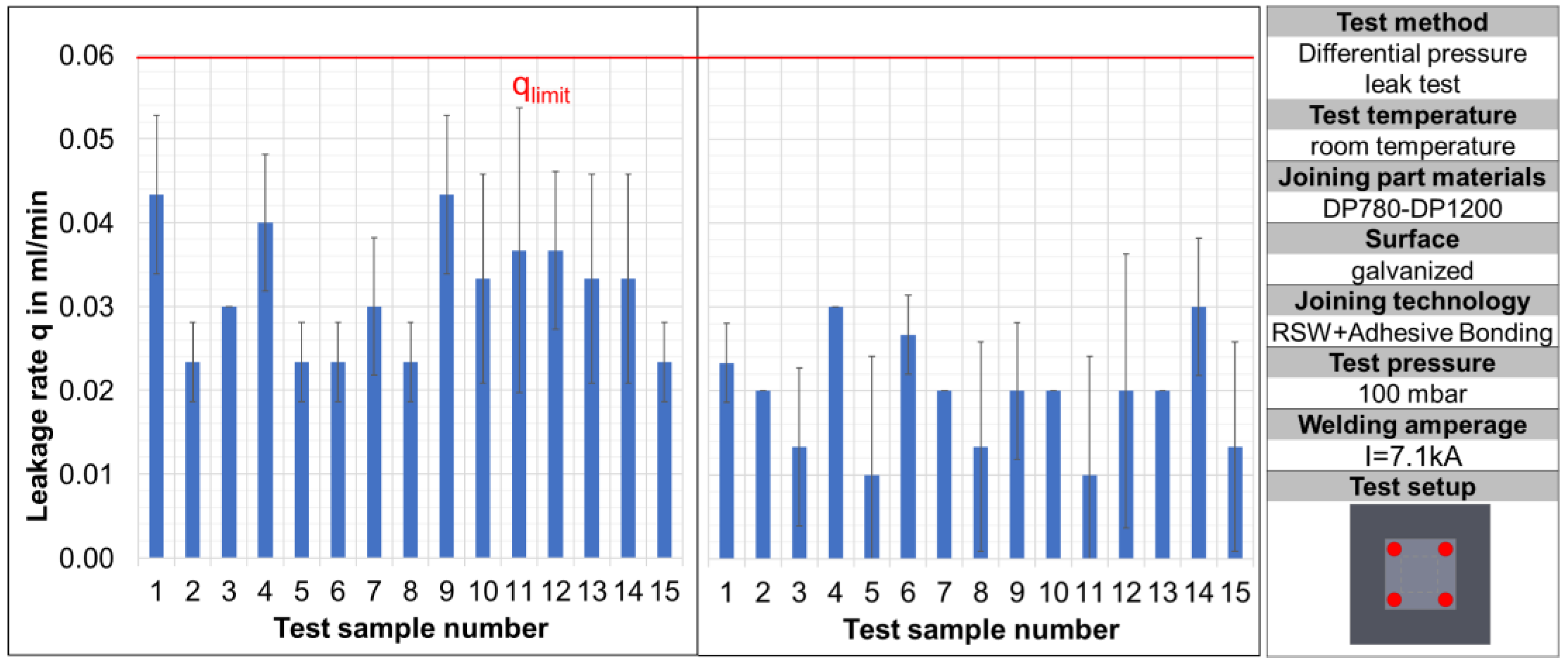
These test specimens are then leak-tested. The results of the integral leak test of the test specimens joined with optimum joining process parameters can be seen in
Figure 5. It is obvious that the leakage rates when using both adhesive systems are in the range between 0.01 mL/min and 0.04 mL/min and are thus well below the defined integral limit leakage rate. For this reason, the test specimens will be tested with the helium sniffer for leak detection in the next step.
The results of the local leakage test are summarized in
Figure 6 for both adhesive systems used. During the test, eight measuring points are defined along the joint. One in each corner area, and one on each of the sides in between. In the area of these measuring points, the maximum measured local leakage rate is documented.
Since the consistently tight specimens showed only very small deviations within the eight measuring points, the local leakage rates are given in the figure for each specimen as the mean value of the eight measuring points. The local leakage rates are in the range of 5 × 10⁻⁶ to 10−5 mbar×l/s at the optimum process parameters. This is two orders of magnitude below the defined limit leakage rate, so that the functional tightness of all joined specimens is fulfilled for the application in battery housings for electric vehicles. This confirms the results of the integral leakage test.
Because it is not possible to guarantee compliance with the optimum process parameters in the series production process without deviations, the influences of various process parameters on the leakage rates for both adhesive systems are investigated below.
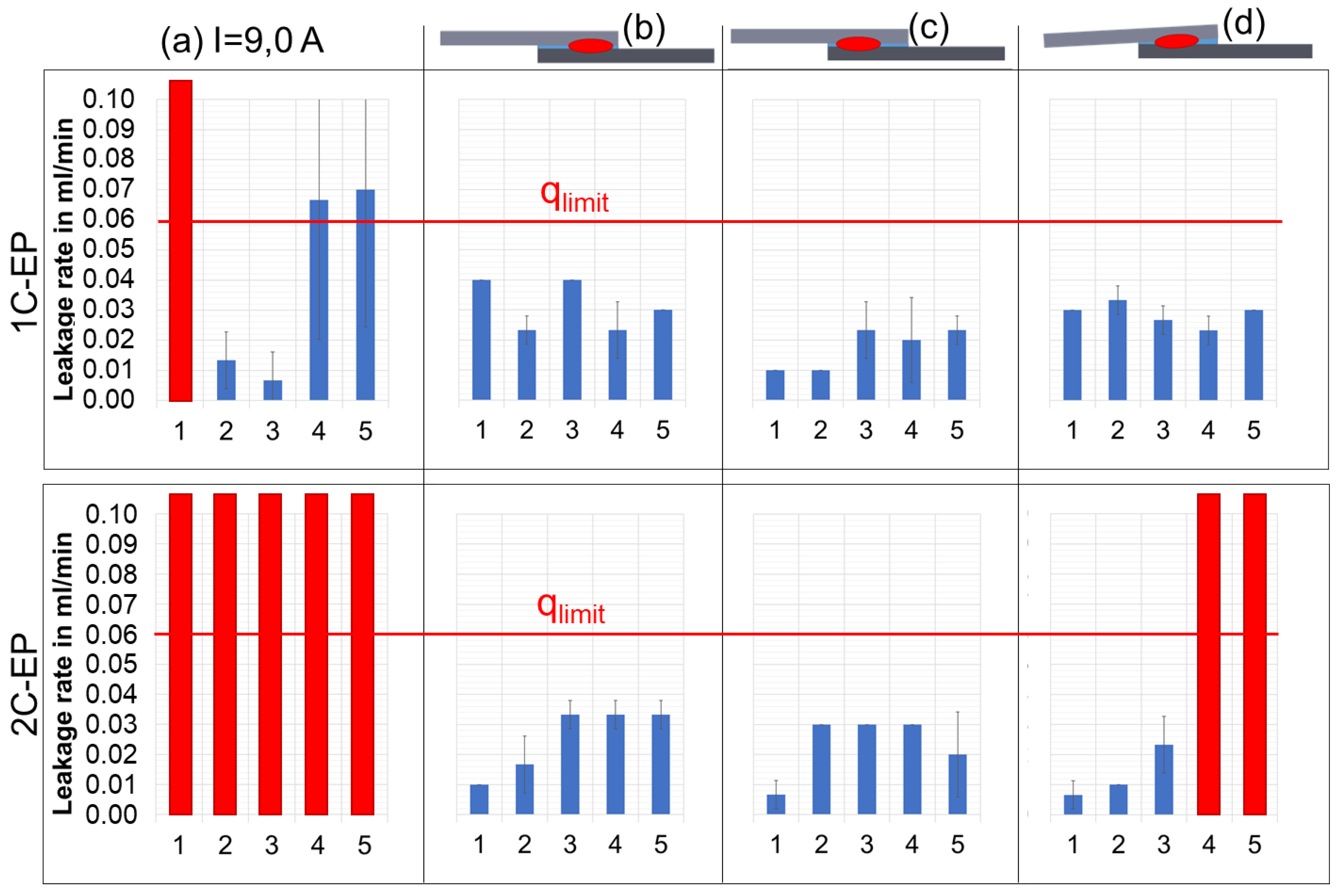
For this purpose, the welding current is first increased to 9 kA. This value is chosen as an example and is clearly outside the welding range to provoke the weld spatter that should ideally be avoided.
As can be seen in
Figure 7a, the weld spatter resulting from the increase in the welding current leads, in all cases, to heavy leakage when using the two-component adhesive. Heavy leakage in the integral leakage test means that the applied test pressure already drops during the stabilization time, so that a leakage rate can no longer be calculated. The weld spatter therefore leads to defects in the adhesive layer, resulting in leakage channels that lead to an untight joint. When joining with the one-component adhesive, one of the five specimens also exhibits heavy leakage; two specimens fail the leak tightness requirements; and the two remaining specimens exhibit leakage rates slightly above the limit leakage rate.
With these results, however, it should be noted that a significant overshoot of the welding current in the series process can be easily detected and thus avoided by process monitoring, so that this error pattern can be quickly eliminated in the series process.
However, there are process errors that process monitoring cannot easily detect. These include mispositioning of the welding points or an increased gap between the joining partners, which can occur, for example, due to manufacturing tolerances of the joining parts. For this reason, weld spot positioning outside the center of the overlap was also analyzed (
Figure 7b,c). Likewise, one corner of the cover plate was drilled out by 2 mm in order to map an increased joining gap during resistance spot weld bonding and be able to investigate it with regard to the leakage rates.
As can be seen in
Figure 7b,c, off-center positioning of the spot welds in the hybrid joining process has no negative effect on the leakage rate. For both the 1C EP and the 2C EP, the integral leakage rates remain in a range from 0.01 mL/min to 0.04 mL/min, which is comparable to the test specimens with centrally positioned spot welds.
The gap formation between the joining partners (
Figure 7d) also has no negative effects on the leakage rate of the 1C EP, so that functionally tight joints could be produced here, despite a bending up of 2 mm. With 2C-EP, three out of the five test specimens are also tight with leakage rates of 0.01–0.02 mL/min. Two test specimens, however, show heavy leakage and therefore do not meet the leak tightness requirements.
3.2. Laser Welding
A total of 69 samples were analyzed for this study.
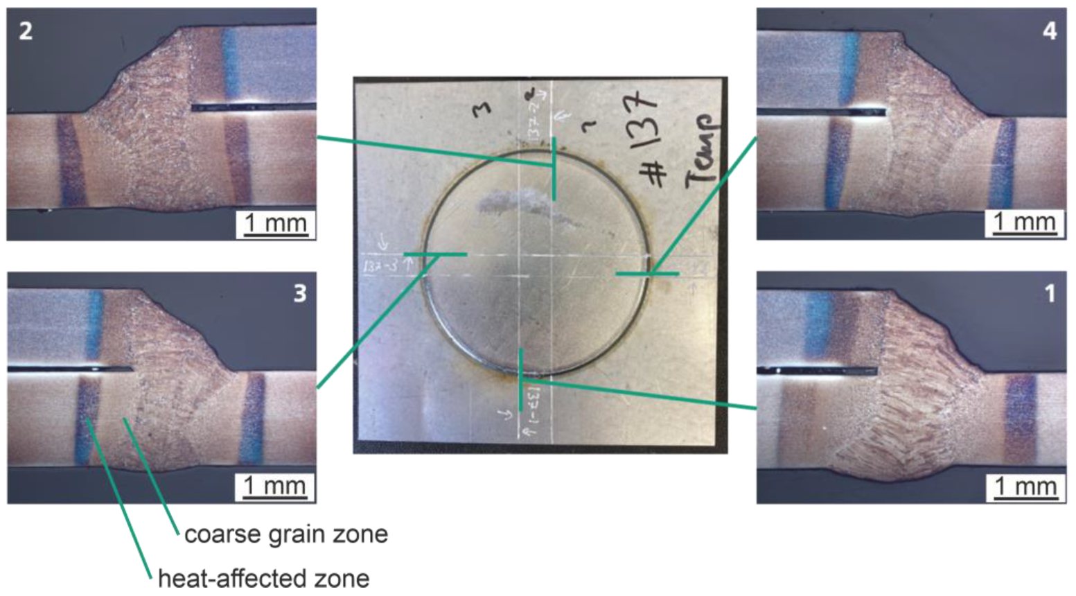
Figure 8 shows a top view and four cross-sections of a representative sample. The sample shown is welded with a weld gap of 0.1 mm. The seam forms evenly and smoothly on the surface. Almost no weld spatter can be seen on the specimen itself. Outer welding defects are not visible. A cross-section is taken from each side. Cross-section number one corresponds to the start and end area of the seam where the seam is closed. As with the other cross-sections, there are no defects such as pores or cracks. The base material is completely penetrated at the set angle of 15 degrees, and the gap is completely bridged. In cross-section number four, and thus 1/4 after the starting point, a seam incidence is visible at the upper edge of the top sheet. The heat-affected zone and coarse grain zone are visible due to the two-percent etching using Nital. The width of the heat-affected zone is about 500 µm for each joining partner, measured at the center of each sheet.
Figure 9 shows a hardness mapping by HV0.1 (macroscopic hardness test according to DIN EN ISO 6507-1) of cross-section number two from
Figure 8. In general, the hardness of the base materials used varies between about 200 HV0.1 for the top sheet (DP780) and about 450 HV0.1 for the bottom sheet (DP1200). In the area of the heat-affected zone in the lower sheet, a drop in hardness can be seen in a range of approx. 1 mm, in which the hardness declines to as low as 240 HV0.1. In the coarse grain zone of the bottom sheet, an area of hardening with values between 515 HV0.1 and 585 HV0.1 is visible. A hardness of 445 HV0.1 to 515 HV0.1 is recorded over the entire area of the weld. In the upper sheet, after the coarse grain zone, a narrow area with hardness values between 305 HV0.1 and 375 HV0.1 is visible, with a rapid transition to the hardness values of the base metal.
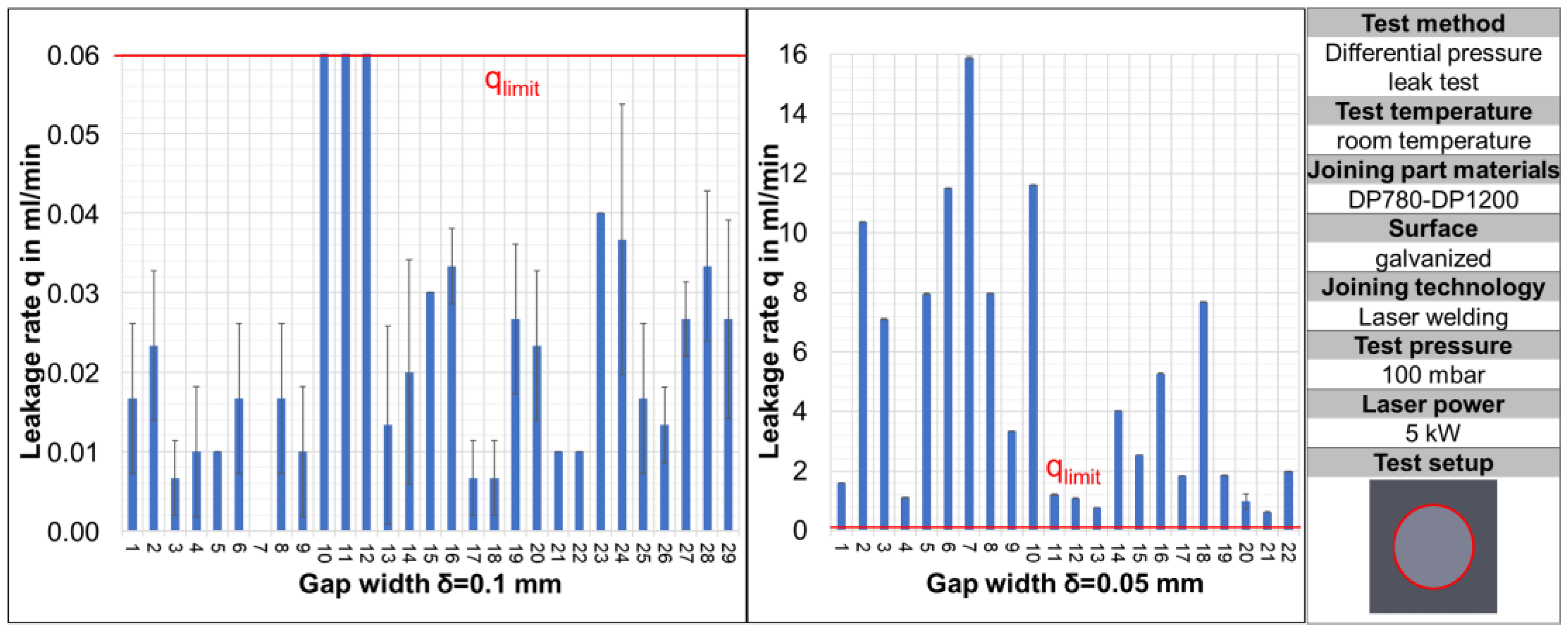
The leakage rate is documented in
Figure 10 as a function of the gap size set between the joining partners.
For a gap size of 0.05 mm, each of the samples is above the limiting leakage rate of 0.06 mL/min and thus leaking. For a gap size of 0.1 mm, 3 of the 29 samples exceed the limiting leakage rate.
4. Discussion
With optimum joining process parameters, gas-tight joints can be produced with resistance spot welding. The integral leakage rates can be confirmed by local leak testing. It is noticeable that the weld spatter in the cold-curing adhesive system leads to heavy leakages in all cases, whereas the hot-curing adhesive sometimes leads to tight bonds despite the weld spatter. A potential explanation for this is that the flaws in the adhesive remain unchanged in the 2C adhesive due to curing at room temperature.
Potential imperfections in the 1C adhesive can possibly be closed again by increasing the temperature during curing. The increase in temperature to 180 °C initially causes the viscosity of the adhesive to drop significantly, allowing it to flow into any imperfections that may occur, before the viscosity increases again as a result of the curing reaction.
Off-center spot weld positioning does not negatively affect the leakage rate for both adhesive systems. Positioning closer to one edge of the overlap creates a larger area of homogeneous adhesive layer on the opposite side, so that sealing can be ensured here.
The remote laser beam welds performed are free of defects on the surface as well as in the cross-sections taken. This is particularly true for the weld specimens with an inter-sheet gap of 0.1 mm (cf.
Figure 8). In detail, for the weld specimens with an inter-sheet gap of 0.05 mm, clear weld spatters and partial blowouts are visible on the upper side of all the specimens. Qualitatively, this observation of the seam appearance coincides with the general tightness of the samples (cf.
Figure 10). Nevertheless, the authors could not establish a qualitative correlation between the occurrence of spatter (frequency, intensity, or mass loss) and the occurrence of leakage (>0.06 mL/min) on the basis of individual samples. As shown in
Figure 10, only the general correlation over the number of several samples and its tendency behavior can be confirmed. The observation that with a smaller inter-sheet gap, welding irregularities such as weld spatter and blowouts become more frequent is consistent with studies in the literature; cf. [
15]. It is plausible that this in turn degrades the gas tightness. If the gap is too large, the zinc vapor can escape well, but a lack of fusion can arise, which in turn prevents gas tightness. In samples with an inter-sheet gap of 0.1 mm, significant leakage also occurs in isolated cases, even under otherwise constant conditions. Moreover, these outliers cannot be detected by visual inspection on the basis of the external appearance of the weld seam, i.e., even if no clear weld spatter or blowouts are visible, the weld may have a leak.
The hardness mapping shows a typical result for DP steels after laser remote welding: A softening zone forms along the HAZ, with a hardness drop of approx. 100 HV0.1 to 150 HV0.1. At the same time, there is a clear hardening in the fusion zone (FZ) of the weld. These observations are consistent with reports from the literature. Alves et al. [
12] also report a clear softening zone and hardening in the FZ during laser welding of DP1000. Residual austenite and the tempering of previous martensite are therefore responsible for the softening between intercritical and subcritical HAZ. The size and volume fraction of retained austenite increase from the FZ toward the HAZ. [
12] Sisodia et al. [
13] also investigate laser welding of DP800-DP800 and DP1200-DP1200 materials. They report a comparable softening zone, but the hardening of the FZ is not as pronounced as in this study. In
Figure 9, the hardening of the upper joining partner (DP780) is particularly pronounced, with more than a doubling of the hardness compared to the base material. This is in line with the study by Di et al. [
14], who investigated the laser welding of the dissimilar joining partners DP780-DP980, similar to the analysis in
Figure 9. Here, too, the softer joining partner (DP780) experiences a significantly higher increase in hardness in the FZ, which approaches the hardness of the DP980 FZ.


 ,
, 


