Article

Development and Practical Implementation of Digital Observer for Elastic Torque of Rolling Mill Electromechanical System

by
Vadim R. Gasiyarov
1,
Andrey A. Radionov
2,*,
Boris M. Loginov
3,
Alexander S. Karandaev
2,
Olga A. Gasiyarova
4 and
Vadim R. Khramshin
2
1
Department of Automation and Control, Moscow Polytechnic University, 38, Bolshaya Semyonovskaya Str., 107023 Moscow, Russia
2
Power Engineering and Automated Systems Institute, Nosov Magnitogorsk State Technical University, 38, Lenin Avenue, 455000 Magnitogorsk, Russia
3
Department of Mechatronics and Automation, South Ural State University, 454080 Chelyabinsk, Russia
4
Department of Material science, LLC NPP Uchtekh-Profi, 147, Kommuny Str., 454080 Chelyabinsk, Russia
*
Author to whom correspondence should be addressed.
J. Manuf. Mater. Process. 2023, 7(1), 41; https://doi.org/10.3390/jmmp7010041
Submission received: 13 November 2022 / Revised: 27 January 2023 / Accepted: 30 January 2023 / Published: 4 February 2023

Abstract

:
The strategic initiative aimed at building “digital metallurgy” implies the introduction of diagnostic monitoring systems to trace the technical condition of critical production units. This problem is relevant for rolling mills, which provide the output and determine the quality of products of metallurgical companies. Making up monitoring systems requires the development of digital shadows and coordinate observers, the direct measurement of which is either impossible or associated with numerous difficulties. These coordinates include the spindle torque applied by the spring-transmitting torque from the motor to the rolling stand rolls. The development and research are conducted by the example of the electromechanical systems of the horizontal stand at the plate mill 5000. The stand electric drive characteristics are given, and the emergency modes that cause mechanical equipment breakdowns are analyzed that. The relevance of analyzing transient torque processes in emergency modes has been accentuated. The paper points to the shortcomings of the system for elastic torque direct measurement, including low durability due to the harsh operating conditions of precision sensors. It also highlights the need to install the measuring equipment after each spindle. The disadvantage of the previously developed observer is the function of calculating the electric drive speed derivative. This causes a decrease in noise immunity and signal recovery accuracy. The contribution of this paper is building a digital elastic torque observer that has advantages over conventional technical solutions, based on the theoretical and experimental studies. The technique for virtual observer adjustment was developed and tested in the Matlab-Simulink software package. For the first time, a comprehensive analysis was conducted for spindle elastic torques in emergency modes that caused equipment damage. An algorithm was developed for an emergency shutdown of a stand electric drive in the worst-case mode of strip retraction between work and backup rolls, due to the overlap of the strip on the roll. Further, the algorithm was tested experimentally. The criteria for diagnosing pre-emergencies was then justified. An adaptive motor-braking rate controller was developed. The developed observer and emergency braking system are in operation at the mill 5000. Long experimental research proved the efficiency of dynamic load monitoring and the reduction in the number of equipment breakdowns.

1. Introduction

1.1. Digital Twin and Digital Shadow

Implementing the digital rolling mill concept requires equipping it with devices for the continuous monitoring of its technical condition [1,2]. They should form the basis of diagnostic monitoring systems, which will provide smart production and contribute to innovations in the metallurgical industry [3,4,5,6,7,8]. This concept involves new principles for monitoring the equipment state [9,10,11,12,13]. Its implementation requires developing a complex of digital models, twins, and shadows [14,15].
As is known, a digital twin (DT) implements a bidirectional online data exchange between the object and the virtual model. In digital shadows, state observers are characterized by a one-way data transfer from the object to the model [16,17,18]. According to the definition in [19], “a state observer is a model connected in parallel to the control object, continuously receiving data on the changes in the control action and the controlled parameter.
According to the authors of [20,21,22], “a digital model is upgraded to a digital shadow by adding a one-way automated data flow from a physical system to a virtual one while a digital twin requires bidirectional data flow”. However, this requirement is considered too strict; therefore, [23] proposes not to distinguish between a digital shadow and a digital twin while denoting both of them as DT. The authors of [24] consider the “Digital Shadow” term as a synonym for the ‘Object State or Individual Parameter Observer’ definition. Such an integration of concepts seems to be correct and, therefore, has been adopted herein.

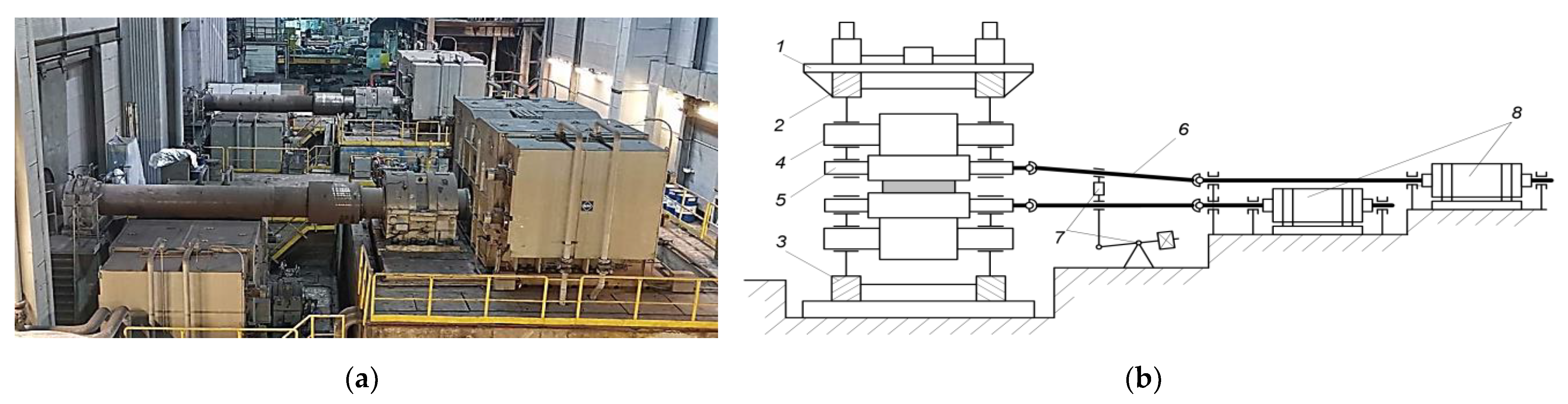
1.2. Characteristics of the Study Object

The rolling mill electromechanical systems’ complexity and their costs keep increasing. Actively monitoring workloads and recording the damage and wear of their critical components is important to keep them efficient and serviceable. These components include spindles that transmit torque from the motors to the work rolls, in order to deform the metal. Therefore, the continuous control of the stand spindle torque is an urgent problem.
Figure 1 shows the motors and spindles of the individual drives of two stands of the hot rolling mill. Figure 1b shows a simplified kinematic diagram for the electromechanical systems of the plate mill stand’s top and bottom rolls. Reference [25] uses a similar diagram to describe the composition of the mill 5000 reversing stand equipment and provides the spindle photo.
The electric drives of the upper and lower rolls have low-speed (slow-speed) high-torque synchronous motors (with electromagnetic excitation) installed. Motor-rated parameters are provided in Table 1.
A linear motor rotational speed of work rolls at the roll maximum diameter is in the range (0–3.17)/7.3 m/s. In compliance with the project, the sheet rolling speed during the last pass does not exceed 7.0 m/s. Thus, the maximum linear speed of the motor is higher than the maximum rolling speed. That is why the stand electric drives are gearless with the frequency control of the rotation speed. Such low-speed motors are commonly installed on the stands with a separate electric drive in the rolls.
According to the authors of [26], “the rolling mill is the basic equipment to manufacture products; the enterprise’s performance depends on its efficiency and reliability. Damage to the main drive system directly affects production and causes huge losses”. A similar conclusion was drawn in [27]: “the rolling mill spindle is always exposed to the environmental impact and fatigue load due to the intermittent turning torque, therefore, a probability of its breakage always exists”. Indeed, [6] notes that “the rolling mill operation is associated with significant wear of spindles, gearboxes, and bearings. Digital diagnostic tools are hardly implementable in them due to harsh operating conditions”. Publications [28,29,30,31,32,33] involve studying the rolling mill spindle wear and fatigue fractures.
Despite the apparent simplicity, spindles are expensive equipment. The problem of keeping them serviceable is relevant for plate mills whose electromechanical systems operate in the reverse mode, with shock loads occurring when the workpiece enters the stand (during the roll bite). The term “workpiece” is herein understood as an intermediate product between the billet (slab) and the finished product (sheet). Shock loads cause premature wear and damage to the mechanical equipment, which is detrimental to the plant. Therefore, along with the measurement (recovery) of dynamic loads, the “participation” of observers in torque-limiting systems is a critical function [34,35]. The authors of publications [36,37,38,39,40,41,42,43] study the practice of using observers to control the shaft line torque.
The observer-based monitoring systems are designed to control the equipment state, prevent accidents, or reveal their causes if an accident occurs. Forecasting the service life of the rolling stand main lines may be an additional problem [44,45,46]. Solving these problems requires, first of all, monitoring the spindle torque directly in the transient process. This will provide control over the signal amplitude and decay time. Thereat, it should be taken into account that indirectly measuring the torque by the motors’ electrical parameters does not allow for obtaining peak loads at the transmission eigen oscillation frequency (10–25 Hz). This technique also does not give acceptable accuracy in variable frequency drives [47].

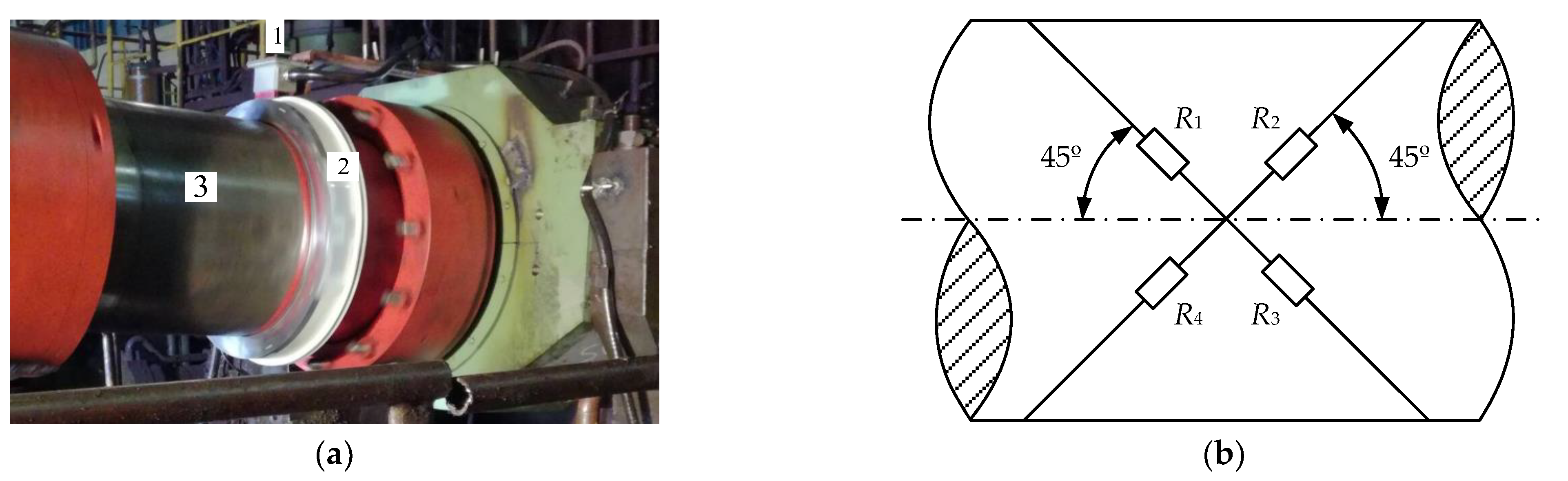
1.3. Direct Torsional Oscillation Measurement System

Conventional systems for monitoring the mechanical transmission state are based on torque sensors, and, as a rule, strain gauges. The authors of publications [48,49] analyze such developments; brief information on the SMSgroup’s (Germany) system installed at the mill 5000 is given below.
Figure 2a shows torque sensor 1 installed on a telemetry ring 2 fixed on the rolling stand’s top roll spindle 3 [50]. A similar sensor is installed on the bottom roll spindle. Figure 2b shows the layout of the strain gauges [51]. At 45° to the output shaft axis, four strain gauges are attached, forming a bridge measuring circuit. The bridge output signals are transmitted to the built-in data acquisition module via an online torque telemetry, and then, after processing, to a remote data server via a USB interface. Controlled torque signals are for information only and do not participate in the drive control algorithms.
The key drawback of the shaft line torque direct measurement systems is a low service life. The reasons are harsh operating conditions and scheduled spindle replacements complicating the re-installation of precision measuring devices (2 in Figure 2a). This necessitated the development of digital twin torque observers, based on drives represented as a two-mass electromechanical system. Publications [52,53,54,55,56,57,58] study two-mass systems with elastic coupling and a gap in mechanical transmissions.
A positive result of implementing the considered monitoring system is the possibility of checking the adequacy of the developed spindle torque observer signals. The observer data and the results of its use in analyzing emergency modes are given below.

1.4. Rationale for the Research Status

An alternative option to the direct measurement of the elastic torque is its calculation with the help of observers of the physical system coordinates [11]. The development of a digital observer of the elastic torque for a two-mass electromechanical system is considered in [50,51]. They consider the elastic torque of the drive shaft (spindle) and the roll speed of the plate mill stand. The results of its pilot tests at the mill 5000 stand electric drives are provided. Paper [50] provides the results of the studies on the automatic control system for the elastic torque developed on this observer basis. The presentation of the roll-mill stand main line with a separate electric drive in the form of a two-mass system, with an elastic shaft and a gap in the spindle connections, is justified in [39]. This paper considers the method for the experimental definition of the two-mass system parameters.
The flaw of this development, which is worth being considered, is the presence of the motor rotation speed differentiation; it negatively affects the reliability and accuracy of signal recovery (see more in the Section 2.2).
The literature review showed that the known elastic torque observers are not used for monitoring the emergency modes of electromechanical systems. Automatic coordinate control systems based on these observers are designed to regulate the dynamic loads of electromechanical systems in operating modes (first and foremost, during the metal bite by rolls). At the same time, the reliable, high-speed measurement of spindle dynamic torques brings about wide prospects for the development of processes aimed at accident prevention, regardless of their causes.
To solve this problem, the following scientific and practical tasks are set:
  • Developing a method for the digital adjustment and calculation of the parameters for the elastic torque observer is suggested. Estimating the reliability of elastic torque recovery in dynamic modes with optimal observer parameters.
  • Experimental studies of the possibility and expediency of the developed observer application to recover the elastic torque in emergency modes occurring at rolling mills. Special focus shall be placed on the modes accompanied by the breakdowns of the equipment at the main lines of electric drives of the stands (accidents with severe aftermath).
  • The development of an emergency braking system to stop the electric drives of the stand upper and lower rolls in the near future. The flaw of the known control systems is the stop of the “emergency” electric drive only. In this case, the hazard of the transmission shaft rotation at the “work” electric drive is not taken into account. As practice has shown, this mode is particularly hazardous at the overlap of the strip on the roll that causes significant damage.
  • The experimental evaluation of the speed and efficiency of the emergency braking system. Such research can be conducted by the method of mathematical modeling. However, the paper considers the application of the digital elastic torque observer, which is referred to in its title. Therefore, emergency modes are researched by the method of passive coordinate observation, which makes it possible to identify signs of a pre-emergency situation.
The substantiation and solution of the aforementioned problems allows one to define the status of research in progress as “scientific”. The results obtained can be widely applied in the electromechanical systems of rolling mills, as well as to other objects with high dynamic loads on the transmission shafts. This confirms the relevance of research and the practical significance of the results.

2. Problem Formulation

2.1. Requirements for a Torque Observer

Rolling mill 5000, under study, and other similar units experience shock loads, the amplitude of which increases to 50–100 ms [58]. Given this fact, the following criteria have been used to develop a digital spindle torque observer:
-
quick response in analyzing the dynamic metal bite process; the sampling time should not exceed 1 ms;
-
the possibility of implementing algorithms in the operating mill’s industrial controller software. Accordingly, the relative simplicity of the developed observer is required.
The last requirement is justified in [50], proving that the implementation of complex computational algorithms (including genetic ones [59,60,61,62]) is inexpedient for operating rolling mills. Implementing them in two-mass electromechanical systems requires the continuous monitoring of the rotational velocity and second mass; this is the stand roll torque. Obviously, the online measurement of these parameters is impossible in practice. The complex algorithms considered in [63,64,65,66] and other papers have been tested on laboratory units with an electric machine as the second mass. Such study results are of academic interest but are inapplicable to the rolling mill electromechanical systems.
An additional requirement for the observer is the possibility of long-term operation under industrial conditions without replacement and maintenance.
Along with the development of an observer that meets these requirements, the paper considers implementing it to analyze the emergency modes occurring at mill 5000. To do this, the principle of using the virtual processing of signals stored as data arrays during accidents is implemented. At the mill 5000, diagnostic data is constantly read by the PDA (process data acquisition) system [67]; all modern rolling mills use such devices. This allowed studying the transient torque processes in the following emergencies: spindle head and roll breakages, emergency shutdown of drives during rolling, etc. Note that the literature sources provide no information on such comprehensive studies.
The ultimate research objective is to develop a system for the rolling mill emergency shutdown when signs of an accident with potentially severe consequences occur. It is aimed at preventing damage to the stand’s main line mechanical equipment, even at the cost of losing the workpiece (which will still be lost in the case of destructive consequences).

2.2. Research Areas

The author of [50] is devoted to developing a digital observer for the rolling mill electromechanical system parameters. It considers the observer of the spindle torque and the plate mill stand roll velocity. The results of its pilot tests in the mill 5000 stand drives are provided.
The observer is built based on the principle of calculating the motor rotational velocity derivative (Figure 3), according to the basic drive motion equation for a single-mass system.
M d y n = M m o t o r M s t = J d ω d t ,
where Mdyn is the dynamic torque to be recovered by the observer,
Mmotor is the electromagnetic motor torque,
Mst is the static load torque,
J is the total torque of inertia,
ω is the angular velocity.
The drawback of this development is the presence of the differentiation of the motor rotational velocity, reducing the system’s noise immunity and stability. In addition, adding a filter limits the response and distorts the recovered signal due to an increase in the measuring circuit equivalent time constant. The desire to eliminate the differentiation and maximally simplify the torque recovery has given impetus to developing a digital observer, considered herein below.
In emergencies when a roll or spindle head breaks, the fast stop of the spindle rotation is critical to reducing the destructive consequences. With such damages, the spindle is a rotating mass with high kinetic energy, fixed only from the motor side. Typical consequences are damages to the spindle balancing jaw, hydraulic cylinders and other equipment. This leads to a long unit downtime and heavy expenses for the elimination of consequences. The motor rotation time after an accident depends on the operator’s response and, as a rule, makes a few seconds. When an online control system identifies breakage, the stand can be actively shut down, which will reduce the damage.
The analysis included the thorough consideration of a severe accident caused by the overlap of the strip on the roll and retracting it into the gap between the work and backup rolls (hereinafter, for brevity, the overlap of the strip on the roll). It is associated with the strip retraction into the gap between the work and backup rolls (Figure 1b), and moving along the bottom roll until it stops rotating. The supposed reason is the strip sticking to the roll surface [68], followed by the retraction under the stand fittings (Figure 4a). Such a situation cannot be controlled during rolling. This has led to the spindle head breakage (Figure 4b), damage to the horizontal/vertical spindle balancing jaw, and other negative consequences.
A similar accident, but with an overlap on the top roll, is described in [69,70]. This caused damage to the roll system components. The way in which a strip stuck in the table rolls due to downward bending when exiting the stand is also shown. We should note that, unfortunately, such accidents regularly occur in plate and broad strip rolling mills, causing long downtime and significant losses for enterprises.
To avoid accidental consequences, control techniques and algorithms should be developed, ensuring emergency braking of the stand drives. An emergency braking system, described herein, has been developed to prevent the considered accident type of overlap of the strip on the roll. Herewith, the system developed should prevent other accidents, regardless of the reasons for their occurrence. With a reliable pre-emergency diagnosis, it should facilitate an emergency drive shutdown before the consequences occur. To avoid false triggering, duplicating diagnostic signs is advisable.
Given the aforementioned, to build an emergency shutdown system based on the observer developed, the following problems should be resolved:
-
justifying pre-emergency signs (preferably, according to several independent criteria);
-
developing a computational procedure, ensuring control over the emergency development;
-
developing a control algorithm, ensuring braking with a rate depending on the drive velocity at the time of the accident.
To solve the latter problem, intensive braking should be provided without the drive entering the torque limiting mode, which is known to cause a loss of motor controllability. For this purpose, developing an adaptive rate controller with a switching structure is planned.

3. Materials and Methods

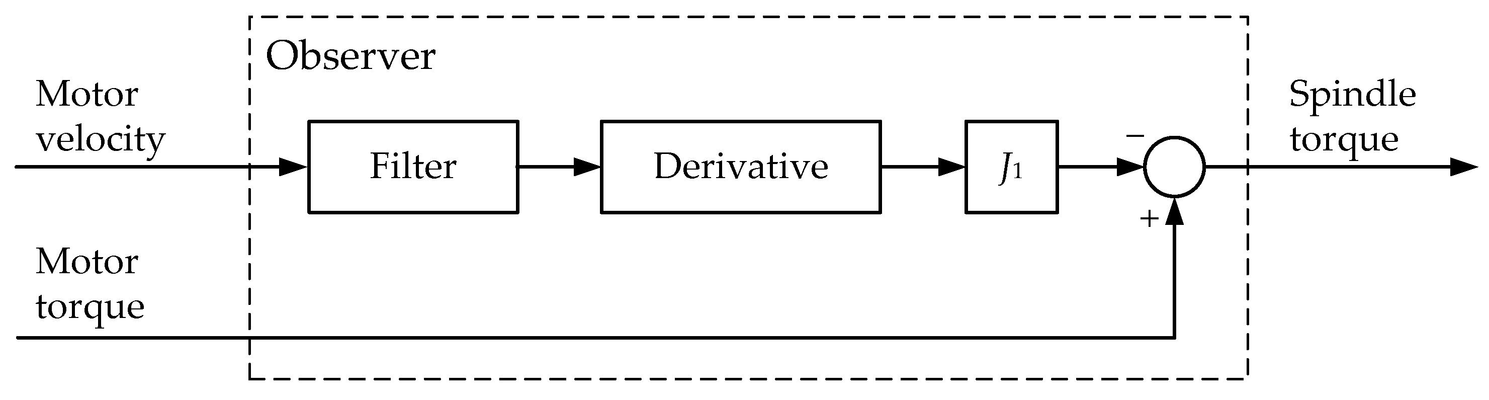
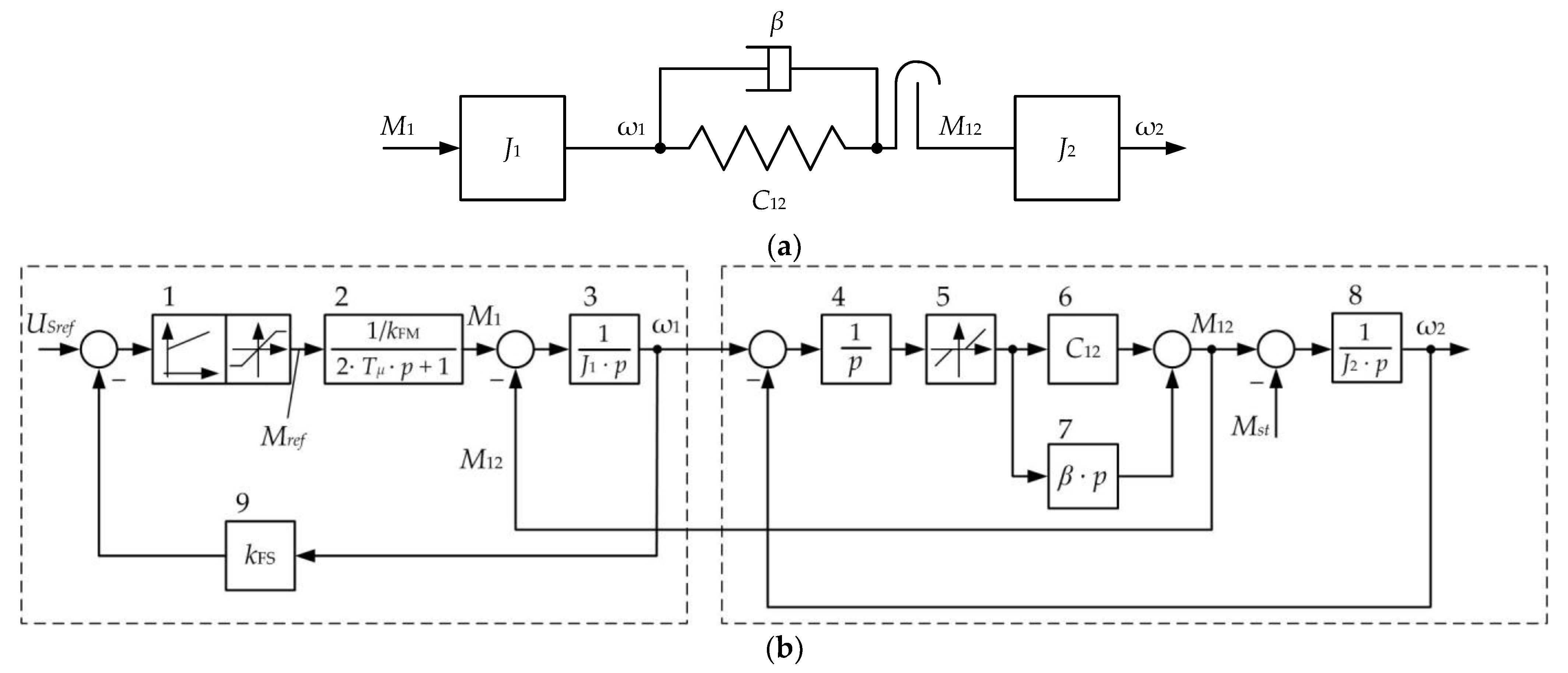
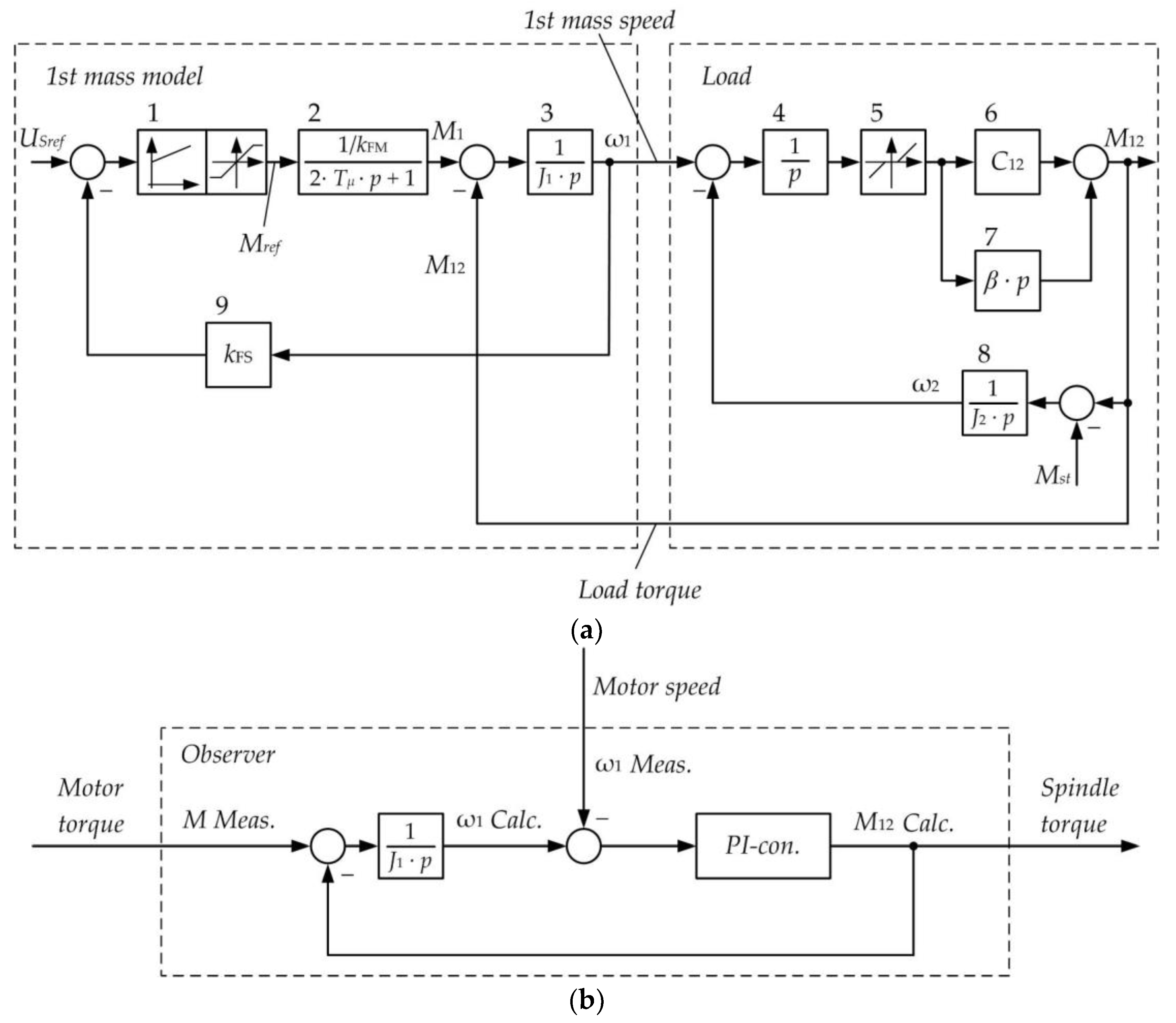
3.1. Developing a Spindle Torque Observer. The Observer Structure

The rolling stand kinematic diagram in Figure 1b shows that the ‘motor-roll’ system can be represented as a two-mass electromechanical system with an elastic coupling and a gap in the mechanical transmission (Figure 5a) [71,72]. Figure 5b shows the block diagram (simplified simulation model) of a drive with a two-loop velocity control system. Such a representation of the rolling stand’s main line is justified in [38], also considering a technique for an experimental definition of the model parameters.
The diagram legend: Tµ is the uncompensated time constant; J1, J2 are the 1st and 2nd mass inertia torques; C12 is the mechanical transmission elastic modulus; β is the coefficient responsible for natural damping (such as viscous friction); Mact is the measured motor torque; M12 is the spindle torque; ω1, ω2 are the motor and roll rotational velocities (of the 1st and 2nd mass, respectively); and kFS for the first mass speed feedback gain; kFM for the motor torque feedback gain in the figure. The model parameters are given in Table 1 [50].
Blocks 3, 5–7 are the typical blocks of a two-mass system model [72]. They determine the nature of transient processes in the mechanical part, including the natural vibration damping (block 7). Block 5 provides gap modelling in gears. The speed feedback is modelled by block 9 with the coefficient kFS. The torque closed control loop is provided by the member 2.
The modified diagram explaining the observer development is given in Figure 6a. It differs from the diagram (Figure 5b) by the signal M12, which is an output signal here. For this purpose, the angular speed signal ω2 is “transferred” through block 8 and the summing component, with a signal of the static torque MC. Such a modification is made in compliance with the rules of structural diagram modification, known from the automatic control theory [73].
For a two-mass system, the following system of differential equations is valid [50]:
d M 1 d t = 1 2 T μ M 1 + 1 2 T μ k F M M 1 r e f , d ω 1 d t = 1 J 1 M 1 1 J 1 M 12 , d M 12 d t = C 12 ω 1 C 12 ω 2 + β J 1 M 1 β J 1 + J 2 J 1 * J 2 M 12 + β J 2 M c , d ω 2 d t = 1 J 2 M 12 1 J 2 M c .
The 1st mass load is the spindle torque. Accordingly, the torque observer can be implemented based on the single-mass system load measurement. To do this, a structure can be applied without calculating the velocity derivatives. Figure 6b shows the diagram describing the proposed torque recovery principle.
To recover the  M 12 C a l c  spindle torque, the velocity error compensation controller (autotuning controller) is used. The difference between the 1st mass (motor) calculated and actual velocity signals is fed to its input. It ‘calculates’ the 1st mass load torque and strives to reduce this difference to zero. The dynamic torque in the model is calculated as the difference between the total motor torque   M 1 a c t , obtained from the PDA system, and the load torque  M 12 C a l c , calculated by the observer. Then, the dynamic torque is integrated with the coefficient (1/J1) and eventually, the 1st mass velocity is calculated.
Thus, the observer implements the operator form of the equation (p is the Laplace operator):
M 12 C a l c = 1 J 1 p M 1 a c t M 12 C a l c ω 1 a c t W r e g ,
where  W r e g  is the autotuning controller’s transfer function (the method of the controller’s synthesis is considered in cl. 3.3). By integration (dividing by p), it generates the calculated torque,  M 12 C a l c , where the minuend  1 J 1 p M 1 a c t M 12 C a l c  is equal to the subtrahend  ω 1 a c t . In this case, the calculated torque,  M 12 C a l c , will be equal to the actual elastic torque,  M 1 a c t , at each time instant. This will provide the accuracy of the torque recovery. The value  1 J 1 p M 1 a c t M 12 C a l c  is the calculated 1st mass velocity. The  M 1 a c t    values are read from the PDA system with a time interval of 1 ms. Since the signal  ω 1 a c t  enters the structure in Figure 6b after the integrator  1 J 1 p , an autotuning PI controller is used. The controller parameters should be chosen to ensure astatic control over the output signal; this is the torque  M 12 C a l c .

3.2. Virtual Parametrization

When developing the observer, the approach justified in [74] is used. It involves simulating processes on a model, with subsequent fine-tuning on the object. When operating with the model, signals are fed to the simulator input directly from the drive. They can be measured online or are pre-archived in the PDA system.
To define the gain and time constant of the controller with the transfer function  W r e g , the virtual parametrization technique is used, comprising the following operations:
Pre-calculation of the controller gain and time constant (P and I part parameters), according to the subordinate control system parameter calculation technique [71].
Developing a simulation model in the Matlab-Simulink or Simscape software environment and subsequently transferring it to the PLC software. For the data exchange with the object, data is exported from the signal archive included in the PDA system.
Direct virtual commissioning. At this stage, the PLC, equipped with the developed computational algorithms, is connected to a physical object. The control algorithms are corrected, and the settings are refined.
A similar technique was successfully applied in the virtual commissioning of the mechatronic systems of a hot strip rolling mill’s reel group [12].
Figure 7 shows fragments of the developed virtual model. The motor rotational velocity and torque signals, imported from PDA, are connected to the virtual top and bottom roll spindle torque observers (LoadObs1 and LoadObs2 in Figure 7a). Figure 7b shows a diagram of a discrete (digital) observer model in Matlab-Simulink. It has been built according to the system of differential Equation (2). In this software, the Laplace transform operator p is denoted by the ‘s’ symbol.
The PI controller was adjusted (Figure 7c) according to the log magnitude technique [73,75]. The procedure for calculating the parameters of the elastic torque observer is provided below.

3.3. Calculation of the Observer Parameters

The observer consists of the following members:
-
integrator with a transfer function
W s p d = 1 J 1 p ,
-
controller with a transfer function
W r e g = K P + K I p = K P 1 + K I K P p = K p 1 + 1 T I   p = K p T I   p + 1 T I   p ,
where  T I = K P K I  is the controller time constant;
KI, KP are P-part and I-part gain ratios.
The transfer function of the open-loop circuit on  M 12  (Figure 6b) is as follows:
W o b j = W s p d W r e g = 1 J 1 p K p + K i p .
The considered observer only has informational functions and does not affect the system processes. Therefore, no high requirements are established for the PI controller setting in terms of providing the closed-loop stability. Thus, when calculating the parameters, it is sufficient to define the cutoff frequency, which determines the time constant of the I-part and the gain ratio of the controller P-part. Below, the solutions to these problems are discussed.
1.
In the course of the setting, the bandwidth and the desired system cutoff frequency should be determined. The setting should provide the following:
-
a set loop bandwidth (lower and upper limits of the permitted frequency range);
-
an open-loop logarithmic amplitude–frequency characteristic (LAFC) slope of −20 dB/dec over a range of ∓, one decade from the cutoff frequency. Further, one should set the system cutoff frequency (as a rule, it should be in the mid of the bandwidth).
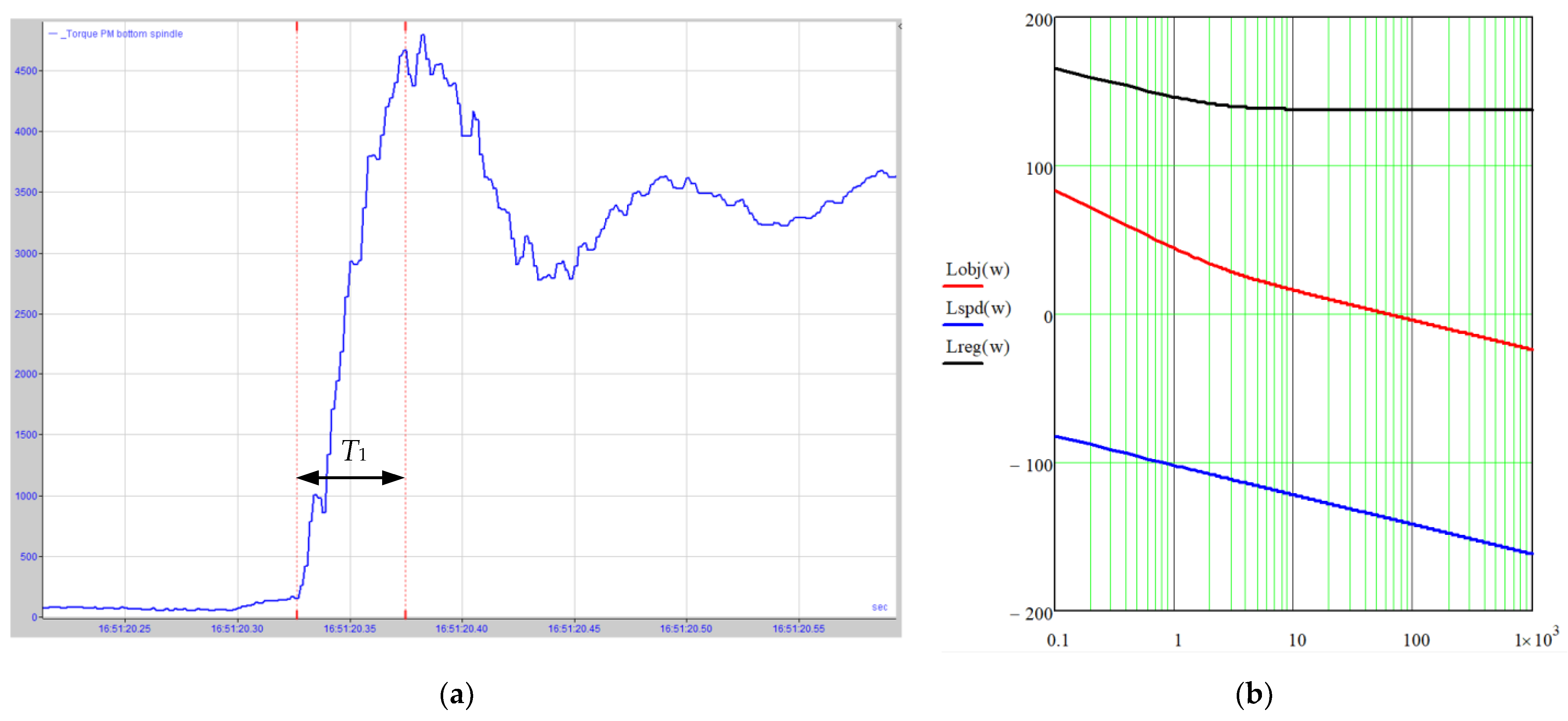
The lower limit of the range ωc.1 is defined by the rate of rise of the elastic torque signal in the load application mode. The signal rise time is defined by the oscillogram from the sensor of elastic torque direct measurement. Figure 8a shows such an oscillogram for the torque application, which is 2.5 times higher than the motor rating torque (if no signal is made, this time can be defined by modelling).
The time T1, if the elastic torque signal rises from zero up to the maximum, is in inverse proportion to the open-loop system. One can consider that
T 1 π ω c .1 .
This is calculated using Figure 8a, where the signal 4480 kN*m changes for 0.05 s, and it follows herefrom.
Consequently, the cutoff frequency of the open-loop system is as follows.
ω c .1 = π T 1 .
An upper range limit is defined by the LAFC slope of the open loop at the cutoff frequency (Figure 8b), providing that, in the range  , one decade from the cutoff frequency, the slope shall be −20 dB/dec. The gain ratio on the integral part is defined by the conditions of the break frequency displacement from the cutoff frequency by 1–2 decades to the left. If the mean value of displacement is taken as being equal to 1.5 decades, then
ω c .2 = ω 1 10 1.5 .  
2.
The controller gain ratio is defined by the condition of the open-loop LAFC approximation to the LAFC desired (Figure 8b). Legend: Lobj—open-loop object the LAFC desired (the observer with an open-loop feedback); Lspd—integrator LAFC with the inertia torque J1; Lreg—controller LAFC. They are built according to the following dependences:
-
LAFC—member spd:
L s p d = 20   L o g 1 J 1   i   ω = 20   L o g 1 J 1 ω   ,
or
L s p d = 20   L o g   J 1 20   L o g   ω   ,
where  i = 1   ;
-
LAFC—member reg:
L r e g = 20   L o g K P T I   ω   i + 1 T I   ω   i ,
or
L r e g = 20   L o g K P 20   L o g T I   ω + 20   L o g 1 + ω   2   T I 2 ;
L o b j = L s p d + L r e g = 20   L o g 1 J 1 ω + 20   L o g K P 20   L o g T I   ω + 20   L o g 1 + ω   2   T I 2 .
The controller “raises” Lspd, which provides Lobj with a desired cutoff frequency. It follows then that
20   L o g   K p = 20   L o g 1 J 1 ω c .1 ; K p = 10       L o g J 1 ω c .1 = J 1 ω c .1
For the generalization, Table 2 provides dependencies to calculate the PI-controller coordinates by the method suggested. Table 2 also provides numerical values and the rated motor parameters used in the calculations. The obtained settings provide the stability of the observer’s closed loop within the real signal frequency range.

4. Implementation

The developed observer was implemented in the mill 5000 stand’s PLC. Each observer’s structure includes series-connected blocks of subtraction, the calculated velocity integrator (CtrFull), the subtraction of the calculated velocity signal from the actual one, and the PI controller (CtrCTPi).

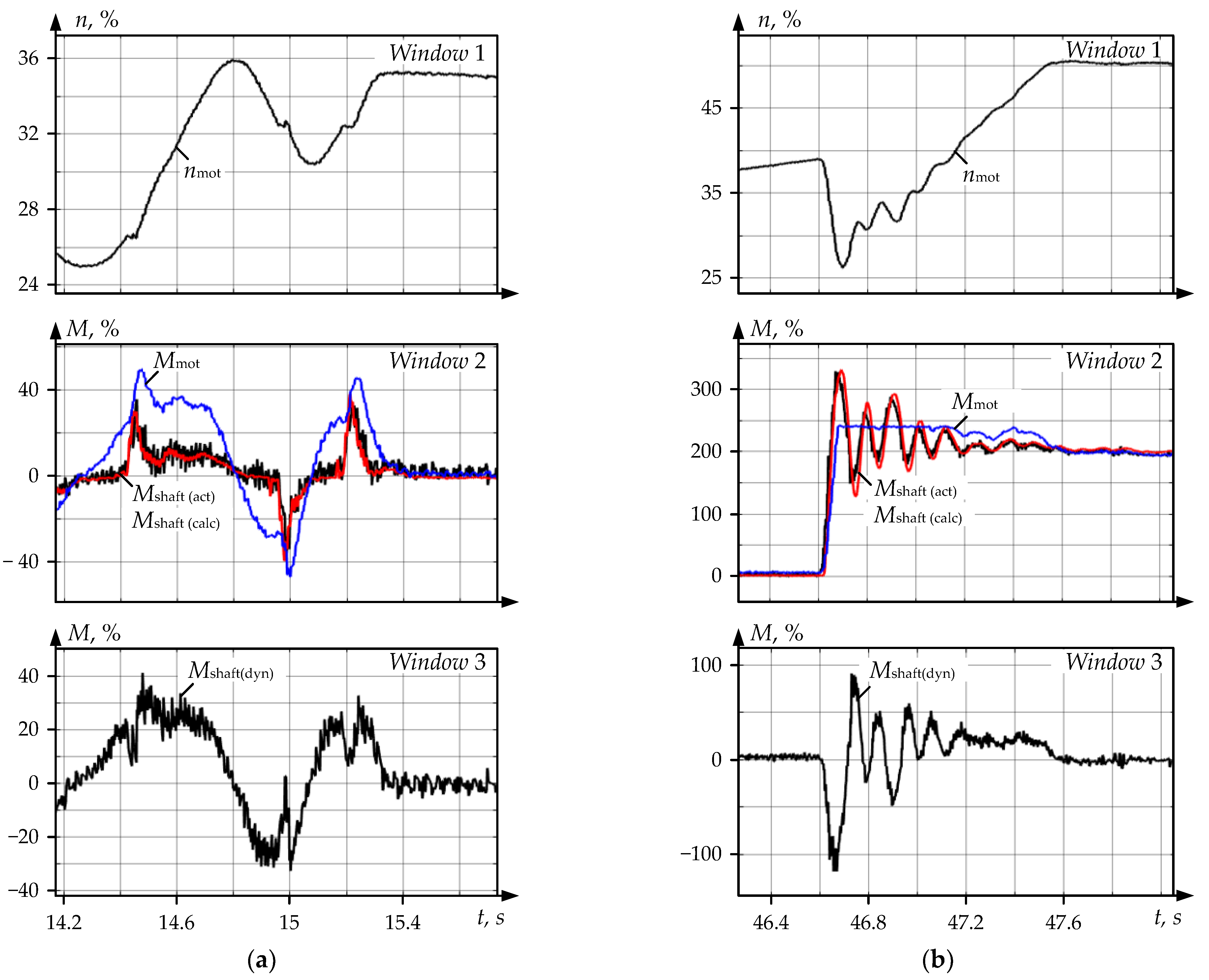
4.1. Checking the Adequacy of Elastic Torque Recovery

After the implementation, the first problem was to check the adequacy of the torque signals recovered by the observers.
When assessing the adequacy of the recoverable values incoming from the observer, the authors propose an approach according to which the speed and torque signals of the motor are imported into the observer’s model (Figure 2b). They can be measured in advance and stored as arrays or fed online to the observer inputs. Here, the pre-recorded waveforms are used; they were imported into Matlab from the IBA PDA.
The adequacy check is conducted by the example of the dynamic mode analysis. The authors suggest a method according to which the following is performed:
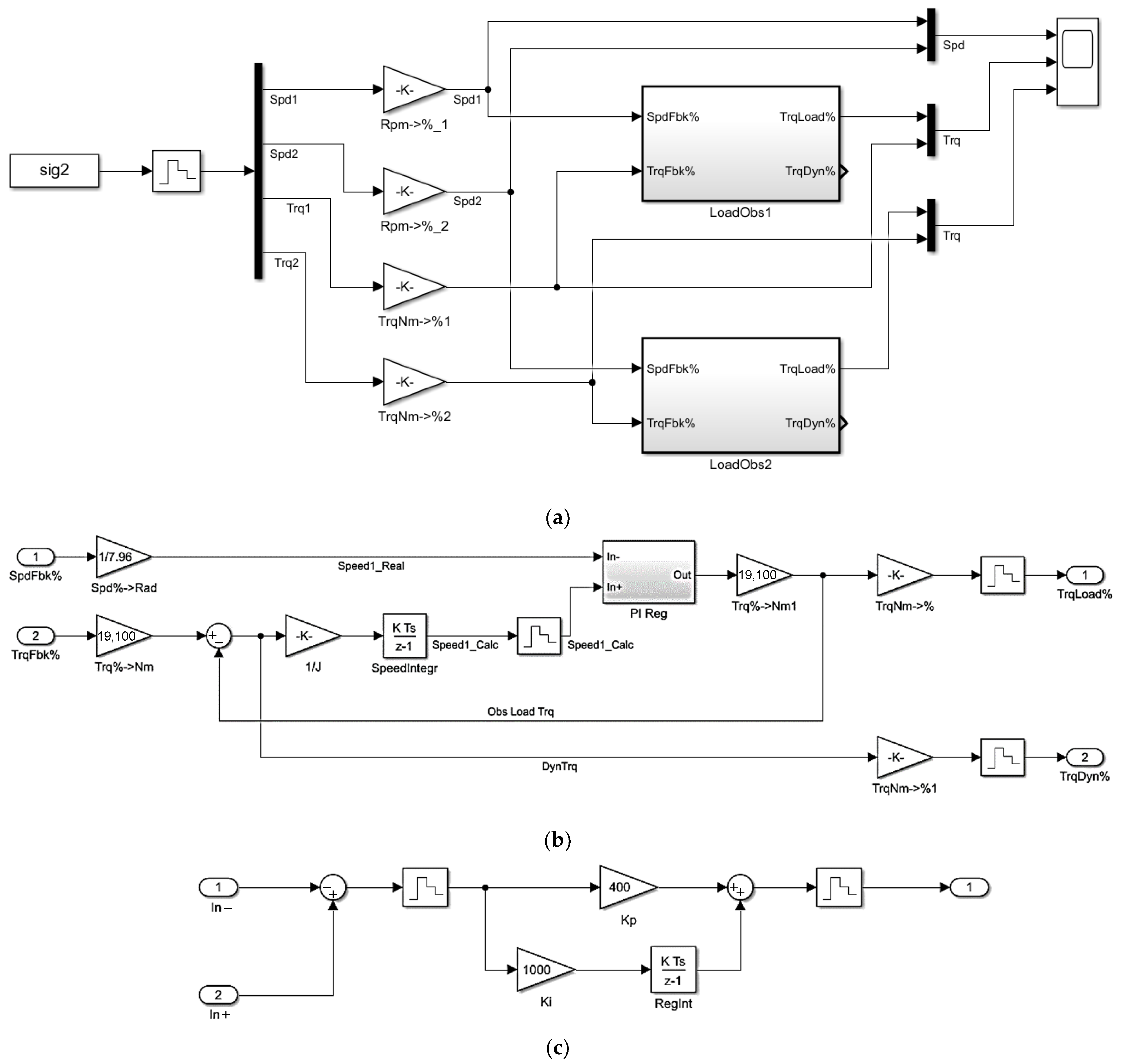
  • The stored data arrays are imported into Matlab and fed to the discrete model input (Figure 7b).
  • Processes are simulated, previously fixed on oscillograms.
  • The oscillograms are compared with the calculated dependencies by superimposing them or comparing the parameters at representative points. To estimate the reliability, statistical processing techniques can be applied (as will be shown below, the case under study does not require using them).
Figure 9a shows oscillograms of the successive acceleration and deceleration of the roll drive.
These modes are the most informative in terms of estimating the observer’s adequacy, since the object’s non-linear properties manifest themselves and are determined by gaps in the spindle joints. During acceleration and deceleration, the gap, respectively, closes and opens [25]. Figure 9b shows similar oscillograms recorded in the shock load mode when the metal enters the stand. Immediately after the bite, the motor torque Mmotor (window 2) reaches the limit of 240% of the rated value, which corresponds to 4580 kN∙m. The torque scale is given in %, and 100% corresponds to the motor’s rated electromagnetic torque equal to 1910 kN∙m.
The dependencies of the spindle torque Mshaft (act) are measured by the PDA system and Mshaft (calc) and recovered by the observer, and completely coincide in both figures. The Mshaft (calc) curve of the torque shown by the observer is against the background of the Mshaft (act) curve of the torque read by the physical measuring system. This allows for concluding that, despite the impact of the gap-determined nonlinearity, the torque signal is recovered with absolute accuracy.
The nonlinear properties of an electromechanical system with a gap cannot be described analytically. However, the provided oscillograms allow for asserting that the proposed signal recovery technique with a reliable observer’s PI controller parametrization helps obtain the recovered signals as close as possible to the physical ones. In this case, the object non-linear properties are automatically considered. A comparative analysis of the processes using mathematical methods is not required since the transient curves coincide completely.
The conclusions drawn are confirmed by the results of studying various dynamic modes of stand drives. The spindle torques occurring in emergency modes, accompanied by equipment breakages, are analyzed below. Note that the literature sources provide no information on such comprehensive studies.

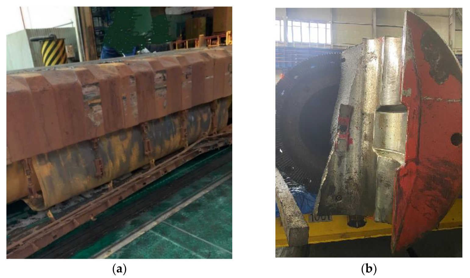
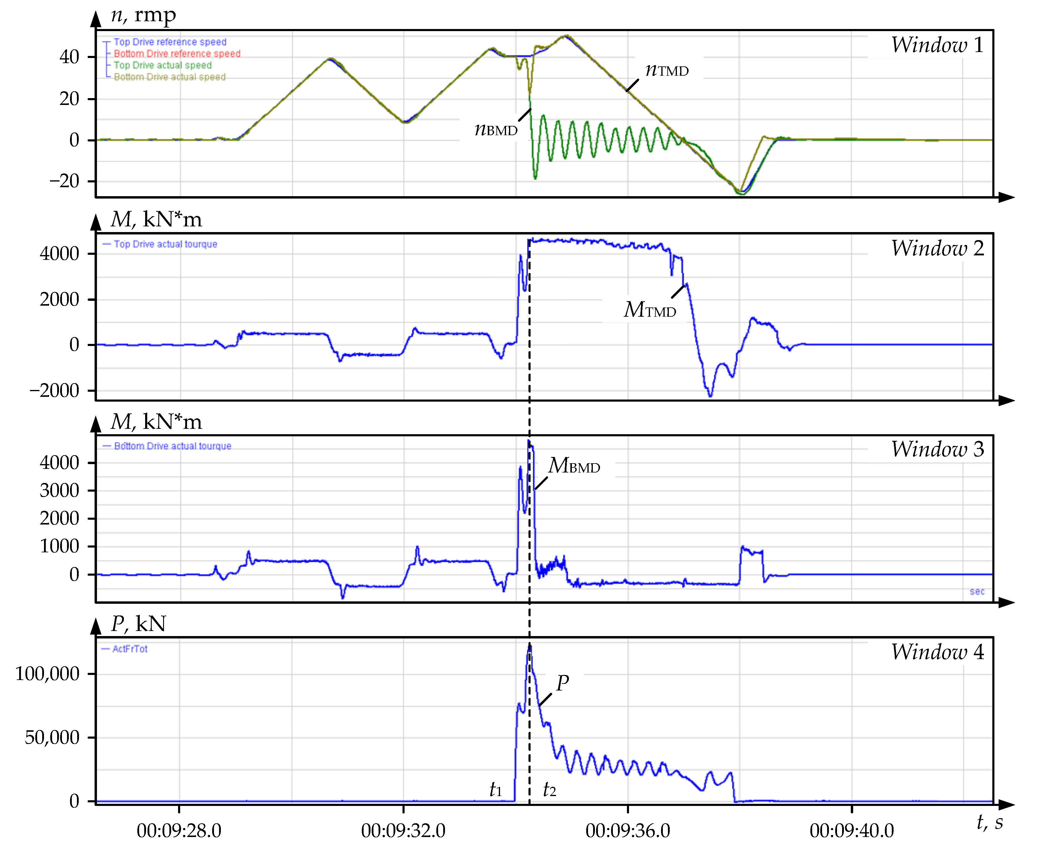
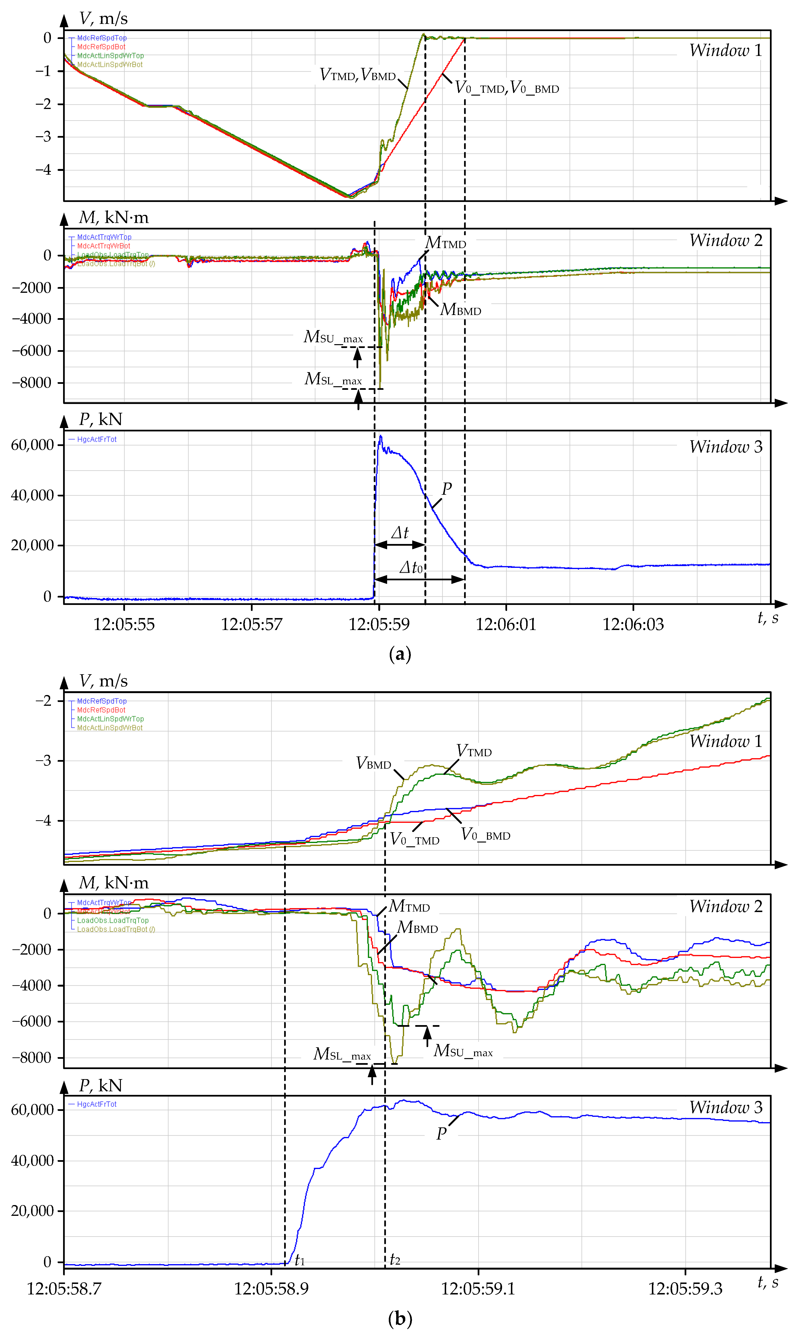
4.2. Dynamic Loads at the Roll Breakage

The process has been analyzed according to the procedure proposed in the previous paragraph, i.e., by processing stored data arrays. Figure 10 shows the velocity and torque oscillograms of the motors of the top (TMD) and bottom (BMD) main drives, recorded by the PDA system during an accident.
The metal bite and the bottom roll breakage occurred, respectively, at time instants t1 and t2. In this case, in the interval t2t3, the top spindle is double-loaded (window 2), since the broken spindle (window 3) is not loaded. After the breakage, damped rotational velocity oscillations nBMD occur (window 1) relative to zero. The MBMD torque (window 3) decreases to zero, however, the motor rotates for another three seconds (window 1) until the operator performs an emergency shutdown. As noted above, this situation is extremely dangerous since the uncontrolled rotation of a loose spindle after a roll breakage may cause devastating consequences.
To estimate the elastic torque, the signals recorded during the accident were exported from PDA to Matlab and processed in a model implementing the observer (Figure 7). The recovered velocity and torque oscillograms are shown in Figure 11. It is seen that the top spindle with an intact roll (window 2) experiences a sixfold overload relative to the rated motor torque. At the motor workload MST = 240%, the amplitude MSTmax = 600%, i.e., it exceeds the load torque by 2.5 times. The bottom spindle torque amplitude (window 3) exceeds the rated load and the workload 5-fold (MSBmax reaches ~500%) and 2-fold, respectively.
The breakage is caused by successively repeated dynamic overloads in previous passes. Analysis of similar oscillograms (not provided herein) confirms this.
Summary. Other emergency modes have been analyzed according to the technique proposed. To do this, data arrays recorded by the PDA system were imported, and oscillograms similar to those shown in Figure 9 were studied. It is concluded that, in all cases, the trouble spindle torque amplitude exceeds the rated load and the workload by, respectively, 4.5–5 (MSBmax reaches ~500%) and 2–2.5 times. The oscillatory nature of the elastic torque is also observed.
Below, the ‘overlap of the strip on the roll’ accident (Figure 4a), causing the most severe consequences, is analyzed.

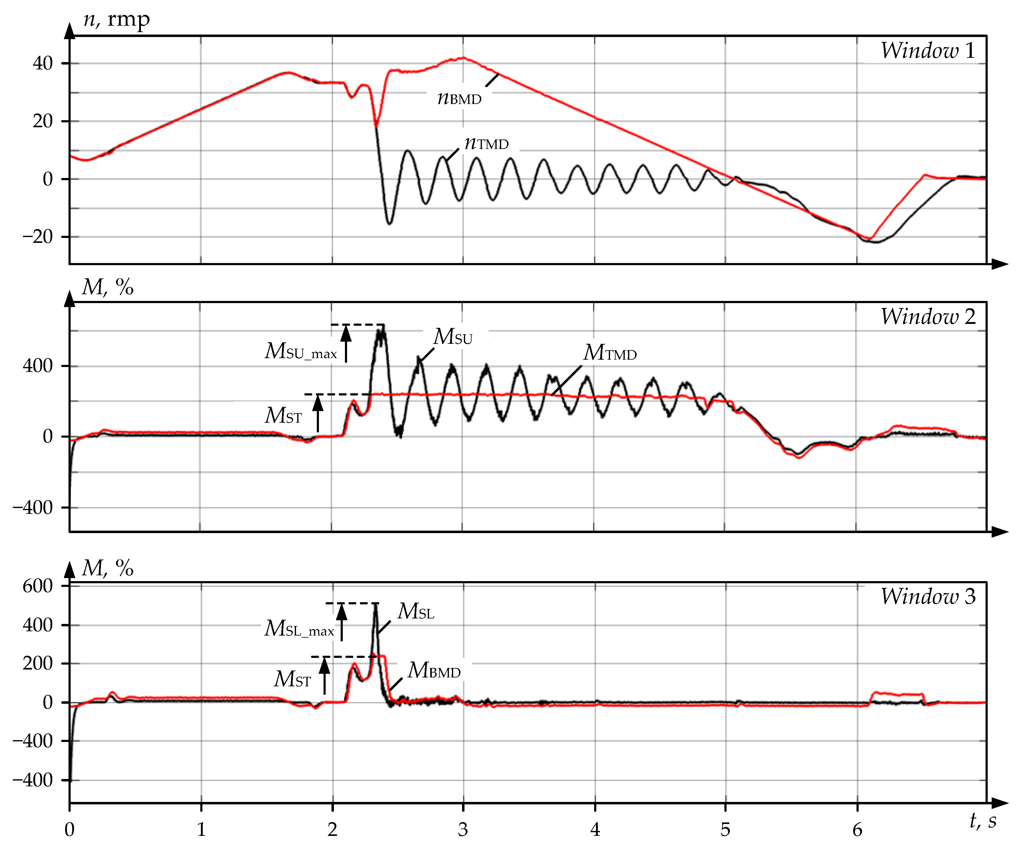
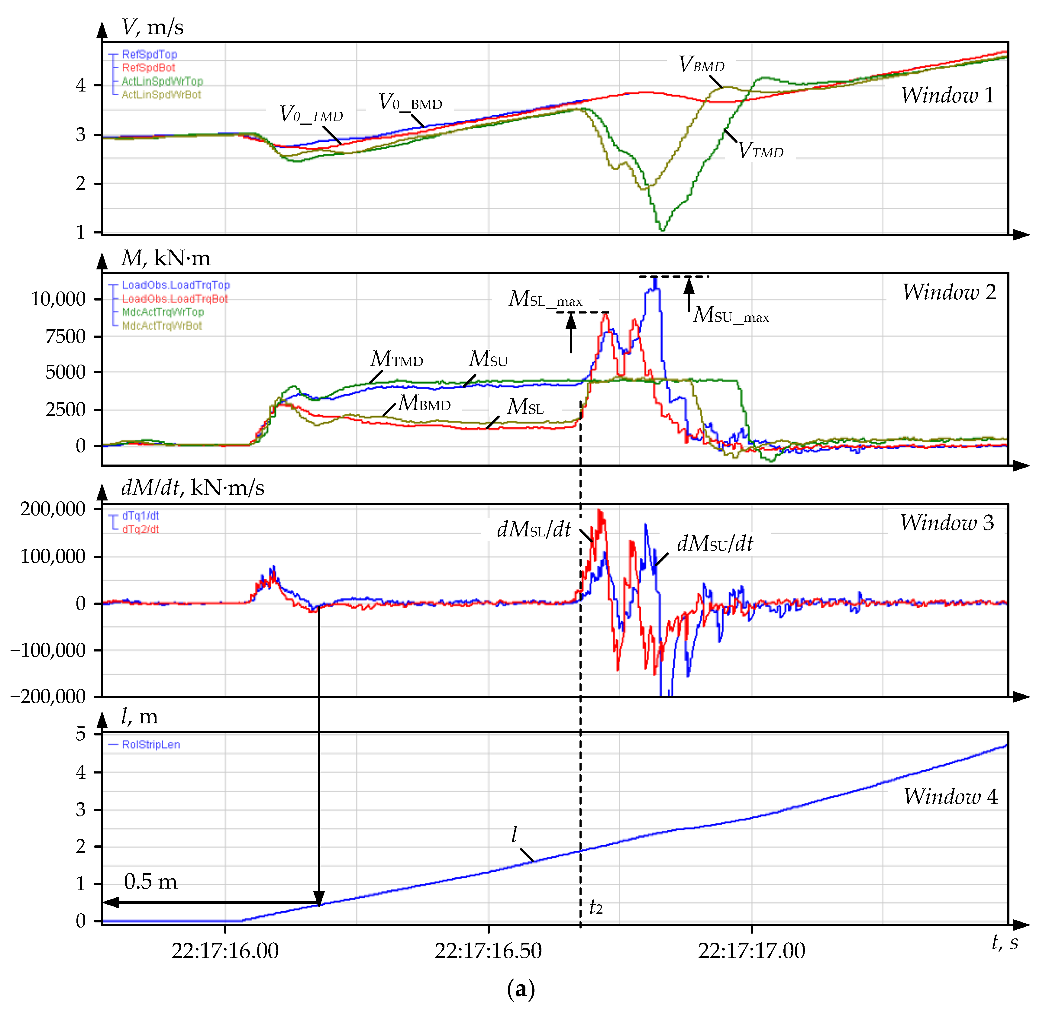
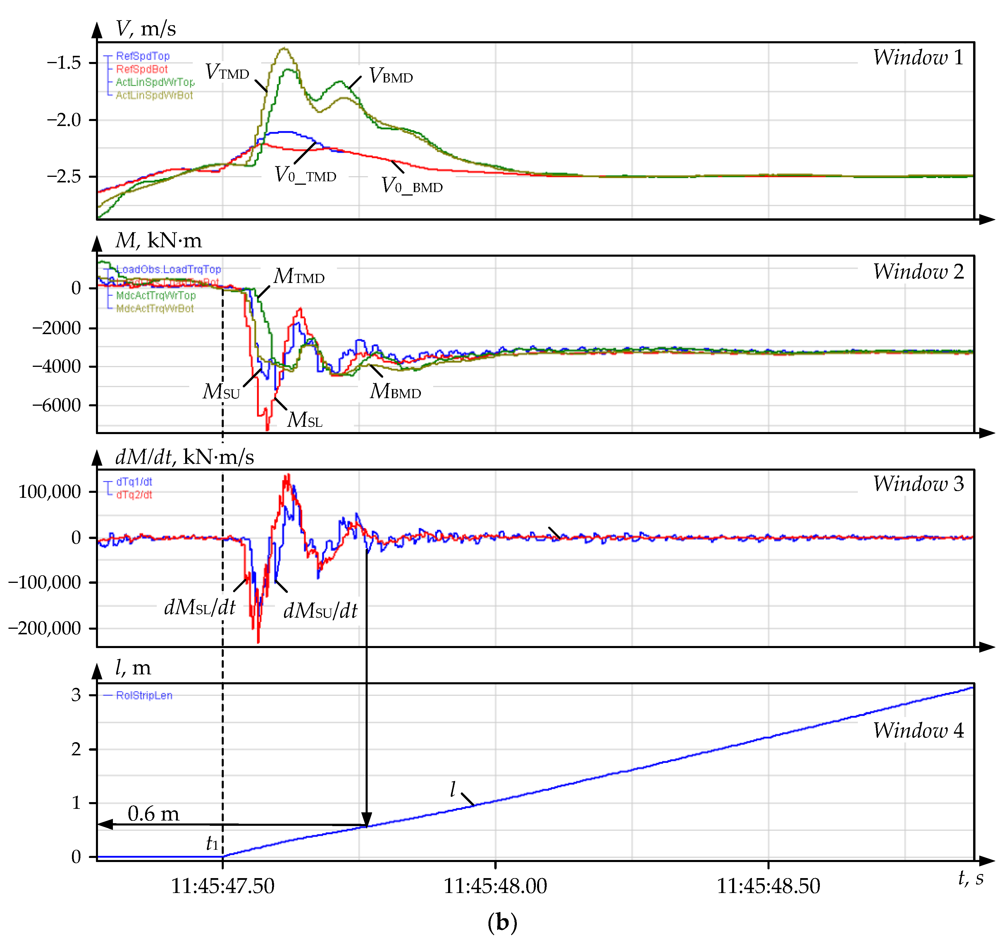
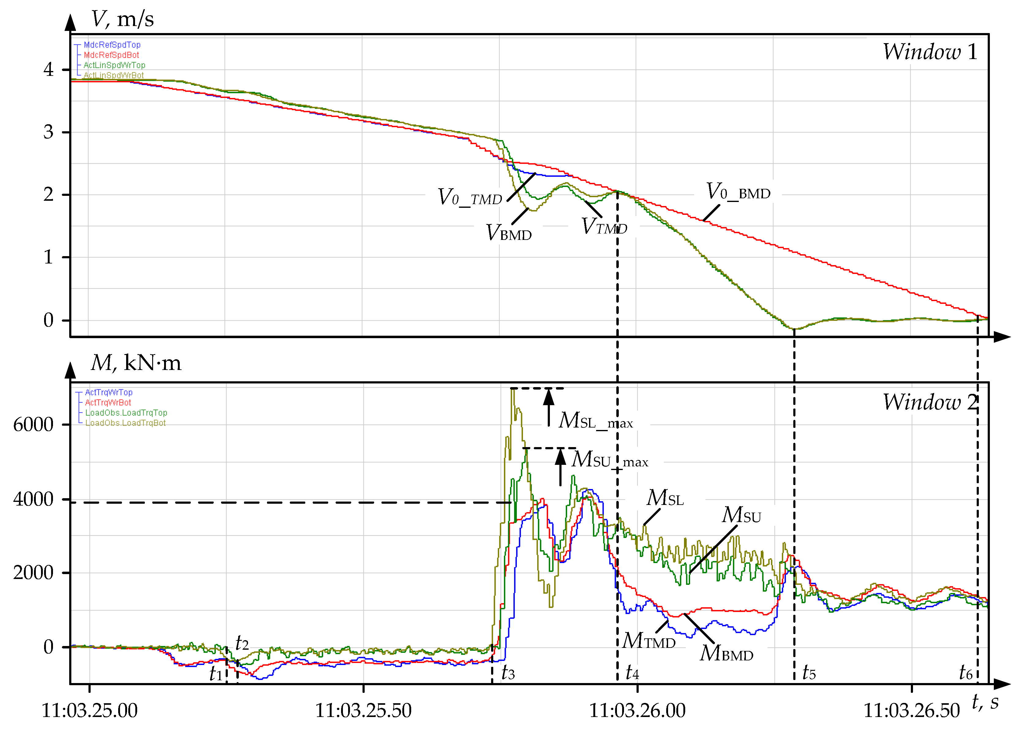
4.3. Analyzing Dynamics in Strip Overlap Mode

As in the previous case, to estimate overloads, the drive parameters recorded by the PDA system and the spindle torque, shown by the observer, have been analyzed. The oscillograms are shown in Figure 12.
The metal bite occurs at the time instant t1. After a breakage at the time instant t2, the MTMD motor torque reaches the limit Mmotor_max = 240%. The spindle torque Mshaft_max is not limited; therefore, it exceeds 12,000 kN∙m or 600% of the rated motor torque. This led to the breakage of the spindle balancing jaw (not shown in the figures) and the spindle head shown in Figure 4b. Such severe consequences of the accident are determined by the rotation of both drives for another 4.5 s (window 1, interval t3t5) after its occurrence. The motors accelerated and decelerated to a stop in the intervals t3t4 and t5t6, respectively.
The major problems that arise in the prevention of emergencies include the timely fix of the accident start and the generation a signal for a quick drive shutdown. In Figure 10, the braking intensity in the interval t5t6 is equal to 2 m/s2, and the motor torques in the braking mode Mmotor_br are insignificant (within 500 kN∙m). This indicates the possibility of increasing the deceleration rate by reducing the emergency shutdown time.

4.4. Diagnostic Signs of the Accident Start

To prevent damage, an emergency drive shutdown is proposed when the spindle torque exceeds a set limit equal to, e.g., 300 %, of the rated motor torque (5700 kN∙m). As noted, the actual problem in implementing this algorithm is precisely fixing the accident start; this is the time instant t2. A possible way is to track the spindle torque rise rate. This is illustrated by the oscillograms in Figure 13a (the oscillograms in windows 1 and 2 differ from those shown in Figure 12 only by the axis scale). The bite occurs at the time instant t1, and windows 3 and 4 show the spindle torque derivative and the rolled part length. Figure 13b shows similar oscillograms recorded in the bite mode during normal rolling. The backward pass (after reverse) is shown, so the torque curves are in the negative range.
The numerical steady and maximum values of the controlled parameters are given in Table 3. It also provides the multiplicity factors kT and kB of the top and bottom spindle torque amplitudes. As is seen, these factors differ for the accident and working bite cases: for the top spindle, kT differs by 1.5 times (2.6 and 1.7), and for the bottom one, kB differs by 1.7 times (4.25 and 2.5). The torque derivatives  d M S T / d t also differ (20,000 and 24,000 kN∙m/s, respectively); d M S B / d t differ similarly. This means that these parameters can be taken as diagnostic signs of an emergency.

5. Developing a Method for the Emergency Stand Drive Shutdown

5.1. The Method Specifics

A method has been developed to prevent accidents, in particular, when the strip overlaps; according to this, a forced mill shutdown is proposed when the elastic torque exceeds a set limit. The following operations are additionally suggested (which are also the method specifics):
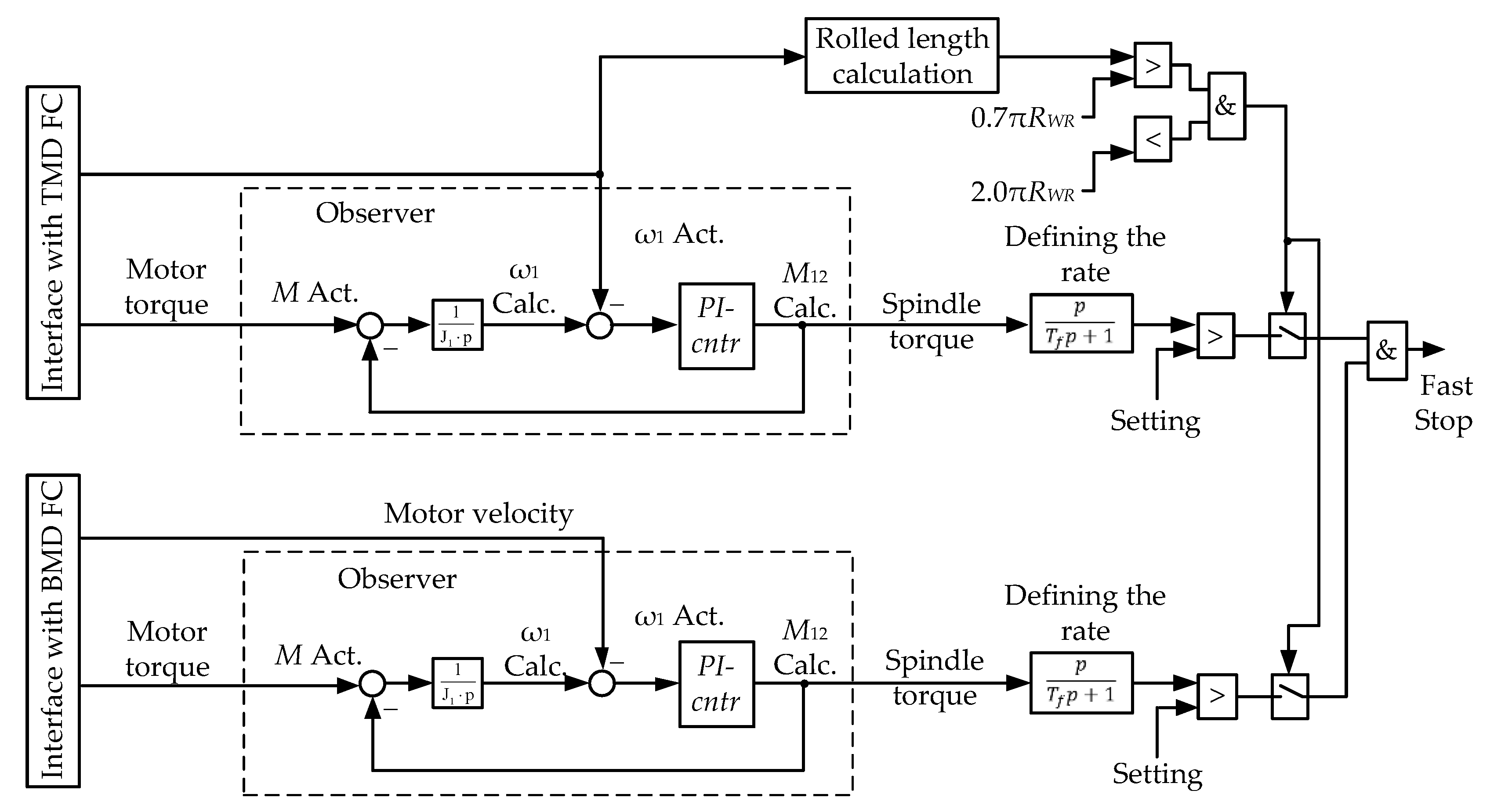
  • Calculate the spindle torque derivative to diagnose a pre-emergency. At a high torque rise rate (e.g., more than 25,000 kN∙m/s), send a signal for emergency braking.
  • To prevent false triggering caused by torque fluctuations occurring during the bite, it is proposed that the rolled part length after the metal enters the stand is monitored. To do this, it is suggested that the torque rise rate at the workpiece length within (0–2) m is monitored, which corresponds to half the roll circumference. After the overlap, the workpiece moves along the circumference with the roll and enters the gap between the work and backup rolls. This occurs when the rolled part length is equal to half the circumference.
L = π R W R ,
where  R W R  is the work roll radius.
With the actual radius  R W R  = 0.64 m, this length L = 2 m. In this case, according to Figure 13a, the transient bite process completely ends at a length of 0.5 m.
3.
Emergency shutdown should take place when the above conditions are met. This will reduce the likelihood of the false triggering of the emergency braking system.
Figure 13b confirms the possibility of meeting the second condition. As can be seen, the transient torque process ends at a length of l ≈ 0.6 m, and the torque does not change with further rolling. Thus, due to the torque’s oscillatory nature with large amplitudes, oscillations cease when the head section is 0.5–0.6 m long. Therefore, the torque rise rate monitoring range (0–2 m) was adopted with a margin.

5.2. The Emergency Shutdown System Structure

To implement the method, a roll drive control system was developed, the diagram of which is shown in Figure 14. It comprises TMD and BMD control channels with a developed observer each. Other blocks (length calculation, logical blocks, etc.) are connected according to the aforementioned system functions.
The block diagram of the control system shown in Figure 15a describes the proposed fast stop algorithm. It is implemented in the stand PLC using special velocity-setting software. The Figure legend is as follows: A1—block of distributing tasks, considering the reduction (for drives of roller tables before and after the stand, and the stand motors); RC1, RC2—the PLC’s and operator’s velocity rate controllers; and RC3—fast stop rate controller. The dashed line shows the RC3 rate-setting loop implementing the control algorithm developed. It is described below. In Figure 15b: V1, V2, V3—velocity settings for the mechanisms located after the stand, the stand motors, and the mechanisms located before the stand, respectively; U3RC3 output signal.
With the standard shutdown system configuration, the output signal U3 (Figure 15b) decreases from 1 to 0 (in p.u.) in 2.5 s. The total drive velocity setting is multiplied by this signal, resulting in a shutdown time of 2.5 s, regardless of the current velocity (V1, V2, V3). The drive fulfills the stand controller’s command, resulting in an unreasonably long braking time at velocities lower than V1. Thus, a constant deceleration rate is a drawback of this algorithm.

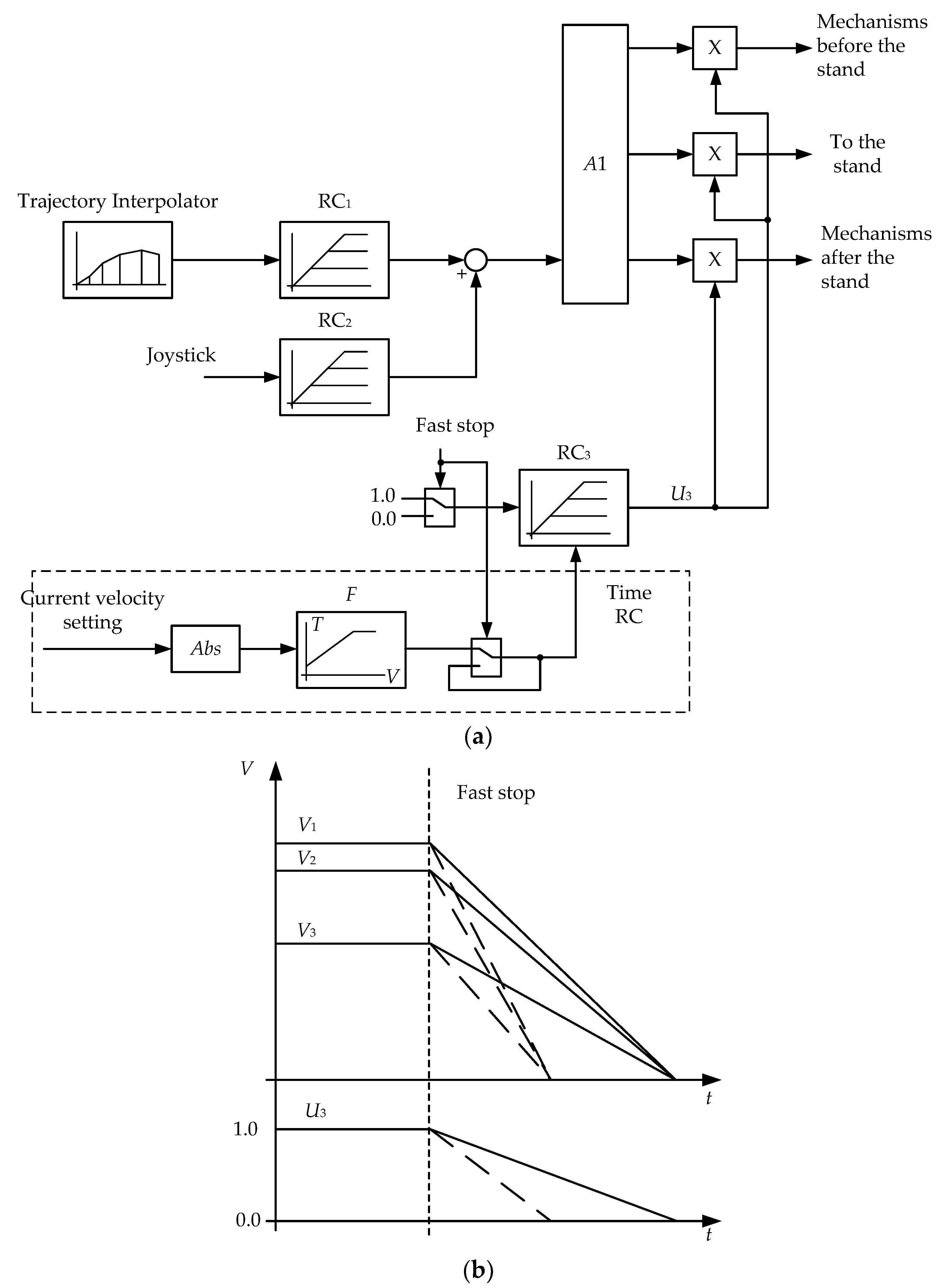
5.3. Developing an Adaptive Rate Controller

It is proposed that an emergency shutdown with an adaptive rate controller is provided, the slope of the characteristics of which depends on the drive’s velocity. Such an RC’s output signals are shown in Figure 15b with dashed lines. Its development requires the justification of the deceleration rates depending on the rolling speed (actually, the pass number). When the torque increases unacceptably or another pre-emergency occurs, the output signal U3 decreases from 1 to 0 at a rate  a 3 = 1 T 3 .
To do this, a variable RC rate should be set:  T 3 = f ( V r e f ) . The diagram fragment highlighted with a dashed line in Figure 15a forms a special fast stop rate setting module. Block F implements this dependency and ensures a synchronous shutdown of all mechanisms with a calculated rate. In combination with the emergency braking system in Figure 14, adaptive RC will prevent the development of accidents. In the considered case, the most dangerous accident caused by strip overlap will be prevented.
Despite the simplicity, the presented development is new. The literature sources provide no information on such adaptive RC algorithms and structures (except for the adaptive braking of electric and hybrid vehicles [76,77]). The proposed method is effective in preventing both the considered and other accidents. The system that triggers the stop drives at an unacceptable overload when the workpiece enters the stand is shown below.

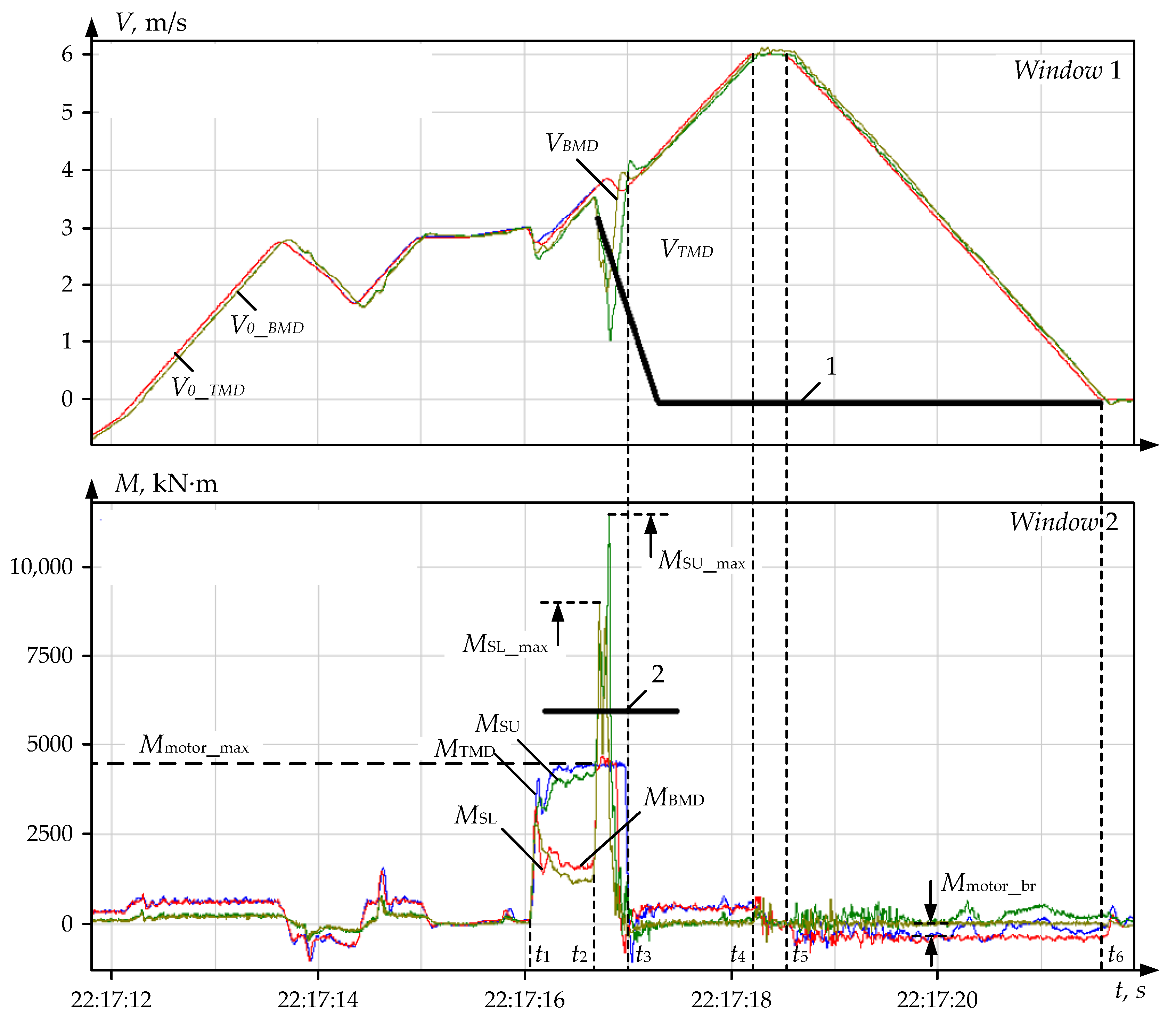
5.4. Testing the Algorithm

The emergency shutdown algorithm was tested on the mill using the passive experiment technique. The shutdown occurred when the spindles were multifold overloaded by torque in the metal bite mode. Two cases of using the algorithm are analyzed below.
Case 1. Figure 16a shows the pre-emergency mode oscillograms (Figure 16b shows them on an increased time scale). To recover torques, the data arrays recorded during the accident were exported, and the signals were further recovered using an observer. The processes run in the backward rolling mode, the velocity and torque oscillograms, are in the negative range. The absolute numerical values are further taken with the ‘-‘ sign omitted.
The bite occurred at the time instant t1 (Figure 16) at a velocity of 4.4 m/s in the braking mode, when the plays in the spindle joints were opened [25]. The specified velocity is almost twice that of the working bite (2.5 m/s). This caused a dynamic shock; the BMD spindle torque amplitude MSB_max exceeded 8000 kN∙m. The torque overload was 430% of the rated value. The maximum top spindle torque MST_max exceeded 4200 kN∙m, which corresponds to 220% of the rated value.
The developed system (Figure 14) allowed for generating a signal for emergency drive braking. It was sent at the time instant t2 (Figure 16b) after the spindle torque exceeded the set value of 7000 kN∙m. The BMD motor deceleration time Δt (Figure 16a) was about 0.7 s, which was approximately two times less than the emergency braking setting time Δt0 with the standard configuration. This fast stop is an advantage, since the motor (and spindle) rotation will be stopped two times faster.
Case 2. Figure 17 shows oscillograms of the emergency mode, similar to the previous one. Immediately after the bite at the time instant t3, the bottom roll spindle torque MSB increased to MSBmax = 7000 kN∙m. Thereat, the top roll spindle torque increased to MStmax = 5200 kN∙m. As in the previous case, one of the reasons is the bite of the workpiece in the motor braking mode with open gaps in the spindle joints. This is confirmed by small negative ‘bursts’ of the motor torques MTMD and MBMD at the time instants t1 and t2, preceding the bite.
The implemented algorithm allowed sending a signal of an unacceptable torque increase to the velocity control system. As a result, an emergency shutdown of drives occurred in the interval t4t5 for 0.25 s. Such a delay is not critical in terms of preventing further breakages, however, decreasing it is desirable to reduce overloads. With the system’s design configuration, braking would occur in the interval t4t6, and the shutdown time would be 0.6 s. Thus, the implemented algorithm allows a 4-fold reduction in the drive’s emergency shutdown time.
The considered emergency modes confirm the expediency of using an observer for an adaptive emergency shutdown of drives at the spindles’ dynamic overload. They indirectly confirm the operability of the developed emergency shutdown system. It has been additionally adjusted as follows:
  • The dynamic torque setting has been increased to prevent false triggering. An additional torque derivative signal has been introduced into the triggering logic system.
  • To justify the optimal deceleration rate after the bite and to estimate the technical efficiency of the developed solutions, studies were performed using mathematical simulation. Their results are bulky and may be the subject of a separate publication.

6. Discussion of the Results

The studies confirm that in all the considered modes, the motor torque is limited by the control system at 240% of the rated value. Thereat, the spindle torque amplitudes exceed the rated value by 3.5–5 times. As a result, fatigue failures occur, causing damage to mechanical equipment. This confirms the expediency of continuous spindle torque monitoring using the developed observer.
Compared to ‘contact’ measuring systems (Figure 2a), the developed observer has the following advantages:
-
simplicity and high reliability;
-
no need for any maintenance;
-
no value in fact, since it is a piece of software.
The spindle torque data should be stored in a special database while amplitudes exceeding a set limit should be displayed on the operator’s monitor. This allows avoiding successively repeated dynamic shocks that cause increased fatigue failures.
To take full advantage of the observer, it is advisable to develop and implement the following at the mill:
1.
A spindle overload monitoring system ensuring the recording and calculation of torque overloads exceeding the set limits.
2.
A technique for determining the expected spindle life based on the calculation of spindle overloads and the estimation of the torque amplitudes.
3.
Methods for limiting dynamic loads. Currently, at the mill 5000, the drive control system operates, reducing loads due to the drive acceleration before the bite and short-term intensive braking after the bite [58,78]. The following should be performed additionally:
3.1
Justifying the optimal bite speed depending on the workpiece thickness and the absolute reduction (in fact, the pass number). This is determined by different deformation zone filling rates in the stand at different reductions. The biting speed varies from pass to pass, from 2 to 5 m/s. Absolute reductions vary from 30 mm in the first passes to 2 mm in the last ones. These factors affect the dynamic torque magnitude.
3.2
Developing and implementing a method for adaptive braking after the bite. The difference between this and the implemented version is that the braking rate is calculated on the model and then automatically set individually for each pass.
3.3
The issue of calculating (recovering) the uncontrolled mass. The roll velocity should also be resolved.
The solutions to the listed problems will allow transforming the developed observer into the spindle technical condition online monitoring system. On this basis, a complex of solutions aimed at preventing accidents and mitigating their consequences will be implemented.

7. Conclusions

  • A digital observer of the top and bottom roll spindle torques has been developed, which is a fragment of the industrial controller software. The observer’s key component is an autotuning PI controller, which allows replacing differentiation with integration. This is an advantage over conventional technical solutions. The second advantage is its easy adjustment. Non-recovery of the second mass velocity signal is its disadvantage compared to the development [50]. This problem can be solved in the course of further research.
  • The virtual observer parametrization was performed, and after fine-tuning in Matlab-Simulink, the computational algorithm was exported to the PLC software. The equations for calculating the autotuning controller parameters are provided. Oscillograms are provided, confirming that, with the proper PI controller parametrization, the proposed algorithm allows achieving an absolute match of the recovered and measured (physical) signals in dynamic modes occurring during the rolling cycle.
  • The spindle torques were analyzed by processing data arrays under the following emergency modes:
    • overlap of the strip on the roll;
    • dynamic overloads when the metal enters the stand;
    • emergency modes causing breakage of the roll and spindle joint.
Note that rolling mill spindle torques have been studied in emergency modes for the first time.
The main problems that prevent these modes are the timely fix of the accident start and the generation of an emergency shutdown signal by the drive control system.
4.
A method for preventing accidents has been developed, which suggests isolating the spindle torque derivative and performing a forced shutdown of the mill at a high torque rise rate (more than 25,000 kN∙m/s). This will prevent further spindle rotation and accidental consequences. The structure of the control system that allows for emergency braking at the strip overlap is proposed. To implement it, an adaptive braking rate controller with a switching structure has been developed.
5.
The developed observer is currently in commercial operation. The use of the received spindle torque signals in the drive control systems is not supposed. They are mainly aimed at providing information on the torque amplitudes in dynamic modes during the metal bite. The observer also allows monitoring pre-emergencies to prevent accidents or reveal their causes if an accident occurs.
The described technical solutions are recommended for implementation in the electromechanical systems of rolling mills operating with shock loads. In combination with the developed torque limiting techniques [78,79,80,81], they will reduce the unproductive expenses of enterprises by reducing the accident risk of the key equipment. This is a practical contribution to the digitalization of rolling mills.

Author Contributions

Methodology, A.S.K., V.R.G. and A.A.R.; ideas A.A.R., V.R.K. and B.M.L.; software B.M.L. and O.A.G.; validation V.R.K.; formal analysis V.R.K. and V.R.G. All authors have read and agreed to the published version of the manuscript.

Funding

This work was financially supported by the Moscow Polytechnic University within the framework of the grant named after Pyotr Kapitsa.

Conflicts of Interest

The authors declare no conflict of interest.

References

  1. Murri, M.; Streppa, E.; Colla, V.; Fornai, B.; Branca, T.A. Digital Transformation in European Steel Industry: State of Art and Future Scenario. Blueprint “New Skills Agenda Steel”: Industry-Driven Sustainable European Steel Skills Agenda and Strategy (ESSA). Deliverable D2.1 Version 1 (Status: 30.09.2019). Available online: https://www.estep.eu/assets/Uploads/Technological-and-Economic-Development-in-the-Steel-Industry-ESSA-D6.1.pdf (accessed on 10 November 2022).
  2. Buchmayr, B.; Degner, M.; Palkowski, H. Future Challenges in the Steel Industry and Consequences for Rolling Plant Technologies. BHM Berg- und Hüttenmännische Monatshefte 2018, 163, 76–83. [Google Scholar] [CrossRef]
  3. Ha, D.H.; Kim, R. Nonlinear Optimal Position Control with Observer for Position Tracking of Surfaced Mounded Permanent Magnet Synchronous Motors. Appl. Sci. 2021, 11, 10992. [Google Scholar] [CrossRef]
  4. Park, C.Y.; Kim, J.W.; Kim, B.; Lee, J. Prediction for Manufacturing Factors in a Steel Plate Rolling Smart Factory Using Data Clustering-Based Machine Learning. IEEE Access 2020, 8, 60890–60905. [Google Scholar] [CrossRef]
  5. Ohlert, J.; Sprock, A.; Sudau, P. Digitalization in hot and cold rolling mills. Mat. Sci. Forum 2016, 854, 215–224. [Google Scholar] [CrossRef]
  6. Bai, Q.; Jin, B.; Gao, Y.; Zhang, H. An Online Fault Pre-warning System of the Rolling Mill Screw-down Device Based on Virtual Instrument. Sens. Transducers 2014, 168, 1–7. [Google Scholar]
  7. Wang, Q.; Fang, Y.; Zhou, Z.; Zuo, J.; Xiao, Q.; Zhou, S. Reliability assessment of the vertical roller mill based on ARIMA and multi-observation HMM. Cogent Eng. 2017, 4, 1270703. [Google Scholar] [CrossRef]
  8. Liu, L.L.; Wan, X.; Gao, Z.; Li, X.; Feng, B. Research on modelling and optimization of hot rolling scheduling. J. Ambient. Intell. Human. Comput. 2019, 10, 1201–1216. [Google Scholar] [CrossRef]
  9. Klinkov, M.; Feist, R. The Virtual Rolling Mill—Enhancing Product Development and Commissioning. Mater. Sci. Forum 2016, 854, 231–236. [Google Scholar] [CrossRef]
  10. Hu, Z.; Wei, Z.; Sun, H.; Yang, J.; Wei, L. Optimization of Metal Rolling Control Using Soft Computing Approaches: A Review. Arch. Computat. Methods Eng. 2021, 28, 405–421. [Google Scholar] [CrossRef]
  11. Radionov, A.A.; Karandaev, A.S.; Loginov, B.M.; Gasiyarova, O.A. Conceptual Directions of Creating Digital Twins for Electrotechnical Systems of Rolling Mill Facilities. Russ. Electromechanics 2021, 64, 54–68. [Google Scholar] [CrossRef]
  12. Karandaev, A.S.; Gasiyarov, V.R.; Radionov, A.A.; Loginov, B.M. Development of Digital Models of Interconnected Electrical Profiles for Rolling–Drawing Wire Mills. Machines 2021, 9, 54. [Google Scholar] [CrossRef]
  13. Liebenberg, M.; Jarke, M. Information Systems Engineering with Digital Shadows: Concept and Case Studies. Lect. Notes Comput. Sci. 2020, 12127, 70–84. [Google Scholar] [CrossRef]
  14. Holopainen, M.; Saunila, M.; Rantala, T.; Ukko, J. Digital twins’ implications for innovation. Technology Analysis & Strategic Management 2022, 34. published online. [Google Scholar] [CrossRef]
  15. Wright, L.; Davidson, S. How to tell the difference between a model and a digital twin. Adv. Model. Simul. in Eng. Sci. 2020, 7, 13. [Google Scholar] [CrossRef]
  16. Kritzinger, W.; Karner, M.; Traar, G.; Henjes, J.; Sihn, W. Digital Twin in manufacturing: A categorical literature review and classification. IFAC-PapersOnLine 2018, 51, 1016–1022. [Google Scholar] [CrossRef]
  17. Fuller, A.; Fan, Z.; Day, C.; Barlow, C. Digital Twin: Enabling Technologies, Challenges and Open Research. IEEE Access 2020, 8, 108952–108971. [Google Scholar] [CrossRef]
  18. Singh, M.; Srivastava, R.; Fuenmayor, E.; Kuts, V.; Qiao, Y.; Murray, N.; Devine, D. Applications of Digital Twin across Industries: A Review. Appl. Sci. 2022, 12, 5727. [Google Scholar] [CrossRef]
  19. Kalachev, Y.N. State Observers in Vector Electric Drive; EFO: Moscow, Russia, 2015. [Google Scholar]
  20. Ruppert, T.; Abonyi, J. Integration of real-time locating systems into digital twins. J. Ind. Inf. Integr. 2020, 20, 100174. [Google Scholar] [CrossRef]
  21. Ladj, A.; Wang, Z.; Meski, O.; Belkadi, F.; Ritou, M.; Da Cunha, C. A knowledge-based Digital Shadow for machining industry in a Digital Twin perspective. J. Manuf. Syst. 2020, 58, 168–179. [Google Scholar] [CrossRef]
  22. Schluse, M.; Priggemeyer, M.; Atorf, L.; Rossmann, J. Experimentable Digital Twins—Streamlining Simulation-Based Systems Engineering for Industry 4.0. IEEE Trans. Ind. Inform. 2018, 14, 1722–1731. [Google Scholar] [CrossRef]
  23. VanDerHorn, E.; Mahadevan, S. Digital Twin: Generalization, characterization and implementation. Decis. Support Syst. 2021, 145, 113524. [Google Scholar] [CrossRef]
  24. De Kooning, J.D.M.; Stockman, K.; De Maeyer, J.; Jarquin-Laguna, A.; Vandevelde, L. Digital Twins for Wind Energy Conversion Systems: A Literature Review of Potential Modelling Techniques Focused on Model Fidelity and Computational Load. Process. 2021, 9, 2224. [Google Scholar] [CrossRef]
  25. Gasiyarova, O.A.; Karandaev, A.S.; Erdakov, I.N.; Loginov, B.M.; Khramshin, V.R. Developing Digital Observer of Angular Gaps in Rolling Stand Mechatronic System. Machines 2022, 10, 141. [Google Scholar] [CrossRef]
  26. Hou, Y.; Kong, J.Y.; Wang, X.D. Research on Online Monitoring for the Main Drive System of Rolling Mill. Appl. Mech. Mater. 2011, 127, 444–448. [Google Scholar] [CrossRef]
  27. Kim, E.S. Fatigue life evaluation of spindle of rolling mill using ADINA structure and WINLIFE. J. Mech. Sci. Technol. 2020, 34, 3991–3996. [Google Scholar] [CrossRef]
  28. Antsupov, V.P.; Fedulov, A.A.; Antsupov, A.V. The Kinetic Approach to the Design Evaluation of the Reliability of Machine Parts. In Proceedings of the 6th International Conference on Industrial Engineering (ICIE) Virtual Conference, 18–22 May 2020; Lecture Notes in Mechanical Engineering; Springer: Cham, Switzerland, 2020. [Google Scholar] [CrossRef]
  29. Fan, X.; Zang, Y.; Sun, Y.; Wang, P. Impact Analysis of Roller System Stability for Four-High Mill Horizontal Vibration. Shock. Vib. 2016, 2016, 5693584. [Google Scholar] [CrossRef]
  30. Domazet, Ž.; Lukša, F.; Šušnjar, M. Failure analysis of rolling mill stand coupling. Eng. Fail. Anal. 2014, 46, 208–218. [Google Scholar] [CrossRef]
  31. Xu, H.; Cui, L.-L.; Shang, D.-G. A study of nonlinear coupling dynamic characteristics of the cold rolling mill system under different rolling parameters. Adv. Mech. Eng. 2017, 9, 168781401771370. [Google Scholar] [CrossRef]
  32. Palit, P.; Jugade, H.R.; Jha, A.K.; Das, S.; Mukhopadhyay, G. Failure Analysis of Work Rolls of a Thin Hot Strip Mill. Case Stud. Eng. Fail. Analysis 2015, 3, 39–45. [Google Scholar] [CrossRef]
  33. Palma, P.; Tiussi, G.; Donadon, A.; Raffaglio, Y.; Luca, A.D.; Leitner, M.; Grün, F.; Benasciutti, D. Fatigue assessment of universal cardan joint based on laboratory specimen tests. Seminário de Laminação 2015, 52, 396–408. [Google Scholar] [CrossRef] [Green Version]
  34. Shin, N.; Shin, K.; Bae, J. A Study on the Health Monitoring of Hot Rolling Mill. Review of Progress in Quantitative Nondestructive Evaluation. 2019. Available online: https://www.iastatedigitalpress.com/qnde/article/id/8686/ (accessed on 10 November 2022).
  35. Shin, K.-Y.; Kwon, W.-K. Development of Smart Condition Monitoring and Diagnosis System for Tandem Cold Rolling Mills in Iron and Steel Manufacturing Processes (ICCAS 2018). In Proceedings of the 18th International Conference on Control, Automation and Systems (ICCAS), PyeongChang, Republic of Korea, 17–20 October 2018; pp. 1568–1572. [Google Scholar]
  36. Zhang, R.; Tong, C. Torsional Vibration Control of the Main Drive System of a Rolling Mill Based on an Extended State Observer and Linear Quadratic Control. J. Vib. Control 2006, 12, 313–327. [Google Scholar] [CrossRef]
  37. Radionov, A.A.; Gasiyarov, V.R.; Karandaev, A.S.; Loginov, B.M.; Khramshin, V.R. Advancement of Roll-Gap Control to Curb the Camber in Heavy-Plate Rolling Mills. Appl. Sci. 2021, 11, 8865. [Google Scholar] [CrossRef]
  38. Radionov, A.A.; Gasiyarov, V.R.; Karandaev, A.S.; Khramshin, V.R. Use of automated electric drives for limiting dynamic loads in shaft lines of roll mill stands. J. Eng. 2019, 17, 3578–3581. [Google Scholar] [CrossRef]
  39. Karandaev, A.S.; Radionov, A.A.; Loginov, B.M.; Gasiyarova, O.A.; Gartlib, E.A.; Khramshin, V.R. Experimental Parametrization of the Dual-Mass Electromechanical System of a Rolling Mill. Russ. Electromechanics 2021, 64, 24–35. [Google Scholar] [CrossRef]
  40. Szabat, K.; Orlowska-Kowalska, T.; Dybkowski, M. Indirect adaptive control of induction motor drive system with an elastic coupling. IEEE Trans. Ind. Electron. 2009, 56, 4038–4042. [Google Scholar] [CrossRef]
  41. Szabat, K.; Orlowska-Kowalska, T. Control of the Drive System With Stiff and Elastic Couplings Using Adaptive Neuro-Fuzzy Approach. IEEE Trans. Ind. Electron. 2007, 54, 220–240. [Google Scholar] [CrossRef]
  42. Muszynski, R.; Deskur, J. Damping of Torsional Vibrations in High-Dynamic Industrial Drives. IEEE Trans. Ind. Electron. 2010, 57, 544–552. [Google Scholar] [CrossRef]
  43. Thomsen, S.; Hoffmann, N.; Fuchs, F.W. PI Control, PI-Based State Space Control, and Model-Based Predictive Control for Drive Systems With Elastically Coupled Loads—A Comparative Study. IEEE Trans. Ind. Electron. 2011, 58, 3647–3657. [Google Scholar] [CrossRef]
  44. Falekas, G.; Karlis, A. Digital Twin in Electrical Machine Control and Predictive Maintenance: State-of-the-Art and Future Prospects. Energies 2021, 14, 5933. [Google Scholar] [CrossRef]
  45. Mourtzis, D.; Angelopoulos, J.; Panopoulos, N. Intelligent Predictive Maintenance and Remote Monitoring Framework for Industrial Equipment Based on Mixed Reality. Front. Mech. Eng. 2020, 6, 578379. [Google Scholar] [CrossRef]
  46. Anagiannis, I.; Nikolakis, N.; Alexopoulos, K. Energy-Based Prognosis of the Remaining Useful Life of the Coating Segments in Hot Rolling Mill. Appl. Sci. 2020, 10, 6827. [Google Scholar] [CrossRef]
  47. Bouheraoua, M.; Wang, J.; Atallah, K. Influence of Control Structures and Load Parameters on Performance of a Pseudo Direct Drive. Machines 2014, 2, 158–175. [Google Scholar] [CrossRef]
  48. Krot, P.; Prykhodko, I.; Raznosilin, V.; Zimroz, R. Model Based Monitoring of Dynamic Loads and Remaining Useful Life Prediction in Rolling Mills and Heavy Machinery. In Advances in Asset Management and Condition Monitoring; Springer: Cham, Switzerland, 2020; pp. 399–416. [Google Scholar] [CrossRef]
  49. Radionov, A.A.; Gasiyarov, V.R.; Tverskoi, M.M.; Khramshin, V.R.; Loginov, B.M. Implementation of telemetric on-line monitoring system of elastic torque of rolling mill line of shafting. In Proceedings of the IEEE 2nd International Ural Conference on Measurements (UralCon), Chelyabinsk, Russia, 6–19 October 2017; pp. 450–455. [Google Scholar] [CrossRef]
  50. Radionov, A.A.; Karandaev, A.S.; Gasiyarov, V.R.; Loginov, B.M.; Gartlib, E.A. Development of an Automatic Elastic Torque Control System Based on a Two-Mass Electric Drive Coordinate Observer. Machines 2021, 9, 305. [Google Scholar] [CrossRef]
  51. Khramshin, V.R.; Evdokimov, S.A.; Gasiyarova, O.A.; Loginov, B.M.; Karandaev, A.S. Feasibility Study of the Elastic Moment Telemetric Monitoring System at the Main Line Rolling Stand. Electrotech. Syst. Complexes 2022, 56, 70–79. [Google Scholar] [CrossRef]
  52. Lozynskyy, A.; Chaban, A.; Perzyński, T.; Szafraniec, A.; Kasha, L. Application of Fractional-Order Calculus to Improve the Mathematical Model of a Two-Mass System with a Long Shaft. Energies 2021, 14, 1854. [Google Scholar] [CrossRef]
  53. Kabzi’ nski, J.; Mosiołek, P. Integrated, Multi-Approach, Adaptive Control of Two-Mass Drive with Nonlinear Damping and Stiffness. Energies 2021, 14, 5475. [Google Scholar] [CrossRef]
  54. Szabat, K.; Orlowska-Kowalska, T. Vibration Suppression in a Two-Mass Drive System Using PI Speed Controller and Additional Feedbacks—Comparative Study. IEEE Trans. Ind. Electron. 2007, 54, 1193–1206. [Google Scholar] [CrossRef]
  55. Szabat, K.; Orlowska-Kowalska, T. Application of the Kalman Filters to the High-Performance Drive System With Elastic Coupling. IEEE Trans. Ind. Electron. 2012, 59, 4226–4235. [Google Scholar] [CrossRef]
  56. Abouzeid, A.F.; Trimpe, F.F.; Lück, S.; Traupe, M.; Guerrero, J.M.; Briz, F. Co-Simulation-Based Verification of Torsional Vibration Protection of Electric-Driven Railway Vehicle Wheelsets. Vibration 2022, 5, 613–627. [Google Scholar] [CrossRef]
  57. Sugiura, K.; Hori, Y. Vibration Suppression in 2- and 3-Mass System Based on the Feedback of Imperfect Derivative of the Estimated Torsional Torque. IEEE Trans. Ind. Electron. 1996, 43, 56–64. [Google Scholar] [CrossRef]
  58. Gasiyarov, V.R.; Khramshin, V.R.; Voronin, S.S.; Lisovskaya, T.A.; Gasiyarova, O.A. Dynamic Torque Limitation Principle in the Main Line of a Mill Stand: Explanation and Rationale for Use. Machines 2019, 7, 76. [Google Scholar] [CrossRef]
  59. Hori, Y.; Sawada, H.; Chun, Y. Slow resonance ratio control for vibration suppression and disturbance rejection in torsional system. IEEE Trans. Ind. Electron. 1999, 46, 162–168. [Google Scholar] [CrossRef]
  60. Cychowski, M.; Szabat, K.; Orlowska-Kowalska, T. Constrained Model Predictive Control of the Drive System With Mechanical Elasticity. IEEE Trans. Ind. Electron. 2009, 56, 1963–1973. [Google Scholar] [CrossRef]
  61. Orlowska-Kowalska, T.; Kaminski, M.; Szabat, K. Implementation of a Sliding-Mode Controller With an Integral Function and Fuzzy Gain Value for the Electrical Drive With an Elastic Joint. IEEE Trans. Ind. Electron. 2010, 57, 1309–1317. [Google Scholar] [CrossRef]
  62. Ji, J.-K.; Sul, S.-K. Kalman Filter and LQ Based Speed Controller for Torsional Vibration Suppression in a 2-Mass Motor Drive System. IEEE Trans. Ind. Electron. 1995, 42, 564–571. [Google Scholar] [CrossRef]
  63. Serkies, P. Estimation of state variables of the drive system with elastic joint using moving horizon estimation (MHE). Bull. Pol. Acad. Sci. Tech. Sci. 2019, 67, 883–892. [Google Scholar] [CrossRef]
  64. Szabat, K.; Orlowska-Kowalska, T. Performance Improvement of Industrial Drives With Mechanical Elasticity Using Nonlinear Adaptive Kalman Filter. IEEE Trans. Ind. Electron. 2008, 55, 1075–1084. [Google Scholar] [CrossRef]
  65. Orlowska-Kowalska, T.; Dybkowski, M.; Szabat, K. Adaptive Sliding-Mode Neuro-Fuzzy Control of the Two-Mass Induction Motor Drive Without Mechanical Sensors. IEEE Trans. Ind. Electron. 2010, 57, 553–564. [Google Scholar] [CrossRef]
  66. Kolganov, A.R.; Lebedev, S.K.; Gnezdov, N.E. Electromechanotronic Systems. Modern Control, Implementation, and Application Techniques; Infra-Engineering: Moscow, Russia, 2019. [Google Scholar]
  67. Production Data Collection (PDA): Definition, Characteristics, Goals. Available online: https://forcam.com/en/operational-data-acquisition-de-definition-characteristics-goals/#pda (accessed on 10 November 2022).
  68. Ha, D.J.; Sung, H.K.; Lee, S.; Lee, J.S.; Lee, Y.D. Analysis and prevention of sticking occurring during hot rolling of ferritic stainless steel. Mater. Sci. Eng. A 2009, 507, 66–73. [Google Scholar] [CrossRef]
  69. Anders, D.A.; Münker, T.; Artel, J.; Weinberg, K. Dimensional analysis of front-end bending in plate rolling applications. J. Mater. Process. Technol. 2012, 212, 1387–1398. [Google Scholar] [CrossRef]
  70. Karandaev, A.S.; Zinchenko, M.A.; Semitko, A.Y.; Evdokimov, S.A.; Petukhova, O.I. Technological Causes of Vertical Workpiece Asymmetry in Plate Rolling Mills. In Proceedings of the 8th International Conference on Industrial Engineering (ICIE), Belgrade, Serbia, 29–30 September 2022; Lecture Notes in Mechanical Engineering; Springer: Cham, Switzerland, 2023. [Google Scholar] [CrossRef]
  71. Klyuchev, V.I. Limiting Dynamic Loads of Drives; Energy: Moscow, Russia, 1971. [Google Scholar]
  72. Tselikov, A.I.; Polukhin, P.I.; Grebenik, V.M. Metallurgical Machines and Units. Rolling Machines and Units; Metallurgy: Moscow, Russia, 1988. [Google Scholar]
  73. Radionov, A.A.; Petukhova, O.I.; Erdakov, I.N.; Karandaev, A.S.; Loginov, B.M.; Khramshin, V.R. Developing an Automated System to Control the Rolled Product Section for aWire Rod Mill with Multi-Roll Passes. J. Manuf. Mater. Process. 2022, 6, 88. [Google Scholar] [CrossRef]
  74. Babakov, N.A.; Voronov, A.A.; Voronova, A.A. Theory of Automatic Control. Part I. Theory of Linear Automatic Control Systems; Higher School: Moscow, Russia, 1986. [Google Scholar]
  75. Li, Z.; Tian, S.; Zhang, Y.; Li, H.; Lu, M. Active Control of Drive Chain Torsional Vibration for DFIG-Based Wind Turbine. Energies 2019, 12, 1744. [Google Scholar] [CrossRef]
  76. Chu, L.; Chang, C.; Zhao, D.; Xu, Y. Research on Cooperative Braking Control Algorithm Based on Nonlinear Model Prediction. World Electr. Veh. J. 2021, 12, 173. [Google Scholar] [CrossRef]
  77. Wang, J.; Zhang, T.; Zhang, H.; Yang, J.; Zhang, Z.; Meng, Z. Research on Braking Efficiency of Master-Slave Electro-Hydraulic Hybrid Electric Vehicle. Electronics 2022, 11, 1918. [Google Scholar] [CrossRef]
  78. Radionov, A.A.; Loginov, B.M.; Odintsov, K.E.; Gasiyarova, O.A. Limitation of Dynamic Loads of the Mechatronic System of the Rolling Stand. In Proceedings of the International Conference on Industrial Engineering, Applications and Manufacturing (ICIEAM), Sochi, Russia, 16–20 May 2022; pp. 1157–1162. [Google Scholar] [CrossRef]
  79. Khramshin, V.R.; Karandaev, A.S.; Evdokimov, S.A.; Andryushin, I.Y.; Shubin, A.G.; Gostev, A.N. Reduction of the Dynamic Loads in the Universal Stands of a Rolling Mill. Metallurgist 2015, 59, 315–323. [Google Scholar] [CrossRef]
  80. Radionov, A.A.; Gasiyarov, V.R.; Karandaev, A.S.; Usatiy, D.Y.; Khramshin, V.R. Dynamic Load Limitation in Electromechanical Systems of the Rolling Mill Stand during Biting. In Proceedings of the IEEE 11th International Conference on Mechanical and Intelligent Manufacturing Technologies (ICMIMT), Cape Town, South Africa, 20–22 January 2020; pp. 149–154. [Google Scholar] [CrossRef]
  81. Khramshin, V.R.; Karandaev, A.S.; Gasiyarov, V.R.; Zinchenko, M.A.; Loginov, B.M. Limiting Dynamic Loads in the Main Line of a Rolling Mill through an Automated Drive. In Proceedings of the International Russian Automation Conference (RusAutoCon), Sochi, Russia, 6–12 September 2020; pp. 1122–1126. [Google Scholar] [CrossRef]
Figure 1. Individual Drive of the Rolling stand (a) and Kinematic Diagram of the Rolls (b): 1 is the frame; 2 and 3 are electromechanical and hydraulic screw-downs, respectively; 4 and 5 are the backup and work rolls, respectively; 6 is retractable spindles; 7 is the counterbalance; 8 is the motors.
Jmmp 07 00041 g001
Figure 2. Installing the Torque Sensor on the Mill 5000 Horizontal Stand Spindle (a) and the layout of the strain gauges (b): 1—sensor; 2—telemetry ring; 3—telescopic shaft.
Jmmp 07 00041 g002
Figure 3. Diagram Describing the Principle of Torque Recovery in a Conventional Observer.
Jmmp 07 00041 g003
Figure 4. The Accident Consequences: Sheet Overlap on the Bottom Roll (a) and the Spindle Head Breakage (b).
Jmmp 07 00041 g004
Figure 5. Kinematic diagram of the transmission (a) and block diagram of the two-mass electromechanical system (b): 1 is the is the speed controller; 2 is speed closed loop; 3, 8 is the transfer functions of the 1st and the 2nd inertia elements of the two-mass system (motor and roll); 4 is the integrator; 5 is the block simulating the angular gap; 6 is the mechanical transmission elastic coefficient; 7 is the elastic vibrations damping block; 9 is the first mass speed feedback coefficient.
Jmmp 07 00041 g005
Figure 6. Model Diagram Describing the Observer Development (a) and the Structure of the Torque Observer Developed (b): block designations correspond to those shown in Figure 5.
Jmmp 07 00041 g006
Figure 7. Spindle Torque Observer Connection Diagram (a), The Observer Model in Matlab-Simulink (b), and The PI Controller’s Discrete Model (c).
Jmmp 07 00041 g007
Figure 8. Elastic torque oscillogram at capture (a) and LAFC, used for setting (b).
Jmmp 07 00041 g008
Figure 9. Oscillograms Recorded at the Drive Successive Acceleration and Deceleration (a) and in the Metal Bite Mode (b): nmotor—the motor rotational velocity, % of the rated value; Mmotorthe motor torque; Mshaft (act)—the spindle torque read by the sensor; Mshaft (calc)—the torque shown by the observer; Mshaft (dyn)—the dynamic torque shown by the observer.
Jmmp 07 00041 g009
Figure 10. Oscillograms of the rotation speeds and torques at the breakdown of the stand lower roll obtained at the mill 5000 by means of the processing of experimental data arrays recorded by the PDA system: window 1—set and actual speeds of the upper and lower roll motors (nBMD and nTMD, respectively); window 2—TMD motor torque, kN∙m; window 3—BMD motor torque; window 4—rolling force.
Jmmp 07 00041 g010
Figure 11. Motor and torque oscillograms at roll breakage similar to those given in Figure 10, recovered by the observer: window 1—actual TMD and BMD speeds (nBMD and nTMD, respectively); window 2—motor torque MTMD, spindle torque MSU of the upper roll and static load torque MST; window 3—the same dependencies for BMD.
Jmmp 07 00041 g011
Figure 12. Velocity (window 1) and Torque (window 2) Oscillograms at Strip Overlap: V0_TMD, V0_BMD—TMD and BMD motor linear speed setting; VTMD, VBMD—TMD and BMD motor linear speed; MTMD, MBMD—TMD and BMD motor torque; MST, MSB—top and bottom roll spindle torque; MSTmax, MSBmax—maximum top and bottom roll spindle torque; Mmotor_max—motor torque limit (240% of rated value). Lines 2 and 1—the limit and the intensive braking setting, respectively.
Jmmp 07 00041 g012
Figure 13. Oscillograms of the studied emergency mode similar to those given in Figure 12 (a) and the operation mode at the metal bite with the rolls (b): window 1—setting linear speeds V0_TMD, V0_BMD and motor linear rotation speeds VTMD, VBMD; window 2—motor and spindle torques; window 3—spindle derivative torques; window 4—the rolled part length, m; the torque designation corresponds to those in Figure 11.
Jmmp 07 00041 g013aJmmp 07 00041 g013b
Figure 14. The Structure of the Control System Ensuring Emergency Braking at the Strip Overlap on the Roll.
Jmmp 07 00041 g014
Figure 15. Linear speed setting diagram (a) in the system of emergency braking (a) and the adaptive RC output signals (b): V1, V2, V3 of setting speeds for the mechanisms located after the stand, for the stand motors, and for the mechanisms located before the stand, respectively; U3—RC3 output signal.
Jmmp 07 00041 g015
Figure 16. Oscillograms of the Bite with Subsequent Emergency Shutdown at the action of the system developed for the first emergency case on Different Time Scales (a,b): window 1—set and actual TMD and BMD linear velocities; window 2—motor and spindle torques shown by observers; window 3—rolling force. The oscillogram legend corresponds to the legend agreed in previous Figures.
Jmmp 07 00041 g016
Figure 17. Oscillograms at the Emergency Mill Shutdown Using the System for the Second Emergency Case.
Jmmp 07 00041 g017
Table 1. Technical characteristics of the motor and horizontal rolls.
TypeSynchronous Motor VEM DMMYZ 3867-20V
Rotor excitation versionSalient Pole
Number of poles20
ManufacturerVEM Sachsenwerk GmbH
Power12,000kW
Rated voltage3300V
Rated rotation frequency70rpm
Maximum rotation frequency at the field weakening115rpm
Work roll diameter1210 ÷ 1110mm
Rated torque1,910,000N∙m
Overload at the rated motor rotational speed225% for 30 s
Table 2. The Torque Observer Parameters.
ParameterCalculation Formulas Unit of Meas. Value
Rated angular velocity s−17.96
Rated torque N∙m 1,910,000
The 1st mass inertia torque J1 N∙m21,250,000
Signal rise time T1 s0.05
Desired cut-off frequencyrange ω c p .1 ω c p ω c p .2
lower limit ω c p .1 = π / T 1 Hz62.8
upper limit ω c p .2 = 1 ε T 1 Hz1.986
P-part gain K P = J 1 ω c p 7,850,000
I-part gain K I = J 1 ω c p 2 10 1.5 15,575,397
Table 3. TMD and BMD Spindle Torques Values.
Unit
of Meas.
Mode
Strip OverlapWorking Bite
MSTstkN∙m46003000
MSTmax12,0005100
KT-2.61.7
MSBstkN∙m20003000
MSBmax85007500
KB-4.252.5
d M S T / d t kN∙m/s20,00024,000
d M S B / d t kN∙m/s17,00011,000
Disclaimer/Publisher’s Note: The statements, opinions and data contained in all publications are solely those of the individual author(s) and contributor(s) and not of MDPI and/or the editor(s). MDPI and/or the editor(s) disclaim responsibility for any injury to people or property resulting from any ideas, methods, instructions or products referred to in the content.

