Article

Investigation of Pressure Fields Generated by Two Simultaneous Discharges in Liquid Initiated by Wires

Forming and Machining Technology, Paderborn University, 33098 Paderborn, Germany
*
Author to whom correspondence should be addressed.
J. Manuf. Mater. Process. 2023, 7(1), 40; https://doi.org/10.3390/jmmp7010040
Submission received: 6 December 2022 / Revised: 20 January 2023 / Accepted: 28 January 2023 / Published: 2 February 2023

Abstract

:
The pressure fields generated by two simultaneous discharges have not been investigated on any notable scale for the electrohydraulic impulse forming method. In this study, the synchronicity of two discharges is ensured by the sequential connection of two wires mounted in two spark gaps in a common volume of liquid. The objective is to experimentally confirm the equilibrium of the energies evolved in two spark gaps by means of pressure measurements. In addition, multipoint membrane pressure gauges demonstrated the feasibility of easily recording detailed pressure maps. Based on the membrane deformation mechanism and material strengthening under static and impulse conditions, the processing procedure is further developed so as to achieve better accuracy in the determination of pressure field parameters. The practical equality of the pressure fields on the left and right halves of the flat-loaded area confirms the equality of energies evolved in the two spark gaps. The direct shock waves create zones with the most intensive loading. These results provide a basis for the development of new electrohydraulic technologies involving the application of two simultaneous discharges with equal energy and pressure parameters.

1. Introduction

Electrohydraulic forming (EHF) has proved highly efficient for the manufacture of special sheet components under small-batch production conditions [1,2,3]. Discharge chambers equipped with a single electrode pair are usually used for small parts (up to a characteristic dimension of 500 mm).
The realization of two simultaneous discharges can be very useful for a large number of technological applications with small discharge chambers, such as tube-bulging processes or metal-powder compaction. Two pressure pulses propagating from opposite sides can significantly improve the forming process.
Additionally, with EHF, a sheet blank is subjected to the action of three main energy-force factors: a direct shock wave with a characteristic acting time of the order of 10 µs, a hydraulic flow (100 µs) and a quasi-static pressure from the expanding gas-vapor bubble in a closed volume (1000 µs) [4,5,6,7]. There are also secondary effects: reflected and secondary shock waves, the interaction of shock waves, pulsations of the gas-vapor bubble, and cavitation zones in the liquid. In this research, the most intensive factor is the direct shock wave. The interaction of two shock waves is non-linear in nature and can additionally increase the pressure on the blank deformation zone. Surkaev et al. [8,9] have shown a more than twofold increase in the resulting wave amplitude compared to the initial amplitudes of two shock waves generated by the electrical explosion of two equivalent wires in a cylindrical chamber. Earlier, Knyazyev [10] experimentally determined the non-linear effect of two shock waves generated in two separate tubular chambers and interacting in a total large volume that resulted in a flat wall. However, in this research, the initiating wires were connected in parallel.
Furthermore, for technological purposes, it is important for the quantities of energy evolved in the two discharge channels (wires) and the two pressure pulses to be equal. In order to ensure energy equilibrium and the synchronization of the two explosions, two copper wires were connected in sequence in this research. This ensures an identical electric current flow through both discharge channels. Theoretically, when the diameters and lengths of the two wires connected in sequence, the energy stored in a capacitor bank would be released in equal portions.
Huantong Shi et al. [11] conducted an extensive review of a great deal of wire-explosion research involving simulations and applications. Based on the work of Krivitskii [12] and Khainatskii [13], they submitted the empirical formulas for determining the wire’s optimal diameter and length for implementing a so-called single-explosion regime (also referred to in publications as a matched or optimum regime), whereby all the energy stored in a capacitor is introduced into the conductor within the first half-period of discharge. The proposed formulas were developed for a single metallic wire in order to obtain the maximum peak pressure and duration of the shock wave pulse, but they did not consider the case of two wires connected in sequence.
Many researchers in the EHF field, including Homberg et al. [14] and Eguia et al. [15], have confirmed the pressure field stabilization and the good repeatability on the bottom flat wall achieved with wire insertion into a spark gap in discharge chambers that are equipped with a single pair of electrodes.
Rososhek et al. [16] and Maler et al. [17] conducted tests with multi-wire arrays (40 pieces) connected in cylindrical and conical configurations in order to investigate converging shock waves, but these large quantities of wires were connected up in parallel to a single pair of electrodes.
The division of a single wire into two segments with a sequential connection can influence the efficiency of pressure pulse generation. This scientific question was not, however, included in the scope of this research.
Since the most intensive energy-force factor in underwater discharge is the direct shock wave, the estimation of pressure pulses can be based primarily on the action of this factor. In order to ensure greater accuracy, the integral action of the shock wave should be measured along a vast area subject to loading by the shock wave. This can be achieved by recording pressure values at a large number of points, thus measuring a pressure field.
Several methods are available for measuring high-intensity pressure pulses. The first and foremost are sensors based on the piezoelectric effect [18]. Ultra-high-pressure transducers with rare-metal alloys are suitable for high-pressure applications up to 15,000 bar [19]. In addition, Müller-Platte needle probes—piezoelectric PVDF (polyvinylidene fluoride) hydrophones—are widely applied for shock wave measurements in liquids [20]. Combining several hundred probes on a single plate and recording such a large quantity of impulse signals with their synchronization will, however, constitute a particularly difficult technical problem, requiring a longer time and expensive equipment. Such complex measuring systems would not offer a high level of reliability.
Another solution is the application of film PVDF sensors, as reported in [21,22]. These offer very good parameters: the maximum measured pressure is greater than 30 GPa, and the response time is in the order of nanoseconds, which makes them suitable for explosive forming and welding [23]. Their flat design and small size make it possible to create measuring sensor arrays. As reported by Cong et al. [24], the pressure measuring system for the compressor of a turbine engine was constructed on the basis of 40 film PVDF sensors at 6.8-mm intervals on a relatively small area of 55 × 34 mm. All 40 channel signals were acquired simultaneously by the data acquisition system and then stored by the computer. Such an approach could also be realized in EHF pressure field measurements, but the same problem of complexity arises when the sensor numbers are increased to several hundred.
The electronic pressure measuring films that work on the principle of piezoresistance could constitute a good solution, with a maximum measuring area of 220 × 110 cm, 1024 sensors, and the smallest spacing of 1.6 mm [25]. The measured data are routed through an amplifier to a notebook for evaluation. The intuitive program visualizes the results in real time via easy-to-understand graphics. Here, however, the problem can be the pressure limit of 1.7 MPa, which is obviously low for EHF measurements.
Another method is based on pressure-indicating films with a shock wave rise time of about 1 ns and a total duration of the pressure pulse of just a few microseconds [26]. While this is good for the visualization of the pressure distribution (fields), it is rather difficult to acquire precise digital values, especially under conditions where the film coloration depends on the pressure action time.
Multipoint membrane pressure gauges, as used in this work, are inexpensive measuring tools [27]. They include two basic components: a gauge body with a large number of holes (points) and a sensitive element—the metallic membrane. The membrane covers the body and is exposed to the action of pressure in the transmitting medium, where it plastically deforms at the location of holes. The membrane thus “records” a large quantity (hundreds and thousands) of pressure values along a loaded area in the form of local membrane deflections that are approximately spherical in shape (dimples). The measurement area is limited solely by the dimensions of the gauge body and the membrane, which can be produced in modern industrial facilities. The hole diameter d, membrane thickness t and membrane material should be suitably coordinated for measuring the desired energy-force factors of the pressure pulse. After loading, the heights of the dimples hi are measured at each point i (hole), and the pressure values pi are calculated with the Laplace formula for spherical shells. Further, determining the stress value σs, at which a high-rate of plastic deformation (flow stress) occurs in each dimple, does, however, constitute a problem.
In their book, Vagin et al. [27] described many methods for the measurement of high-speed processes and showed that membrane deflection will be proportional to the pressure amplitude pmax if the duration of the plastic deformation of the membrane is much less than the characteristic duration of the pressure pulse. The duration of the plastic deformation of the membrane can be calculated using the Cole formula [28] and, for small diameters d, is measured in a range of several microseconds. The characteristic duration of shock waves for EHF is usually tens of microseconds [4,5,6,7].
Knyazyev [10] made measurements of pressure fields during multi-electrode impulse loading using a pressure gauge with 1261 holes of 6 mm diameter on an area limited by a circle of 500 mm diameter. The actual impulse pressure p was estimated by the equivalent static pressure value pg when both pressures cause the same plastic deformation in the membrane (the same height of a spherical dimple h). The test results showed that, for hole diameter to membrane thickness ratios of d/t < 10, the membrane only registers the action of the shock wave, and a linear proportionality exists between the measured pg and d/t values for carbon steel and aluminum alloys. However, with an increase in the d/t parameter, the pg value reaches its maximum and then begins to decrease after the extremum. This proves that the process of deformation becomes inertial and that other factors of impact loading (hydraulic flows, cavitation, etc.) are involved. In this research, the flow stress σs was determined as an average value for the yield limit and ultimate strength defined under static conditions (as recommended by Cole [28]), because sheet metal forming is performed within these limits. Both approaches, involving the average value and static conditions, reduce the accuracy of the method since the actual flow stresses depend on the scope of plastic deformation and its velocity in each dimple.
Homberg et al. [29] used a multipoint membrane pressure gauge to estimate the reproducibility of impulse pneumo-mechanical and electrohydraulic processes. In this study, the uniformity of pressure fields was analyzed, taking the values of the membrane deflections hi. Djakow et al. [30] used the static ultimate strength of the membrane material to compute pressure values and plot integral pressure distributions with multiple impulse loads.
Beerwald et al. [31] developed a new method of hydroforming with an impulse electromagnetic drive. The tests were conducted with different dies (membrane pressure gauges): ones with three round grooves, ones with nine holes of 14 mm diameter, and ones with nine holes of 16 mm diameter. The test results showed a highly uniform pressure distribution, which was confirmed by the equal geometric shapes of the formed dimples.
Vohnout et al. [32] used a commercially available perforated stainless-steel sheet with 2.4 mm diameter holes on 3.8 mm centers covered by a 1.0 mm thick aluminum sheet to investigate the heterogeneity of pressure fields generated by coaxial electrodes in a cylindrical discharge chamber. The test results made it possible to improve the pressure distribution by optimizing the chamber geometry and the position of the electrodes.
Based on the above review, the first objective of the present research is formulated as the experimental confirmation of the equilibrium of energies evolved in two spark gaps connected in sequence. The confirmation is performed by means of measurements of pressure fields using a multipoint membrane pressure gauge and their analysis. The existing algorithms for processing measurement data do not include variations in the membrane material strengthening under static and high-rate conditions at each point of the pressure gauge. Hence the second objective can be defined as achieving improvements in the processing procedure for membrane pressure measurement results.
This research material is structured as follows: a description of the experimental tooling and measuring gauge, a presentation of measurement results, the development of an improved processing procedure, and the specification of the parameters for pressure fields, followed by an analysis of the processing results and their discussion.

2. Materials and Methods

2.1. Test Setup

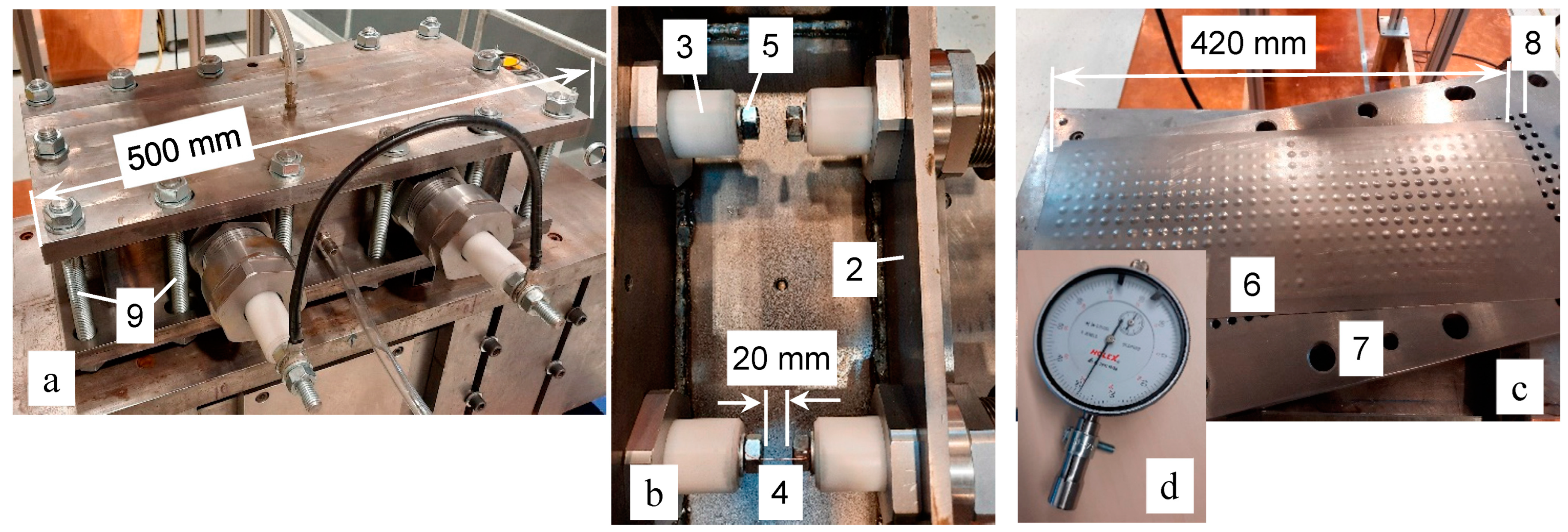
The experimental tooling was designed and produced according to the formulated scientific objectives (Figure 1). Since the tooling is not intended for sheet forming, the simple design of a box-type discharge chamber (2) was selected, with a flat top plate and straight side walls, as this is easy and cheap to manufacture (Figure 2). All four electrodes (3) were of the insulated type in order to permit the sequential connection of spark gaps. The insulator material is polyoxymethylene, which is easy to machine and strong enough for investigation purposes. The electrically conductive rods are carbon-steel studs with an M12 thread. This permits external cable connections and the reliable fixation of wires inside the chamber (ref. Figure 2).
The electrodes are connected to a pulse current generator of type SSG-0620FS (Poynting GmbH, Dortmund, Germany) [33]. The selected charge parameters are: charge voltage U0 = 20 kV, capacitance C = 15 µF and charge energy W0 = 3 kJ.
The transmitting medium (tap water) was supplied through the nipple in the lower point of the discharge chamber, and air evacuation was via the nipple in the top plate of the chamber (see Figure 2).
The measurements of pressure fields were to be performed with a multipoint membrane pressure gauge. In line with this aim, the bottom plate attached to the discharge chamber was designed as a body gauge plate with 396 holes of 6 mm diameter located in the nodes of a 12 × 12 mm square grid (ref. Figure 2). The measurement area corresponds approximately to the size of the exhaust window of the discharge chamber, which is 400 × 150 mm. The 0.5 mm sheets of DC01 steel [34,35] were used for the function of a metallic membrane that registered the peak pressure values of shock waves at 396 points.
The selection of the multipoint membrane method for the pressure-field measurements is justified by the capabilities of this method: a detailed map of the pressure distribution, easy use, easy processing of the measurement results, and a low cost by comparison to other methods.
The assembling and clamping of the experimental and measurement tooling are performed using 14 M16 studs in plain carbon steel. The tooling stack includes the discharge chamber (2), the metallic membrane (6), and the gauge body plate (7) (ref. Figure 1).
The discharges were initiated by Cu-ETP electrotechnical copper wires (CW004A/2.0060), which were 0.4 mm in diameter [36]. The length of the straight wires is 20 mm, as dictated by the geometrical configuration of the discharge system. The position of the wires was not axisymmetric relative to the electrode axes. The wires were displaced in the direction of the pressure gauge by a value equal to half the dimension of the threaded nut (19/2 = 9.5 mm). The distance between the wires (4) and the metallic membrane (6) is thus 40.5 mm (see Figure 1). Based on the experience of previous investigations [11,12,13,14,15,16,17], the authors decided to use copper wires for the purposes of stabilizing breakdowns in the two spark gaps, reducing pre-breakdown losses and their influence on test results, and specifying straight and equivalent discharge channel configurations in the test series that would ensure the reliability and repeatability of test results.
The quantity of discharges was limited to three tests due to the high repeatability of the pressure fields generated under the specified conditions.

2.2. Processing of Measurement Results

The multipoint membrane pressure gauge provides information on pressure values at 396 points located in the nodes of the 12 × 12 mm square grid. Each point (the hole axis in the gauge body) has coordinates (xi, yi). The line of holes along coordinate x starts at the point at 8 mm and finishes at 382 mm (33 points in each line). The column of holes along coordinate y starts at the point at 9 mm and finishes at 141 mm (12 points in each column). The pressure gauge can therefore be taken as a coordinate matrix (12 × 33) with 12 lines and 33 columns, which is convenient for processing the measurement results. The 17th column is on the middle line of the loaded zone (coordinate x = 200 mm) between the axes of the electrode pairs. The middle line across the axes of the electrode pairs has the coordinate y = 75 mm and is located between the 6th and 7th lines of holes (ref. Figure 1).
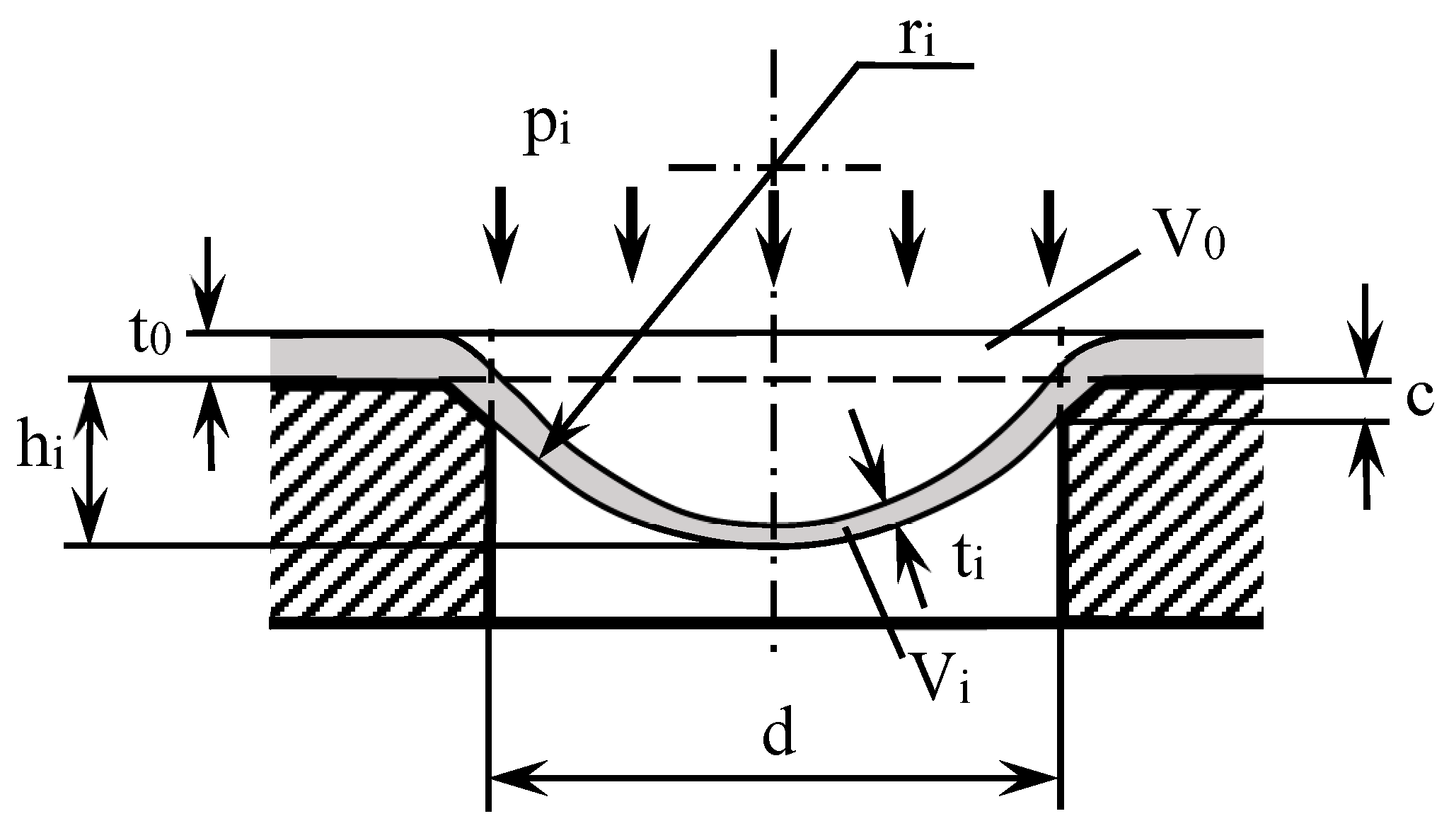
The membrane method of pressure measurements is based on the correlation between the membrane’s plastic deformation value at the location of the hole and the pressure value applied to this segment of the membrane. The plastic deformation of the membrane is estimated with the membrane deflection value—the height of the dimple hi (Figure 3). The heights measured with a dial indicator (ref. Figure 2d) are in the range hi = 0.02…0.92 mm on three samples. Each hi value is allocated to the definite (xi, yi) coordinates. The measurement tables are not shown here on account of their high volumes.
The impulse pressure value pi at the i-point can be calculated with the Laplace formula for spherical shell segments as a function of the radius ri of a formed dimple
p i   = 2 σ sdi   t i r i   ,
where ti is thickness of membrane after plastic deformation and σsdi is the flow stress at which impulse plastic deformation occurs.
This formula can be applied for the successive analysis with several assumptions. Laplace considered it a momentless shell. However, with the membrane deforming into a hole, a bending moment arises. Chamfer c of the membrane thickness value (0.5 mm) (ref. Figure 3) is implemented in each hole in order to reduce the magnitude of the bending moment. The assumption of a momentless shell (membrane) is therefore adopted.
The pressure field in the area around the gauge hole is taken to be locally homogeneous, that is, distributed smoothly without ruptures. The pressure distribution between neighbouring holes (local areas) is also assumed to be homogeneous and smooth.
In the real impulse-loading process, the membrane registers different maximum pressure values for different points on a measurement area, which appear at different points in time. However, in this study, it is assumed that certain maximum pressure values in all the measured points (holes) appear at the same point in time. The characteristic duration of the pressure pulse is much longer than the duration of membrane plastic deformation [27]. Other effects, such as springback and high-rate deformation, are considered further on in the text in relation to elastic strains and the dynamic coefficient.
The real shape of the dimple is more a combination of a truncated cone and a sphere segment, but it is not exactly spherical, as is shown by a great deal of research, including [37]. In this study, however, it is assumed that the shape of the dimple is spherical with a radius of ri. The radius is determined from the geometrical relationships (ref. Figure 3), taking the diameter of the hole d and the value of the membrane deflection hi
r i = d   2 + 4 h i 2 8 h i   .
A further assumption relates to the membrane thickness after deformation ti. This depends on the membrane deflection value hi and is non-uniformly distributed along the section curve (ref. Figure 3). In this analysis, it is assumed that the thickness value is constant and uniformly distributed along the spherical segment. In this case, the mean thickness value ti can be calculated from the condition of equal volumes of the membrane segment after (sphere segment) and before (disc of d diameter) deformation Vi = V0
t i = t 0 d   2 d   2 + 4 h i 2   .
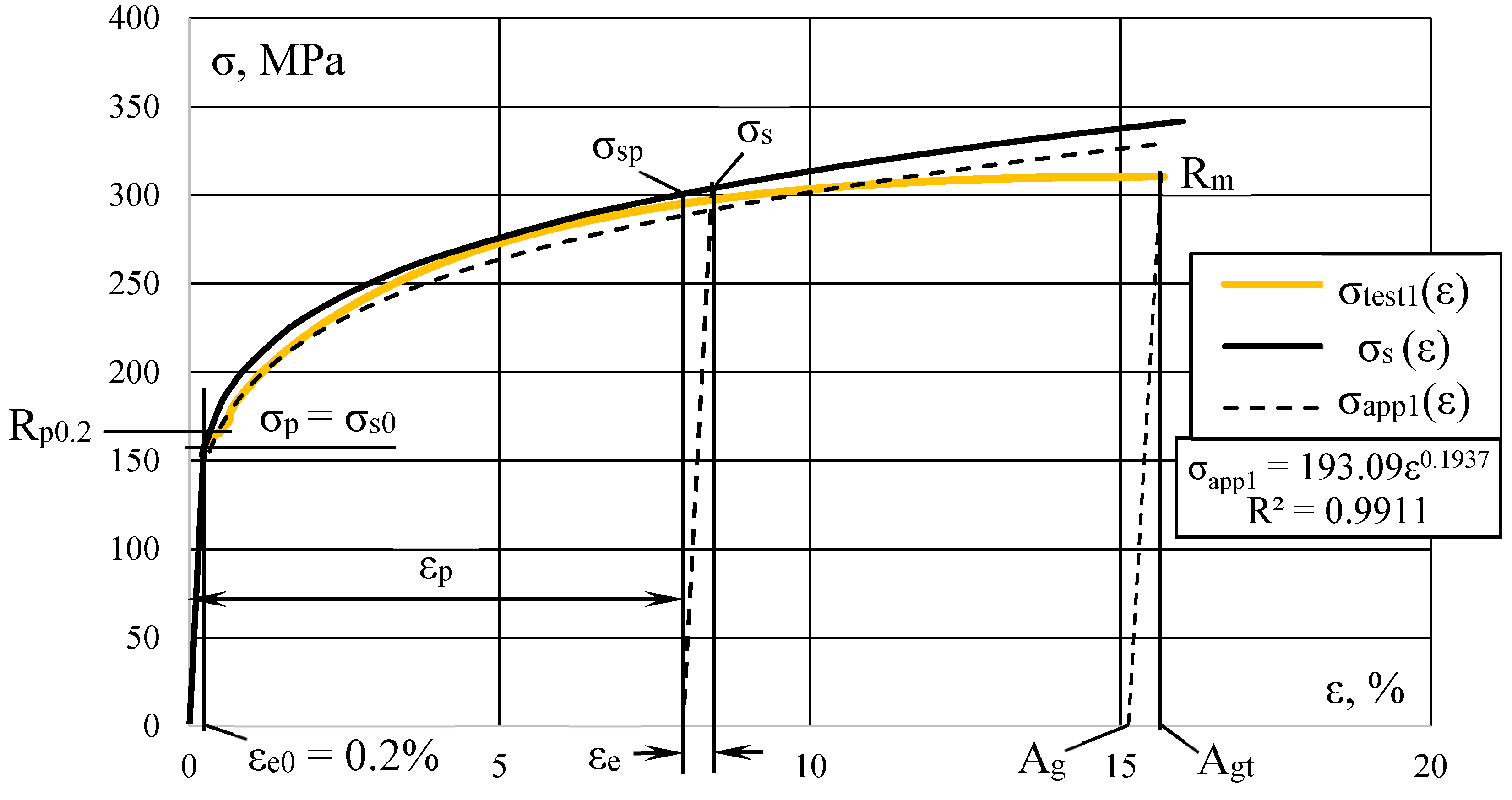
The flow stress σsi is more complicated in nature: it involves the strengthening of a material with increasing plastic deformation under a static load and the specific behavior of a material under impact (dynamic) loads. In order to obtain precise information on the strengthening effects, tensile tests under static conditions were conducted with the membrane material (Figure 4). As per ISO 6892-1:2019 [38], the dog-bone samples (a0 = 0.5 mm, b0 = 20.1 mm, and l0 = 80 mm) were cut in the rolling direction (5 pieces) and transverse direction (5 pieces). For the force-controlled tensile test, use was made of a test control II tensile testing machine from Zwick/Roell with a test speed control based on stress speeds in conformity with ISO 6892-1:2019 procedure B. The main parameters were processed, and the average values were calculated. In this study, the first important assumption is made: it is stated that the flow stress σs under biaxial deformation conditions (membrane deformation) equals the flow stress under uniaxial deformation for the same strain value ε. Tests adopting a biaxial approach can be conducted to obtain more precise information on material properties [37,39,40], but this solution would not improve accuracy to any notable extent [41].
The determinations of the analytical dependency between stress σs and strain ε values are considered below. Metallic membranes are usually subject to plastic deformation at flow stresses σs in a range extending from their yield limit to their tensile strength. The approximation was therefore only applied to this segment of the test curves: from the proof strength Rp0.2 at a plastic extension of Ae = 0.2% to the tensile strength Rm at a plastic extension of Ag at maximum force (the symbols are from the ISO 6892-1:2019 standard [38] in relation to the test data). The mean value of the proof strength is Rp0.2 = 172 MPa, with individual values for 10 tests in a range of 160 MPa to 176 MPa, and the mean tensile strength is Rm = 323 MPa (311…331 MPa). The curve σtest1(ε) for the single test with Rp0.2 = 160 MPa and Rm = 311 MPa (with the smallest values) is depicted in Figure 4 as an example of approximation σapp1(ε) with an exponential function and avoiding overlap with the general approximation curve.
The general approximation function (curve σs(ε) in Figure 4) has different values for the coefficient and exponent; these are calculated as mean values from ten sets of test data. Extrapolation of the general approximation curve made it possible to determine the proportional limit σp = 153.49 MPa at the limit elastic deformation εe0 = 0.2% calculated as a mean value from ten sets of test data (the coincidence with plastic extension of 0.2% for Rp0.2 is occasional). The DC01 steel along the straight segment added to the general approximation curve with stresses from 0 to σp and elastic strains from 0 to εe0 (see Figure 4) obeys Hooke’s law σ = mE·ε, where mE is the modulus of elasticity.
The approximation with an exponential function revealed good correlation with the experimental data (see Figure 4). It shows smaller values in the middle segment and larger values along the segment near Rm by comparison to the test data curve σtest1(ε). The diagram in Figure 4 shows the engineering stresses and strains. At low deformations, the engineering and true stresses almost coincide (as do the engineering and true strains ε) but, at the segment near the tensile strength Rm, the true stresses become noticeably larger than the engineering ones. The selected exponential function is thus closer to the true stresses.
The approximation function should include not only plastic deformation εp but also elastic deformation εe (ref. Figure 4), because the real flow stress in the membrane material at the moment of loading is determined by the total deformation
ε = εp + εe.
Here, component εe determines a springback effect, namely a reduction in the dimple shape and height hi after the action of the impulse pressure pi has ended. Previous investigations [10,27,28,29,30,31] did not include this effect in their analysis.
The approximation function should thus take the following form
σ s = K   ( ε p + ε e ) n ,
where K and n are the coefficients of the approximation function.
The resultant approximation function for flow stress σs (see the σs(ε) curve in Figure 4) is based on the results of ten tests for DC01 steel and was defined with the mean value of the coefficient of determination R2 = 0.9912 as
σ s = 205.928 ( ε p + ε e ) 0.1826 .
An analysis of the initial straight segments of test diagrams showed that the limit elastic deformation averages εe0 = 0.2% for DC01 steel with a plastic deformation of εp = 0. Taking formula (6), this corresponds to the flow stress value σs0 = 153.49 MPa (coinciding with the proportional limit σp) that agrees with the curves in Figure 4. This means that the membrane can deform elastically up to the limit εe0, and deflection hi would disappear when the impulse load pi fell to zero.
The value of the elastic deformation εe increases with the total deformation ε (ref. Figure 4). The respective elastic strain is therefore calculated from the formula
ε e = ε e 0 σ sp σ s 0   ,
where σsp is a flow stress calculated from Formula (6) with the measured value of the membrane deflection height hi that determines plastic deformation εp without elastic strain (εe = 0).
For the specific test parameters of DC01 material, the formula is
ε e = 0.2   σ sp 153.49 .
The mean plastic deformation (strain εp) is taken to be the ratio between the increment in the area of the spherical segment (Si—S0) and the area of the initial disc segment S0 [42] (ref. Figure 3).
ε p = S i S 0 S 0 100 % = ( 8 r i h i d   2 1 ) 100 % .
It is assumed here that plastic strain εp equals the relative reduction in the thickness of the membrane (t0 − ti)/t0 and that this reduction is evenly distributed along the spherical segment (though the maximum deformations and thinning are inherent to the central zone of the bulged membrane shown in Figure 3).
The formulas above are written for the deformation of membrane material under static pressure. The mechanical properties of metals, however, change greatly under impulse (dynamic) deformation conditions. Many researchers have reported on critical changes in stress-strain curves with the high strain rate deformation of different metals [43,44,45,46,47,48]. Electrohydraulic sheet forming is characterized by strain rates in the range 102–104 s−1 [43]. In many computational applications, it is proposed that the dynamic coefficient kd be used. This considers dynamic changes in the mechanical properties of a metal, but without detailed consideration of the high-rate mechanism of sheet metal deformation in its dynamic interaction with the transmitting medium. The dynamic coefficient is specified as the ratio of yield limits or ultimate strengths obtained under conditions of dynamic σsd and static σs loading:
k d = σ sd σ s   .
On the basis of their test results and also using the results of other researchers, Mazurovsky and Siziov [41] worked out an exponential function for approximating a decreasing dependency between the dynamic coefficient kd and flow stress value σs under static conditions for different metallic materials
k d = 3.006   e 0.0013 σ s ,
where e is a base of the natural logarithm and σs is in MPa.
This approximation formula correlates well with the results of other scientists [44,45,46,47,48]. It is revealed that the yield limit increases in a larger proportion than the tensile strength under the condition of dynamic (high strain rate) deformation. Therefore, in the reported range kd = 1.1–4.0 [43], the smaller kd values are related to higher flow stresses and the larger kd values to lower ones. In contrast to previous work [10], the proposed approach considers the large increases in metal flow stresses with high-rate deformation.
The dynamic coefficient thus allows for obtaining values that are close to the real flow stresses that appear in each membrane dimple upon impulse loading and deformation
σ sd = k d   K   ( ε p + ε e ) n ,
σ sd = k d   205.928   ( ε p + ε e ) 0.1826 .
For greater accuracy, it is recommended that the high-rate deformation tests be conducted with a specific material and that the dynamic coefficient be determined more precisely, giving consideration to sheet thickness and anisotropy [39].
The above formulas and simplified method were developed using many assumptions, thus giving values with a degree of error. This method can, however, be useful for qualitative analyses of pressure fields and, to some extent, for quantitative estimations. It ensures a higher accuracy for higher pressures with correspondingly greater deflections hi and a lower accuracy for small hi values due to the bigger relative error of the measuring device and the approximation error. The computation results thus showed that small plastic deformations occur at stresses even lower than the proportional limit σp determined for uniaxial tensile conditions. In strict consideration, the bulk (three-dimensional) deformation task ought to be solved for each dimple, taking into account the ratio of hole dimensions and membrane thickness. However, the solution to such a complex problem would not add greatly to the accuracy and would require a long time and large resources. The acceptance of a number of assumptions made it possible to simplify the processing algorithm and achieve a result with relatively good accuracy.
The accuracy of the method and pressure fields can be further improved with measurements of the impulse pressure curves employing other methods, such as measurements using piezoelectric sensors [18,19,20,21,22,23] at one or several points to determine the peak pressure of the shock wave. The correction coefficient is then calculated as the ratio between the peak pressure and the membrane-registered pressure value and applied to all the points of the pressure gauge.
If the pressure value were to be too low to cause only elastic deformation, the membrane would show zero pressure. On the other hand, if the pressure value were to be too high, it would fracture the membrane. When the hole diameter in the pressure gauge is small, the membrane only registers the shock wave pressure [49]. With a larger hole diameter, a membrane can register the summarized pressure of the shock wave, the hydraulic flow, and the quasi-static pressure of the gas-vapor bubble. The selection of an appropriate hole diameter and the material and thickness of the membrane are performed on the basis of the scientific tasks involved in an investigation.
According to the described procedure, measurements of the dimple heights hi were first made on three test membranes with the dial indicator equipped with an adaptor for the 6-mm dimples (ref. Figure 2d). These initial measuring data were processed in Microsoft Excel to calculate the values ri, εpi, σspi, εei, σsi, kdi, σsdi and pi and obtain three tables (xi, yi, pi) for plotting the pressure maps based on 396 points.
From the measured points, the maximum pressure values are selected for the left pmaxL and right pmaxR halves of the loaded area.
The mean maximum pressure values are calculated for the left and right halves of the three membranes
p maxLM = 1 3 j = 1 3 p maxLj ,   p maxRM = 1 3 j = 1 3 p maxRj .
The mean maximum pressure value is calculated for the whole loaded area
p maxM = 1 6 k = 1 6 p maxk .
Relative deviation of the maximum pressure value relative to the mean maximum pressure value
Δ p ¯ maxk = p maxk   p maxM p maxM 100 %   .
Further, the mean pressure values are calculated for each i-point in the three membranes
p mi = 1 3 j = 1 3 p ij .
Estimation of relative deviation at each i-point of the considered pressure field (j-membrane)
Δ p ¯ ij = p ij   p mi p mi 100 %   .
Mean relative deviation for each i-point in the j-membrane
Δ p ¯ mi = 1 3 j = 1 3 Δ p ¯ ij .
Mean pressure values are calculated for the j-membrane and for three membranes
p mj = 1 396 I = 1 396 p ij   ,   p m = 1 3 j = 1 3 p mj .
Mean relative deviation for the considered pressure field (j-membrane) from the mean value pm
Δ p ¯ j = p mj p m p m 100 %   .
These parameters will indicate the stability and repeatability of the pressure fields.
The purpose of this investigation is to determine the equilibrium of energies evolved in the two spark gaps through the equilibrium of the pressure fields and the forces generated by these pressure fields under the left and right spark gaps. It is therefore necessary to calculate the forces on the left (FL) and right (FR) halves of the loaded area. For this purpose, the mean pressure values are calculated for the left and right halves and then multiplied by the corresponding areas (SL = SR = S/2):
  • mean pressure value on the left half-area with the point coordinates at intervals x = 0–200 mm and y = 0–150 mm in the j-membrane
    p mLj = 1 198   i = 1 198 p ij ;
  • mean pressure value on the right half-area with the point coordinates at intervals x = 200–400 mm and y = 0–150 mm in the j-membrane
    p mRj = 1 198 i = 199 396 p ij ;
  • left-hand FL, right-hand FR and total F forces
    FL = pmL × SL; FR = pmR × SR; F = pm × S = FL + FR.
Two portions of force (left and right) are calculated as a percentage relative to the total force (100%)
F ¯ L = F L F F 100 % ;     F ¯ R = F R F F 100 % .
Pressure fields are plotted in MATLAB by MathWorks, Inc. for submitting the results and analysis.

3. Results

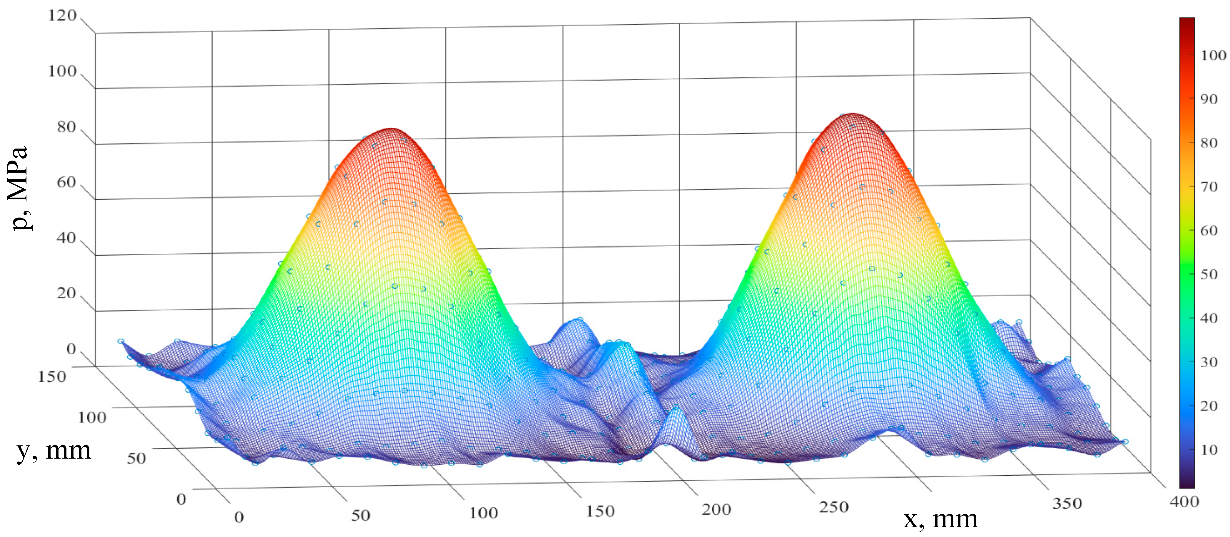
The experimental data of all three tests was processed, and different graphs were plotted for visualization of the test results. For illustration purposes only, the graphs based on the mean pressure values (xi, yi, pmi) are shown here (Figure 5 and Figure 6).
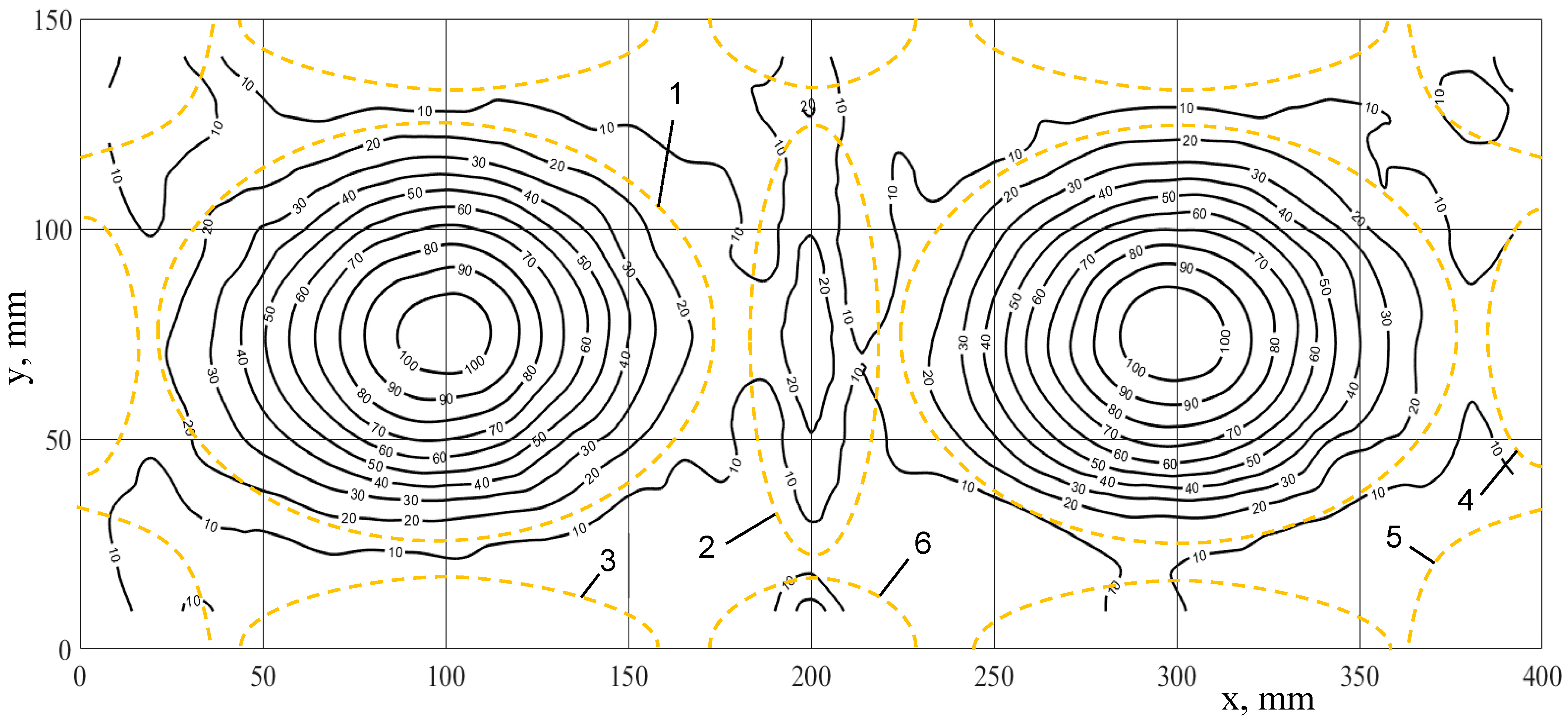
The maps clearly demonstrate three types of zones with increased pressure [10]: zones with loading mainly by direct shock waves (two areas); a zone with non-linear interaction of direct shock waves (a single zone); and zones with a concentration of direct and reflected shock waves (along the lateral walls of the discharge chamber). Table 1 shows the test statistics.

4. Discussion

The first-type zones are located directly under the two discharge channels with axis coordinates x = 100 mm and x = 300 mm, respectively. These two zones are characterized by the highest mean pressure values: left pmaxL = 103.451 MPa and right pmaxR = 106.044 MPa, respectively (ref. Table 1).
The non-coincidence of the two maximum values can be explained by slight deviations in the positions and lengths of the wires, deviations in the hole and chamfer dimensions in the pressure gauge, the non-uniformity of the membrane material properties, and other random factors. The level of accuracy is, however, sufficiently high: for these mean data, the relative error is just 1.24%, and the maximum relative error for all three tests (six peaks) is just 7.62% (Table 1, Test No. 2, right-hand zone). It is also clear that the pressure of the direct shock wave decreases rapidly with a greater distance between the discharge channel and the considered point on the wall (membrane) (ref. Figure 5).
These two zones are the main loading zones due to the highest pressure values there. They demonstrate the most important result: they are approximately equal, highlighting the equal portions of energy evolved in the two discharge channels. This is also confirmed by the approximately equal mean pressure values for the left and right halves: pmL = 25.42 MPa (in the range 23.96–26.26 MPa for the three tests) and pmR = 24.33 MPa (in the range 21.92–26.46 MPa), respectively. The impulse forces created on the bottom surface in the left and right half-areas are nearly equal (ref. Table 1). It is clear that the mean left-hand force FL is slightly larger than the mean right-hand force FR, but the mean maximum pressure on the left half pmaxML is slightly smaller than the mean maximum pressure on the right half pmaxMR. Indeed, the right-hand peak looks slightly higher and narrower (ref. Figure 5), and the left-hand peak is lower and wider. These deviations in pressure and areas are due to deviations in the position and straightness of the wires. In a sufficiently large series of tests, the statistically determined parameters of the direct loading zones will be absolutely equal. However, even this small quantity of tests reveals good accuracy for the energy evolution in both the discharge channels and the equability of pressures and forces that can be used to develop new, reliable electrohydraulic technologies.
The isobars for the loading zones with direct shock waves are evidently oval and not precisely round (ref. Figure 6, pos. 1). This is explained by the value of the spark gaps, the position of the wires relative to the electrodes, the “shadowing” effect of the electrodes (reflection of shock waves in the volumes nearest to the discharge channels), and the interaction of shock waves in the working liquid volume and on the bottom flat surface (membrane).
The second zone type is a zone with the interaction of direct shock waves (ref. Figure 6, pos. 2) generated by the two discharge channels on the bottom flat membrane. It was earlier confirmed [8,9,10] with regard to EHF that the interaction of two shock waves is non-linear in nature. In the considered case, when the shock waves are almost equal and simultaneous, the interaction effects appear in the volume between the two discharge channels. On the flat wall (membrane), these effects result in a zone of increased pressure. Due to the geometrical symmetry and the simultaneous explosion of the two wires, the interaction zone is located symmetrically between the electrodes, with the middle line coinciding with the middle line of the discharge chamber (coordinate x = 200 mm) (see Figure 5 and Figure 6). The maximum pressure in the interaction zone depends on the distance between the discharge channels, the work volume of the discharge chamber, and the distance between the discharge channels and the loaded surfaces. For a small distance and work volume, the resulting peak pressure in the interaction zone can exceed the peak pressure of the direct shock wave twofold [8,9]. In multi-electrode discharge systems with a large work volume [10], the resulting maximum pressure of two direct shock waves on the membrane surface in the interaction zone has a value equivalent to 0.82–2.85 of the peak pressure of the direct shock wave, depending on the orientation of the discharge channels. The non-linear effects are more pronounced than the arithmetic sum of the direct wave pressure (superposition principle) at the point considered. Previous tests [10] showed that the resulting pressure value can be up to 14 times higher than the arithmetic sum of the peak values of the two direct waves at the middle point.
In the considered tests, the maximum pressure (pmaxI = 27.41 MPa) calculated as a mean value from three tests is much smaller (3.82 times smaller) than the mean peak pressure in the direct-loaded zones. However, compared with the arithmetic sum of the direct wave pressures (5.25 MPa obtained by approximating the pressure curves of direct-loaded zones at the middle point), the maximum interaction pressure is 5.22 times higher, showing the result of non-linear effects. The geometric dimensions of the interaction zone can be estimated at approximately (40–50 mm) × 100 mm (ref. Figure 6).
The zones with a concentration of direct and reflected shock waves are located on the periphery of the loaded area (400 × 150 mm) along the lateral walls of the discharge chamber (ref. Figure 6). These are the results of reflection and the non-linear interaction of relatively weak shock waves. The largest widths of the concentration zones (up to 35–40 mm) are seen in the corners of the rectangular area (ref. Figure 6, pos. 5) due to multiple reflections from the walls with their 90° positioning. However, the widths are smaller along the straight lateral walls, at 20–30 mm. The peak pressure level in these zones does not exceed 20 MPa (ref. Figure 5). The concentration effects can be strengthened by locating rigid walls closer to the discharge channel and by profiling them, if the technology so requires.
In order to determine more precise dimensions for all the specified loading zones, it is recommended that an approximation be made of the experimental data.
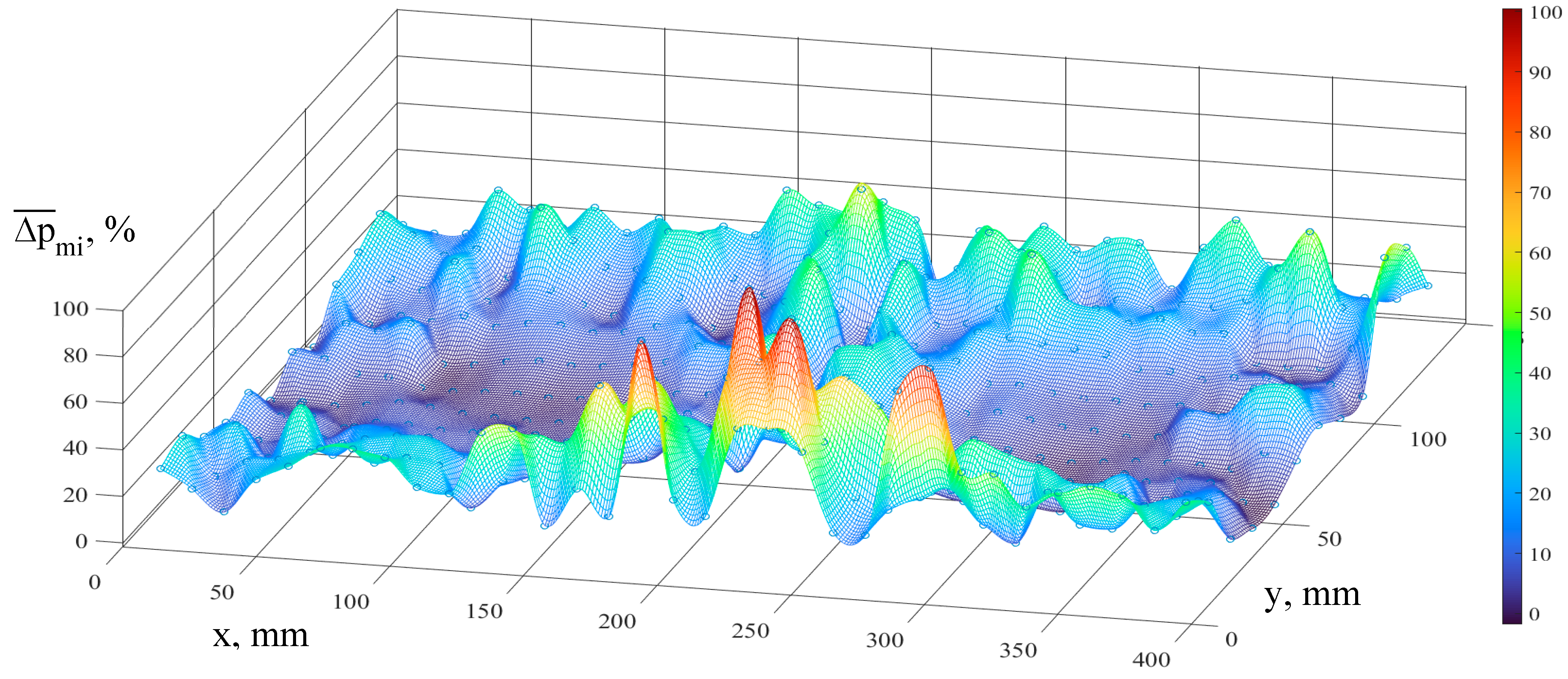
An estimation of the repeatability and stability of the test results is carried out by plotting the map of mean relative deviations from the mean pressure values at 396 measurement points (Figure 7).
The maximum deviation in the map is 98.26%, and, in general, the highest values are located along the periphery of the measuring area, that is, in the zones with the lowest absolute pressure values. This indicates that the non-linear interaction of direct and reflected shock waves in these zones is highly complicated and that a significant influence is exerted by deviations in other factors (the position of the wires, the parameters of the discharge plasma channels, the gas-vapor bubbles, etc.).
In all three tests, the mean deviations calculated from 396 points on the considered map were not very high: 20.25%, 21.41%, and 15.74%. All the deviation maps show the lowest level of deviation in the two zones of direct-wave loading (up to 15%) (ref. Figure 7). Alongside the maximum pressure values, this confirms the high stability of energy evolution in the two copper wires connected in sequence. Furthermore, the lower deviations are observed along the middle line (coordinate x = 200 mm), where the most intensive interaction of direct shock waves occurs.

5. Conclusions

The most important result of the tests involving the explosion of two wires connected in sequence is the equilibrium of the energies evolved in the two spark gaps. This conclusion is drawn on the basis of the approximate equality of the pressure fields on the left and right halves of the loaded area. The direct shock waves create zones with the most intensive loading. The explosion of two copper wires of 20 mm in length and 0.4 mm in diameter generates two zones with maximum pressure values in the range of 98.5–106.8 MPa.
These results provide a basis for the development of new electrohydraulic technologies with the application of two simultaneous discharges having equal energetic and pressure parameters.
The test results also made it possible to determine a zone with non-linear interaction of the direct shock waves in the middle section of the chamber, and zones with a concentration of direct and reflected waves along the rigid walls. Although their pressure parameters are not so high, these can be improved for certain specific and prospective technological purposes.
The method based on multipoint membrane pressure gauges has undergone further development, giving consideration to the actual plastic deformation that takes place in each dimple together with the elastic strains and dynamic properties of the metallic membrane. When combined with measurements using piezoelectric sensors, this can yield more valuable scientific results. A combination of this kind can improve accuracy when processing the membrane test results and can extend these more precise values over vast areas.
The detailed pressure maps obtained with the aid of multipoint membrane pressure gauges can be useful in combination with the EHF simulation programs [1,2,7,30,37] for the verification and optimization of both research methods.
Additionally, pressure maps are useful in practical terms: for analyzing the operation of discharge chambers of various designs, including multi-electrode blocks, and for optimizing their geometries and pressure loading fields (such as in [15,32]).
When planning the EHF operation for a specific sheet part, it is recommended that the same processing procedure be applied but that the Laplace formula for double-curvature shells be employed for the analysis of the part design so as to achieve the required pressure field. The available pressure fields are obtained with membrane pressure gauge measurements using a membrane made of the same sheet material as is intended for the part and using the selected discharge chamber. The parameters of the required and available fields will then have similar pressure values for comparison and improvement.
In order to determine the parameters of all the loading zones more precisely, it is necessary to perform an approximation of the experimental data. In addition, approximations are also useful for pressure map analyses, for revealing different phenomena, for studying the operation of different designs of discharge chamber, for planning electrohydraulic manufacturing operations, etc. Approximation dependencies can form the basis of an algorithm for determining the process parameters when a specific design of discharge chamber is employed.
The measuring method based on a multipoint membrane pressure gauge provided valuable scientific information in the form of detailed pressure maps, which were used for analysis and to draw conclusions. The data processing procedure was further developed so as to improve accuracy in the determination of pressure field parameters.
The authors’ future research will cover the development of an approximation method for pressure fields, experimental investigations into the electrical parameters of the two wire explosions, discharges in the two spark gaps connected in sequence but without wire initiation (high-voltage breakdown), discharges in two spark gaps connected in parallel, and also pressure field measurements employing a combination of a multipoint membrane gauge and piezoelectric sensors.

Author Contributions

Conceptualization, M.K. and W.H.; methodology, M.K.; investigation, M.K. and M.H.; writing—original draft preparation, M.K.; writing—review and editing, M.K. and M.H.; visualization, M.K. All authors have read and agreed to the published version of the manuscript.

Funding

The authors would like to thank the Phoenix Contact-Foundation for supporting this research.

Data Availability Statement

The data presented in this study are openly available in FigShare.com (accessed on 27 January 2023) at [https://doi.org/10.6084/m9.figshare.21982451.v1].

Conflicts of Interest

The authors declare no conflict of interest.

References

  1. Avrillaud, G.; Mazars, G.; Cantergiani, E.; Beguet, F.; Cuq-Lelandais, J.-P.; Deroy, J. Examples of How Increased Formability through High Strain Rates Can Be Used in Electro-Hydraulic Forming and Electromagnetic Forming Industrial Applications. J. Manuf. Mater. Process. 2021, 5, 96. [Google Scholar] [CrossRef]
  2. Mamutov, A.V.; Golovashchenko, S.F.; Bessonov, N.M.; Mamutov, V.S. Electrohydraulic Forming of Low Volume and Prototype Parts: Process Design and Practical Examples. J. Manuf. Mater. Process. 2021, 5, 47. [Google Scholar] [CrossRef]
  3. Cantergiani, E.; Atieh, S.; Léaux, F.; Perez Fontenla, A.T.; Prunet, S.; Dufay-Chanat, L.; Koettig, T.; Bertinelli, F.; Capatina, O.; Favre, G.; et al. Niobium superconducting rf cavity fabrication by electrohydraulic forming. Phys. Rev. Accel. Beams 2016, 19, 114703. [Google Scholar] [CrossRef]
  4. Naugolnykh, K.A.; Roy, N.A. Elektricheskie Razriady v Vode (Electrical Discharges in Water); Nauka: Moscow, Russia, 1971; p. 155. (In Russian) [Google Scholar]
  5. Deroy, J.; Claverie, A.; Avrillaud, G.; Boustie, M.; Mazanchenko, E.; Assous, D.; Chuvatin, A. Optical diagnostics for high power pulsed underwater electrical discharge characterization. J. Phys. Conf. Ser. 2014, 500, 142010. [Google Scholar] [CrossRef]
  6. Barbashova, G.A.; Shomko, V.V. Cyclicity effect of the electrical energy input in a channel of the underwater spark discharge. Surf. Eng. Appl. Electrochem. 2007, 43, 110–115. [Google Scholar] [CrossRef]
  7. Mamutov, A.V.; Golovashchenko, S.F.; Mamutov, V.S.; Bonnen, J.J.F. Modeling of electrohydraulic forming of sheet metal parts. J. Mater. Process. Technol. 2015, 219, 84–100. [Google Scholar] [CrossRef]
  8. Surkaev, A.L.; Kul’kov, V.G.; Talyzov, G.N. Experimental Investigation of the Interaction of Two Acoustic Shock Waves. Tech. Phys. Lett. 2001, 27, 487–488. [Google Scholar] [CrossRef]
  9. Surkaev, A.L. Investigations of High-Energy Impulse Processes in Condensed Media Based on Electric Explosion of Wires; Abstract of Dissertation for Dr. of Eng.; Volgograd State Technical University: Volgograd, Russia, 2018; p. 32. [Google Scholar]
  10. Knyazyev, M.K. Investigations, Development and Implementation of Manufacturing Processes of Electrohydraulic Forming with Application of Multi-Electrode Discharge Chambers; Dissertation for Candidate of Eng. Sciences; KhAI: Kharkov, Ukraine, 1995; p. 223. [Google Scholar]
  11. Shi, H.; Yin, G.; Li, X.; Wu, J.; Murphy, A.B.; Zhang, Y.; Qiu, A. Electrical wire explosion as a source of underwater shock waves. J. Phys. D Appl. Phys. 2021, 54, 403001. [Google Scholar] [CrossRef]
  12. Krivitskii, E.V. Dynamics of Electric Explosion in Liquids; Naukova Dumka: Kiev, Ukraine, 1983. [Google Scholar]
  13. Khainatskii, S. Conditions for realization of an optimum regime of the electric explosion of conductors in liquid media. Tech. Phys. Lett. 2009, 35, 299–301. [Google Scholar] [CrossRef]
  14. Homberg, W.; Beerwald, C.; Pröbsting, A. Investigation of the Electrohydraulic Forming Process with respect to the Design of Sharp Edged Contours. In Proceedings of the 4th International Conference on High Speed Forming, Columbus, OH, USA, 9–10 March 2010; pp. 58–64. [Google Scholar]
  15. Eguia, I.; Jose, J.S.; Knyazyev, M.; Zhovnovatyuk, Y. Pressure Field Stabilisation in High-Voltage Underwater Pulsed Metal Forming Using Wire-Initiated Discharges. Key Eng. Mater. 2011, 473, 965–972. [Google Scholar] [CrossRef]
  16. Rososhek, A.; Nouzman, D.; Krasik, Y.E. Addressing the symmetry of a converging cylindrical shock wave in water close to implosion. Appl. Phys. Lett. 2021, 118, 174103. [Google Scholar] [CrossRef]
  17. Maler, D.; Kozlov, M.; Efimov, S.; Krasik, Y.E. Supersonic jet generation by underwater sub-microsecond electrical explosions of wire arrays. Phys. Plasmas 2022, 29, 032705. [Google Scholar] [CrossRef]
  18. Amer, E.; Wozniak, M.; Jönsson, G.; Arrhén, F. Evaluation of Shock Tube Retrofitted with Fast-Opening Valve for Dynamic Pressure Calibration. Sensors 2021, 21, 4470. [Google Scholar] [CrossRef]
  19. Available online: https://www.drurylandetheatre.com/si-702s-ultra-high-pressure-transducer/ (accessed on 3 January 2023).
  20. Available online: https://mueller-instruments.de/en/pressure-measurement/mueller-platte-needle-probe/ (accessed on 3 January 2023).
  21. Wen, D.Y.; Lin, Q.W. Electrical response of PVDF film under shock loading. Chin. J. High Press. Phys. 2000, 14, 291–297. [Google Scholar]
  22. Wang, A.; Chen, C.; Qian, J.; Yang, F.; Wang, L.; Zhang, M. Enhanced Electrical Properties of PVDF Thin Film by Addition of NaCl by Near-Electric-Field 3D Printing. J. Electron. Mater. 2021, 50, 4781–4786. [Google Scholar] [CrossRef]
  23. Tartière, J.; Arrigoni, M.; Nême, A.; Groeneveld, H.; Van Der Veen, S. PVDF Based Pressure Sensor for the Characterisation of the Mechanical Loading during High Explosive Hydro Forming of Metal Plates. Sensors 2021, 21, 4429. [Google Scholar] [CrossRef]
  24. Cong, J.; Jing, J.; Chen, C.; Dai, Z. Development of a PVDF Sensor Array for Measurement of the Dynamic Pressure Field of the Blade Tip in an Axial Flow Compressor. Sensors 2019, 19, 1404. [Google Scholar] [CrossRef]
  25. Available online: https://mueller-instruments.de/en/electronic-pressure-films (accessed on 3 January 2023).
  26. Available online: https://mueller-instruments.de/en/pressure-indicating-film-prescale (accessed on 3 January 2023).
  27. Vagin, V.A.; Zdor, G.N.; Mamutov, V.S. Metody Issledovaniya Vysokoskorostnogo Deformirovaniya Metallov (Methods of Research of High-Speed Deformation of Metals); Navuka i tekhnika: Minsk, Belarus, 1990; p. 208. [Google Scholar]
  28. Cole, R.H. Underwater Explosions; Princeton University Press: Princeton, NJ, USA, 1948. [Google Scholar]
  29. Homberg, W.; Djakow, E.; Damerow, O. Process reliability and reproducibility of pneumomechanical and electrohydraulic forming processes. In Proceedings of the 6th International Conference on High Speed Forming, Daejeon, Korea, 27–29 March 2014; pp. 217–228. [Google Scholar]
  30. Djakow, E.; Homberg, W.; Tabakajew, D. Combined working media-based forming on a pneumo-mechanical high speed forming machine. In Proceedings of the ICHSF 2016, Dortmund, Germany, 27–28 April 2016; pp. 47–58. [Google Scholar]
  31. Beerwald, C.; Beerwald, M.; Dirksen, U.; Henselek, A. Impulse Hydroforming Method for Very Thin Sheets from Metallic or Hybrid Materials. In Proceedings of the 4th International Conference on High Speed Forming, Columbus, OH, USA, 9–10 March 2010; pp. 150–158. [Google Scholar]
  32. Vohnout, V.J.; Fenton, G.; Daehn, G.S. Pressure heterogeneity in small displacement electrohydraulic forming processes. In Proceedings of the 4th International Conference on High Speed Forming, Columbus, OH, USA, 9–10 March 2010; pp. 65–74. [Google Scholar]
  33. Bedienungsanleitung SSG-0620FS, Version 1.02; letzte Änderung: 04/2012; Poynting GmbH: Dortmund, Germany, 2012.
  34. ASTM A1008/A1008M; Standard Specification for Steel, Sheet, Cold-Rolled, Carbon, Structural, High-Strength Low-Alloy, High-Strength Low-Alloy with Improved Formability, Solution Hardened, and Bake Hardenable. ASTM International: West Conshohocken, PA, USA, 2021.
  35. DIN EN 10130; Cold Rolled Low Carbon Steel Flat Products for Cold Forming. Technical Delivery Conditions. DIN: Berlin, Germany, 2007.
  36. DIN EN 13601; Copper and Copper Alloys—Copper Rod, Bar and Wire for General Electrical Purposes. DIN: Berlin, Germany, 2021.
  37. Yu, H.; Zheng, Q. Forming limit diagram of DP600 steel sheets during electrohydraulic forming. Int. J. Adv. Manuf. Technol. 2019, 104, 743–756. [Google Scholar] [CrossRef]
  38. EN ISO 6892-1; Metallic Materials—Tensile Testing Part 1: Method of Test at Room Temperature. International Organization for Standardization: Geneva, Switzerland, 2019; p. 78.
  39. Farahnak, P.; Urbánek, M.; Konopík, P.; Džugan, J. Influence of thickness reduction on forming limits of mild steel DC01. Int. J. Mater. Form. 2020, 13, 371–381. [Google Scholar] [CrossRef]
  40. EN ISO 16808:2022; Metallic Materials. Sheet and Strip. Determination of Biaxial Stress-Strain Curve by Means of Bulge Test with Optical Measuring Systems. International Organization for Standardization: Geneva, Switzerland, 2022; p. 24.
  41. Wang, H.; Xu, T.; Shou, B. Determination of Material Strengths by Hydraulic Bulge Test. Materials 2017, 10, 23. [Google Scholar] [CrossRef]
  42. Knyazyev, M.K.; Zhovnovatuk, Y.S. Measurements of Pressure Fields with Multi-Point Membrane Gauges at Electrohydraulic Forming. In Proceedings of the 4th International Conference on High Speed Forming, Columbus, OH, USA, 9–10 March 2010; pp. 75–82. [Google Scholar]
  43. Mazurovsky, B.Y.; Siziov, A.N. Elektrogidravlicheskiy Effect v Listovoi Shtampovke (Electrohydraulic Effect in Sheet Forming); Naukova Dumka: Kiev, Ukraine, 1983; p. 192. [Google Scholar]
  44. Das, A. High Strain Rate Deformation Behaviour of Automotive Grade Steels. Ph.D. Dissertation, Indian Institute of Technology, Kharagpur, India, 2019; p. 288. [Google Scholar]
  45. Okitsu, Y.; Tsuji, N. Effect of Ferrite Grain Size on Dynamic Tensile Properties of Ultrafine Grained Low Carbon Steels with Various Chemical Compositions. Mater. Trans. 2014, 55, 78–84. [Google Scholar] [CrossRef] [Green Version]
  46. Mihalikova, M.; Girman, V.; Liskova, A. Static and dynamic tensile characteristics of S420 and IF steel sheets. Mater. Technol. 2016, 50, 543–546. [Google Scholar] [CrossRef]
  47. Xiong, R.-G.; Fu, R.-Y.; Yu, S.; Qian, L.; Wei, X.-C.; Lin, L. Tensile Properties of TWIP Steel at High Strain Rate. J. Iron Steel Res. Int. 2009, 16, 81–86. [Google Scholar] [CrossRef]
  48. Beynon, N.D.; Jones, T.B.; Fourlaris, G. Effect of high strain rate deformation on microstructure of strip steels tested under dynamic tensile conditions. Mater. Sci. Technol. 2005, 21, 103–112. [Google Scholar] [CrossRef]
  49. Knyazyev, M.K.; Chebanov, Y.I. Multi-Electrode Discharge Blocks for Electrohydraulic Forming and their Capabilities. East. Eur. J. Enterp. Technol. 2004, 3, 13–20. [Google Scholar]
Figure 1. Schematic diagram of the experimental setup: 1—pulse generator; 2—discharge chamber filled with water; 3—isolated electrode; 4—wire; 5—nut; 6—metallic membrane; 7—multipoint pressure-gauge body; 8—hole of 6 mm diameter; 9—stud.
Jmmp 07 00040 g001
Figure 2. General view of the experimental tooling (a), discharge chamber with electrodes and wire fixation (b), multipoint pressure gauge body and metallic membrane after impulse loading (c), dial indicator with adaptor for 6 mm dimples (d); Numbering is the same as in Figure 1.
Jmmp 07 00040 g002
Figure 3. Schematic diagram of membrane deformation into the hole of the pressure gauge.
Jmmp 07 00040 g003
Figure 4. Approximation of test engineering stress-strain curves: σtest1(ε)—segment of representative curve based on single test data; σapp1(ε)—approximation function for single representative test; R2—coefficient of determination; σs(ε)—curve of general approximation function based on mean values of 10 tests; Rp0.2—proof strength at plastic extension 0.2%; Rm—tensile strength at plastic Ag and total Agt extensions; σp—stress limit of proportionality at elastic strain εe0 = 0.2%; εp and εe—elastic and plastic components of total strain (deformation) for flow stress value σs.
Jmmp 07 00040 g004
Figure 5. Three-dimensional representation of the pressure field generated by the simultaneous explosion of the two wires plotted from the mean test values.
Jmmp 07 00040 g005
Figure 6. Contour representation of the pressure field generated by the simultaneous explosion of the two wires plotted from the mean test values. The digits on the isobars are in MPa. Contours of the revealed loading zones with: 1—direct shock wave (2 zones); 2—non-linear interaction of direct shock waves; 3, 4, 5, 6—concentration of direct and reflected shock waves along rigid walls (12 zones).
Jmmp 07 00040 g006
Figure 7. Map of mean relative deviations Δ p ¯ mi from mean pressure values pmi at measured points.
Jmmp 07 00040 g007
Table 1. Pressure and force parameters for two zones loaded by direct shock waves.
Test No.pmaxl, MPapmaxr, MPa Δ p ¯ maxL , % Δ p ¯ maxR , %F, MNFL, MN F L ¯   , %FR, MN F R ¯ , %
1103.81798.524–0.89–5.941.3770.71952.220.65847.78
2100.669112.731–3.89+7.621.5750.78149.600.79450.40
3105.868106.878+1.07+2.031.5260.78851.640.73848.36
Mean values103.451106.044–1.24%+1.24%1.4920.762 0.730
pmaxM = 104.748 100% 51.1% 48.9%
Disclaimer/Publisher’s Note: The statements, opinions and data contained in all publications are solely those of the individual author(s) and contributor(s) and not of MDPI and/or the editor(s). MDPI and/or the editor(s) disclaim responsibility for any injury to people or property resulting from any ideas, methods, instructions or products referred to in the content.