Article

Ultrasonic Welding of Additively Manufactured PEEK and Carbon-Fiber-Reinforced PEEK with Integrated Energy Directors

1
Walter-and-Ingeborg-Herrmann Chair for Power Ultrasonics and Engineering of Functional Materials, Department of Sustainable Systems Engineering (INATECH), University of Freiburg, 79110 Freiburg, Germany
2
Freiburg Materials Research Center (FMF), 79110 Freiburg, Germany
3
Fraunhofer Institute for High-Speed Dynamics (EMI), 79110 Freiburg, Germany
*
Author to whom correspondence should be addressed.
J. Manuf. Mater. Process. 2023, 7(1), 2; https://doi.org/10.3390/jmmp7010002
Submission received: 28 November 2022 / Revised: 19 December 2022 / Accepted: 19 December 2022 / Published: 23 December 2022

Abstract

:
The thermoplastic polymer polyether ether ketone (PEEK) offers thermal and mechanical properties comparable to thermosetting polymers, while also being thermally re-processable and recyclable as well as compatible with fused filament fabrication (FFF). In this study, the feasibility of joining additively manufactured PEEK in pure and short carbon-fiber-reinforced form (CF-PEEK) is investigated. Coupon-level samples for both materials were fabricated using FFF with tailored integrated welding surfaces in the form of two different energy director (ED) shapes and joined through ultrasonic polymer welding. Using an energy-driven joining process, the two materials were systematically investigated with different welding parameters, such as welding force, oscillation amplitude and welding power, against the resulting weld quality. The strengths of the welded bonds were characterized using lap-shear tests and benchmarked against the monotonic properties of single 3D-printed samples, yielding ultimate lap-shear forces of 2.17 k N and 1.97 k N and tensile strengths of 3.24 M Pa and 3.79 M Pa for PEEK and CF-PEEK, respectively. The weld surfaces were microscopically imaged to characterize the failure behaviors of joints welded using different welding parameters. Samples welded with optimized welding parameters exhibited failures outside the welded region, indicating a higher weld-strength compared to that of the bulk. This study lays the foundation for using ultrasonic welding as a glue-free method to join 3D-printed high-performance thermoplastics to manufacture large load-bearing, as well as non-load-bearing, structures, while minimizing the time and cost limitations of FFF as a fabrication process.

1. Introduction

Under the umbrella of additive manufacturing (AM) technologies, fused filament fabrication (FFF) has grown to become the most widely used method to fabricate structures using thermoplastic polymers. Recent developments in this 3D-printing technology have allowed high-performance thermoplastics, both amorphous, such as polyetherimide (PEI), as well as members of the semi-crystalline polyaryl ether ketone (PAEK) family of polymers, such as polyether ether ketone (PEEK), to join the growing portfolio of FFF-printable materials [1,2,3,4]. These thermoplastics possess maximum service temperatures comparable to those of thermosetting materials, opening up the possibility of replacing them as the matrix material for fiber-reinforced composites [5] for applications requiring high service-temperatures, or as the reinforcing material for composites with engineering thermoplastics as the matrix material [6]. The added advantage of using thermoplastic polymers in fiber-reinforced composites lies in their more sustainable thermal recyclability options [7,8,9], which is a crucial topic of research going forward towards sustainable composite materials within a circular materials economy.
The move to component-level and mass-manufacturing using FFF of 3D-printing of thermoplastics is hindered by two inherent disadvantages of AM-technologies. The first is in the layer-on-layer nature of the fabricated structure, leading to a lower surface quality, as well as weak inter-layer adhesion and inferior part mechanical properties compared to conventional plastic fabrication techniques, such as injection-molding [10]. The second drawback lies in the time and cost-risks involved in the mass manufacture of large components; that is, the larger the part size, the longer the printing time and the higher the chance, that the 3D-print will fail. These failures can arise due to the material’s thermofluidic response during the printing process, the quality of thermal isolation of the FFF-machine, or, most frequently, to a lack of build-plate adhesion under part of the component foot-print. For larger components, a slight debonding of the first print-layer can grow as more layers are successively printed due to the torque applied by the moving print-head as it extrudes and places material forming the next layer. This can quickly lead to a complete print-failure and loss of material, time and energy.
To help offset the inherent disadvantages of FFF, ultrasonic welding of thermoplastics can be used as a bonding technique to assemble components from additively manufactured parts. Ultrasonic welding (USW) has been shown to be a quick and reliable method for joining metal to metal [11,12], metal to composite [13,14,15], as well as composite to composite [16,17,18,19] parts. USW involves rapid heating and cooling of the weld interface under static pressure. For thermoplastics, the thermodynamic mechanism of USW involves melt initiation at the weld-interface through surface friction, followed by viscoelastic heating as the temperature of the weld interface exceeds the glass-transition temperature of the adherends [20,21]. The use of USW for fiber-reinforced thermoplastic and thermosetting composites has been demonstrated through the use of interface structures called energy directors (ED) [22,23,24,25]. EDs in the form of thermoplastic meshes are conventionally used as the interfacial layer between the adherends and are responsible for melt initiation at the weld interface, which then spreads into the adherend surfaces and, after cooling under pressure, leads to a welded joint.
By combining fused filament fabrication and ultrasonic welding, the two aforementioned disadvantages of FFF can be greatly improved upon. Ultrasonic treatment of additively manufactured parts, termed ultrasonic strengthening or ultrasonic consolidation, has been shown to improve their mechanical properties [26,27,28] by improving the inter-layer adhesion through cross-melting down the part thickness. Using the advantage of free-form fabrication of FFF, smaller parts with integrated energy directors can be manufactured more quickly and, hence, reliably, followed by assembly and upscaling to component-level through USW. Moreover, USW can also be used to debond the joints in event of failure, potentially enabling a quick and reliable on-site replacement of defective parts, rather than replacement of the whole component. The discarded parts can be re-processed by shredding and re-extrusion of FFF-compatible filaments, thus closing the materials circularity loop.
This study looks at the feasibility of using ultrasonic welding as the joining method for additively manufactured PEEK and short carbon-fiber-reinforced PEEK (CF-PEEK), as the first step in investigating the feasibility of a materials circularity strategy for high-performance thermoplastics and thermoplastic composites. First, 3D-printed PEEK and CF-PEEK tensile samples were tested under monotonic conditions and compared to their respective datasheet values to understand the loss in tensile strength and Young’s modulus due to additive manufacturing. Adherends for ultrasonic welding were then 3D-printed with integrated energy directors in two different shapes and joined using an ultrasonic plastic welding machine under a variety of US-welding conditions. The joined specimens were tested for their mechanical properties using lap-shear stress tests and the failure surfaces were compared using optical microscopy. The results obtained through this work lay the foundation for further investigations into combining FFF and USW for high-performance thermoplastics with integrated EDs, leading towards a comprehensive and robust circularity concept for these versatile and cost-intensive materials.

2. Materials and Methods

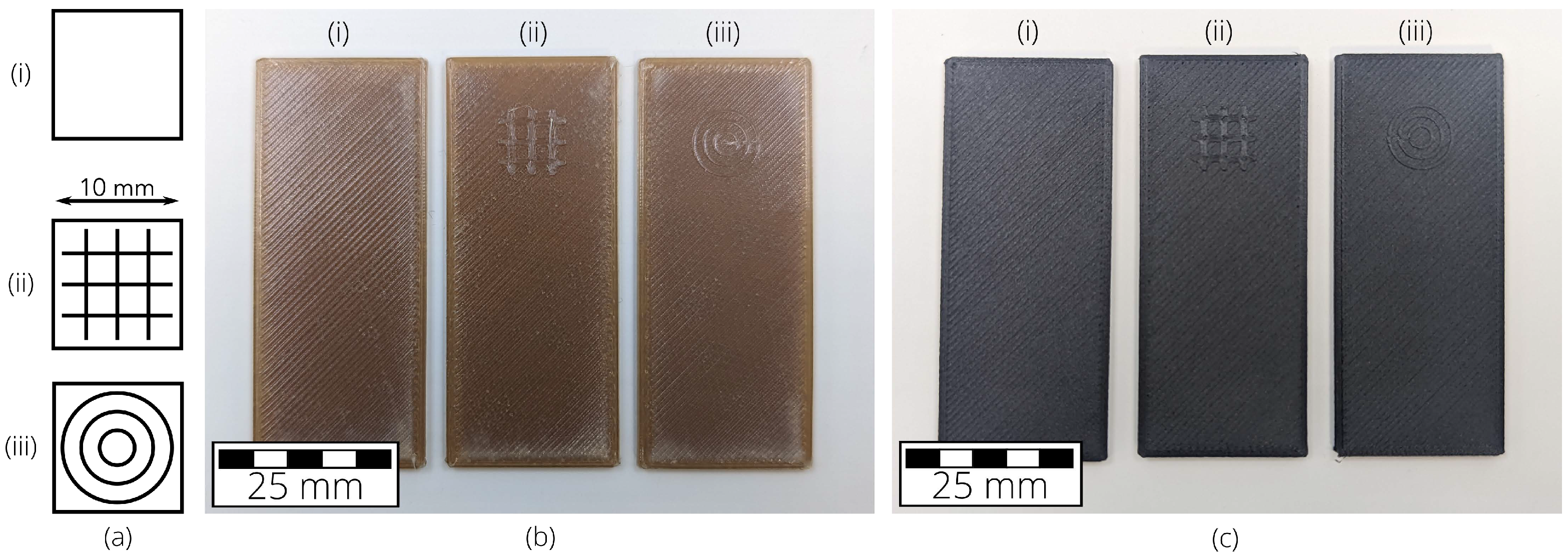
2.1. Sample Design and Fabrication

All samples investigated were manufactured using the Intamsys FunMat Pro 410 FFF-printer (Intamsys Technology GmbH, Ostfildern, Germany), using PEEK and 10 wt . % short carbon-fiber-filled PEEK (CF-PEEK) filaments from the same manufacturer. The filaments were first dried in the integrated drying chamber of the printer for at least 48 h at 70 C before being printed. The print-parameters used are listed in Table 1.
Samples for tensile testing were fabricated with outer dimensions of L × B × H of 160 × 20 × 2 mm 3 with a radial central region ( ϕ = 139 mm), resulting in a middle cross-section of 10 mm 2 . The ultrasonic welding samples were manufactured as coupons measuring L × B × H of 60 × 25 × 2 mm 3 . The average void volume in the 3D-printed PEEK and CF-PEEK samples were measured at 11 vol . % and 21 vol . % , respectively. Figure 1 shows images of the 3D-printed tensile samples. No mechanical or thermal post-processing was performed on the samples after fabrication.
Ultrasonic welding samples were fabricated as coupons with integrated mesh-shaped and circular energy directors with heights of 0.2 mm, and line-widths of 2 mm and 1 mm, leading to volumes of 10.2   m m 3 and 6.1   m m 3 , respectively. Figure 2 shows the USW sample images. Samples without EDs were additionally fabricated and used as the lower adherend during the welding experiments.

2.2. Ultrasonic Welding Equipment

The additively manufactured PEEK and CF-PEEK coupons were joined using a Herrmann Ultrasonics HiQ Vario 20/6200 polymer ultrasonic welding machine (Herrmann Ultraschalltechnik GmbH & Co. KG, Karlsbad, Germany), shown in Figure 3a. A polymer-welding sonotrode with a flat circular welding surface ( ϕ = 20 mm, nominal frequency 20 k Hz , rated max amplitude 45 μ m ) was used for all welding experiments (Figure 3b). The samples were clamped using lever-clamps on to a milled aluminum anvil with guiding blocks to ensure that the specimens remained parallel to each other with a constant overlap area while welding (Figure 3c). All welding experiments were carried out with the welding energy as the driving parameter. Preliminary experiments were performed to optimize the three driven parameters to the oscillatory system by benchmarking the input welding force and amplitude against the quality and accuracy of the observed welding parameters, after which the static welding force, sonotrode amplitude and the post-weld hold-time were kept constant. Table 2 shows the chosen welding parameters after completion of the preliminary tests.

2.3. Mechanical Characterization

The virgin and welded samples were mechanically characterized in a Zwick/Roell Z020 universal testing machine (Zwick/Roell, Ulm, Germany). Monotonic tests were carried out on the tensile samples with a clip-on strain gauge (max. range 25 mm) to determine their elastic-plastic behavior. The ultrasonic welded sample pairs were characterized using lap-shear strength (LSS) tests to determine the ultrasonic bond strength. For this, the upper and lower clamps of the testing machine were positioned such that the pulling force would apply as a shear force on the weld surface. Both test types were performed at a pull-rate of 1 mm/ min , with measurement recording starting at a force of 50 N and stopped when a force drop of 80% of the measured maximum force (Fmax) was detected. Figure 4 shows the tensile and welded samples during mechanical testing.

2.4. Fracture Surface Analysis

Post-failure optical characterization was carried out using a Zeiss Smartzoom 5 optical microscope (Carl Zeiss AG, Oberkochen, Germany) to investigate the failure behavior of the welded samples.

3. Results and Discussion

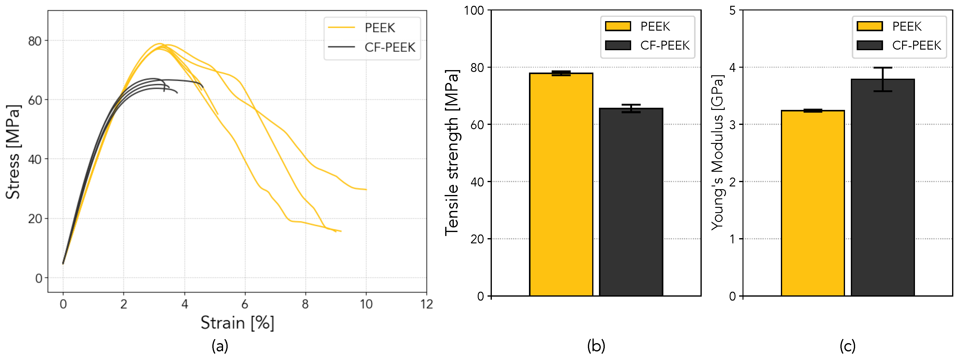
3.1. Monotonic Tests

Monotonic tests were carried out on the 3D-printed PEEK and CF-PEEK tensile samples (see Section 2.1) to provide a benchmark for the mechanical properties of the welded samples. Figure 5 summarizes the results observed.
Figure 5a compares the stress-strain behavior of the PEEK and CF-PEEK tensile samples. The CF-PEEK samples exhibited a lower ultimate tensile strength as well as a shorter plastic deformation region. An average tensile strength (Figure 5b) of ( 78.0 ± 0.7 ) M Pa was observed for the PEEK samples, compared to ( 66.0 ± 1.3 )   M Pa for the CF-PEEK specimens. A significantly higher Young’s modulus of ( 3.79 ± 0.21 )   G Pa was observed for the CF-PEEK samples (Figure 5c) compared to PEEK at ( 3.24 ± 0.02 )   G Pa . The measured Young’s modulus for PEEK lies within 5% below those of the values provided in the manufacturer’s data-sheet and can be interpreted as a direct result of the layer-by-layer manufacturing method of the samples.

3.2. Ultrasonic Welding Parameter Optimization

Preliminary experiments were carried out to determine the optimal static welding force and amplitude for the 3D-printed adherends before the energy-driven welding experiments could be realized. For this, amplitudes of 30 μ m and 40 μ m , as well as static weld forces between 100 N and 700 N , were tested against the weld strength at a weld-energy of 400 J . Figure 6 shows the influence of the amplitude and the ED shape on the US-welding behavior of both materials.
The power-time characteristics shown in Figure 6 show the expected shorter welding times when using a 40 μ m oscillation amplitude. For PEEK samples welded at 400 J (Figure 6a), the welding time for the circular ED was 18% shorter compared to the mesh variant. For CF-PEEK (Figure 6b), no significant difference was found at 40 μ m amplitude; however, the weld duration was 60% shorter for the mesh-shaped ED at 30 μ m . This difference could be a result of the smaller volume of the circular ED, leading to quicker melt generation and energy transfer.
The samples welded using amplitudes of 30 μ m and 40 μ m were tested for their weld strength using lap-shear tests. Figure 7 shows the effect of the welding amplitude on the mechanical characteristics.
Figure 7 compares the mechanical behavior of the PEEK and CF-PEEK samples welded with 400 J under a static force of 200 N at amplitudes of 30 and 40 μ m . The power-time curves (Figure 7a) show a slower dissipation of energy for the CF-PEEK samples with mesh-shaped energy directors. For both PEEK and CF-PEEK, the joints formed at 40 μ m amplitude showed higher failure forces, as seen in Figure 7b. This was observed to be true for both materials, irrespective of the energy director shape. All further experiments were carried out with a target oscillation amplitude of 40 μ m .
The static welding force was the next parameter to be set during the preliminary experiments. Figure 8 shows the effect of the static welding force on the amplitude-time behavior for a pair of PEEK adherends. The weld behavior under a static force of 250 N and 400 N was observed to be significantly different, keeping the adherends, as well as all other welding parameters, identical.
Two representative welding behaviors for PEEK adherends are shown in Figure 8. Under a static welding force of 250 N (Figure 8a), the observed fluctuations from the target amplitude of 40 μ m were significantly lower than that in Figure 8b, with a static force of 400 N . This change can be attributed to changes in the response of the whole resonance system under the increased force, from the piezo-actuators in the welding machine initiating the vibrations, down to the anvil holding the adherends. At higher static forces, the control system of the ultrasonic welder was unable to stabilize at the target amplitude, which can be seen in the power curve (red) in Figure 8. As a consequence, the amplitude and frequency behavior showed significant variations over the duration of the weld. For the PEEK samples welded with static forces above 350 N , these fluctuations were seen to exceed the maximum-rated amplitude of the sonotrode (45 μ m ) and were deemed to be potentially damaging to the ultrasonic welder. The CF-PEEK adherends showed similar welding behavior under increased static forces greater than 300 N . For adherends without energy directors, these fluctuations were more pronounced at all tested static forces. This is a result of the larger initial area of contact between the adherends at the start of the welding process in the absence of an ED, leading to an arbitrary melt generation in the sample overlap region and, therefore, larger variations in the resonance system through the course of the welding process. Based on these observations, a static force of 250 N was chosen as the standard for further experiments with both EDs.
After the completion of the preliminary experiments, a weld-force of 250 N and an amplitude of 40 μ m was used for further experiments to investigate the effect of the integrated energy directors on the weld quality and strength. These energy-driven welding experiments were carried out with the optimized weld-parameters (see Section 2).

3.3. Lap-Shear Strength Tests

PEEK and CF-PEEK samples welded under a static force of 250 N at a 40 μ m amplitude were tested for their joint strengths against the applied weld-energies of 300, 400 and 500 J using lap-shear tests. Five samples were tested for each parameter set, leading to 60 experiments in total. Figure 9 summarizes these results.
Figure 9a shows the mechanical behavior of PEEK and CF-PEEK adherends welded at 500 J at a 40 μ m amplitude under a static force of 250 N . The PEEK adherends showed an average of 10% higher failure forces, as well as a more pronounced plastic deformation region. The CF-PEEK samples exhibited a steeper gradient in the linear deformation region, suggesting a higher elastic modulus, which was also confirmed during tensile tests (see Figure 5). Figure 9b summarizes the average failure forces for all energy-driven welding experiments using the selected amplitude and static force. The highest ultimate lap-shear forces were observed at 500 J for both materials. The comparatively inferior force and deformation characteristics of CF-PEEK can be attributed to the short carbon-fiber reinforcements used, which hindered the polymer’s deformation under loading and also resulted in comparatively stiffer behavior in the linear region.

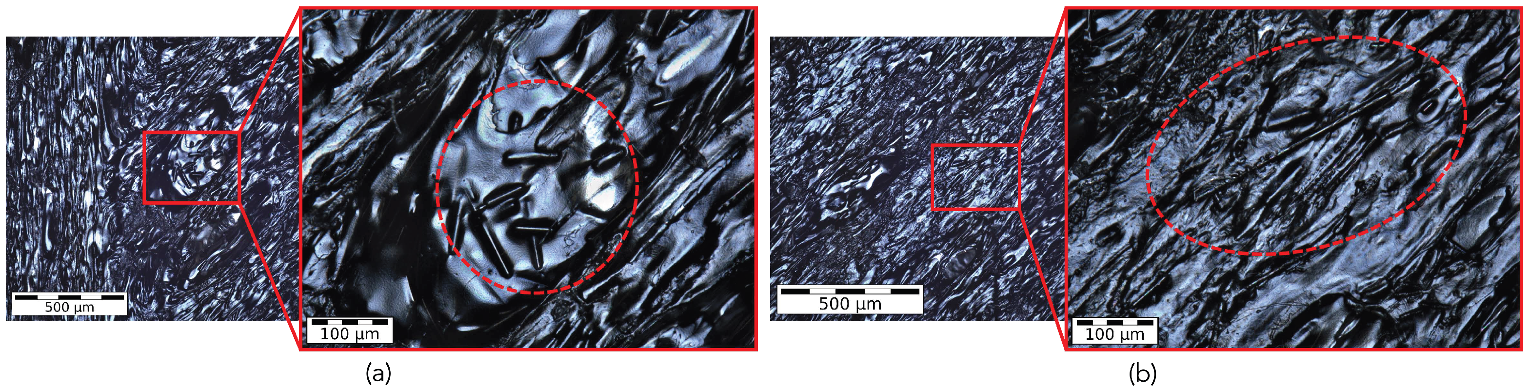
3.4. Microscopy and Failure Behavior

The failure behavior and surfaces of the failed samples from lap-shear testing were imaged using optical microscopy to investigate the differences in failure mechanisms between the two materials as well as the influence of the ED shape. Representative microscopic images are shown in Figure 10.
Figure 10 shows the failure behavior for the two different materials and energy directors. PEEK samples showed a larger plastic deformation region before failure regardless of the failure behavior (see Figure 9a). For either ED shape, the CF-PEEK failure boundary can be seen to be more jagged, which is a result of the higher brittleness of this material arising due to the short-fiber reinforcements. Due to a lack of information on the average fiber length from the filament manufacturer, a set of microscopic images of the filament were analyzed to yield the upper and lower fiber lengths of 250 μ m and 50 μ m , respectively. Representative images are shown in Figure 11. A narrower fiber-length distribution in the filament can help in increasing the precision of the results observed.
The failure behavior of both materials was found to be heavily influenced by the ED shape. Welds performed with mesh-shaped EDs (Figure 10a,b) were seen to fail at the weld boundary with the failure surface approximately perpendicular to the pulling force. In contrast, welds with circular EDs (Figure 10c,d) did not fail at the weld-site, but, instead, at one of the inter-layer boundaries in the bulk of the 3D-printed samples. This is a good indication of the superior quality of the circular EDs, as the molten region under the ED did not fail before the bulk material, and is supported by the results from mechanical testing (see Figure 9b).

4. Conclusions and Outlook

This pilot study looked at the feasibility of using ultrasonic welding as the joining method for additively manufactured high-performance thermoplastics with integrated energy directors. PEEK and CF-PEEK adherends were 3D-printed on the coupon level, each with two different ED shapes, and were joined reliably using polymer ultrasonic welding at 20 k Hz . For comparison, tensile samples were 3D-printed and tested against their datasheet values. USW parameters, including static welding force and amplitude were individually investigated and optimized against the weld strength and vibrational behavior during welding and were seen to have a significant effect on the weld quality and welding parameter precision as well as the resulting joint strength. Adherends without energy directors were seen to have highly fluctuating amplitudes through the course of the welding process. This was also true for welds carried out at higher static forces. From the preliminary experiments, a static welding force of 250 N and a vibrational amplitude of 40 μ m were selected.
Energy-driven welding experiments were performed for both materials and with the two ED shapes at 300, 400 and 500 J and subsequently tested for their weld strength through lap-shear testing. PEEK adherends showed superior weld strengths and deformation characteristics for each parameter set compared to CF-PEEK. The melt-behavior of the two EDs led to vastly different failure behaviors, which can be attributed to both the volume and the shape of the EDs. Adherends with circular energy directors showed higher failure forces compared to their mesh-shaped counterparts. Microscopy and failure surface analysis showed significantly different failure behaviors between the two ED shapes. Adherends with circular EDs did not fail at the weld-site, resulting in the peeling-off of the 3D-printed layer from the sample bulk.
This study lays the foundation for further investigations into the bonding of 3D-printed high-performance thermoplastics and thermoplastic composites using ultrasonic welding. Future investigations can examine the temperature and melting behavior of the EDs during the welding through contact and infra-red measurements. Another important aspect is the behavior of multiple welded joints on a single pair of adherends in a multi-spot welding configuration, followed by the continuous welding of these materials. The effect of the rapid heating and cooling occurring during FFF and USW on the semi-crystallinity of PEEK and the resulting mechanical properties are also an important topic for further research, in particular, for the development of a materials circularity concept for additively manufactured thermoplastics and thermoplastic composites.

Author Contributions

Conceptualization, B.K. and F.B.; methodology, B.K. and M.F.R.; software, B.K. and M.F.R.; validation, B.K. and M.F.R.; formal analysis, B.K. and M.F.R.; investigation, B.K. and M.F.R.; resources, F.B.; data curation, M.F.R.; writing—original draft preparation, B.K.; writing—review and editing, F.B.; visualization, B.K. and M.F.R.; supervision, B.K. and F.B.; project administration, B.K. and F.B. All authors have read and agreed to the published version of the manuscript.

Funding

This research received no external funding.

Data Availability Statement

Not applicable.

Acknowledgments

We would like to thank the Walter and Ingeborg Herrmann Foundation for the support of our ultrasonic welding research at INATECH.

Conflicts of Interest

The authors declare no conflict of interest.

Abbreviations

The following abbreviations are used in this manuscript:
AMAdditive manufacturing
CF-PEEKCarbon-fiber-reinforced polyether ether ketone
EDEnergy director
FFFFused filament fabrication
LSSLap-shear strength
PAEKPolyarylether ether ketone
PEEKPolyether ether ketone
PEIPolyetherimide
USWUltrasonic welding

References

  1. Dey, A.; Nanjin, I.; Eagle, R.; Yodo, N. A Review on Filament Materials for Fused Filament Fabrication. J. Manuf. Mater. Process. 2021, 5, 69. [Google Scholar] [CrossRef]
  2. Algarni, M.; Ghazali, S. Comparative study of the sensitivity of PLA, ABS, PEEK, and PETG’s mechanical properties to FDM printing process parameters. Crystals 2021, 11, 995. [Google Scholar] [CrossRef]
  3. El Magri, A.; Vanaei, S.; Vaudreuil, S. An overview on the influence of process parameters through the characteristic of 3D-printed PEEK and PEI parts. High Perform. Polym. 2021, 33, 862–880. [Google Scholar] [CrossRef]
  4. Zanjanijam, A.R.; Major, I.; Lyons, J.G.; Lafont, U.; Devine, D.M. Fused filament fabrication of PEEK: A review of process-structure-property relationships. Polymers 2020, 12, 1665. [Google Scholar] [CrossRef]
  5. Arif, M.F.; Alhashmi, H.; Varadarajan, K.M.; Koo, J.H.; Hart, A.J.; Kumar, S. Multifunctional performance of carbon nanotubes and graphene nanoplatelets reinforced PEEK composites enabled via FFF additive manufacturing. Compos. Part Eng. 2020, 184, 107625. [Google Scholar] [CrossRef]
  6. Palacios-Ibáñez, B.; Relinque, J.J.; Moreno-Sánchez, D.; de León, A.S.; Delgado, F.J.; Escobar-Galindo, R.; Molina, S.I. Synthesis and Characterisation of ASA-PEEK Composites for Fused Filament Fabrication. Polymers 2022, 14, 496. [Google Scholar] [CrossRef]
  7. Hartig, S.; Hildebrandt, L.; Fette, M.; Meyer, T.; Musienko, E.; Redlich, T.; Wulfsberg, J. Process parameter determination for small recycling plants for the production of filament for FFF printing using the Taguchi method. Prog. Addit. Manuf. 2021, 7, 87–97. [Google Scholar] [CrossRef]
  8. Reis, J.P.; de Moura, M.; Samborski, S. Thermoplastic composites and their promising applications in joining and repair composites structures: A review. Materials 2020, 13, 5832. [Google Scholar] [CrossRef]
  9. Kumar, R.; Singh, R.; Farina, I. On the 3D printing of recycled ABS, PLA and HIPS thermoplastics for structural applications. Psu Res. Rev. 2018, 2, 115–137. [Google Scholar] [CrossRef]
  10. Zandi, M.D.; Jerez-Mesa, R.; Lluma-Fuentes, J.; Jorba-Peiro, J.; Travieso-Rodriguez, J.A. Study of the manufacturing process effects of fused filament fabrication and injection molding on tensile properties of composite PLA-wood parts. Int. J. Adv. Manuf. Technol. 2020, 108, 1725–1735. [Google Scholar] [CrossRef]
  11. Becker, M.; Kuball, A.; Ghavimi, A.; Adam, B.; Busch, R.; Gallino, I.; Balle, F. Solid State Joining of a Cold Rolled Zr-Based Bulk Metallic Glass to a Wrought Aluminum Alloy by Power Ultrasonics. Materials 2022, 15, 7673. [Google Scholar] [CrossRef] [PubMed]
  12. Becker, M.; Balle, F. Multi-spot ultrasonic welding of aluminum to steel sheets: Process and fracture analysis. Metals 2021, 11, 779. [Google Scholar] [CrossRef]
  13. Liesegang, M.; Arweiler, S.; Beck, T.; Balle, F. Orbital ultrasonic welding of ti-fittings to cfrp-tubes. J. Manuf. Mater. Process. 2021, 5, 30. [Google Scholar] [CrossRef]
  14. Staab, F.; Balle, F. Fatigue and fracture of ultrasonically welded aluminum alloys to carbon fiber reinforced thermoplastics. Fatigue Fract. Eng. Mater. Struct. 2021, 45, 607–616. [Google Scholar] [CrossRef]
  15. Staab, F.; Balle, F. Ultrasonic torsion welding of ageing-resistant Al/CFRP joints: Properties, microstructure and joint formation. Ultrasonics 2019, 93, 139–144. [Google Scholar] [CrossRef]
  16. Li, W.; Frederick, H.; Palardy, G. Multifunctional films for thermoplastic composite joints: Ultrasonic welding and damage detection under tension loading. Compos. Part Appl. Sci. Manuf. 2021, 141, 106221. [Google Scholar] [CrossRef]
  17. Bhudolia, S.K.; Gohel, G.; Fai, L.K.; Barsotti, R.J. Investigation on ultrasonic welding attributes of novel carbon/Elium® composites. Materials 2020, 13, 1117. [Google Scholar] [CrossRef] [Green Version]
  18. Wang, K.; Shriver, D.; Li, Y.; Banu, M.; Hu, S.J.; Xiao, G.; Arinez, J.; Fan, H.T. Characterization of weld attributes in ultrasonic welding of short carbon fiber reinforced thermoplastic composites. J. Manuf. Process. 2017, 29, 124–132. [Google Scholar] [CrossRef]
  19. Korycki, A.; Garnier, C.; Bonmatin, M.; Laurent, E.; Chabert, F. Assembling of Carbon Fibre/PEEK Composites: Comparison of Ultrasonic, Induction, and Transmission Laser Welding. Materials 2022, 15, 6365. [Google Scholar] [CrossRef]
  20. Villegas, I.F. Ultrasonic Welding of Thermoplastic Composites. Front. Mater. 2019, 6, 291. [Google Scholar] [CrossRef]
  21. Benatar, A. Ultrasonic welding of plastics and polymeric composites. In Power Ultrasonics: Applications of High-Intensity Ultrasound; Elsevier Ltd.: Amsterdam, The Netherlands, 2015; Chapter 12; pp. 295–312. [Google Scholar] [CrossRef]
  22. Tsiangou, E.; Teixeira de Freitas, S.; Villegas, I.F.; Benedictus, R. Ultrasonic welding of epoxy- to polyetheretherketone- based composites: Investigation on the material of the energy director and the thickness of the coupling layer. J. Compos. Mater. 2020, 54, 3081–3098. [Google Scholar] [CrossRef] [Green Version]
  23. Tao, W.; Su, X.; Wang, H.; Zhang, Z.; Li, H.; Chen, J. Influence mechanism of welding time and energy director to the thermoplastic composite joints by ultrasonic welding. J. Manuf. Process. 2019, 37, 196–202. [Google Scholar] [CrossRef]
  24. Chuah, Y.K.; Chien, L.H.; Chang, B.C.; Liu, S.J. Effects of the shape of the energy director on far-field ultrasonic welding of thermoplastics. Polym. Eng. Sci. 2000, 40, 157–167. [Google Scholar] [CrossRef]
  25. Palardy, G.; Villegas, I.F. On the effect of flat energy directors thickness on heat generation during ultrasonic welding of thermoplastic composites. Compos. Interfaces 2017, 24, 203–214. [Google Scholar] [CrossRef] [Green Version]
  26. Wu, W.; Wang, H.; Wang, J.; Liu, Q.; Zhang, Z.; Li, K.; Gong, Y.; Zhao, J.; Ren, L.; Li, G. Hybrid Additive Manufacturing of Fused Filament Fabrication and Ultrasonic Consolidation. Polymers 2022, 14, 2385. [Google Scholar] [CrossRef]
  27. Tofangchi, A.; Han, P.; Izquierdo, J.; Iyengar, A.; Hsu, K. Effect of ultrasonic vibration on interlayer adhesion in Fused Filament Fabrication 3D printed ABS. Polymers 2019, 11, 315. [Google Scholar] [CrossRef] [PubMed] [Green Version]
  28. Li, G.; Zhao, J.; Jiang, J.; Jiang, H.; Wu, W.; Tang, M. Ultrasonic strengthening improves tensile mechanical performance of fused deposition modeling 3D printing. Int. J. Adv. Manuf. Technol. 2018, 96, 2747–2755. [Google Scholar] [CrossRef]
Figure 1. Images of the additively manufactured (above) PEEK and (below) CF-PEEK tensile samples.
Jmmp 07 00002 g001
Figure 2. (a) Schematic depictions of the three surface variants investigated for ultrasonic welding. (i) without an energy director (ED), (ii) with a mesh-shaped ED and (iii) with a circular ED. (b,c) show images of the PEEK and CF-PEEK USW samples with and without EDs, in order, respectively. Both ED variants were printed with a height of 0.2 and a maximum respective width or diameter of 10 mm.
Jmmp 07 00002 g002
Figure 3. (a) The ultrasonic welding setup used in this work. (b) The vibrating horn, or sonotrode, used to carry out all joining experiments. (c) PEEK samples during welding, clamped on to an aluminum anvil using lever-clamps. The front guides were removed for this image for sample visibility.
Jmmp 07 00002 g003
Figure 4. Images of (a) a tensile sample, with a clipped-on capacitive strain gauge, and (b) welded PEEK samples under lap-shear test conditions.
Jmmp 07 00002 g004
Figure 5. A comparison of (a) the stress-strain behavior, (b) the average tensile strengths and (c) the Young’s moduli measured for the PEEK and CF-PEEK tensile samples.
Jmmp 07 00002 g005
Figure 6. Representative power characteristics from the ultrasonic welding experiments with (a) PEEK and (b) CF-PEEK adherends at amplitudes of 30 and 40 μ m , each with (solid line) circular and (dotted line) mesh-shaped energy directors.
Jmmp 07 00002 g006
Figure 7. Representative mechanical characteristics from the ultrasonic welding experiments on the PEEK and CF-PEEK coupons at target amplitudes of 30 and 40 μ m . (a) The power-time behavior of the welds, and (b) the corresponding mechanical behavior of the joints under lap-shear loading. The dotted and solid curves shown represent welding amplitudes of 30 μ m and 40 μ m , respectively.
Jmmp 07 00002 g007
Figure 8. Representative curves from the ultrasonic welding tests on the PEEK coupons with identical welding parameters, except for the static welding force of (a) 250 N and (b) that of 400 N . The samples were welded together in both cases; however, the fluctuation from the target amplitude (blue) of 40 μ m was significantly higher for (b) over the weld duration. This additionally led to an oscillatory behavior of the input power (red) and the frequency (green).
Jmmp 07 00002 g008
Figure 9. (a) Results from the lap-shear tests for PEEK and CF-PEEK samples with circular energy directors welded at 500 J . (b) A summary of the ultimate shear forces observed during the lap-shear tests with circular and mesh-shaped energy directors, welded at 300, 400 and 500 J .
Jmmp 07 00002 g009
Figure 10. Microscopic images of the typical failure types and surfaces observed for PEEK and CF-PEEK USW samples with (a,b) mesh-shaped energy directors and (c,d) circular EDs, respectively.
Jmmp 07 00002 g010
Figure 11. Two examples of the observed differences in carbon-fiber length seen in the printed samples. (a) Fibers with a length of around 50 μ m and (b) with 250 μ m .
Jmmp 07 00002 g011
Table 1. 3D-print parameters for the PEEK and CF-PEEK samples.
Nozzle temperature390 C
Build-plate temperature135 C
Build-chamber temperature60 C
Filament drying/storage temperature70 C
Nozzle diameter 0.4 mm
Layer thickness 0.1 mm
Print speed30 mm/ s
Sample volume-fill100%
Number of shells2
Table 2. Ultrasonic welding parameters investigated for joining PEEK and CF-PEEK samples.
Welding energy300, 400, 500 J
Static welding force250 N
Amplitude of US-oscillation40 μ m
Hold-time3 s
Disclaimer/Publisher’s Note: The statements, opinions and data contained in all publications are solely those of the individual author(s) and contributor(s) and not of MDPI and/or the editor(s). MDPI and/or the editor(s) disclaim responsibility for any injury to people or property resulting from any ideas, methods, instructions or products referred to in the content.

