
Numerical Modeling of Titanium Alloy Ti10V2Fe3Al Milling Process

Institute for Machine Tools, University of Stuttgart, Holzgartenstraße 17, 70174 Stuttgart, Germany
*
Author to whom correspondence should be addressed.
J. Manuf. Mater. Process. 2023, 7(1), 1; https://doi.org/10.3390/jmmp7010001
Submission received: 29 November 2022
/
Revised: 18 December 2022
/
Accepted: 20 December 2022
/
Published: 22 December 2022
Abstract
:The simulation of material machining using finite element models is a powerful tool for the optimization of simulated processes and tools, as well as for the determination of cutting process characteristics that are difficult or practically impossible to determine by experiment. The paper presents results of the numerical simulation of the titanium alloy Ti10V2Fe3Al (Ti-1023). The behavior of the machined material was modeled with the Johnson–Cook constitutive equation, and its damage mechanism was modeled using the Cockcroft and Latham model. The parameters of the constitutive equation for machined material behavior and damage were determined using a DOE sensitivity analysis during orthogonal cutting. The values of the cutting force components, as well as the minimum and maximum chip thicknesses, were used as target functions for the DOE analysis. The generalized values of the constitutive equation parameters and the fracture stress values determined by the DOE analysis were calculated as the set intersection of individual multitude values of these parameters. The simulation results of the studied cutting processes showed an acceptable agreement with the experimental data when the cutting speed and tool feed changed significantly. The deviation in the simulated values of the cutting forces from their measured values ranged from about 10% to about 20%.
1. Introduction
The simulation of the machining process leads to a deeper understanding of the cutting process. It enables a better estimation of the events and physical conditions taking place in the primary, secondary, and tertiary deformation zones (e.g., stress distributions and local temperature gradients) than most measuring technology. Thus, complex correlations can be determined with the use of numerical simulations [1,2]. Furthermore, machining simulations reduce the number of experimental tests and machine operation times as well as material and very high prototyping costs. The simulation of machining has been performed intensively for over a decade with the increasing computing power. It requires specific material models and theoretical knowledge about machining mechanics and modeling approaches. Machining processes are characterized by constantly varying contact conditions, which continuously challenge the simulation technology.
The arrival of new numerical models in commercial simulation software has led to an increased number of alternatives for simulating processes. Mesh-based numerical methods, such as the finite element method (FEM), are very well-known alternatives for estimating the effect of process parameters in machining operations. In adequate combination with analytical and empirical approaches, the FEM turns out to be a reliable tool in metal cutting [3]. New numerical mesh-free methods require experience to precisely set-up simulation parameters and to deal with numerical implications and the resulting effects.
Using FE models of machining operations has been the subject of various studies [1,2,3]. Although machining processes with end tools, such as drilling and milling, account for 40–60% of all material removal processes and are, therefore, among the most used machining operations in modern manufacturing [4,5,6], there are few studies devoted to the spatial modeling of such cutting processes. This is mainly caused by the great amount of calculation time needed and the lack of reference guidelines in the model design. In this sense, Tiffe illustrated that most publications on the FEA of drilling do not give much detail about the model design [6]. Concerning the expenditure of time, Neugebauer et al. showed the time needed for a satisfactory 3D drilling simulation using the Deform SFTC software [4]. Without considering model corrections and optimizations, the final simulation in the publication required 50,000 calculation steps and three weeks of calculation time [1]. Such an expenditure of time makes a practicable study of the effects tough, considering the several possible process and simulation parameters that can be tested and optimized for a satisfactory machining simulation. Therefore, two-dimensional simulations and process simplifications of the cutting process have been preferred in the scientific literature [3]. Especially, drilling and milling operations require 3D simulations. In these operations, the material constantly moves along the tool’s main cutting edges from the smallest diameter to the largest diameter, which causes significant changes in the cutting speed. Due to these kinematics as well as the additional finishing at the lateral cutting edges of the tool, plane stress and strain conditions cannot be assumed. Risse stated that two-dimensional simulations of similar machining processes are no efficient alternative to analyzing the process [7]. AdvantEdge is an FE code based on an explicit time integration scheme, specifically designed for metal cutting and chip formation. Ma et al. designed three-dimensional FE models of drilling with this commercial software [8]. The workpiece material behavior of the aluminum alloy Al7050 was modeled by a power hardening law.
Numerical simulations for different types of milling processes have been the subject of many investigations, e.g., [9,10,11,12]. Modeling the spatial milling process was replaced in the early studies considering the orthogonal cutting process with the subsequent distribution of the 3D cutting process [13]. Thus, chip formation and determination of the cutting force during milling were simulated. Wu and Zhang proposed a three-dimensional finite-element milling model of titanium alloy Ti6Al4V developed in the Abaqus software environment [14]. They determined the parameters of the Johnson–Cook constitutive equation using a high-temperature split Hopkinson pressure bar test system at various temperatures, strains, and strain rates of the material to be machined. To determine the material damage criterion proposed by the Johnson-Cooke fracture model, data from the basic Recht study were used [15,16]. The authors used the Zorev model, which provides automatic determination of the friction state according to the contact stress in the simulation process, as a model of contact interaction between the tool and the machined material [17,18]. Determining the parameters of the constitutive equation when cutting titanium alloys has been discussed quite extensively in various studies. Several studies of the milling process have also been focused on this topic, e.g., [19,20,21]. Zhang et al. analyzed different parameter sets of the Johnson–Cook constitutive equation for milling titanium alloy Ti-6Al-4V with respect to different numerical simulation formulations [19]. As a result, recommendations were proposed for determining parameters of the machined material model. Sima and Özel analyzed the parameter sets of the constitutive equation for simulating the cutting of titanium alloy Ti-6Al-4V, as obtained by various authors [20]. The authors pointed out the importance of the modified model proposed by Calamaz et al. [22] to describe the cutting behavior of the machined material. In addition, the importance of flow softening phenomena during the crystal deformation of titanium alloy Ti-6Al-4V was highlighted, regardless of the FE software. Cheng and Outeiro developed a numerical model of orthogonal cutting for titanium alloy Ti-6Al-4V to determine the main characteristics of the cutting process and the physical–mechanical characteristics of the machined workpiece surface [21]. The contact interaction between tool and chip as well as between tool and workpiece was simulated using the Zorev model [17]. The numerical cutting model proposed by the authors provided a relatively good agreement between simulated and measured characteristics for different cutting conditions. The effect of different temperature-dependent flow softening conditions on the simulated characteristics for the orthogonal cutting of titanium alloy Ti6Al4V was presented in the paper by Karpat [23]. He proposed a description form of flow softening as a function of cutting temperature. This description was integrated into the material model. The application of such a material model form provided a good agreement between simulation results and experimental data of the cutting characteristics.
The influence of the cutting-edge rounding radius when milling grooves in titanium alloy was studied by Sui et al. [24]. The finite element cutting model used a modified Johnson–Cook constitutive equation considering the effect of recrystallization softening of the machined material. The influence of cutting modes, in particular, cutting speed, tool feed, and depth of cut, on the characteristics of the slot milling process in titanium alloy Ti-6Al-4V was researched in a study by Chen and colleagues [25]. Based on these studies, the authors proposed recommendations for selecting the optimal cutting modes. The commercial AdvantEdge program was used as the software environment. To effectively control the machining process, Daniyan et al. performed a numerical simulation and experimental confirmation of titanium alloy milling [26], using the ABAQUS software product. This approach ensured that machining errors are tracked, monitored, and controlled with real-time machining data. Cutting titanium alloy without cooling when machining medical instruments was presented in a paper by Saleem and colleagues [27]. Particular attention was paid here to the study of chip morphology and the choice of optimal cutting modes to ensure the specified quality parameters of the machined surface layer. To simulate the chip morphology in accordance with the real cutting process of titanium alloy, the Johnson–Cook model was used as a material fracture model. It should be noted that the fracture model of the machined material largely ensures the degree of agreement between the simulation results and the real machining process. This is especially relevant when modeling the cutting process of hard-to-machine materials, such as titanium and nickel alloys, and hardened steels. In this connection, the studies of Chen et al. [28] and Gamboa and colleagues [29] should be noted. For the numerical analysis of high-speed machining with titanium alloy, Chen and colleagues proposed the Johnson–Cook material model with an energy criterion for ductile fracture [28]. The fracture energy density was used as the fracture criterion for the material to be machined. Using the proposed fracture criterion, the comparison between experimental and simulated chip shapes showed a sufficient agreement for a wide range of cutting modes. The use of the fracture energy value for the machined titanium alloy Ti6Al4V as a material fracture model for a finite element cutting model was the subject of the study by Gamboa et al. [29]. The authors proposed an empirical equation for determining the fracture energy value of a machined material. By comparing the experimental and simulated values of cutting forces and chip dimensions, it was possible to confirm the validity of such an approach for determining material fracture conditions.
Wang and colleagues developed a spatial finite element model of milling the titanium alloy Ti6Al4V at high cutting speeds [30]. As a result of modeling, the influence of cutting modes on cutting forces was established. Axial depth of cut, tool rotation speed, and feed rate were chosen as cutting modes. The main influence on the cutting force was exerted by the axial depth of cut. The values of the Johnson–Cook constitutive equation parameters, the fracture model parameters of the machined material, and the contact interaction parameters between tool and chip as well as between tool and workpiece were taken from known literature sources. Mugilan and Alwarsamy developed a three-dimensional finite element model of titanium alloy milling to predict the kinetic characteristics of the cutting process [31]. The parameters of the triad model, i.e., the material model, the friction model, and the fracture model of the machined material, were assumed from known literature sources. The sensitivity analysis of the studied cutting characteristics was carried out using the Taguchi method. Numerical modeling of cutting forces during slot milling of titanium alloy was presented in a study by Sun and colleagues [32]. A comparison between simulation and measurement results showed a very good agreement of cutting forces in terms of cycle and amplitude. An estimation of the residual stresses by simulating the microstructure development during orthogonal cutting of the titanium alloy Ti-6Al-4V was proposed by Pan et al. [33]. For this purpose, a flat finite element model of cutting was developed. A modified Johnson–Cook model, including a term that takes the microstructural characteristics of the machined material into account, was used as a material model. The validity of the developed FE model was checked by comparing the simulated and measured values of cutting forces and residual stresses.
As the analysis of known research shows, the vast majority of cutting process studies, particularly on the milling of titanium alloys, have been devoted to the machining of the two-phase α + β Ti-6Al-4V alloy and other hard-to-machine materials, such as Inconel [34]. Very few studies have been devoted to modeling milling and other cutting processes of single-phase ß titanium alloy Ti10V2Fe3Al (Ti-1023) [35], which has higher mechanical characteristics and has been widely used in the aviation and aerospace industries recently. Yao and colleagues studied the mechanism of residual stress formation during flank milling of Ti10V2Fe3Al titanium alloy [36]. The influence of cutting modes, mainly thermal loads on the machined surface, was investigated experimentally by analyzing the microstructure of the metamorphic layer. In their study, Yao et al. presented the results of machining parameter optimization during high-speed milling of the same titanium alloy to increase the fatigue strength of the machined material [37]. Based on the experimental studies performed, an empirical model was proposed of how the machined surface fatigue strength depends on the cutting modes. Yang et al. performed experimental studies to determine the effect of cutting modes, mainly the cutting speed, on the hardness and hardening rate [38]. The relation between the hardness of the machined titanium alloy Ti-1023 and tool wear was established. Yang and colleagues studied the formation of surface integrity during face milling of titanium alloy Ti-1023, depending on changing cutting speeds [39] and different values of tool wear [40]. Surface roughness, machining defects, microhardness, and microstructure changes were selected as surface integrity parameters of the machined surface and were investigated at different cutting speeds and average values of tool clearance face wear. Liu et al. studied the influence of cutting modes and tool width during the milling of titanium alloy Ti-1023 [41] on the end mill wear. They determined that the cutting speed and partially the tool feed had the greatest influence on cutter wear. The paper by Rashid and colleagues was devoted to the study of the turning process with additional laser processing of titanium alloy Ti10V2Fe3Al [42]. The main efforts of the authors were focused on the optimization of laser machining, mainly on the optimization of its modes. Wagner and Duc studied the possibility of using a toroidal milling cutter with rotary carbide inserts during the machining of the titanium alloy Ti-1023 [43]. Significant attention was paid to the study of chip shaping and parameters of its morphology. Cutting modes for different geometrical parameters of toroidal cutters with regard to tool wear were determined by experiment. The development of a finite element model of cutting the titanium alloy Ti10V2Fe3Al with an end mill was the subject of the study by Storchak and colleagues [44]. The technique of implicit formulation was used in the development of this model. A study by Jaiswal and colleagues was devoted to modeling the orthogonal cutting process of titanium alloy Ti-10-2-3 [45]. The deformation behavior of the machined material was characterized in the planar cutting model by the Johnson–Cook constitutive equation. Material damage as a result of cutting was described by the Johnson–Cook fracture model. The results of comparing the experimentally determined forces and cutting temperatures with their simulated values proved the adequacy of the developed FE cutting model. Lei and Pei developed a three-dimensional finite element model of the straight-tooth milling process of TC21 titanium alloy [46]. The material model of the machined material was described by the Johnson–Cook constitutive equation, and the model of its fracture as a result of cutting was characterized by the Johnson–Cook fracture model. The contact interaction between the tool and the machined material was represented by a hybrid friction model divided into a sticking zone and a sliding zone. The good agreement between the simulated and measured values of the cutting force showed the adequacy of the developed model.
The vast majority of studies of titanium alloy machining processes have been devoted to one particular alloy, that is, Ti-6Al-4V. At the same time, few publications have researched the machining of other hard-to-machine materials, such as the single-phase titanium alloy Ti10V2Fe3Al. In this way, there has not been enough knowledge gained about the machinability of this material in different cutting processes in order to be applied to industrial applications. Significant difficulties in performing numerical simulation of machining processes of the specified titanium alloy are caused by incomplete information about the choice of parameter values of the constitutive equation for the machined material and parameters of its fracture model. The objective of the numerical simulation and experimental analysis presented in this paper was to support the further development of the milling process of titanium alloy Ti10V2Fe3Al (Ti-1023). The numerical modeling of orthogonal cutting and milling processes could be implemented because it was possible to determine generalized parameters of the constitutive equation for the machined material deformation and generalized parameters of its fracture model for a wide range of changing cutting modes and tool rake angles. Determining generalized values of the specified parameters of compound models included in the finite element cutting model was based on applying the developed algorithm for finding the intersection of such parameter sets. Such a methodology was implemented on the basis of the scientific hypothesis about the existence of generalized parameters of the constitutive equation used as material model parameters and its fracture model in the numerical simulation of the cutting process. The FEM models of orthogonal cutting and milling processes for the titanium alloy Ti-1023 were accompanied by experimental tests of the kinetic machining characteristics and chip morphology.
2. Materials and Methods
The relationship and sequence of information flows in the developed methodology for the numerical simulation of titanium alloy Ti10V2Fe3Al cutting processes are illustrated by the flowchart shown in Figure 1.
The first part of the study was devoted to examining the orthogonal cutting process. The kinetic characteristics: cutting force and thrust force, and the characteristics of the chip morphology: peak thicknesses and valley thicknesses, were determined by these experimental studies. A finite-element planar model of orthogonal cutting was built simultaneously. The next step was to determine the triad models parameters: the material model (the constitutive equation parameters of the machined material state), the friction model, and the fracture model (the critical fracture stress of the machined material). These parameters were determined by DOE (Design of Experiment) sensitivity analysis. The target values for DOE analysis were the measured cutting forces and chip thicknesses. After simulating the orthogonal cutting process using the calculated parameters of the triad models, the measured and simulated process characteristics were compared. The second part of the study examined the milling process of titanium alloy with an end milling cutter. The parameters of triad models identified in the first part of the study were used in a three-dimensional finite-element model of the milling process.
2.1. Materials
The titanium alloy Ti10V2Fe3Al (Ti-1023) was used as a machining material in the numerical simulation of the milling process, as well as for experimental studies. The mechanical and thermal properties of the workpiece material implemented in the models are shown in Table 1.
The kinetic characteristics of the orthogonal cutting process and the resulting chip morphology were studied with a special test stand realizing the process of orthogonal and oblique cutting [49,50]. The results of these studies were used as targets to determine the parameters of the constitutive Johnson–Cook equation [51], used as a material model for the FE cutting model. In addition, the values of cutting forces and chip morphological characteristics were also used as target values to determine the material fracture stress value of the Cockcroft and Latham fracture model [52]. The 100 × 60 × 3 mm workpiece was clamped in a three-component dynamometer, type 9121 by Kistler, to measure the cutting and thrust forces. To achieve the necessary geometric accuracy, the edges of the workpiece were pre-ground and polished [53,54]. To realize the orthogonal cutting process of the Ti-1023 titanium alloy, a tool with a clamped changeable cemented carbide insert CNMG 15 06 08-SM 1115 was used. The tool holder was fixed by a gantry structure connected to the stand bed.
The tool wedge geometry required for cutting was ensured by positioning as well as subsequent grinding and polishing of the tool clearance face [53,54]. For all tests, the tool clearance angle was 8°, the cutting edge radius was 20 µm, and the depth of cut was 0.15 mm (which was equal to the undeformed chip thickness in the case of the orthogonal cutting process). Three different values of the tool rake angle γ were used to provide different deformation values of the machined material: γ: −10°, 0°, and 10°. Experimental studies were performed with dry cutting. To study the cutting speed effect on the machining process, the following values were used: 32 m/min, 48 m/min, 64 m/min, and 96 m/min. The cutting speeds were chosen so that the Péclet similarity criterion [55] would take integer values and vary from about 10 to 30.
The experimental analyses of the milling process were carried out with the universal milling machine Hermle UWF 1202 H—Figure 2. The titanium alloy Ti-1023 workpiece had the dimensions of 20 mm × 20 mm × 60 mm and was clamped in a Kistler Type 9129AA dynamometer using a clamping device (see Figure 2a). A five-tooth carbide end milling cutter was used as a tool [44]. The cutter diameter was 20 mm with a tip radius of 3 mm and a cutting-edge radius of 20 µm (see Figure 2b). The cutting forces Fx, Fy, and Fz in the direction of the coordinate system axes, as well as the milling moment Mz around the tool rotation axis, were measured in the milling process. Milling was carried out along the form of the workpiece, as shown in Figure 2a, on the right. The radial depth of cut varied from 0.5 mm to 2.0 mm in 0.5 mm increments. The feed of the end milling cutter was changed from 0.06 mm/tooth to 0.12 mm/tooth in steps of 0.02 mm/tooth. The cutting speed influence on the kinetic characteristics of the milling process was evaluated by its variation from 30 m/min to 60 m/min in increments of 15 m/min.
The reliability of the measured values of kinetic cutting characteristics and chip morphology parameters was ensured by repeating each test at least 5 times, both during milling and orthogonal cutting. The variation in the individual experimental values of cutting forces and chip thicknesses values was the basis for selecting the confidence interval value. The analysis of the measured cutting forces and chip thicknesses established that there were no significant differences between the individual experimental values. Therefore, the mean of the measured values during testing could be used as their representative magnitude. On the same basis, the confidence interval was chosen to be 0.9.
The microphotographic analysis of the generated chip morphology was also used to characterize the orthogonal cutting process. The chips collected after each test were put into a silicone box and filled with a mixture of epoxy resin and hardener. Then, the hardened slices were ground and further polished by means of abrasive tools and pastes [53,54]. After the polishing, the slate surface was etched with three percent nitric acid. Then, the slice structure was examined with a Carl Zeiss Axio Observer optical microscope in the final stage of the morphological chip analysis.
2.2. Methods
Finite-element models of the milling and orthogonal cutting processes were developed based on the updated implicit Lagrangian formulation method. The development of a two-dimensional orthogonal cutting model and a spatial milling model, as well as further simulation of machining the titanium alloy Ti-1023, was performed in the DEFORM V 11.0 2D/3D™ software environment [56]. The cutting tool for these models was simulated as an ideally rigid body and the workpiece material as an isotropic body, defined by the Johnson—Cook constitutive equation [51]. The constitutive equation parameters were determined using a DOE (Design of Experiment) study. For this purpose, a two-dimensional finite-element model of orthogonal cutting was used as a simplification of the three-dimensional milling process [57]. The values of the cutting force components measured during orthogonal cutting (see Section 2.1) were taken as target variables in the DOE sensitivity analysis. The contacts between tool and chip, as well as between tool and workpiece, were set using the Coulomb model for FE models of milling and orthogonal cutting processes. The friction coefficients were determined following the method [18,58].
The machined material fracture mechanism [16] for modeling the milling process and the orthogonal cutting process was implemented with the model by Cockcroft and Latham [52]. The stress level at which the machined material fractures was according to the Cockcroft and Latham model was determined using a DOE sensitivity analysis, in the same way as the material model parameters were established. After the fracture stress of the machined material was exceeded, its load-carrying capacity of the finite elements was taken to be 10% of the initial value.
2.2.1. Orthogonal Cutting
A two-dimensional finite-element model was developed to simulate the orthogonal cutting process characteristics of titanium alloy Ti-1023. Figure 3 shows the configuration of the computational mesh formation “tool–workpiece” with the specified initial and boundary conditions for a tool rake angle equal to 10° [59].
The workpiece movements were rigidly limited in all directions, and the tool movement was rigidly limited in the Z-axis direction. To carry out the cutting process, the tool was given a rectilinear movement at the cutting speed VC in the negative direction of the X-axis. The initial thermal conditions of RT (room temperature) were set by the non-contacting boundaries of the tool and workpiece during simulation. The value a set the depth of cut (in the case of orthogonal cutting process, the undeformed chip thickness). The initial workpiece model mesh contained about 5360 elements and about 5170 nodes. In this case, the edge length of the largest element was about 0.022 mm, and the edge length of the smallest element was about 0.0017 mm. The initial tool model mesh contained about 2180 elements and about 2090 nodes. In this case, the edge length of the largest element was about 0.013 mm, and the edge length of the smallest element was about 0.0034 mm.
The contact interaction of the tool with the chip and with the workpiece (friction model) was set in the cutting zones and areas separately using local friction coefficients according to the Coulomb law. The local friction coefficients were determined according to the methodology [58]. The value of the local friction coefficient for the plastic area of the secondary cutting zone was 0.76, and that for the elastic area of this zone was 0.35. The local friction coefficient for the tertiary cutting zone was 0.67. To enter the local friction coefficients, friction windows were used in the corresponding cutting zones and their areas [58]. Experimental values of cutting forces and chip morphology characteristics, i.e., maximum and minimum thicknesses, were used as the target function for the DOE sensitivity analysis when determining the fracture stress of the machined material according to the Cockcroft and Latham model [52].
The generalized value of fracture stress, defined as the intersection of individual value sets of this parameter, was used in the simulation. The individual values of the fracture stress were determined from the separate target values of the previously mentioned kinetic and morphological cutting characteristics. The previously developed software algorithm was used to determine the intersection of the individual parameter sets [60].
2.2.2. Milling
The initial geometric model of milling with a mesh and boundary conditions is shown in Figure 4. The initial workpiece model mesh contained about 180,700 elements and about 39,790 nodes. In this case, the edge length of the largest element was about 0.393 mm and the edge length of the smallest element was about 0.019 mm. The initial tool model mesh contained about 27,700 elements and about 6460 nodes. In this case, the edge length of the largest element was about 0.66 mm and the edge length of the smallest element was about 0.17 mm.
Figure 4 also demonstrates the assumed boundary conditions, the positioning of the end milling cutter and the workpiece, as well as the cutter movements. The boundary conditions were defined by the rigid fixation of the workpiece in all directions. The cutter rotates with speed n and moves in the negative X-axis direction with a feed rate Vf. The initial thermal conditions of RT were set by the boundaries of the tool and workpiece, which were not involved in the contact during the simulation.
The damage mechanism was reproduced with the Cockcroft and Latham model [52] (see Section 2.2 and Section 2.2.1). The thermomechanical interaction conditions of the workpiece with the tool and with itself were set as constant for the entire simulation time. The contact interaction of the milling cutter with the chip and the workpiece was specified by a hybrid friction model [18,56]. The shear friction coefficient was 0.76 and the Coulomb friction coefficient was 0.3.
3. Results and Discussion
3.1. Orthogonal Cutting Process
Figure 5 shows the measurement results of kinetic characteristics during the orthogonal cutting process depending on the cutting speed and the tool rake angle. The measured filtered signal of the cutting force Fx is shown in Figure 5a. The signal waveform was characterized by significant oscillations caused by chip thickness variations due to the formation of a serrated chip. This observation is widely distributed in the literature on the machining of titanium alloys, see, e.g., [21,61]. In further analyses, the cutting force signal was characterized by its averaged maximum and minimum values (see Figure 5a). The average error when measuring the cutting forces ranged between 5% and 8%. The main causes of errors in force measurement during the orthogonal cutting process are, in all probability, vibrations of the technological system links and the formation of serrated chips, which are characteristic of the titanium alloys cutting process. Tool wear, irregularities of the heat flows in the tool and the workpiece, heterogeneity of the machined material, etc., also contribute significantly to the magnitude of force measurement errors.
The effects of cutting speed on the maximum and minimum values of cutting force and thrust forces are shown in Figure 5b,c, respectively. The tool rake angle γ = −10° was used as an example of this effect. The cutting speed had almost no effect on both maximum and minimum cutting forces. This agrees well with the known studies of the effect of cutting speed on cutting forces, see, e.g., [20,28]. The effect of the tool rake angle on the studied cutting forces is presented in Figure 5d,e. The cutting speed VC = 64 m/min was used as an example. The cutting force and thrust force decreased with increasing tool rake angle due to a corresponding decrease in the deformation value of the machined material [49,62]. Experimental data of cutting forces for various cutting speeds and tool rake angles were used as target values for the DOE analysis to determine the parameters of the Johnson–Cook constitutive equation. To find the generalized values of the constitutive equation parameters, a previously developed software algorithm was used [60]. According to this algorithm, the generalized values of the constitutive equation parameters were found as the intersection of these parameter sets determined by subsequent DOE iterations. Table 2 shows the generalized values of the constitutive equation parameters. The values of these parameters were further used in the simulation of orthogonal cutting and milling processes.
The results of the morphology examination concerning the chips generated in the orthogonal cutting process are presented exemplarily for the cutting speed of VC = 64 m/min in Figure 6. The chip formation during the machining of titanium alloy Ti-1023 was characterized by a regular shear process. This was demonstrated by individual segments that were separated from each other by a shear band—Figure 6a. This agrees well with the results of the chip formation process analysis in the case of machining other titanium alloys, such as Ti-6Al-4V [12,21,61]. The shear deformations that caused the separation of chip segments demonstrated the distribution of effective deformations in the chip when simulating the orthogonal cutting process—Figure 6b. The effect of the tool rake angle on the average value of the chip peaks and chip valleys was characterized by a decrease in these values as the rake angle increased—Figure 6c,d. The experimental results of maximum and minimum chip thicknesses were used in combination with measured cutting forces as target values for the DOE analysis to determine the Cockcroft and Latham fracture model parameter of the machined material. The generalized value of the fracture stress for the machined material was determined with the algorithm mentioned above [60]. This value was 160 MPa. The value of the fracture stress was further used in the fracture model of the machined material when modeling the orthogonal cutting process and the milling process.
Combined with the results of the experimental studies, Figure 5 and Figure 6 show the corresponding simulation characteristics of the orthogonal cutting process. Moreover, these figures show the deviations in the simulated from experimental cutting characteristics. Deviations in simulated cutting forces from their experimental values were about 8% to about 12% (see Figure 5a,d). In this case, the simulated cutting forces were greater than the corresponding experimental values. This was mainly due to the inadequacy of the material model. In this case, this model did not sufficiently take the processes of the machined material softening during cutting into account [55]. It was also necessary here to note the imperfection of the friction model and the fracture model of the machined material. Therefore, special attention should be paid to the improvement of the triad models: the material model, the friction model, and the fracture model, in the modeling of cutting processes. The simulated thrust forces deviated from their experimental values by about 21% to about 25%, and sometimes even more (see Figure 5c,e). In this case, the simulated thrust forces were lower than the corresponding experimental values. This significant deviation was mainly due to the fact that the elastic recovery of the machined material, the so-called spring-back [63] after the tool engagement on the machined surface of the workpiece, was not taken into account. Of course, the previously noted shortcomings of the triad models were also the reason for the significant deviation between the modeled thrust forces and their experimental values.
The simulated chip peaks axS and chip valleys anS deviated from their experimental values axE and anE by about 5% to about 13% (see Figure 6c,d, respectively). The main causes of errors in measuring the minimum and maximum thicknesses of chips formed as a result of the orthogonal cutting process are likely to be heterogeneity of the machined material, causing vibrations of the tool relative to the workpiece, and thus, differences in the neighboring sawtooth of the formed chips. Vibrations of the technological system links, tool wear, and the irregularity of heat flows in the tool and workpiece also make a significant contribution to the error value of chip thickness measurement. A significant role in these deviations was played by insufficient considerations regarding the real deformation and fracture processes of the machined material in the material model used in the simulation. The microscope optical system used to measure chip thicknesses also contributes to the measurement error.
3.2. Milling
Simulations were carried out to determine the kinetic characteristics of the milling process by means of the developed numerical model for the milling of titanium alloy Ti-1023 (see Section 2.2.2) and the tests performed to determine the constitutive equation parameters and the critical fracture stress (see Section 3.1). The cutting force as a result of cutting forces FX and Fy, and the axial force acting on the end mill during machining were chosen as these characteristics. The effects of the radial depth of cut and tool feed for different cutting speeds on the cutting force and axial force are shown in Figure 7. The cutting force and axial force increased monotonically with increasing radial depth of cut—Figure 7a,b. The same characteristic of changes in cutting force and the axial force caused an increase in tool feed—Figure 7c,d. The average error in measuring the cutting and axial force was from 8% to 12%. In addition to the factors mentioned above in the case of orthogonal cutting, a significant share in the error formation of cutting force measurement during milling is the labile tool shape, and errors in its manufacturing, positioning, and motion during machining.
This change in cutting forces was quite justified, because with the increase in both the radial depth of cut and the tool feed, the removed volume of machined material increased accordingly. The cutting speed had the opposite effect on the cutting force and axial force when milling. With increasing cutting speed, the mentioned cutting forces decreased monotonically—Figure 7. This phenomenon is quite well known and is explained by a significant increase in cutting temperature caused by an increase in cutting speed. A consequence of the increase in cutting temperature in the cutting zones is the softening of the machined material and a corresponding decrease in the cutting forces. The presented results of cutting force measurements were used to compare them with the simulated values of cutting forces during milling.
The reliability and functionality of the developed numerical milling model were verified by simulating various cutting process characteristics: kinetic characteristics, regularities of chip shaping, deformation level development of the machined material, temperature flows in the workpiece and chip, etc. The strain distributions of the machined material, its temperature, and the effective stress at the initial and subsequent stages of the milling process are shown in Figure 8.
The accumulated deformation (effective strain) of the machined material did not exceed 4 at the cut-in phase of the tool penetration into the workpiece—Figure 8a. During the steady-state cutting phases, when the simulation time was 0.4 s at a total simulation time of 1.2 s, the amount of accumulated strain increased significantly—Figure 8c. The cutting temperature reached about 450 °C during the cut-in phase—Figure 8b. In the following milling stages, there was a slight decrease in workpiece temperature—Figure 8d. This was caused by the difference in the material volume removed during the different processing steps. At the cut-in stage, the removed material volume was significantly greater than during steady-state cutting (compare Figure 8a with Figure 8c). At the initial stages of the milling process simulation, the effective stress in the workpiece and chip bodies did not exceed 500 MPa—Figure 8e. In the subsequent stages of the simulation, the effective stress in the workpiece and chip bodies increased significantly, several times higher than the maximum effective stress in the initial stages—Figure 8f. Such a significant increase in the effective stress with further machining is most likely due to a significant increase in the temperature–strain behavior in the tool–workpiece pair. An analysis of the cutting characteristic simulation results showed that the developed model was suitable for further use in modeling the milling process.
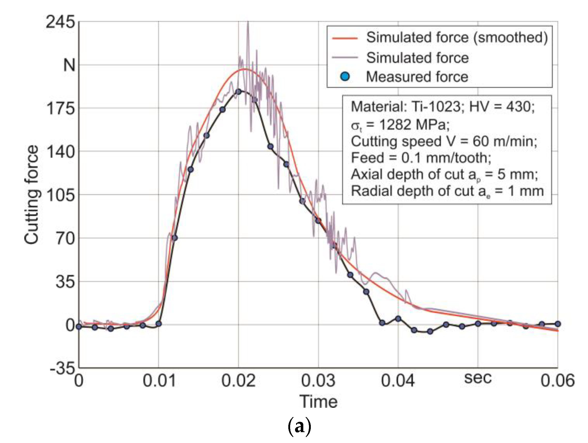
The comparison between the experimental data of cutting force as well as axial force and the corresponding simulated force values is shown in Figure 9.
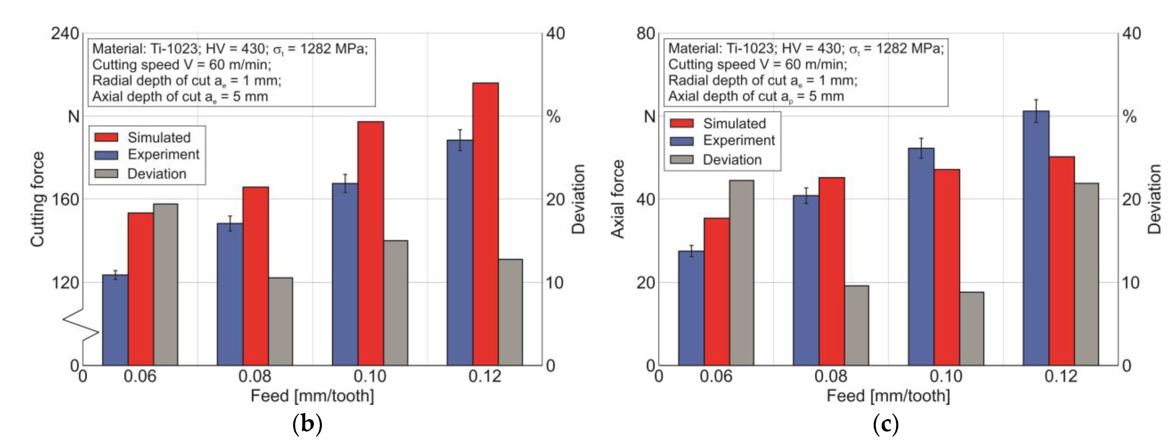
The comparison results are presented exemplarily for a cutting speed of VC = 60 m/min and a radial depth of cut of ae = 1 mm. An overlay of the simulated cutting force signal with the measured cutting force signal is shown in Figure 9a for the above cutting modes and a tool feed of f = 0.1 mm/tooth. The simulated cutting force signal of one cutter tooth agreed quite well with the measured force signal. This agreement of a single tooth from the end milling cutter suggested a satisfactory match between the simulated and measured forces acting on the tool as a whole. A comparison between the measured and simulated values of cutting force and axial force at different tool feed values is shown in Figure 9b,c. The same diagrams show the deviation values between the simulated and measured forces. The difference between simulated and measured cutting forces when the tool feed changed from 0.06 mm/tooth to 1.2 mm/tooth was around 10% to about 20%. In this case, the simulated values of cutting force exceeded the experimental data. This difference could be explained by an insufficient consideration of the thermal influence on the softening of the machined material in the cutting process, as with the analysis of the orthogonal cutting process. To reduce the effect of this disadvantage on the numerical simulation results, it was necessary to further optimize the process of determining the constitutive equation parameters with respect to the influence of real physical and mechanical processes accompanying the cutting process. The difference between the simulated and measured axial forces for the same change in tool feed ranged from around 10% to approximately 23%. For smaller tool feeds from 0.06 mm/tooth to 0.08 mm/tooth, the simulated axial force values were greater than the corresponding experimental values. For greater tool feeds from 0.1 mm/tooth to 0.12 mm/tooth, the simulated axial forces were smaller than the corresponding experimental values. At higher tool feed values, considerably more material was removed per unit of time. This led to significantly greater surface layer deformations of the machined material than at low feed values. In turn, greater deformations caused a significantly larger value of elastic recovery (spring-back) of the machined material [63,64], which, until now, has not been taken into account in numerical models of cutting processes. Thus, the effect of elastic recovery of the workpiece surface layers exceeded the effect of softening of the machined material in the real cutting process with significant deformations in the machined material. The finite element model of cutting did not take the phenomenon of spring-back into account and could not fully realize the machined material softening by means of the constitutive equation. Supposedly, the missing consideration of the spring-back effect had a greater influence on the simulation results than the insufficient consideration of the machined material softening. Therefore, great values of the simulated axial force in comparison to the experimental values due to an insufficient consideration of the machined material softening, observed at low tool feeds, transform into smaller values at large feeds.
4. Conclusions
This paper presents the results of experimental tests and numerical simulations of the orthogonal cutting and milling process of titanium alloy Ti10V2Fe3Al (Ti-1023) for a wide variation in cutting modes. Experimental examinations served as a basis for the verification of the developed planar and spatial finite element models. The two-dimensional finite-element model of orthogonal cutting was used to determine the parameters of the FE model triad: the machined material model, the contact interaction model of the tool with the chip as well as with the workpiece, and the material fracture model. The parameters of the Johnson–Cook constitutive equation used as material model parameters and the critical fracture stress value of the machined material were determined by a DOE (Design of Experiment) sensitivity analysis on a two-dimensional FE-model during the numerical simulation of orthogonal cutting processes. The specified triad parameters were also used in the three-dimensional FE model of end milling.
The results of the numerical simulation were consistently compared with the experimental data obtained. The deviations in the simulated cutting forces from their experimental values for the orthogonal cutting process were about 8% to about 12%, and the same deviations in the thrust forces were about 21% to about 25%. The simulated chip peaks and chip valleys deviated from their experimental values by between about 5% and about 13%. The superposition of simulated and measured cutting force signals for one tooth of the end milling cutter showed a good agreement and confirmed that the created FEM cutting model for milling was valid. The difference between simulated and measured cutting forces during milling for a tool feed range of 0.06 mm/tooth to 1.2 mm/tooth was about 10% to about 20%. Moreover, the difference between simulated and measured axial forces for the same range of tool feed was between about 10% and about 23%. The shortcomings of the developed methodology for the numerical modeling of titanium alloy Ti-1023 milling processes included an insufficient consideration of the thermal influence on the softening of the machined material in the cutting process and the missing consideration in the determining equation structure of the mechanism to account for the elastic recovery of the machined surface. The authors’ further studies will be partly devoted to improving the defining equation structure of the machined material state in the cutting process in order to take the influence of the above-mentioned factors into account.
A sufficient agreement between measured and simulated kinetic characteristics allows the statement to be made that the developed FEM cutting models and experimentally obtained results can be further used to optimize the cutting processes of titanium alloy Ti-1023, as well as the design and geometrical parameters of the tools. In this case, a reduction can be expected regarding the experimental test and machine operation times, as well as regarding the costs of materials, prototypes, and energy at the conventional development stages.
Author Contributions
Conceptualization, M.S.; methodology, M.S.; software, M.S.; validation, M.S.; formal analysis, M.S.; investigation, M.S.; resources, T.S. and H.-C.M.; data curation, M.S.; writing—original draft preparation, M.S.; writing—review and editing, M.S.; visualization, M.S.; project administration, H.-C.M. and T.S.; funding acquisition, H.-C.M. and T.S. All authors have read and agreed to the published version of the manuscript.
Funding
This study was funded by the German Research Foundation (DFG) in the project HE-1656/153-1 “Development of a Concept for Determining the Mechanical Properties of the Cutting Material in Machining”.
Data Availability Statement
Not applicable.
Acknowledgments
The authors would like to thank the German Research Foundation (DFG) for their support, which is highly appreciated.
Conflicts of Interest
The authors declare no conflict of interest. The funders had no role in the design of the study; in the collection, analyses, or interpretation of data; in the writing of the manuscript; or in the decision to publish the results.
References
- Mourtzis, D.; Doukas, M.; Bernidaki, D. Simulation in Manufacturing: Review and Challenges. Procedia CIRP 2014, 25, 213–229. [Google Scholar] [CrossRef] [Green Version]
- Arrazola, P.; Özel, T.; Umbrello, D.; Davies, M.; Jawahir, I. Recent advances in modelling of metal machining processes. CIRP Ann. Manuf. Technol. 2013, 62, 695–718. [Google Scholar] [CrossRef]
- Melkote, S.; Liang, S.Y.; Ozel, T.; Jawahir, I.S.; Stephenson, D.A.; Wang, B. A Review of Advances in Modeling of Conventional Machining Processes: From Merchant to the Present. ASME J. Manuf. Sci. Eng. 2022, 144, 110801. [Google Scholar] [CrossRef]
- Neugebauer, R.; Schmidt, G.; Dix, M.; Hoyer, U.K. Simulation von Span- und Gratbildung zur Qualitätserhöhung beim Bohren: Zerspanung in Grenzbereichen. In 5. Chemnitzer Produktionstechnisches Kolloquium; CPK-2008; Wissenschaftliche Scripten: Auerbach Vogtland, Germany, 2008; Volume 46, pp. 215–230. ISBN 978-3-937524-71-9. [Google Scholar]
- Isbilir, O.; Ghassemieh, E. Finite Element Analysis of Drilling of Titanium Alloy. Procedia Eng. 2011, 10, 1877–1882. [Google Scholar] [CrossRef] [Green Version]
- Tiffe, M.; Biermann, D. Modelling of Tool Engagement and FEM-Simulation of Chip Formation from Drilling Processes. Adv. Mater. Res. 2014, 1018, 183–188. [Google Scholar] [CrossRef]
- Risse, K. Einflüsse von Werkzeugdurchmesser und Schneidkantenverrundung beim Bohren mit Wendelbohrern in Stahl. Ph.D. Thesis, Rheinisch-Westfälischen Technischen Hochschule Aachen, Aachen, Germany, 2006; 137p. ISBN 978-3-8322-5252-6. [Google Scholar]
- Ma, L.; Marusich, T.D.; Usui, S.; Wadell, J.; Marusich, K.; Zamorano, L.; Elangovan, H. Validation of Finite Elemente Modeling of Drilling Processes with Solid Tooling in Metals. Adv. Mater. Res. 2011, 223, 182–190. [Google Scholar] [CrossRef]
- Özel, T.; Altan, T. Process simulation using finite element method—Prediction of cutting forces, tool stresses and temperatures in high-speed flat end milling. Int. J. Mach. Tools Manuf. 2000, 40, 713–738. [Google Scholar] [CrossRef]
- Mattes, A. Zerspansimulationslösungen für die Werkzeugkonstruktion und Prozessauslegung beim Fräsen. Ph.D. Dissertation, Fraunhofer-Institut für Produktionsanlagen und Konstruktionstechnik, Berlin, Germany, 2008; 169p. ISBN 978-3-8167-7847-9. [Google Scholar]
- Khosravi, J.; Azarhoushang, B.; Barmouz, M.; Bösinger, R.; Zahedi, A. High-speed milling of Ti6Al4V under a supercritical CO2 + MQL hybrid cooling system. J. Manuf. Processes 2022, 82, 1–14. [Google Scholar] [CrossRef]
- Thepsonthi, T.; Özel, T. 3-D finite element process simulation of micro-end milling Ti-6Al-4V titanium alloy: Experimental validations on chip flow and tool wear. J. Mater. Process. Technol. 2015, 221, 128–145. [Google Scholar] [CrossRef]
- Söhner, J. Beitrag zur Simulation zerspanungstechnologischer Vorgänge mit Hilfe der Finite-Elemente-Methode. Ph.D. Dissertation, Universität Karlsruhe, Karlsruhe, Germany, 2003; 148p. [Google Scholar] [CrossRef]
- Wu, H.B.; Zhang, S.J. 3D FEM simulation of milling process for titanium alloy Ti6Al4V. Int. J. Adv. Manuf. Technol. 2014, 71, 1319–1326. [Google Scholar] [CrossRef]
- Recht, R.F. Catastrophic Thermoplastic Shear. ASME J. Appl. Mech. 1964, 31, 189–193. [Google Scholar] [CrossRef]
- Heisel, U.; Krivoruchko, D.V.; Zaloha, W.A.; Storchak, M.; Stehle, T. Breakage models for the modeling of cutting processes. ZWF Z. Fuer Wirtsch. Fabr. 2009, 104, 330–339. [Google Scholar] [CrossRef]
- Zorev, N.N. Metal Cutting Mechanics; Pergamon Press: Frankfurt am Main, Germany, 1966; 526p, ISBN 978-0080107233. [Google Scholar]
- Heisel, U.; Krivoruchko, D.V.; Zaloha, W.A.; Storchak, M.; Stehle, T. Thermomechanical exchange effects in machining. ZWF Z. Fuer Wirtsch. Fabr. 2009, 104, 263–272. [Google Scholar] [CrossRef]
- Zhanga, Y.; Outeiro, J.C.; Mabroukic, T. On the selection of Johnson-Cook constitutive model parameters for Ti-6Al-4V using three types of numerical models of orthogonal cutting. Procedia CIRP 2015, 31, 112–117. [Google Scholar] [CrossRef]
- Sima, M.; Özel, T. Modified material constitutive models for serrated chip formation simulations and experimental validation in machining of titanium alloy Ti-6Al-4V. Int. J. Mach. Tools Manuf. 2010, 50, 943–960. [Google Scholar] [CrossRef]
- Cheng, W.; Outeiro, J.C. Modelling orthogonal cutting of Ti-6Al-4 V titanium alloy using a constitutive model considering the state of stress. Int. J. Adv. Manuf. Technol. 2022, 119, 4329–4347. [Google Scholar] [CrossRef]
- Calamaz, M.; Coupard, D.; Girot, F. A new material model for 2D numerical simulation of serrated chip formation when machining titanium alloy Ti–6Al–4V. Int. J. Mach. Tools Manuf. 2008, 48, 275–288. [Google Scholar] [CrossRef] [Green Version]
- Karpat, Y. Temperature dependent flow softening of titanium alloy Ti6Al4V: An investigation using finite element simulation of machining. J. Mater. Process. Technol. 2011, 211, 737–749. [Google Scholar] [CrossRef] [Green Version]
- Sui, X.; Zhang, S.; Guan, Y.; Chen, B. 3-D Finite Element Simulation Analysis of Milling Titanium Alloy Using Different Cutting Edge Radius. In Proceedings of the 2015 Sixth International Conference on Intelligent Systems Design and Engineering Applications (ISDEA), Guiyang, China, 18–19 August 2015. [Google Scholar] [CrossRef]
- Chen, X.; Khatri, A.; Ma, J.; Jahan, M.P. Numerical Investigation of the Slot Up Milling of Ti-6Al-4V. In Proceedings of the ASME 2018 13th International Manufacturing Science and Engineering Conference, College Station, TX, USA, 18–22 June 2018. [Google Scholar] [CrossRef]
- Daniyan, I.; Fameso, F.; Ale, F.; Bello, K.; Tlhabadira, I. Modelling, simulation and experimental validation of the milling operation of titanium alloy (Ti6Al4V). Int. J. Adv. Manuf. Technol. 2020, 109, 1853–1866. [Google Scholar] [CrossRef]
- Saleem, W.; Salah, B.; Velay, X.; Ahmad, R.; Khan, R.; Pruncu, C.I. Numerical Modeling and Analysis of Ti6Al4V Alloy Chip for Biomedical Applications. Materials 2020, 13, 5236. [Google Scholar] [CrossRef]
- Chen, G.; Ren, C.; Yang, X.; Jin, X.; Guo, T. Finite element simulation of high-speed machining of titanium alloy (Ti–6Al–4V) based on ductile failure model. Int. J. Adv. Manuf. Technol. 2011, 56, 1027–1038. [Google Scholar] [CrossRef]
- Gamboa, C.B.; Andersson, T.; Svensson, D.; Vilches, F.J.T.; Martín-Béjar, S.; Hurtado, L.S. Modeling of the fracture energy on the finite element simulation in Ti6Al4V alloy machining. Sci. Rep. 2021, 11, 18490. [Google Scholar] [CrossRef] [PubMed]
- Wang, Z.; Ze, X.; Yousuf, Y.A.; Jiang, Z.; Fu, X.; Pan, Y. Three-dimensional finite element simulation of high speed milling of titanium alloy Ti6Al4V. J. Phys. 2021, 1948, 012130. [Google Scholar] [CrossRef]
- Mugilan, T.; Alwarsamy, T. Prediction of cutting forces during end milling using 3D FEM based simulation analysis. Int. J. Veh. Struct. Syst. 2020, 12, 26–30. [Google Scholar] [CrossRef]
- Sun, P.; Zhang, Z.; Tian, Y.; Wang, Z.; Su, J.; Zhang, Y.; Wang, Z.; Hui, J.; Zhang, B.; He, L.; et al. Modeling and simulation of dynamic milling force for cast titanium alloy using flat end mills. In Proceedings of the International Conference on Mechanical Design and Simulation (MDS 2022), Wuhan, China, 18–20 March 2022; p. 1226137. [Google Scholar] [CrossRef]
- Pan, Z.; Liang, S.Y.; Garmestani, H. Finite element simulation of residual stress in machining of Ti-6Al-4V with a microstructural consideration. Proc. Inst. Mech. Eng. Part B J. Eng. Manuf. 2019, 233, 1103–1111. [Google Scholar] [CrossRef]
- Arisoy, Y.; Guo, C.; Kaftanoglu, B.; Özel, T. Investigations on microstructural changes in machining of Inconel 100 alloy using face turning experiments and 3D finite element simulations. Int. J. Mech. Sci. 2016, 107, 80–92. [Google Scholar] [CrossRef]
- Boyer, R.R.; Briggs, R.D. The Use of ß-Titanium Alloys in the Aerospace Industry. J. Mater. Eng. Perform. 2005, 14, 681–685. [Google Scholar] [CrossRef]
- Changfeng, Y.; Daoxia, W.; Liang, T.; Junxue, R.; Kaining, S.; Zhenchao, Y. Effects of cutting parameters on surface residual stress and its mechanism in high-speed milling of TB6. Proc. Inst. Mech. Eng. Part B J. Eng. Manuf. 2013, 227, 483–493. [Google Scholar] [CrossRef]
- Yao, C.; Wu, D.-X.; Jin, Q.-C.; Huang, X.-C.; Ren, J.-X.; Zhang, D.-H. Influence of high-speed milling parameter on 3D surface topography and fatigue behavior of TB6 titanium alloy. Trans. Nonferrous Met. Soc. China 2013, 23, 650–660. [Google Scholar] [CrossRef]
- Yang, H.; Chen, Z.; Like, J. Experimental study on hardness of titanium alloy Ti-1023 by milling. Adv. Mater. Res. 2013, 690, 2446–2449. [Google Scholar] [CrossRef]
- Yang, H.; Chen, Z.; Chen, M. Experimental Study on the Impact of Cutting Speed on Surface Integrity of Ti-10V-2Fe-3Al. Adv. Mater. Res. 2014, 852, 476–480. [Google Scholar] [CrossRef]
- Yang, H.; Chen, Z.; Zhou, Z. Influence of cutting speed and tool wear on the surface integrity of the titanium alloy Ti-1023 during milling. Int. J. Adv. Manuf. Technol. 2015, 78, 1113–1126. [Google Scholar] [CrossRef] [Green Version]
- Liu, D.; Wang, F.; Wang, J.M.; Xue, Y.; Xue, J. Orthogonal Experimental Study on Tool Life in Milling TB6 Titanium Alloy. IOP Conf. Ser. Mater. Sci. Eng. 2017, 265, 012018. [Google Scholar] [CrossRef]
- Rashid, R.A.R.; Sun, S.; Palanisamy, S.; Wang, G.; Dargusch, M.S. A study on laser assisted machining of Ti10V2Fe3Al alloy with varying laser power. Int. J. Adv. Manuf. Technol. 2014, 74, 219–224. [Google Scholar] [CrossRef]
- Wagner, V.; Duc, E. Study of Ti-1023 milling with toroidal tool. Int. J. Adv. Manuf. Technol. 2014, 75, 1473–1491. [Google Scholar] [CrossRef] [Green Version]
- Storchak, M.; Jiang, L.; Xu, Y.; Li, X. Finite element modeling for the cutting process of the titanium alloy Ti10V2Fe3Al. Prod. Eng. Res. Dev. 2016, 10, 509–517. [Google Scholar] [CrossRef]
- Jaiswal, A.P.; Khanna, N.; Bajpai, V. Orthogonal machining of Heat Treated Ti-10-2-3: FE and Experimental. Mater. Manuf. Processes 2020, 35, 1822–1831. [Google Scholar] [CrossRef]
- Lei, Z.; Pei, L. Cutting mechanism of straight-tooth milling process of titanium alloy TC21 based on simulation and experiment. PLoS ONE 2021, 16, e0258403. [Google Scholar] [CrossRef]
- Boyer, R.R. Design Properties of a High-Strength Titanium Alloy, Ti-10V-2Fe-3Al. J. Met. 1980, 32, 61–65. [Google Scholar] [CrossRef]
- Storchak, M.; Stehle, T.; Möhring, H.-C. Determination of thermal material properties for the numerical simulation of cutting processes. Int. J. Adv. Manuf. Technol. 2022, 118, 1941–1956. [Google Scholar] [CrossRef]
- Kushner, V.; Storchak, M. Determining mechanical characteristics of material resistance to deformation in machining. Prod. Eng. Res. Dev. 2014, 8, 679–688. [Google Scholar] [CrossRef]
- Tsekhanov, J.; Storchak, M. Development of analytical model for orthogonal cutting. Production Engineering. Res. Dev. 2015, 9, 247–255. [Google Scholar] [CrossRef]
- Johnson, G.R.; Cook, W.H. A constitutive model and data for metals subjected to large strains, high strain and high temperatures. In Proceedings of the 7th International Symposium on Ballistics, The Hague, The Netherlands, 19–21 April 1983; pp. 541–547. [Google Scholar]
- Cockroft, M.G.; Latham, D.J. Ductility and workability of metals. J. Inst. Met. 1968, 96, 33–39. [Google Scholar] [CrossRef]
- Filatov, Y.D.; Filatov, A.Y.; Syrota, O.O.; Yashchuk, V.P.; Monteil, G.; Heisel, U.; Storchak, M. The influence of tool wear particles scattering in the contact zone on the workpiece surface microprofile formation in polishing quartz. J. Superhard Mater. 2010, 32, 415–422. [Google Scholar] [CrossRef]
- Filatov, Y.D.; Sidorko, V.I.; Filatov, O.Y.; Yaschuk, V.P.; Heisel, U.; Storchak, M. Surface quality control in diamond abrasive finishing. Proc. SPIE 2009, 7389, 73892O. [Google Scholar] [CrossRef]
- Kushner, V.; Storchak, M. Modelling the Material Resistance to Cutting. Int. J. Mech. Sci. 2017, 126, 44–54. [Google Scholar] [CrossRef]
- Fluhrer, J. Deform—User Manual Deform V12.0; SFTC: Columbus, OH, USA, 2019. [Google Scholar]
- Heisel, U.; Krivoruchko, D.V.; Zaloha, W.A.; Storchak, M.; Stehle, T. Thermomechanical material models in the modeling of cutting processes. ZWF Z. Fuer Wirtsch. Fabr. 2009, 104, 482–491. [Google Scholar] [CrossRef]
- Storchak, M.; Möhring, H.-C.; Stehle, T. Improving the friction model for the simulation of cutting processes. Tribol. Int. 2022, 167, 107376. [Google Scholar] [CrossRef]
- Storchak, M.; Stehle, T.; Möhring, H.-C. Determination of the Shear Angle in the Orthogonal Cutting Process. J. Manuf. Mater. Process. 2022, 6, 132. [Google Scholar] [CrossRef]
- Storchak, M.; Drewle, K.; Menze, C.; Stehle, T.; Möhring, H.-C. Determination of the Tool–Chip Contact Length for the Cutting Processes. Materials 2022, 15, 3264. [Google Scholar] [CrossRef]
- Sun, S.; Brandt, M.; Dargusch, M.S. Characteristics of cutting forces and chip formation in machining of titanium alloys. Int. J. Mach. Tools Manuf. 2009, 49, 561–568. [Google Scholar] [CrossRef]
- Kushner, V.; Storchak, M. Determination of Material Resistance Characteristics in Cutting. Procedia CIRP 2017, 58, 293–298. [Google Scholar] [CrossRef]
- Schaal, N.; Kuster, F.; Wegener, K. Springback in metal cutting with high cutting speeds. Procedia CIRP 2015, 31, 24–28. [Google Scholar] [CrossRef] [Green Version]
- Storchak, M.; Zakiev, I.; Träris, L. Mechanical properties of subsurface layers in the machining of the titanium alloy Ti10V2Fe3Al. J. Mech. Sci. Technol. 2018, 32, 315–322. [Google Scholar] [CrossRef]
Figure 1.
Flowchart of the information flows logical relationship in the developed methodology.
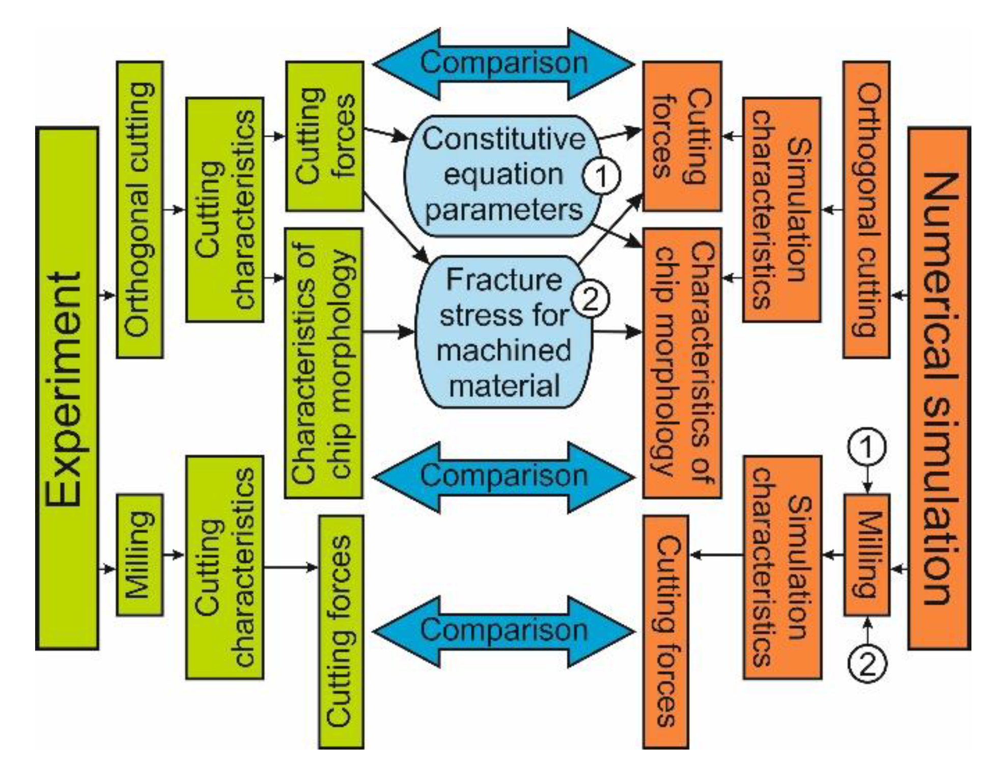
Figure 2.
Test setup for analyzing the milling process: (a) test setup and (b) milling cutter.
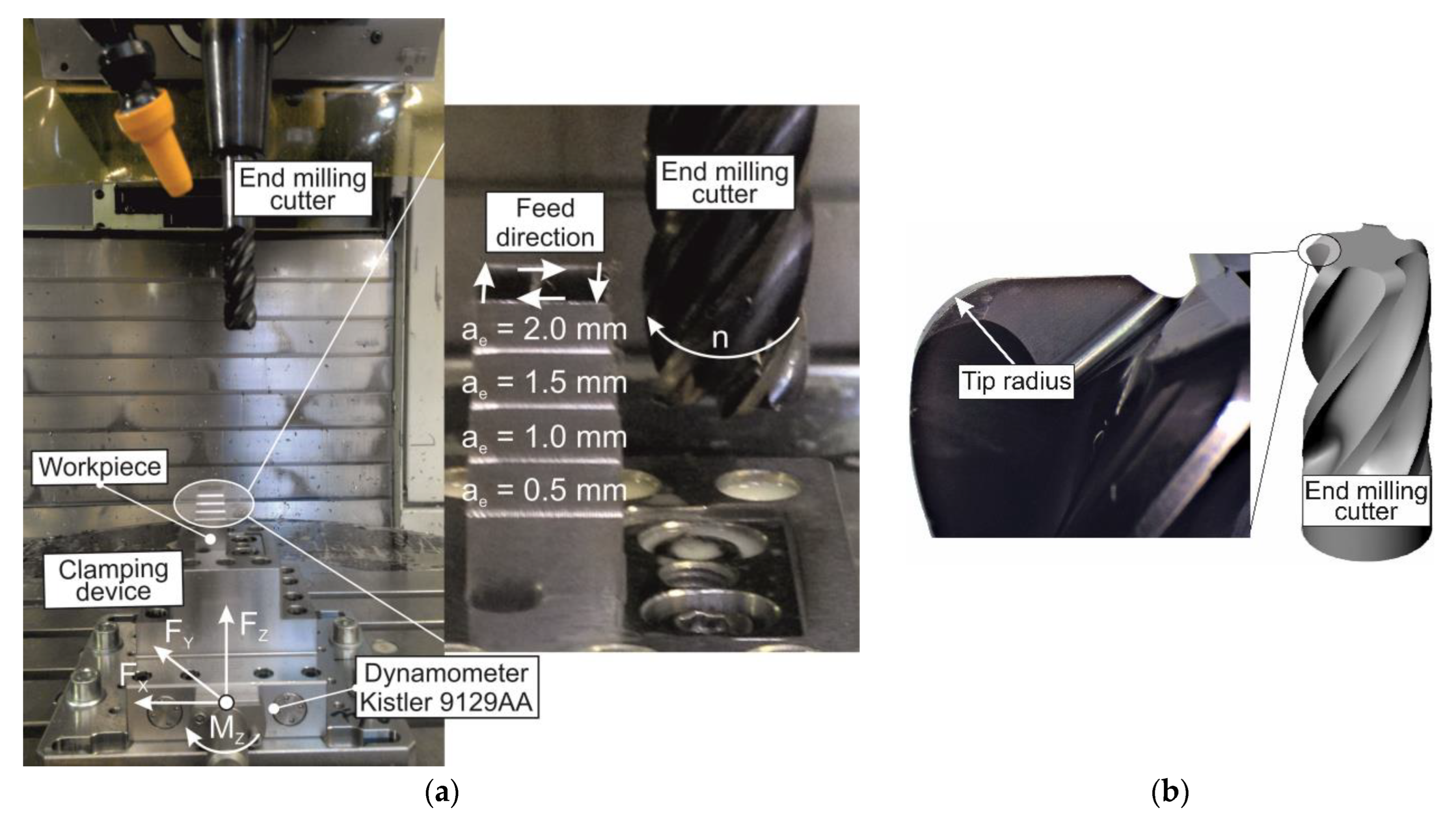
Figure 3.
Configuration of computational mesh formations “tool–workpiece” with specified boundary conditions for orthogonal cutting process.
Figure 3.
Configuration of computational mesh formations “tool–workpiece” with specified boundary conditions for orthogonal cutting process.
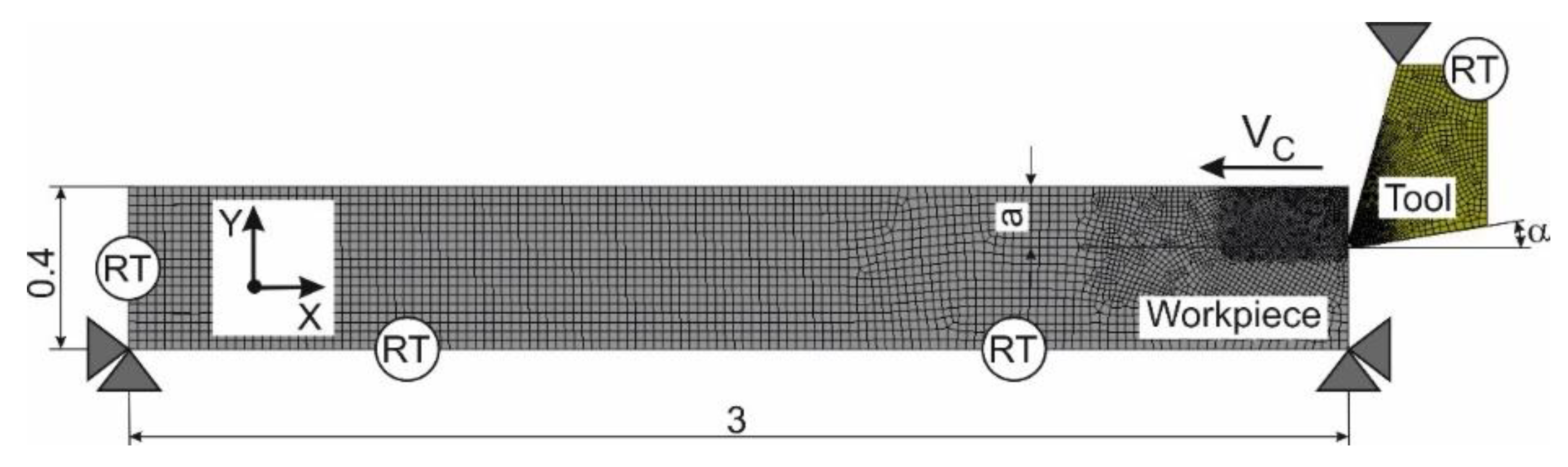
Figure 4.
Initial geometry, mesh, and boundary conditions of milling model.
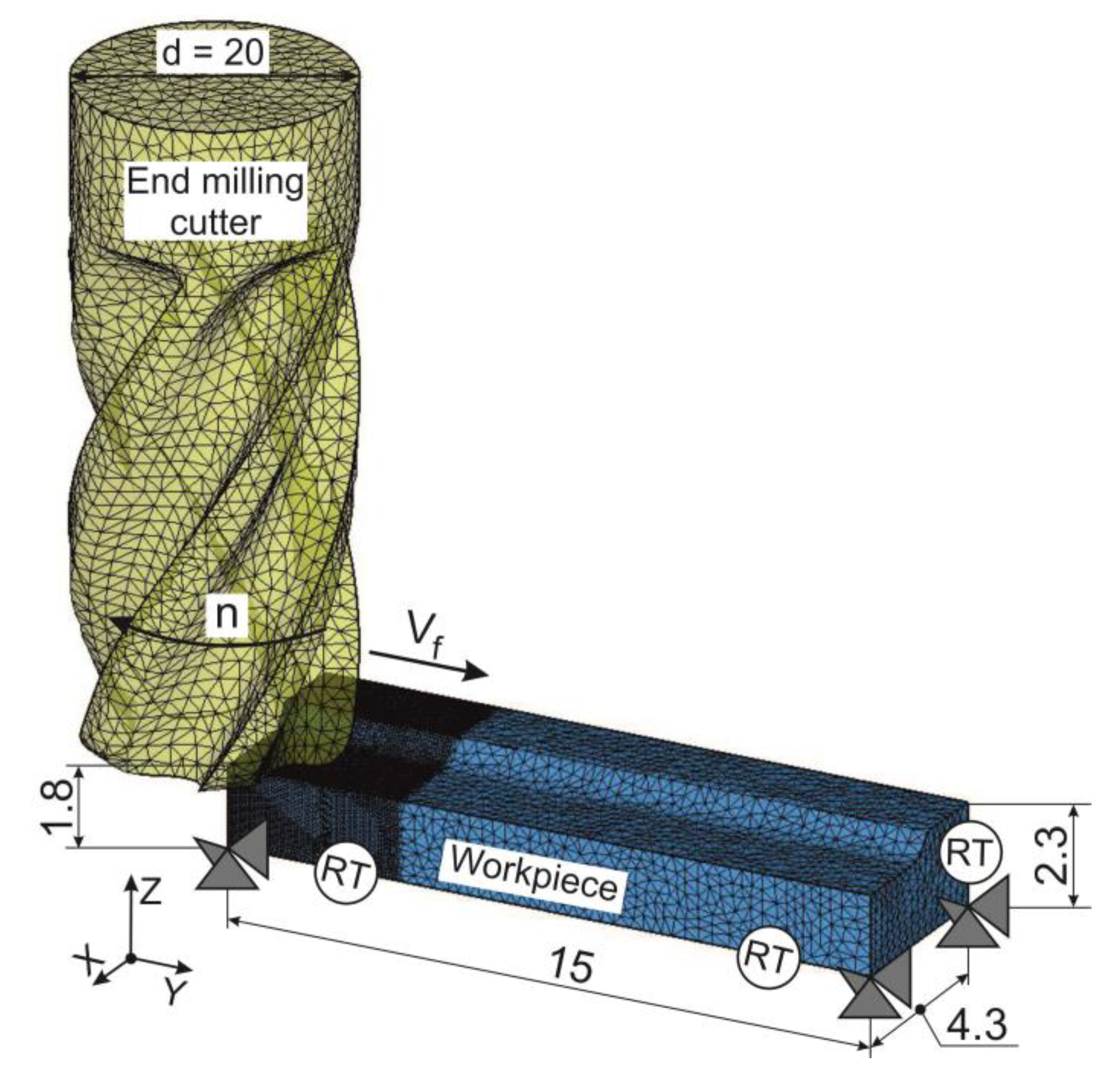
Figure 5.
Changing kinetic characteristics during the orthogonal cutting process depending on cutting speed and tool rake angle: (a) signal of cutting force Fx, (b) cutting force Fx depending on cutting speed, (c) thrust force Fz depending on cutting speed, (d) cutting force Fx depending on tool rake angle, and (e) thrust force Fz depending on tool rake angle.
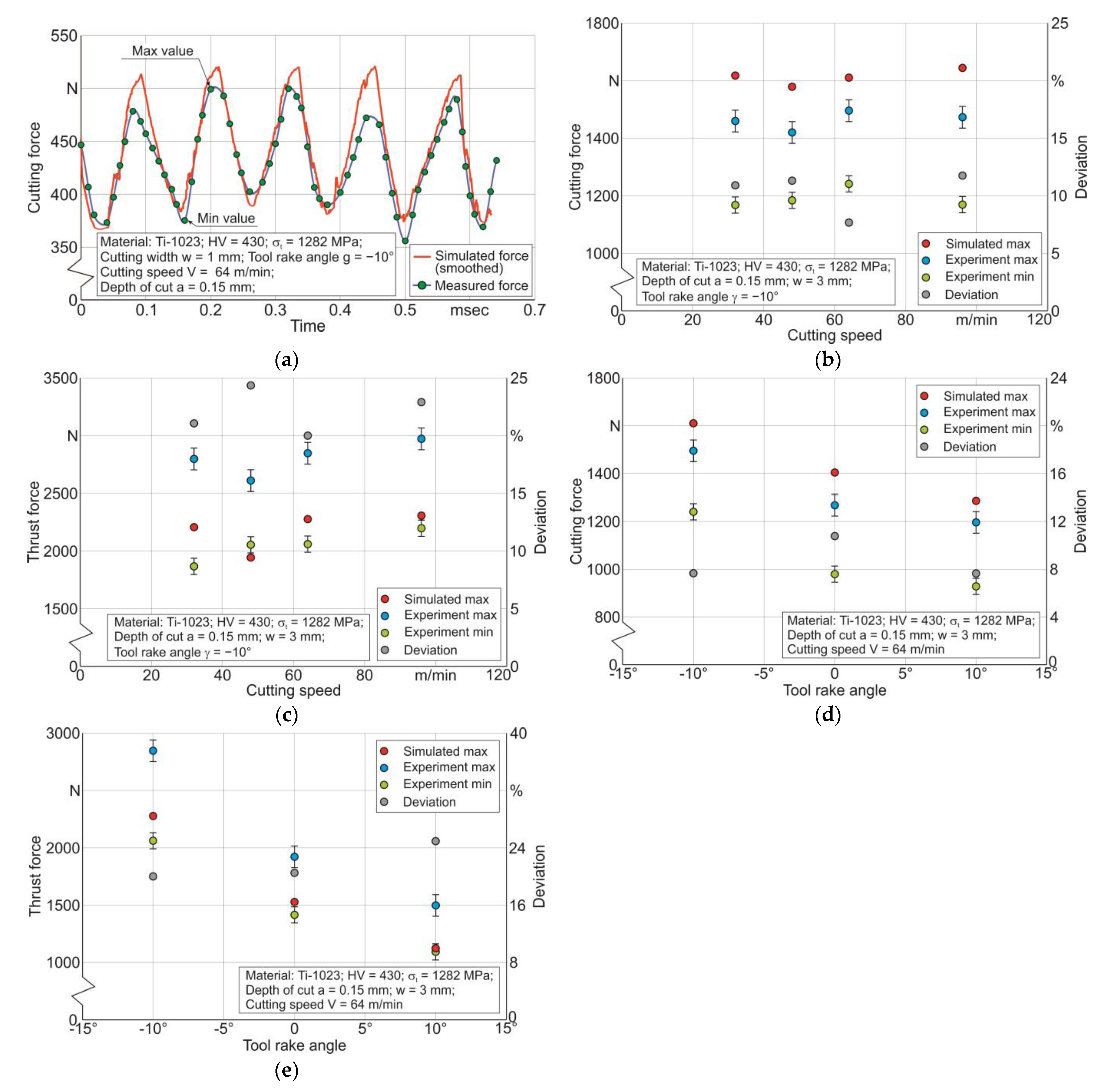
Figure 6.
Changing chip thickness depending on tool rake angle: (a) experimental chip morphology, (b) distribution of effective strain in the simulated chip, (c) chip peaks axE and axS depending on tool rake angle, and (d) chip valleys anE and anS depending on tool rake angle.
Figure 6.
Changing chip thickness depending on tool rake angle: (a) experimental chip morphology, (b) distribution of effective strain in the simulated chip, (c) chip peaks axE and axS depending on tool rake angle, and (d) chip valleys anE and anS depending on tool rake angle.
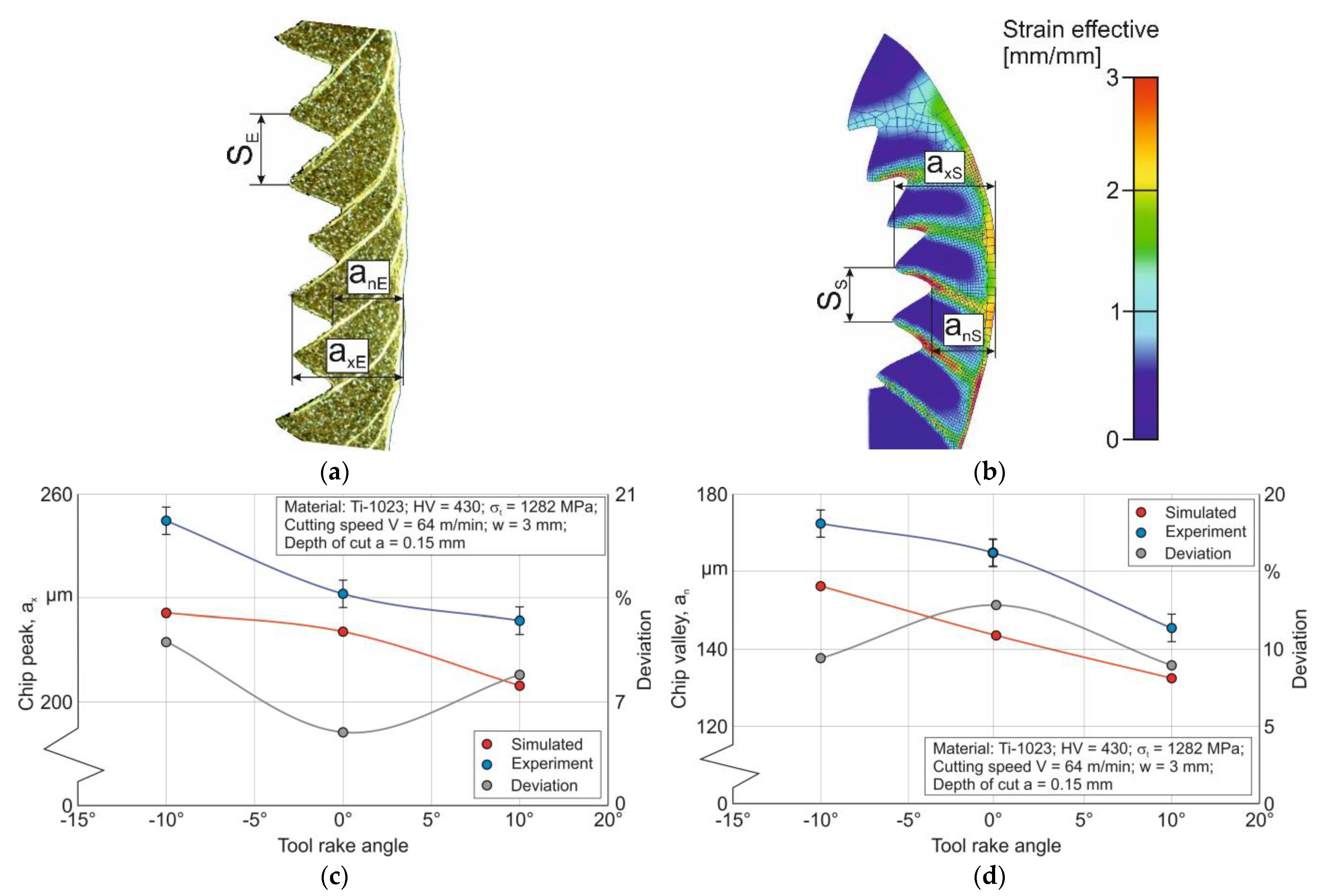
Figure 7.
Effects of radial depth of cut and tool feed on the cutting force and axial force for different cutting speeds: (a) effect of radial depth of cut on the cutting force, (b) effect of radial depth of cut on the axial force, (c) effect of feed on the cutting force, and (d) effect of feed on the axial force.
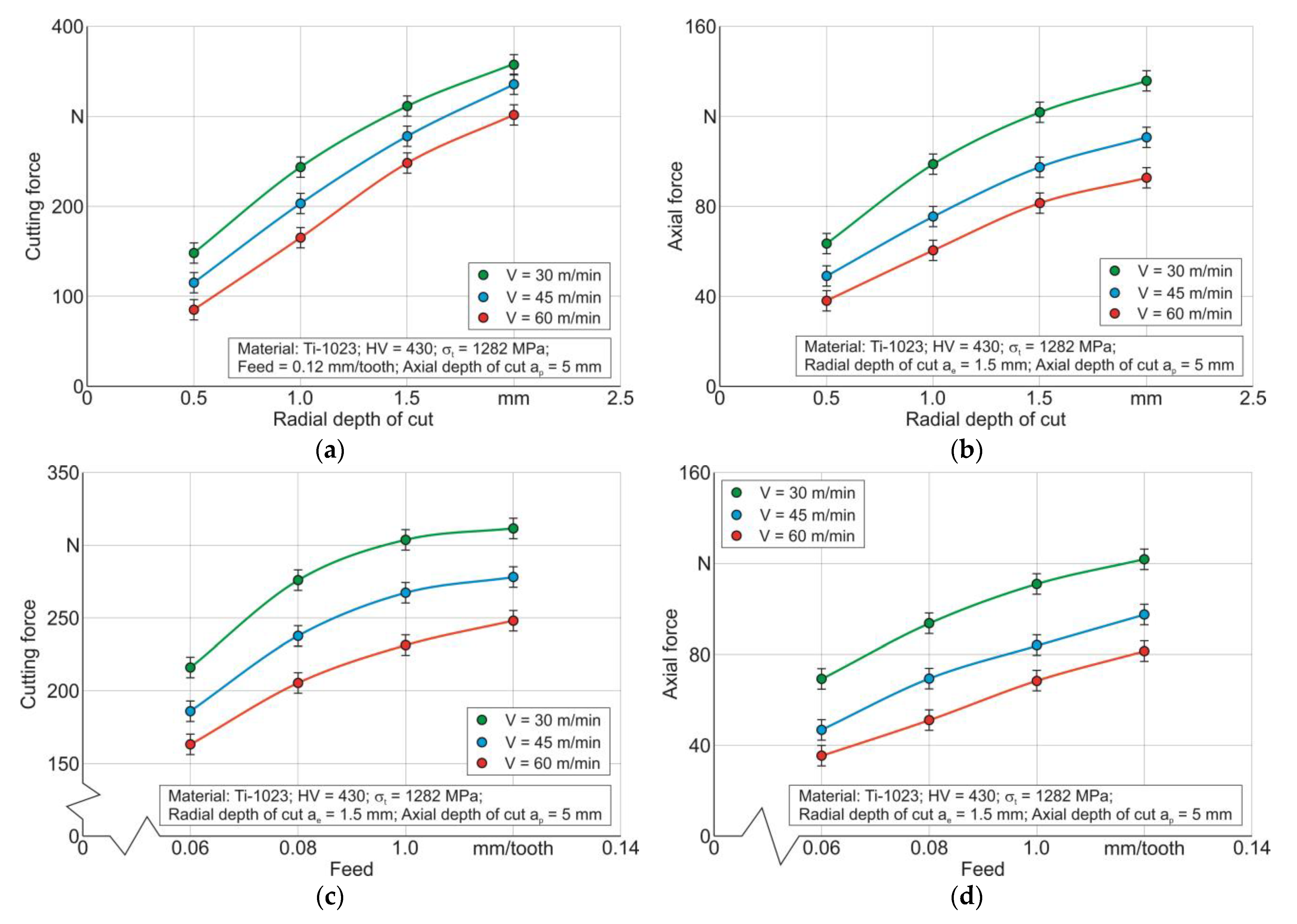
Figure 8.
Simulation of milling characteristics at different machining phases: (a) workpiece and chip strain in the initial simulation steps, (b) workpiece and chip temperature in the initial simulation steps, (c) workpiece and chip strain in the next simulation steps, (d) workpiece and chip temperature in the next simulation steps, (e) workpiece and chip stress in the initial simulation steps, and (f) workpiece and chip stress in the next simulation steps.
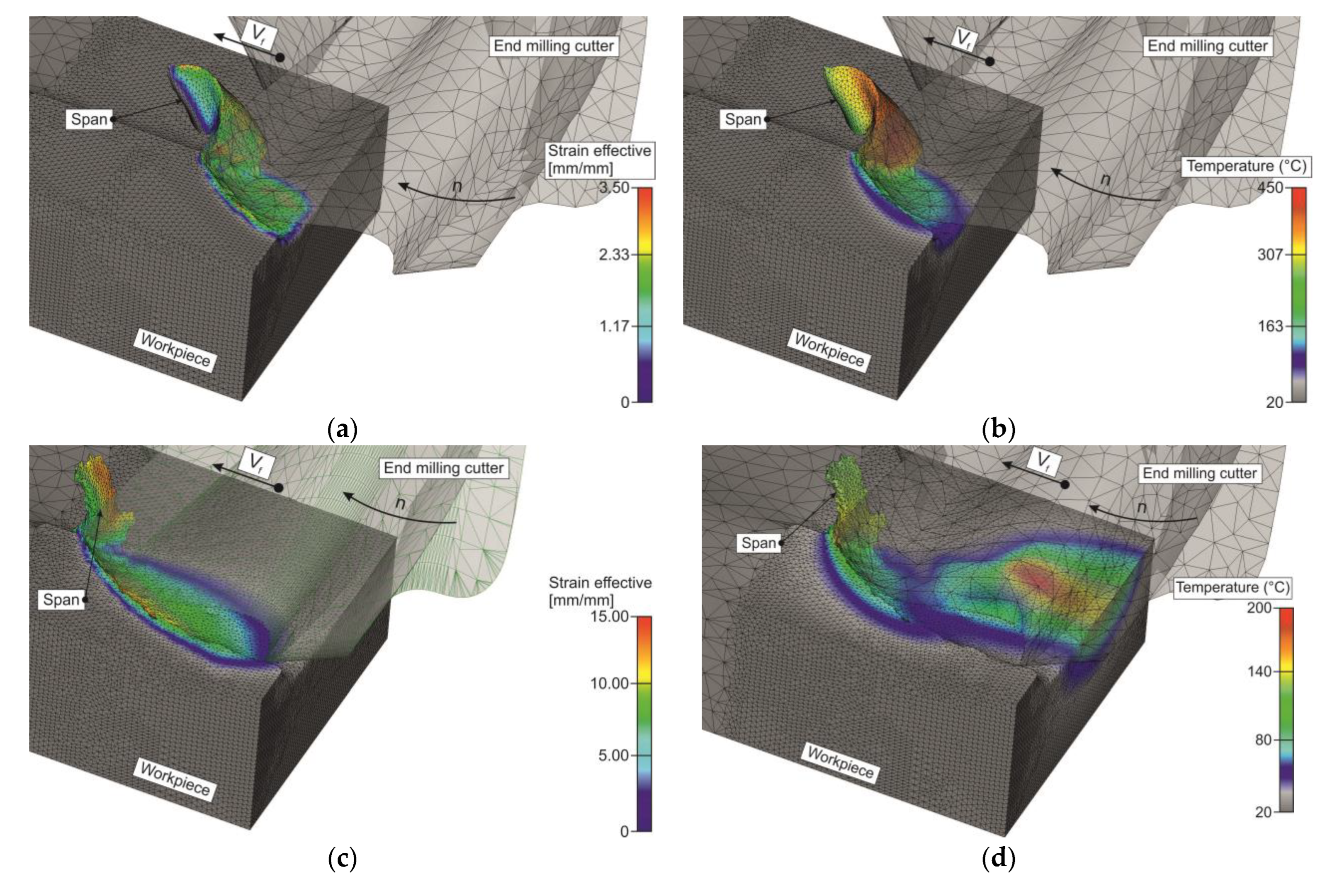
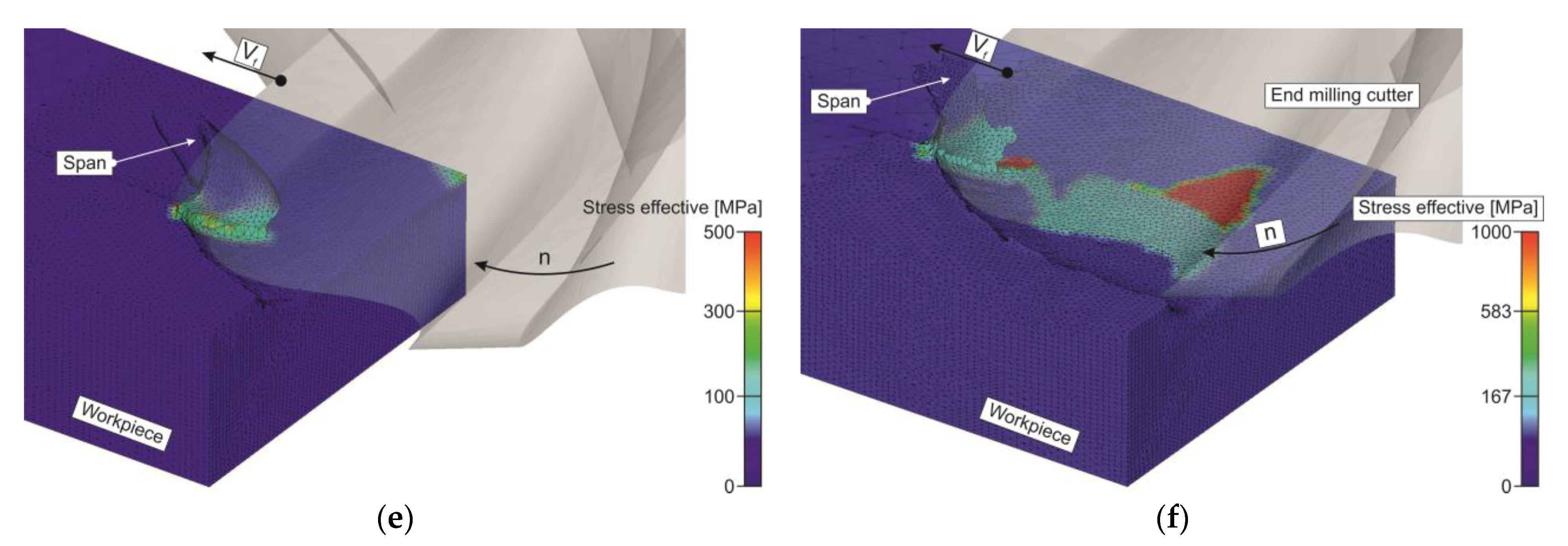
Figure 9.
Comparison between experimental and simulated values of cutting forces for different tool feeds: (a) experimental and simulated cutting force signal for one tooth of an end milling cutter, (b) comparison between experimental and simulated cutting forces, and (c) comparison between experimental and simulated axial forces.

| Material | Strength (MPa) | Elastic Modulus (GPa) | Elongation (%) | Hardness HV | Poisson’s Ratio | Specific Heat (J/kg·K) | Thermal Expansion (µm/m·°C) | Thermal Conductivity (W/m·K) | |
|---|---|---|---|---|---|---|---|---|---|
| Tensile | Yield | ||||||||
| Ti-1023 | 1282 | 1220 | 110 | 4 ~ 10 | ~430 | 0.35 | 527 | 9.7 | 7 |
Table 2.
Johnson–Cook constitutive equation parameters.
| Constitutive Parameters | ||||
|---|---|---|---|---|
| A (MPa) | B (MPa) | n | C | m |
| 985.7 | 634.7 | 0.2351 | 0.02812 | 0.87 |
Disclaimer/Publisher’s Note: The statements, opinions and data contained in all publications are solely those of the individual author(s) and contributor(s) and not of MDPI and/or the editor(s). MDPI and/or the editor(s) disclaim responsibility for any injury to people or property resulting from any ideas, methods, instructions or products referred to in the content. |
© 2022 by the authors. Licensee MDPI, Basel, Switzerland. This article is an open access article distributed under the terms and conditions of the Creative Commons Attribution (CC BY) license (https://creativecommons.org/licenses/by/4.0/).
Share and Cite
MDPI and ACS Style
Storchak, M.; Stehle, T.; Möhring, H.-C. Numerical Modeling of Titanium Alloy Ti10V2Fe3Al Milling Process. J. Manuf. Mater. Process. 2023, 7, 1. https://doi.org/10.3390/jmmp7010001
AMA Style
Storchak M, Stehle T, Möhring H-C. Numerical Modeling of Titanium Alloy Ti10V2Fe3Al Milling Process. Journal of Manufacturing and Materials Processing. 2023; 7(1):1. https://doi.org/10.3390/jmmp7010001
Chicago/Turabian StyleStorchak, Michael, Thomas Stehle, and Hans-Christian Möhring. 2023. "Numerical Modeling of Titanium Alloy Ti10V2Fe3Al Milling Process" Journal of Manufacturing and Materials Processing 7, no. 1: 1. https://doi.org/10.3390/jmmp7010001