
Thermal Post-Processing of 3D Printed Polypropylene Parts for Vacuum Systems


Abstract
:1. Introduction
2. Materials and Methods
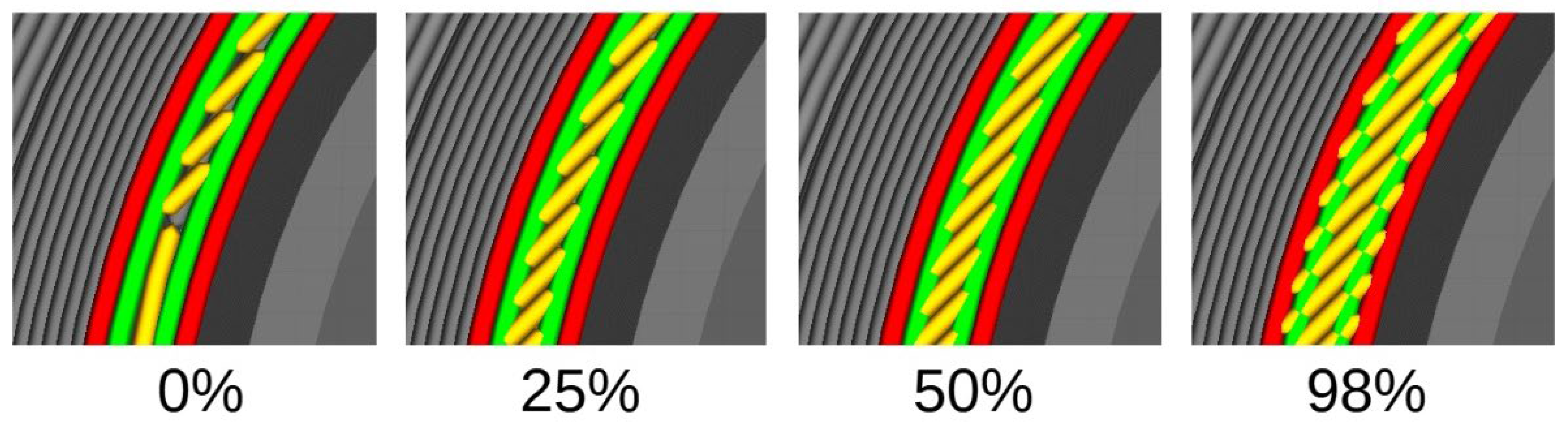
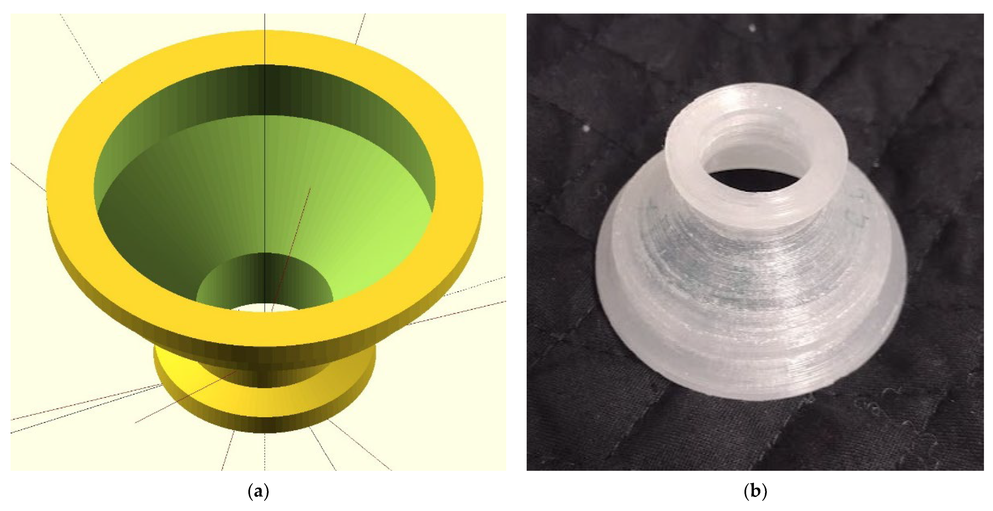
2.1. Sample Design
2.2. Fabrication
2.3. Heat Treatment
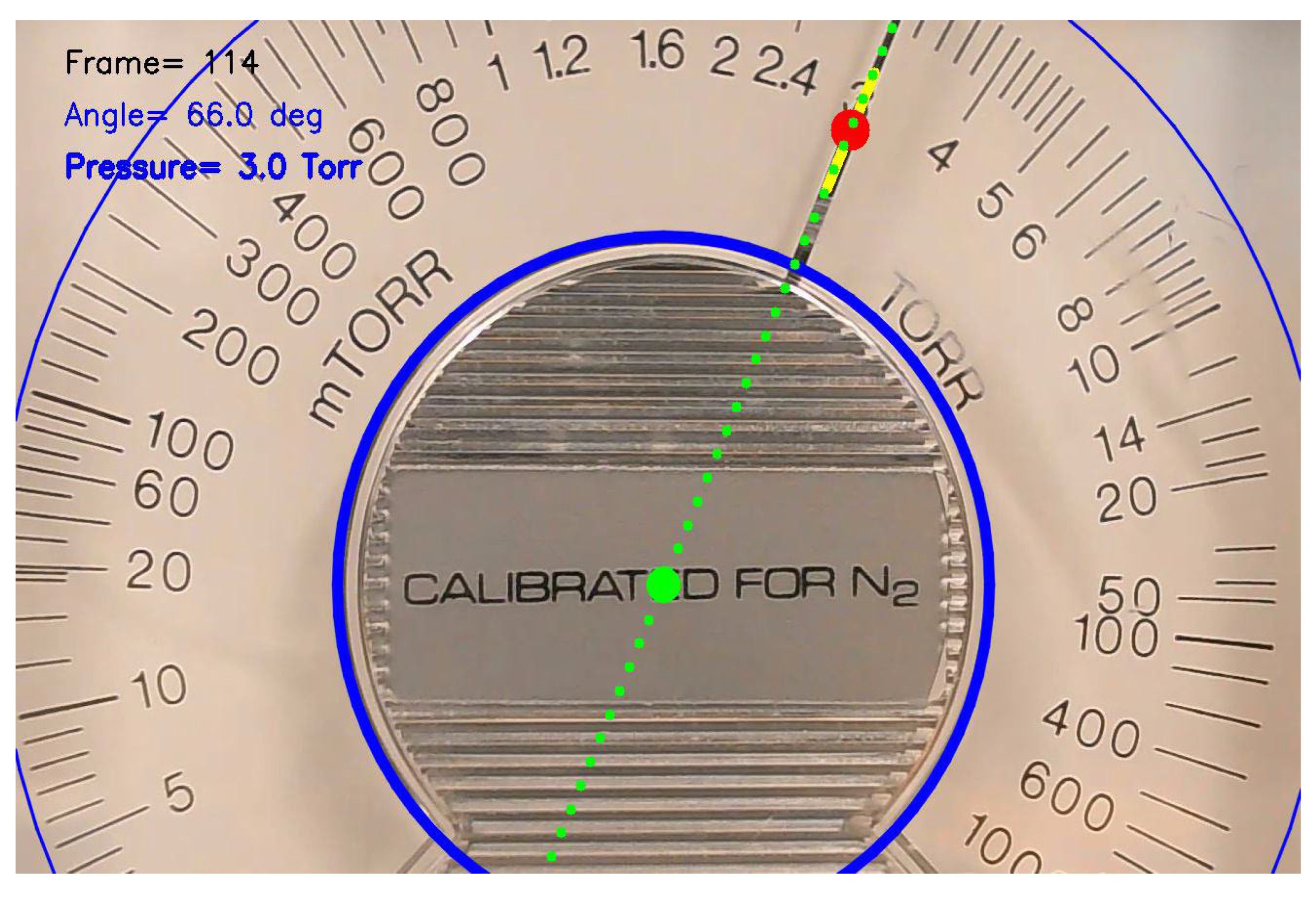
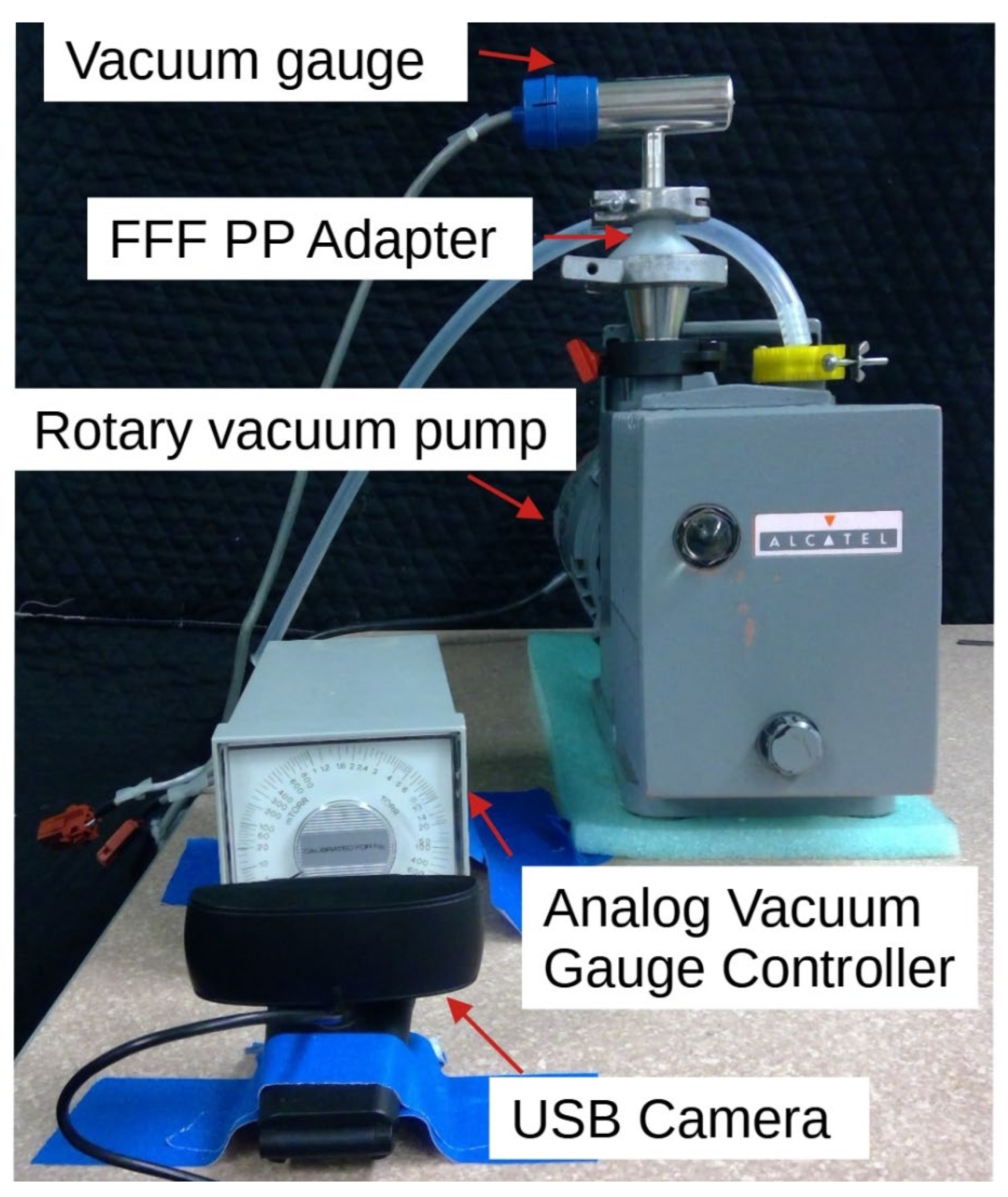
2.4. Vacuum Testing
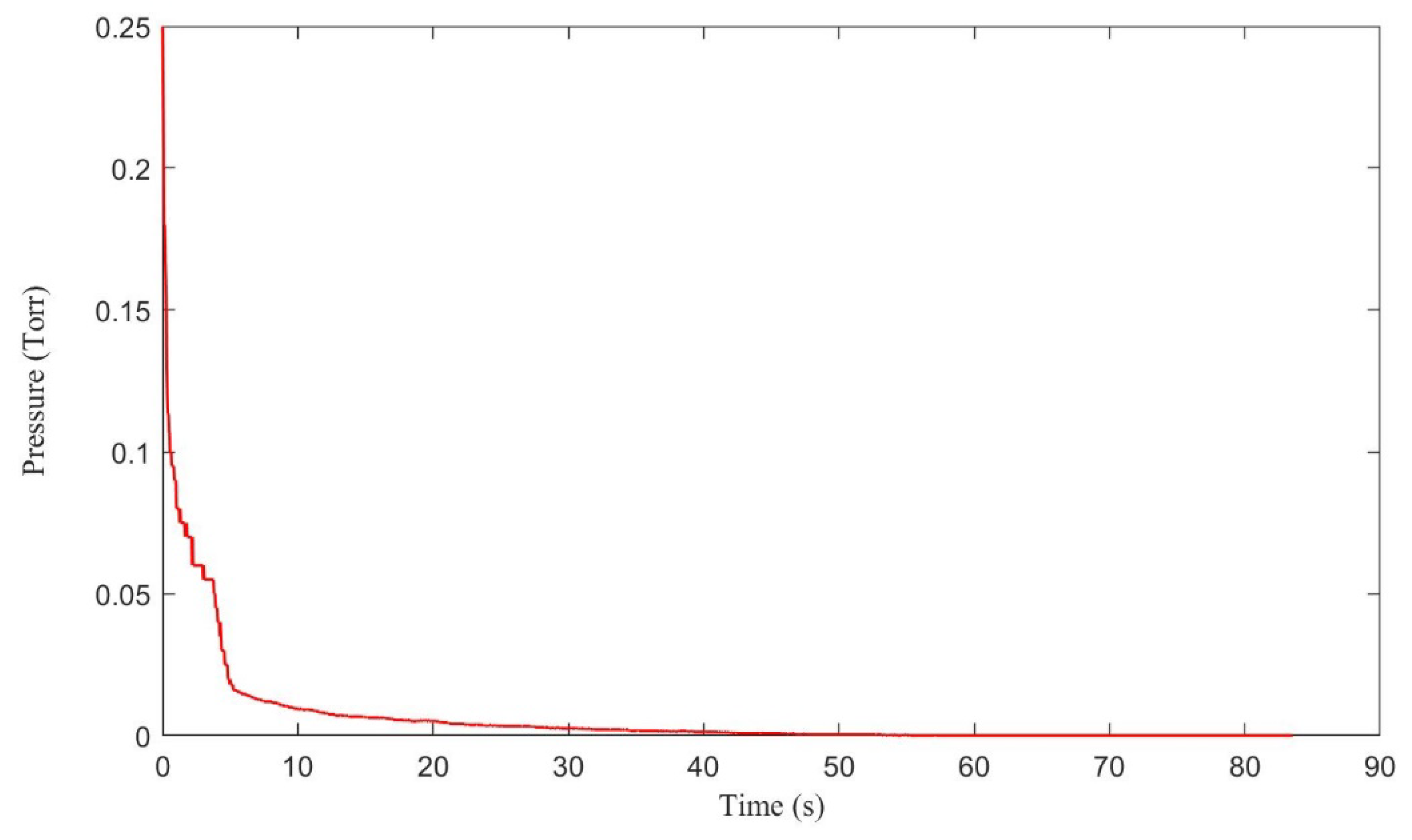
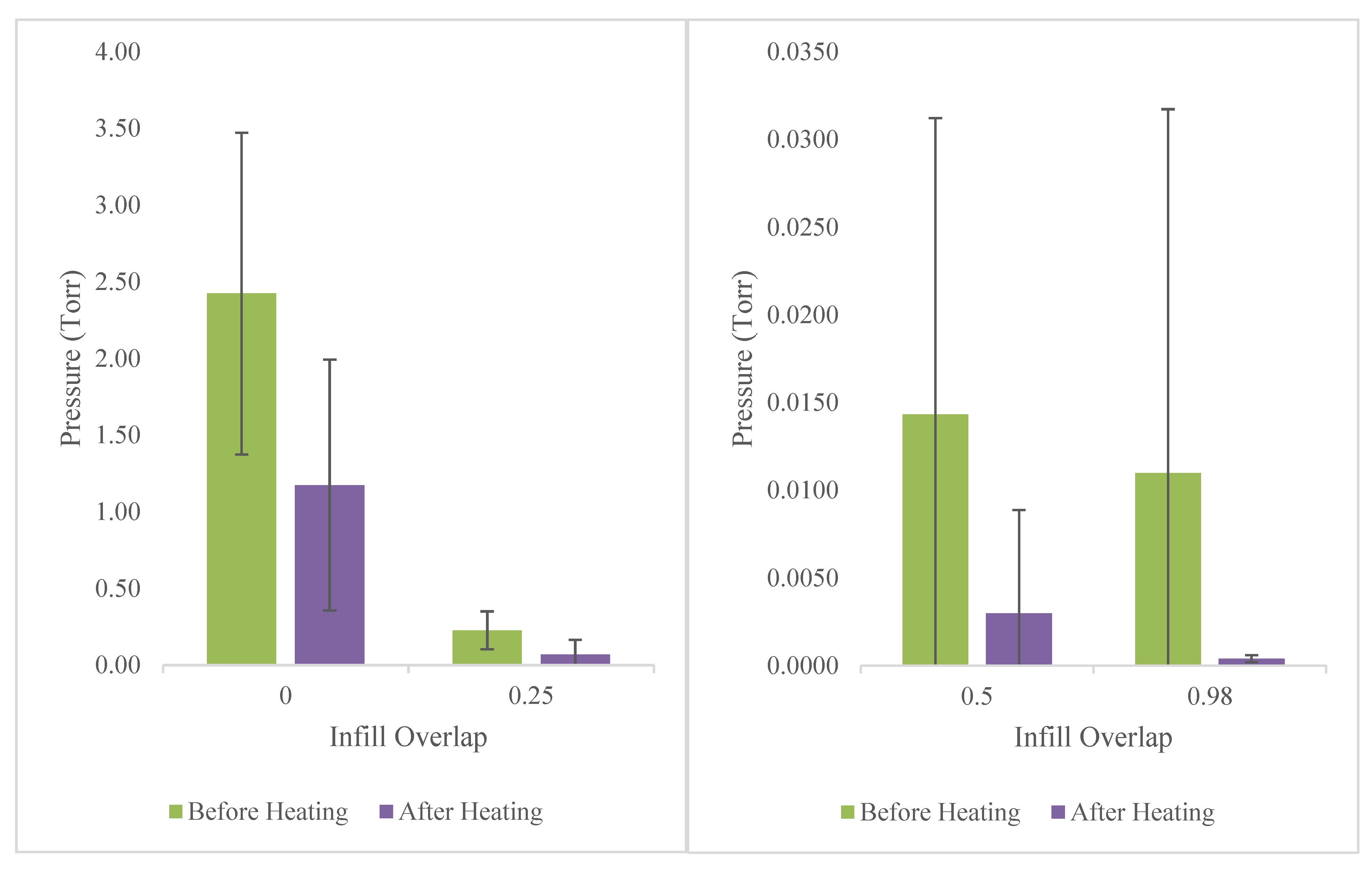
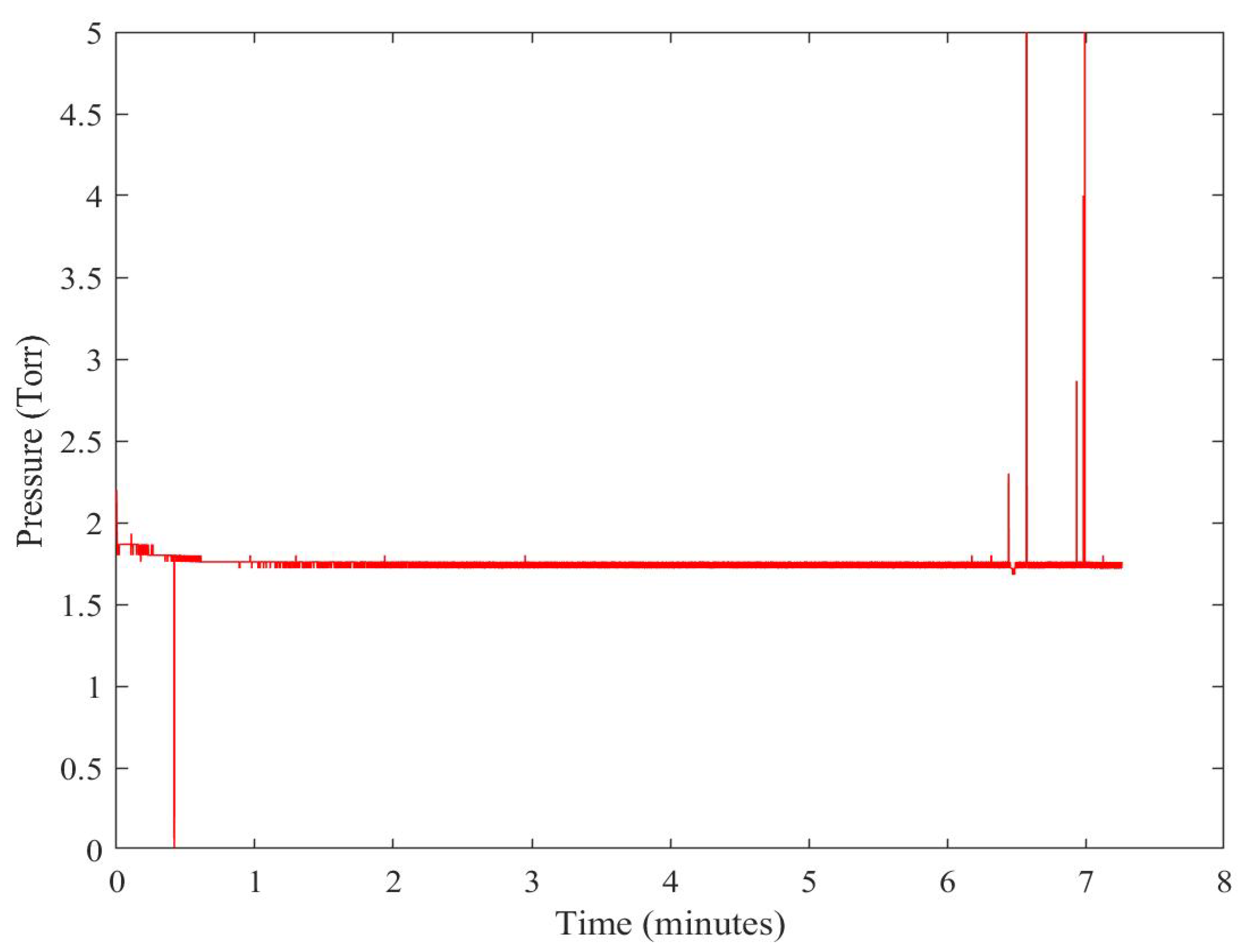
3. Results
4. Discussion
5. Conclusions
Author Contributions
Funding
Institutional Review Board Statement
Informed Consent Statement
Data Availability Statement
Conflicts of Interest
References
- Lubitz, M.; Medina, P.A.; Antic, A.; Rosin, J.T.; Fahlman, B.D. Cost-Effective Systems for Atomic Layer Deposition. J. Chem. Educ. 2014, 91, 1022–1027. [Google Scholar] [CrossRef]
- Pearce, J.M. Cut Costs with Open-Source Hardware. Nature 2014, 505, 618. [Google Scholar] [CrossRef]
- Fisher, D.K.; Gould, P.J. Open-Source Hardware Is a Low-Cost Alternative for Scientific Instrumentation and Research. Mod. Instrum. 2012, 1, 8–20. [Google Scholar] [CrossRef]
- Pearce, J.M. Open-Source Lab: How to Build Your Own Hardware and Reduce Research Costs, 1st ed.; Elsevier: Amsterdam, The Netherlands, 2013. [Google Scholar]
- Pearce, J.M. Building Research Equipment with Free, Open-Source Hardware. Science 2012, 337, 1303–1304. [Google Scholar] [CrossRef] [PubMed]
- Niezen, G.; Eslambolchilar, P.; Thimbleby, H. Open-Source Hardware for Medical Devices. BMJ Innov. 2016, 2, 78–83. [Google Scholar] [CrossRef] [PubMed]
- Pearce, J.M. Economic Savings for Scientific Free and Open Source Technology: A Review. HardwareX 2020, 8, e00139. [Google Scholar] [CrossRef]
- Oberloier, S.; Pearce, J.M. General Design Procedure for Free and Open-Source Hardware for Scientific Equipment. Designs 2018, 2, 2. [Google Scholar] [CrossRef]
- Sule, S.S.; Petsiuk, A.L.; Pearce, J.M. Open Source Completely 3-D Printable Centrifuge. Instruments 2019, 3, 30. [Google Scholar] [CrossRef]
- Baden, T.; Chagas, A.M.; Gage, G.; Marzullo, T.; Prieto-Godino, L.L.; Euler, T. Open Labware: 3-D Printing Your Own Lab Equipment. PLOS Biol. 2015, 13, e1002086. [Google Scholar] [CrossRef]
- Maia Chagas, A.; Molloy, J.C.; Prieto-Godino, L.L.; Baden, T. Leveraging Open Hardware to Alleviate the Burden of COVID-19 on Global Health Systems. PLOS Biol. 2020, 18, e3000730. [Google Scholar] [CrossRef] [Green Version]
- Singh, S.; Ramakrishna, S.; Singh, R. Material Issues in Additive Manufacturing: A Review. J. Manuf. Process. 2017, 25, 185–200. [Google Scholar] [CrossRef]
- Zander, N.E.; Gillan, M.; Burckhard, Z.; Gardea, F. Recycled Polypropylene Blends as Novel 3D Printing Materials. Addit. Manuf. 2019, 25, 122–130. [Google Scholar] [CrossRef]
- Kerns, J. Efficient Engineering: Will You Be Downloading 3D-Printed Products Directly from Amazon? Streamlined Online Shopping Presents Challenges to Anyone Trying to Start Consumer 3D Printing. Mach. Des. 2018, 90, 30–33. [Google Scholar]
- The Best 3D Printed Consumer Products. Available online: https://3dprintingindustry.com/news/the-best-3d-printed-consumer-products-148352/ (accessed on 24 February 2022).
- Brooks, G.; Kinsley, K.; Owens, T. 3D Printing as a Consumer Technology Business Model. Int. J. Manag. Inf. Syst. IJMIS 2014, 18, 271. [Google Scholar] [CrossRef]
- Petersen, E.; Pearce, J. Emergence of Home Manufacturing in the Developed World: Return on Investment for Open-Source 3-D Printers. Technologies 2017, 5, 7. [Google Scholar] [CrossRef]
- Bihari, N.; Heikkinen, I.T.S.; Marin, G.; Ekstrum, C.; Mayville, P.J.; Oberloier, S.; Savin, H.; Karppinen, M.; Pearce, J.M. Vacuum Outgassing Characteristics of Unpigmented 3D Printed Polymers Coated with Atomic Layer Deposited Alumina. J. Vac. Sci. Technol. A 2020, 38, 53204. [Google Scholar] [CrossRef]
- Barton, R.S.; Govier, R.P. A Mass Spectrometric Study of the Outgassing of Some Elastomers and Plastics (Outgassing Properties of Various Organic Polymers and Elastomers Used as Insulators and Seals in Vacuum Systems, Using Bakeable Mass Spectrometer). J. Vac. Sci. Technol. 1965, 2, 113–122. [Google Scholar] [CrossRef]
- Rivera, W.F.; Romero-Talamás, C.A. Vacuum Compatibility of 3-D-Printed Parts. IEEE Trans. Plasma Sci. 2016, 44, 874–876. [Google Scholar] [CrossRef]
- Liu, W.; Huo, Y.; Ke, C.; Cheng, J.; Guo, Y. 3D Printed Polymer Vacuum Insulator. IEEE Trans. Dielectr. Electr. Insul. 2021, 28, 28–32. [Google Scholar] [CrossRef]
- Hong, F.; Tendera, L.; Myant, C.; Boyle, D. Vacuum-Formed 3D Printed Electronics: Fabrication of Thin, Rigid and Free-Form Interactive Surfaces. SN Comput. Sci. 2022, 3, 275. [Google Scholar] [CrossRef]
- Heikkinen, I.T.S.; Marin, G.; Bihari, N.; Ekstrum, C.; Mayville, P.J.; Fei, Y.; Hu, Y.H.; Karppinen, M.; Savin, H.; Pearce, J.M. Atomic Layer Deposited Aluminum Oxide Mitigates Outgassing from Fused Filament Fabrication–Based 3-D Printed Components. Surf. Coat. Technol. 2020, 386, 125459. [Google Scholar] [CrossRef]
- Chaneliere, T. Vacuum Compatibility of ABS Plastics 3D-Printed Objects; CNRS, Laboratoire Aimé Cotton: Paris, France, 2017; p. 6. [Google Scholar]
- Mireles, J.; Adame, A.; Espalin, D.; Medina, F.; Winker, R.; Hoppe, T.; Zinniel, B.; Wicker, R. Analysis of Sealing Methods for FDM-Fabricated Parts. In Proceedings of the 2011 International Solid Freeform Fabrication Symposium, Austin, TX, USA, 8–10 August 2011; p. 12. [Google Scholar]
- SPI Supplies. Vacseal Products. Available online: https://www.2spi.com/category/vacseal/ (accessed on 15 July 2022).
- Gordeev, E.G.; Galushko, A.S.; Ananikov, V.P. Improvement of Quality of 3D Printed Objects by Elimination of Microscopic Structural Defects in Fused Deposition Modeling. PLoS ONE 2018, 13, e0198370. [Google Scholar] [CrossRef] [PubMed]
- Gelhausen, M.G.; Feuerbach, T.; Schubert, A.; Agar, D.W. 3D Printing for Chemical Process Laboratories I: Materials and Connection Principles. Chem. Eng. Technol. 2018, 41, 618–627. [Google Scholar] [CrossRef]
- Johannink, T.; Kreuzer, E.; Solowjow, E. Sealing of Machine Parts and Modules Manufactured with Desktop 3D Printers. Konstruktion 2017, 69, 63–73. [Google Scholar] [CrossRef]
- Lederle, F.; Kaldun, C.; Namyslo, J.C.; Hübner, E.G. 3D-Printing inside the Glovebox: A Versatile Tool for Inert-Gas Chemistry Combined with Spectroscopy. Helv. Chim. Acta 2016, 99, 255–266. [Google Scholar] [CrossRef]
- Kitson, P.J.; Glatzel, S.; Chen, W.; Lin, C.-G.; Song, Y.-F.; Cronin, L. 3D Printing of Versatile Reactionware for Chemical Synthesis. Nat. Protoc. 2016, 11, 920–936. [Google Scholar] [CrossRef]
- AL-Hasni, S.; Santori, G. 3D Printing of Vacuum and Pressure Tight Polymer Vessels for Thermally Driven Chillers and Heat Pumps. Vacuum 2020, 171, 109017. [Google Scholar] [CrossRef]
- Povilus, A.P.; Wurden, C.J.; Vendeiro, Z.; Baquero-Ruiz, M.; Fajans, J. Vacuum Compatibility of 3D-Printed Materials. J. Vac. Sci. Technol. Vac. Surf. Films 2014, 32, 33001. [Google Scholar] [CrossRef]
- Bergin, M.; Myles, T.A.; Radić, A.; Hatchwell, C.J.; Lambrick, S.M.; Ward, D.J.; Eder, S.D.; Fahy, A.; Barr, M.; Dastoor, P.C. Complex Optical Elements for Scanning Helium Microscopy through 3D Printing. J. Phys. Appl. Phys. 2021, 55, 95305. [Google Scholar] [CrossRef]
- Heikkinen, I.T.S.; Kauppinen, C.; Liu, Z.; Asikainen, S.M.; Spoljaric, S.; Seppälä, J.V.; Savin, H.; Pearce, J.M. Chemical Compatibility of Fused Filament Fabrication-Based 3-D Printed Components with Solutions Commonly Used in Semiconductor Wet Processing. Addit. Manuf. 2018, 23, 99–107. [Google Scholar] [CrossRef]
- LulzBot TAZ Aerostruder Tool Head. Available online: https://www.farnell.com/datasheets/2632879.pdf (accessed on 30 June 2022).
- OpenSCAD. Available online: https://openscad.org (accessed on 24 February 2022).
- Pearce, J.M.; Mayville, P.; Petsiuk, A. Heat Treating 3DP Tests. 2021. Available online: https://osf.io/36jch/ (accessed on 8 August 2022).
- Jones, R.; Haufe, P.; Sells, E.; Iravani, P.; Olliver, V.; Palmer, C.; Bowyer, A. RepRap—The Replicating Rapid Prototyper. Robotica 2011, 29, 177–191. [Google Scholar] [CrossRef] [Green Version]
- Sells, E.; Bailard, S.; Smith, Z.; Bowyer, A.; Olliver, V. RepRap: The Replicating Rapid Prototyper: Maximizing Customizability by Breeding the Means of Production. In Handbook of Research in Mass Customization and Personalization; World Scientific Publishing Company: Singapore, 2009; Volume 2, pp. 568–580. ISBN 978-981-4280-25-9. [Google Scholar]
- Bowyer, A. 3D Printing and Humanity’s First Imperfect Replicator. 3D Print. Addit. Manuf. 2014, 1, 4–5. [Google Scholar] [CrossRef]
- LulzBot TAZ 6. Available online: https://www.lulzbot.com/store/printers/lulzbot-taz-6 (accessed on 24 February 2022).
- OHAI: Open Hardware Assembly Instructions. Available online: https://ohai.lulzbot.com/project/lulzbot-taz-6-aerostruder-tool-head-installation/accessories/ (accessed on 30 June 2022).
- Ultimaker Polypropylene Filament-2.85 mm (0.5 kg). Available online: https://www.matterhackers.com/store/l/ultimaker-polypropylene-filament-300mm/sk/MMFT7T7W (accessed on 24 February 2022).
- Bachhar, N.; Gudadhe, A.; Kumar, A.; Andrade, P.; Kumaraswamy, G. 3D Printing of Semicrystalline Polypropylene: Towards Eliminating Warpage of Printed Objects. Bull. Mater. Sci. 2020, 43, 1–5. [Google Scholar] [CrossRef]
- Ultimaker 2+/3 Adhesion Sheets-Pack of 25. Available online: https://www.matterhackers.com/store/l/ultimaker-adhesion-sheets/sk/MNS7KT48 (accessed on 24 February 2022).
- Hough, P.V.C. Machine Analysis of Bubble Chamber Pictures. In Proceedings of the International Conference on High Energy Accelerators and Instrumentation, Geneva, Switzerland, 14–19 September 1959. [Google Scholar]
- Hough, P.V.C. Method and Means for Recognizing Complex Patterns. U.S. Patent 3,069,654, 18 December 1962. [Google Scholar]
- Duda, R.O.; Hart, P.E. Use of the Hough Transformation to Detect Lines and Curves in Pictures. Commun. ACM 1972, 15, 11–15. [Google Scholar] [CrossRef]
- Open Source Computer Vision (OpenCV): Hough Circle Transform. Available online: https://docs.opencv.org/4.x/da/d53/tutorial_py_houghcircles.html (accessed on 29 July 2022).
- Dizon, J.R.C.; Gache, C.C.L.; Cascolan, H.M.S.; Cancino, L.T.; Advincula, R.C. Post-Processing of 3D-Printed Polymers. Technologies 2021, 9, 61. [Google Scholar] [CrossRef]
- Karakurt, I.; Lin, L. 3D Printing Technologies: Techniques, Materials, and Post-Processing. Curr. Opin. Chem. Eng. 2020, 28, 134–143. [Google Scholar] [CrossRef]
- Johnson, P.R.; Copeland, P.M.; Ayodele, A.O.; Tarekegn, E.N.; Bromley, S.J.; Harrell, W.R.; Sosolik, C.E.; Marler, J.P. In-Vacuum Performance of a 3D-Printed Ion Deflector. Vacuum 2020, 172, 109061. [Google Scholar] [CrossRef]
- Zwicker, A.P.; Bloom, J.; Albertson, R.; Gershman, S. The Suitability of 3D Printed Plastic Parts for Laboratory Use. Am. J. Phys. 2015, 83, 281–285. [Google Scholar] [CrossRef]
- Pasanen, T.P.; von Gastrow, G.; Heikkinen, I.T.S.; Vähänissi, V.; Savin, H.; Pearce, J.M. Compatibility of 3-D Printed Devices in Cleanroom Environments for Semiconductor Processing. Mater. Sci. Semicond. Processing 2019, 89, 59–67. [Google Scholar] [CrossRef]
- Nuchitprasitchai, S.; Roggemann, M.C.; Pearce, J.M. Three Hundred and Sixty Degree Real-Time Monitoring of 3-D Printing Using Computer Analysis of Two Camera Views. J. Manuf. Mater. Processing 2017, 1, 2. [Google Scholar] [CrossRef]
- Paraskevoudis, K.; Karayannis, P.; Koumoulos, E.P. Real-Time 3D Printing Remote Defect Detection (Stringing) with Computer Vision and Artificial Intelligence. Processes 2020, 8, 1464. [Google Scholar] [CrossRef]
- Petsiuk, A.L.; Pearce, J.M. Open Source Computer Vision-Based Layer-Wise 3D Printing Analysis. Addit. Manuf. 2020, 36, 101473. [Google Scholar] [CrossRef]
- Jin, Z.; Zhang, Z.; Gu, G.X. Autonomous In-Situ Correction of Fused Deposition Modeling Printers Using Computer Vision and Deep Learning. Manuf. Lett. 2019, 22, 11–15. [Google Scholar] [CrossRef]
- Petsiuk, A.; Pearce, J.M. Towards Smart Monitored AM: Open Source in-Situ Layer-Wise 3D Printing Image Anomaly Detection Using Histograms of Oriented Gradients and a Physics-Based Rendering Engine. Addit. Manuf. 2022, 52, 102690. [Google Scholar] [CrossRef]
- Oberloier, S.; Whisman, N.G.; Pearce, J.M. Finding Ideal Parameters for Recycled Material Fused Particle Fabrication-Based 3D Printing Using an Open Source Software Implementation of Particle Swarm Optimization. 3D Print. Addit. Manuf. 2022. [Google Scholar] [CrossRef]
- Holcomb, G.; Caldona, E.B.; Cheng, X.; Advincula, R.C. On the Optimized 3D Printing and Post-Processing of PETG Materials. MRS Commun. 2022, 12, 381–387. [Google Scholar] [CrossRef]
- Wong, B.G.; Mancuso, C.P.; Kiriakov, S.; Bashor, C.J.; Khalil, A.S. Precise, Automated Control of Conditions for High-Throughput Growth of Yeast and Bacteria with EVOLVER. Nat. Biotechnol. 2018, 36, 614–623. [Google Scholar] [CrossRef] [PubMed]
- Bhandari, S.; Lopez-Anido, R.A.; Gardner, D.J. Enhancing the Interlayer Tensile Strength of 3D Printed Short Carbon Fiber Reinforced PETG and PLA Composites via Annealing. Addit. Manuf. 2019, 30, 100922. [Google Scholar] [CrossRef]


| Setting | Value | Setting | Value |
|---|---|---|---|
| Layer Thickness | 0.18 mm | Flow | 102% |
| Line Width | 0.5 mm | Retraction Distance | 4.5 mm |
| Z Seam | Random | Print Speed | 50 mm/s |
| Infill | 100% | Minimum Layer Time | 12 s |
Publisher’s Note: MDPI stays neutral with regard to jurisdictional claims in published maps and institutional affiliations. |
© 2022 by the authors. Licensee MDPI, Basel, Switzerland. This article is an open access article distributed under the terms and conditions of the Creative Commons Attribution (CC BY) license (https://creativecommons.org/licenses/by/4.0/).
Share and Cite
Mayville, P.J.; Petsiuk, A.L.; Pearce, J.M. Thermal Post-Processing of 3D Printed Polypropylene Parts for Vacuum Systems. J. Manuf. Mater. Process. 2022, 6, 98. https://doi.org/10.3390/jmmp6050098
Mayville PJ, Petsiuk AL, Pearce JM. Thermal Post-Processing of 3D Printed Polypropylene Parts for Vacuum Systems. Journal of Manufacturing and Materials Processing. 2022; 6(5):98. https://doi.org/10.3390/jmmp6050098
Chicago/Turabian StyleMayville, Pierce J., Aliaksei L. Petsiuk, and Joshua M. Pearce. 2022. "Thermal Post-Processing of 3D Printed Polypropylene Parts for Vacuum Systems" Journal of Manufacturing and Materials Processing 6, no. 5: 98. https://doi.org/10.3390/jmmp6050098
APA StyleMayville, P. J., Petsiuk, A. L., & Pearce, J. M. (2022). Thermal Post-Processing of 3D Printed Polypropylene Parts for Vacuum Systems. Journal of Manufacturing and Materials Processing, 6(5), 98. https://doi.org/10.3390/jmmp6050098