Article

Effect of the Laser Processing Parameters on the Selective Laser Melting of TiC–Fe-Based Cermets

by
Himanshu S. Maurya
1,*,
Lauri Kollo
1,
Marek Tarraste
1,
Kristjan Juhani
1,
Fjodor Sergejev
1 and
Konda Gokuldoss Prashanth
1,2,3,*
1
Department of Mechanical and Industrial Engineering, Tallinn University of Technology, Ehitajate tee 5, 19086 Tallinn, Estonia
2
Erich Schmid Institute of Materials Science, Austrian Academy of Sciences, Jahnstrasse 12, 8700 Leoben, Austria
3
Centre for Biomaterials, Cellular and Molecular Theranostics (CBCMT), School of Mechanical Engineering, Vellore Institute of Technology, Vellore 630014, India
*
Authors to whom correspondence should be addressed.
J. Manuf. Mater. Process. 2022, 6(2), 35; https://doi.org/10.3390/jmmp6020035
Submission received: 3 February 2022 / Revised: 1 March 2022 / Accepted: 11 March 2022 / Published: 13 March 2022
(This article belongs to the Special Issue Powder Metallurgy and Additive Manufacturing/3D Printing of Materials)

Abstract

:
The influence of laser pulse shaping on the formation of TiC-Fe-based cermets with different laser process parameters is investigated. The impact of pulse shaping and laser melting peak power on the microstructural development and mechanical properties of SLM-built parts is addressed. This research focuses primarily on the process parameters required to produce crack-free components and includes investigations of mechanical properties such as microhardness and fracture toughness. To acquire optimal process parameters, samples were manufactured using pulse shaping technology with varying laser melting peak power and exposure time. The influence of laser melting peak power and pulse shape on microstructure development and phases was analyzed using a scanning electron microscope and X-ray diffraction.

1. Introduction

WC–Co-, TiC-, and Ti (C, N)-based cermets are widely used for high-speed machining, drilling, and metal forming applications [1,2,3,4]. According to the European REACH (Registration, Evaluation, Authorization, and Restriction of Chemical Substances) program, conventional WC-based cermets in both powder and sintered form have been declared carcinogenic and toxic to human health. Titanium carbide-based cermets have proven to be a candidate material and alternative solution for replacing the conventional tungsten-cobalt (WC-Co)-based cermets for a wide range of applications over the years due to their unique properties [2]. These properties include a high melting temperature, a high hardness, good electrical conductivity, a high chemical resistance, and a relatively low density [5]. Because of these attractive properties, TiC-based cermets have been seen as an ideal choice for applications such as cutting tools, grinding wheels, wear-resistant coatings, and high-temperature heat exchangers [3,4,5]. 3D printing, or additive manufacturing (AM), is a new digital and green intelligent manufacturing process based on the design of a 3D CAD model and cumulative layered deposition. Selective laser melting (SLM) belongs to the category of laser powder-bed fusion (LBPF) AM technology has an attractive potential application in direct producing three-dimensional objects with complicated structures or geometry [6,7,8]. In comparison to conventional processes, SLM has many advantages, such as the ability to create complex structures, the ability to tune properties during processing, increased functionality, reduced lead times, etc. [9,10,11]. Furthermore, rapid solidification, repeating heating and cooling cycles, and temperature gradient during the SLM process often lead to a heterogeneous, fine, and anisotropic microstructure in the finished parts fabricated using SLM [12,13,14,15]. Parts fabricated with AM can, however, develop a variety of defects due to improper process parameters or disruptions during production [16,17].
The major hard component of modern cermets is TiC solid solution, with Co, Ni, Fe, and Mo, along with a number of different alloys, as a binder. The binder elements such as Ni and Co, however, are scarce and expensive, and their dust is particularly hazardous according to the U.S. NTP (National Toxicology Program). Hence, there exists a necessity of replacing this matrix entirely or partially with other non-harmful elements such as Fe due to its low cost, its ability to be hardened by heat treatment, and its high strength [18,19,20,21]. Processing of the cermets through additive manufacturing processes such as SLM is difficult and challenging due to its brittle nature [22]. The fabrication of cermets through standard laser pulse causes rapid melting and cooling of the melt pool, resulting in a complex thermal residual stress profile in the fabricated part, leading to defects such as cracks, delamination, and porosity [20,21,22,23,24].
Pulse shaping is a technique that helps in controlling heating/cooling by giving a shape to the pulse with variations in laser peak power and exposure time [25,26]. Pulse shaping helps in preheating and controlled cooling of the as-built parts during fabrication in the SLM process. Therefore, in this study, pulse shaping technique has been employed to fabricate TiC–Fe-based cermets as it helps to regulate the energy distribution of laser power during sample fabrication. These energy distributions have a substantial impact on the melting and cooling rates of the process. As a result of the controlled melting and cooling rate and the pre-heating effect of the powder bed, thermal residual stress may be reduced to a certain extent in the as-built parts during fabrication [27]. Preheating and controlled cooling of the powder bed and melt pool result in the reduction of the thermal gradient in the melt pool and, therefore, lower thermal stresses and decrease or eliminate cracks in the SLM-built parts [28,29,30]. Phase, microstructure formation, and mechanical properties such as microhardness and fracture toughness of SLM-processed as-built parts were investigated systematically and in detail under different laser pulse shaping process parameters.

2. Materials and Methods

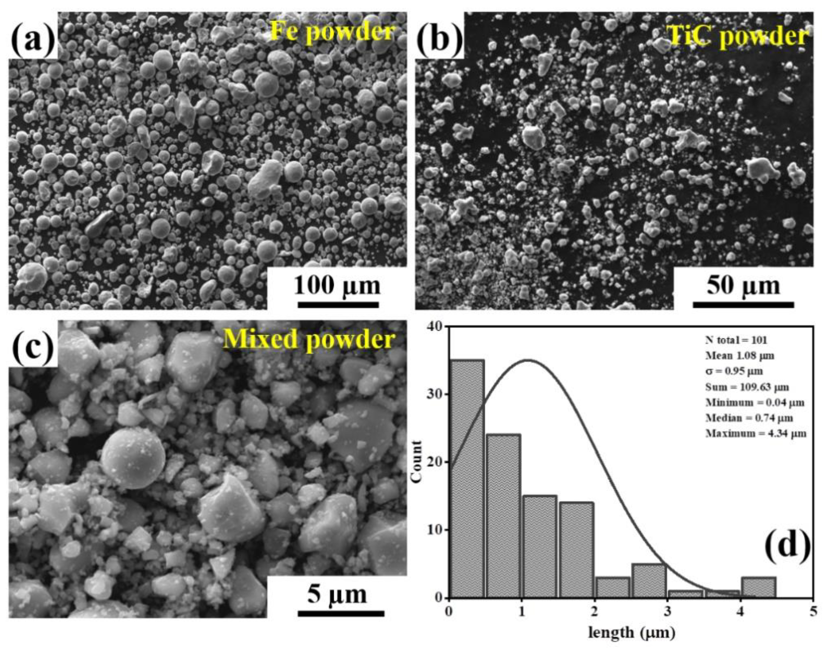
2.1. Powder Feedstock

The starting materials used in this study are TiC powder (Purity ≥ 99.9, average grain size ~2–3 µm; supplied by Pacific Particulate Materials Ltd., New Westminster, BC, Canada) and Fe powder (purity ≥ 99.8, average grain size ~45 µm; supplied by TLS Technik GmbH, Bitterfeld-Wolfen, Germany). The cermet powder is composed of TiC and Fe powder with a volume ratio of 70:30. With the help of a mechanical mixer, the powder was mechanically mixed for 24 h at 10 rpm with five Yttria Stabilized Zirconia (YSZ) balls (8 mm in diameter) as mixing media to provide attrition during mixing. In this case, milling and powder-to-ball ratio are not considered mixing parameters because a high number of balls may affect the particle size of the mixed powder, which eventually affects the rheology of the feedstock powder. Fe particles have a spherical shape and a wide size distribution (Figure 1a). On the other hand, TiC particles are irregular in shape with a narrow size distribution (Figure 1b). The cermet powder, after mechanical mixing, shows the presence of both spherical and irregularly shaped powder particles with a much wider distribution in their size (Figure 1c,d).

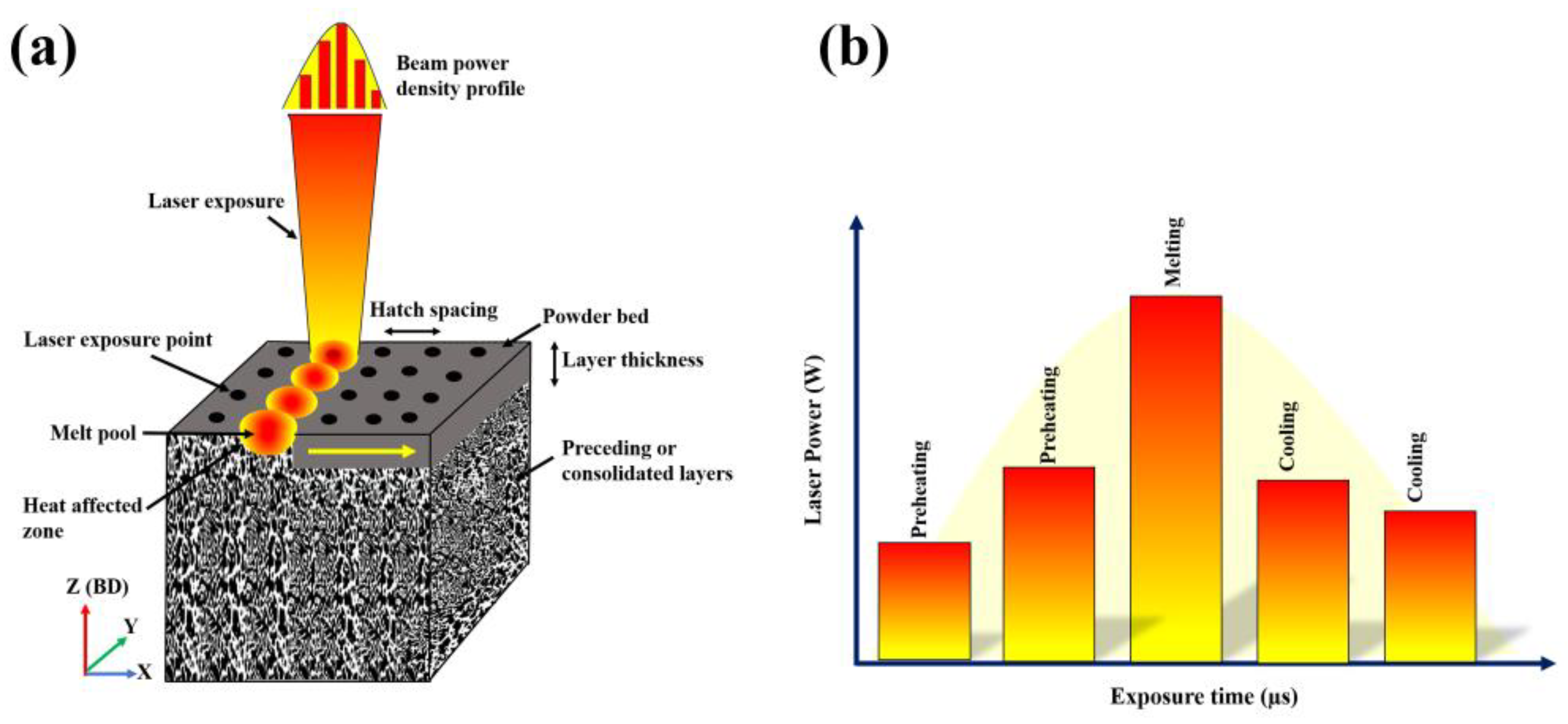
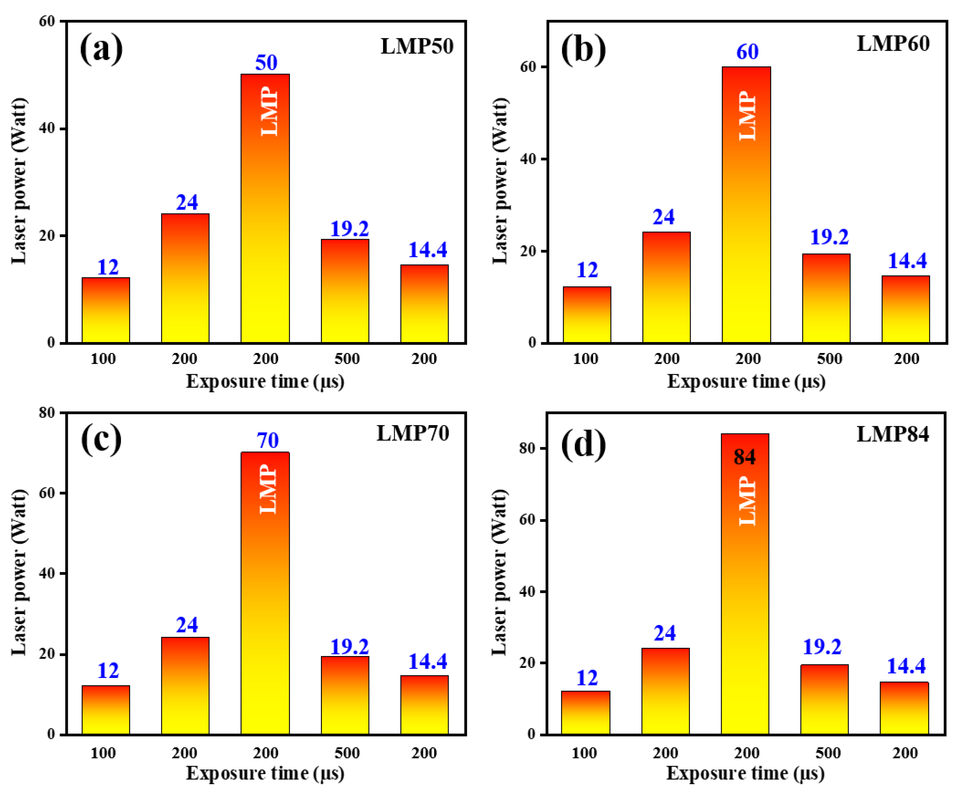
2.2. SLM Fabrication

A pulsed laser was used to produce TiC–Fe-based cermets using SLM Solutions GmbH Realizer SLM-50 machine, which is equipped with an Nd:YAG laser with a maximum power of 100 W. Cermet parts were fabricated using the pulse shaping laser technique. On the work surface, the focal diameter of the laser beam was fixed at 0.0134 mm and the SLM process was carried out in an argon atmosphere to prevent contamination and melt pool oxidation during fabrication of the parts. Cuboidal-shaped samples (5 mm × 5 mm × 3 mm) were fabricated using the pulse shaping technique with varying laser melting peak power (LMP) of 50, 60, 70, and 84 W and different laser exposure times for individual laser peaks, designated samples LMP50, LMP60, LMP70, and LMP84, respectively. With the employment of pulse shaping, the laser exposure was targeted to a laser exposure point designed by the 3D CAD software, and the same pulse was repeated for each exposure point in the powder bed. The samples were built vertically with a layer thickness of 0.035 mm and a point distance of 0.5 µm.
Figure 2 represents the pulse shaping of single laser pulse exposure with varying laser power and exposure time employed on a single exposure point. The same pulse is repeated at each exposure point of the powder bed for the fabrication of the cermet parts. Each pulse shaping contains several laser peaks with varying laser peak power and exposure time (Figure 2b). The peaks with low laser power were considered as pre-heating laser exposure to powder bed. The lower laser power and exposure duration can be referred to as a pre-pulse, which helps to pre-heat the powder bed before the melting peak laser LMP (50 W). Post-pulsing refers to cooling peaks that have a longer exposure period and lower laser power after the LMP exposure and it aids in the controlled cooling/heating of the molten pool. The same pulse shaping technique was used for all cermet as-built parts with varying laser peak power to investigate the effect on the microstructure formation of brittle materials such as TiC-based cermet and to eliminate defects such as cracks during formation. Figure 3 represents the SLM process parameter of the single pulse exposure employed for the fabrication of cermets with different LMP. The preheating and cooling laser peaks and exposure time are kept constant for all samples in the pulse shaping. In this work, point scanning is adapted for laser exposure with pulse shaping [22].
The laser power (P in watts), scan speed (v in millimeters per second), layer thickness (t in millimeters), and hatch distance (h in millimeters) are the four factors that influence fabrication and microstructure morphology of the as-built part and are considered when calculating the laser energy density (LED), This is calculated from the following equation [31].
LED = P v h t
Because the laser parameter of the LMP power varies in all samples, laser energy density of LMP is calculated for all samples and is shown in Table 1.

2.3. Microstructural Characterization and Mechancial Testing

For microstructural analysis, standard metallographic processing procedures for hard metals, such as the grinding and polishing process, were used to prepare bulk samples. Zeiss EVO MA15 scanning electron microscopes (SEM) equipped with EDS INCA were used to investigate the morphology and microstructure of the as-built parts through SLM. X-ray diffraction (XRD) measurements of the samples were performed on a Rigaku Ultima IV diffractometer with monochromatic Cu Kα radiation (λ = 1.5406 Å). All samples were studied in the 2θ range of 30–90° with a scan step of 0.02°.
Vickers microhardness measurements according to ASTM E384-17 were performed at room temperature utilizing Indentec 5030 KV (Indentec Hardness Testing Machines Limited, West Midlands, UK). A load of 1 kg and dwell time of 10 s was employed for the microhardness measurements. Fracture toughness KIC was determined by conventional indentation fracture toughness (IFT) method with 30 kg load and a dwell time of 10 s. A crack length measure was used to determine the fracture toughness of the as-built parts and study the toughness mechanism. Fracture toughness can be calculated by using the following equation [6]:
K I C = 0.15   H V l
where KIC is the fracture toughness, l is the sum of crack lengths of each indentation in mm, and HV1 is the hardness value in newtons per square millimeter. Four tests were carried out for all the mechanical property measurements in each sample and the mean value was determined.

3. Results and Discussion
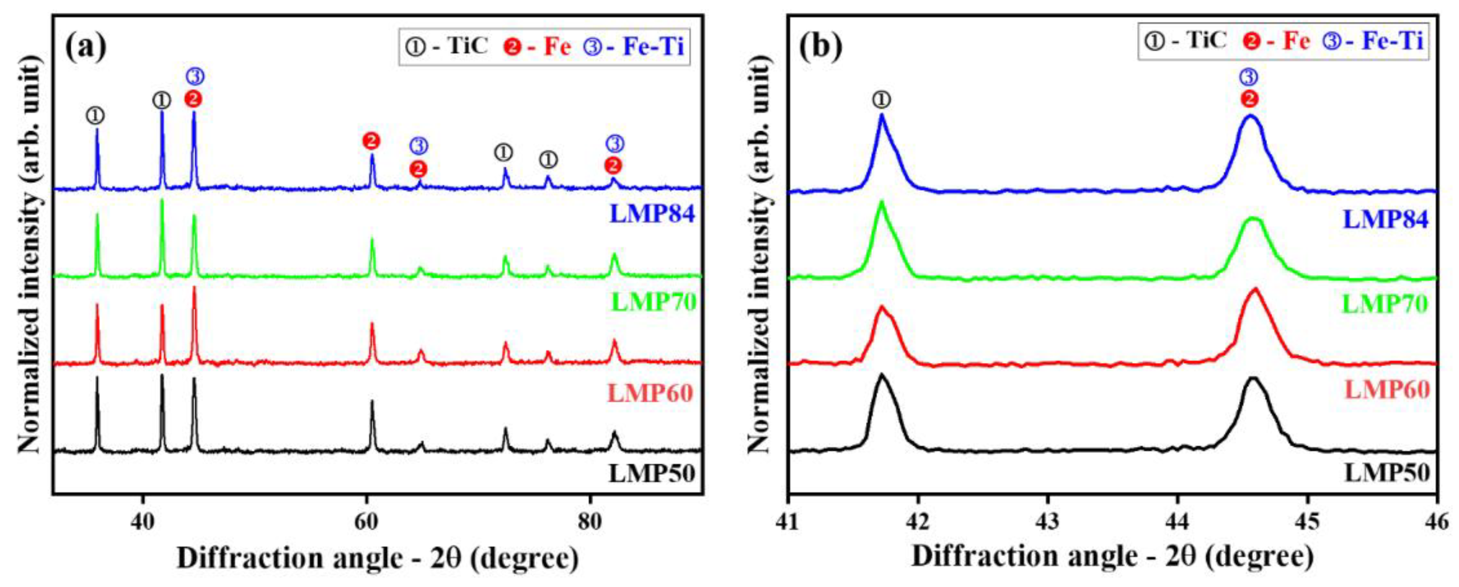
3.1. Phase Analysis

Figure 4 illustrates the X-ray diffraction patterns of the SLM as-built TiC–Fe-based cermets with different laser process parameters. All the XRD patterns exhibited prominent peaks of TiC and α-Fe and a solid solution of Fe–Ti, which suggests that the mixed powders do not lead to the formation of any new intermetallic carbide phases after SLM processing. Increasing the laser peak power results in a variation in the peak intensity of TiC and α-Fe. This significant variation in the intensity of TiC peaks can be attributed to the gradient morphology of the TiC and the binder phase as a function of the laser melting peak power. The magnified view of peaks of all the SLM-processed parts suggests that no major significant shift in peaks has been observed in all the fabricated parts irrespective of the changes in laser parameters.

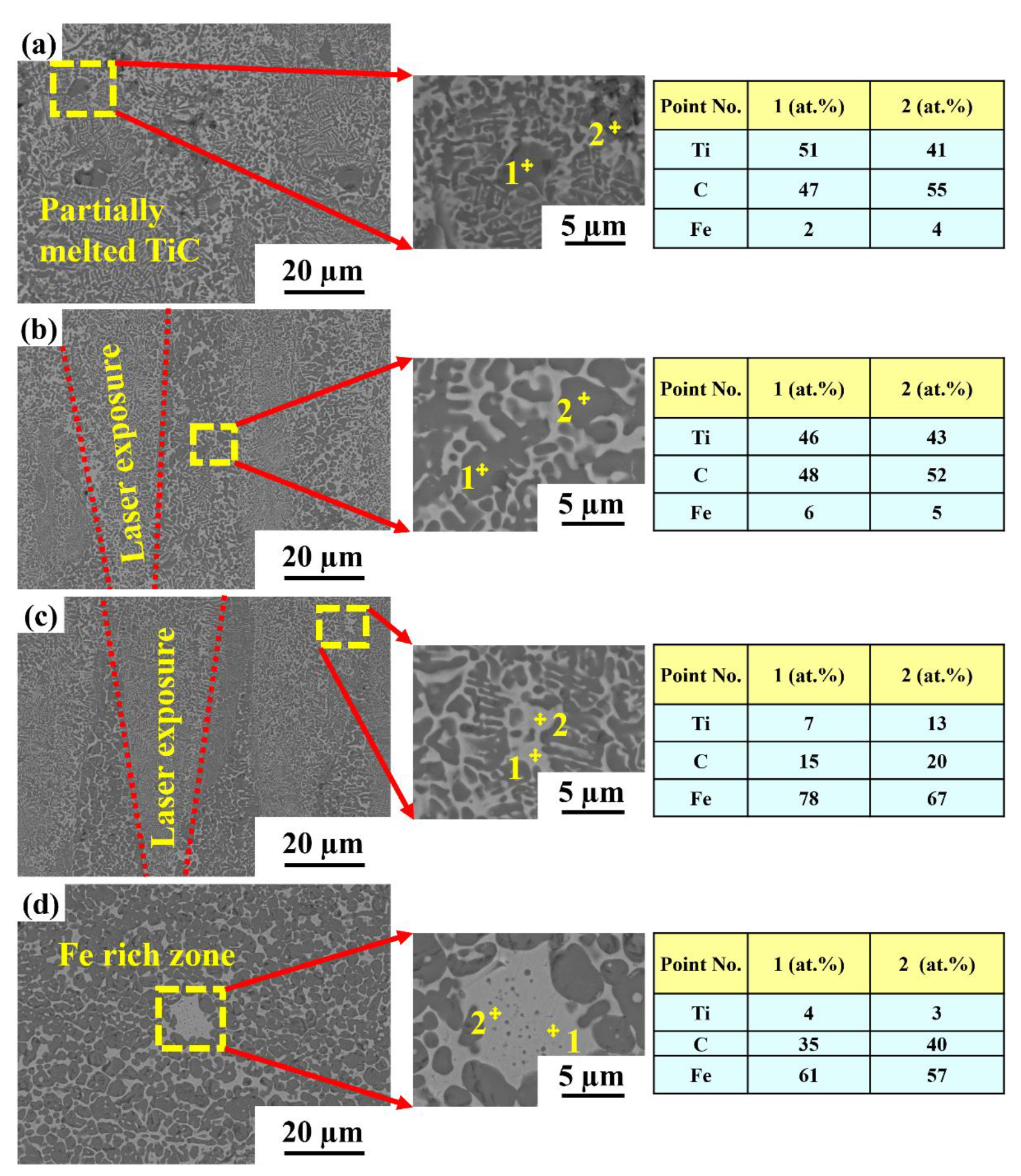
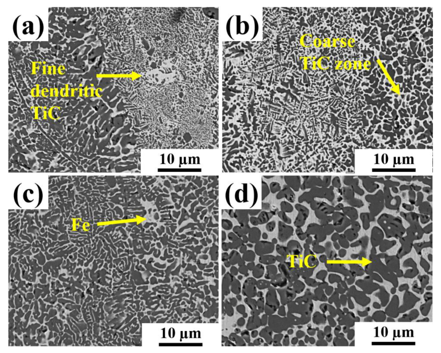
3.2. Microstructural Characterization

Figure 5 shows the surface morphology of the SLM-processed as-built samples fabricated through laser pulse shaping with different laser process parameters. All the SEM micrographs show the presence of phases with two different contrasts. The dark phase corresponds to TiC, while the bright contrast area corresponds to the Fe binder phase. For the pulse shaping, pre-heating and cooling parameters were kept the same. The only change in laser melting peak power has been made to study the effect of laser melting peak on the microstructure and formation of the sample. LMP50, with the lowest peak power (i.e., 50 W) (Figure 5a) shows a gradient in the TiC phase with an inhomogeneous distribution of the TiC phases. A fine dendritic TiC phase can be seen in the melt pool center, while a coarser dendritic microstructure has formed at the melt pool boundary, which is typical of most SLM-based microstructures. These gradients in the TiC phase can be explained through the Gaussian distribution of the laser in the melt pool. The product of temperature gradient (G) and solidification rate (R), known as cooling rate (T = G × R), affects the microstructure’s characteristics [26,27,28,29].
Changes in the morphology of cermets may occur when they are exposed to high temperatures combined with a high cooling rate (Figure 5b–d). In additive manufacturing processes such as SLM, high cooling rates can be achieved in the range of 103 to 1011 K/s [32,33,34,35,36]. The morphology of the microstructure may be changed due to a variety of factors: (i) intrinsic, such as variations in density or volume, densification, and oxidation at the surface; or (ii) extrinsic, such as strains developed by external forces and momentums or thermal or thermoplastic strains during cooling. Most commonly, one of these factors is the difference in coefficients of thermal expansion (CTE) between the two materials. When cooling from melting at high temperatures, the CTE (α) may cause a differential strain between layers that results in residual stress in the SLM-built part [33,37].
Pre-heating and controlled cooling of the powder bed help to avoid the sudden cooling or melting of the powder bed. This pulse shaping technique helps to increase powder bed temperature as a preheating effect and thus helps in lowering thermal residual stress generation. For the lower melting peak sample LMP50, unmelted or partially melted powder particles can be observed in the melt pool or laser scan area, which could be due to lower laser power and the inhomogeneous distribution of the powder particles [14]. However, increasing the laser melting peak power led to a fine dendritic TiC morphology with a lower gradient size in the TiC phases (dendritic and coarser) (Figure 6b,c). This may be attributed to an increment in laser melting peak power, which raises the laser energy density and thus increases the temperature in the melt pool, affecting the sample’s heating/cooling rate. Cooling rate increases with LMP energy density. However, further increasing the laser’s power resulted in coarsening of the microstructure with a uniform distribution of TiC (Figure 6d). The high energy of the laser beam, which results in variation of the cooling rate and non-equilibrium circumstances during solidification, may be to responsible for such microstructural characteristics. No cracks are observed on the surface of the sample processed through pulse shaping, indicating that the pulse shaping technique is beneficial for crack elimination and optimal for TiC–Fe-based cermets.

3.3. Mechanical Properties
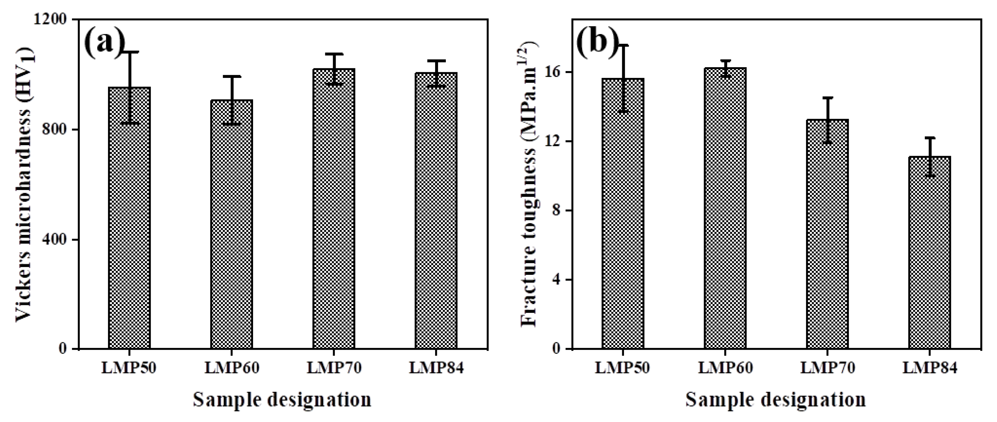
3.3.1. Hardness

Figure 7a shows the average microhardness values of TiC–Fe-based cermets fabricated by the SLM by pulse shaping with different LMP. The maximum hardness achieved for the SLM processed as-built parts was 1020 ± 53 HV1 for LMP70. The microhardness values for LMP50, LMP60, and LMP84, on the other hand, were 953 ± 130, 906 ± 86, and 1004 ± 46 HV1, respectively. The hard-ceramic phase volume area percentage and non-uniform distribution of the TiC particle can explain the variance in hardness values, since the indenter covers more of the harder phase in some areas and vice versa. The microhardness value shows a significant change as a function of the laser melting peak power. Because of the non-uniform distribution and significant gradient in TiC morphology, the microhardness value was low with a lower LMP (50 W). However, increasing LMP power (LMP60 and LMP70) makes the microstructure more homogeneous, which can lead to higher hardness for LMP70 with lower fluctuation in values due to higher volumetric quantity of TiC phases and more uniform distribution (Figure 6b,c). A low microhardness value has been observed for LMP84 with laser peak power (84 W) due to the presence of TiC phase coarsening, which may affect the microhardness value. The hardness values found in this study are equivalent to those reported in various previous studies [38,39,40]. The microhardness of TiC-based cermets, on the other hand, has been found to vary significantly depending on manufacturing technique, the type and amount of binder phase, and process defects during fabrication [31,37,41].

3.3.2. Fracture Toughness

Figure 7b shows the fracture toughness graph of the sample fabricated with different laser process parameters. The results show that measured fracture toughness has been affected by the LMP power [18,42,43]. Changing LMP power affects the microstructure and morphology of the finer and coarser TiC phases. Cermet’s toughness can be affected by the dual morphology of the phases of the TiC. For some as-built parts, the fracture toughness value shows large deviations, and there are many factors to be considered, such as crack systems, indenter geometry, the morphology of the ceramic and binder phase, etc. The maximum fracture toughness value is achieved for the sample with lower LMP. However, increasing LMP results in a decrease in the KIC value. The crack propagation mechanism could explain the variation in the fracture toughness value. The finer TiC particles lead to crack deviation more often, causing crack length to increase. As a result, the fracture toughness values for LMP50 and LMP60 are higher. Coarser microstructures impede the crack path, resulting in lower fracture toughness values for LMP84.
A stable crack propagation path was not achieved in the TiC-based cermets due to the high brittleness of the materials. Variation in TiC phase morphology affects the toughness mechanism of the SLM parts, which can be explained by the crack propagation behavior in the SLM parts (Figure 8). The larger particles of the TiC hinder crack propagation by deflection or bridging, and therefore consume fracture energy and improve the toughness of the material. The main toughness mechanisms of TiC–Fe-based cermets are the intergranular and transgranular bridging and deflection observed in the cracking behavior of the cermets under indentation load.

4. Conclusions

The fabrication of TiC–Fe-based cermets and the effects of laser process parameter with varying laser melting peak power have been studied, successfully adapting pulse-shaping technique through the SLM process. The following conclusions can be drawn from the present study:
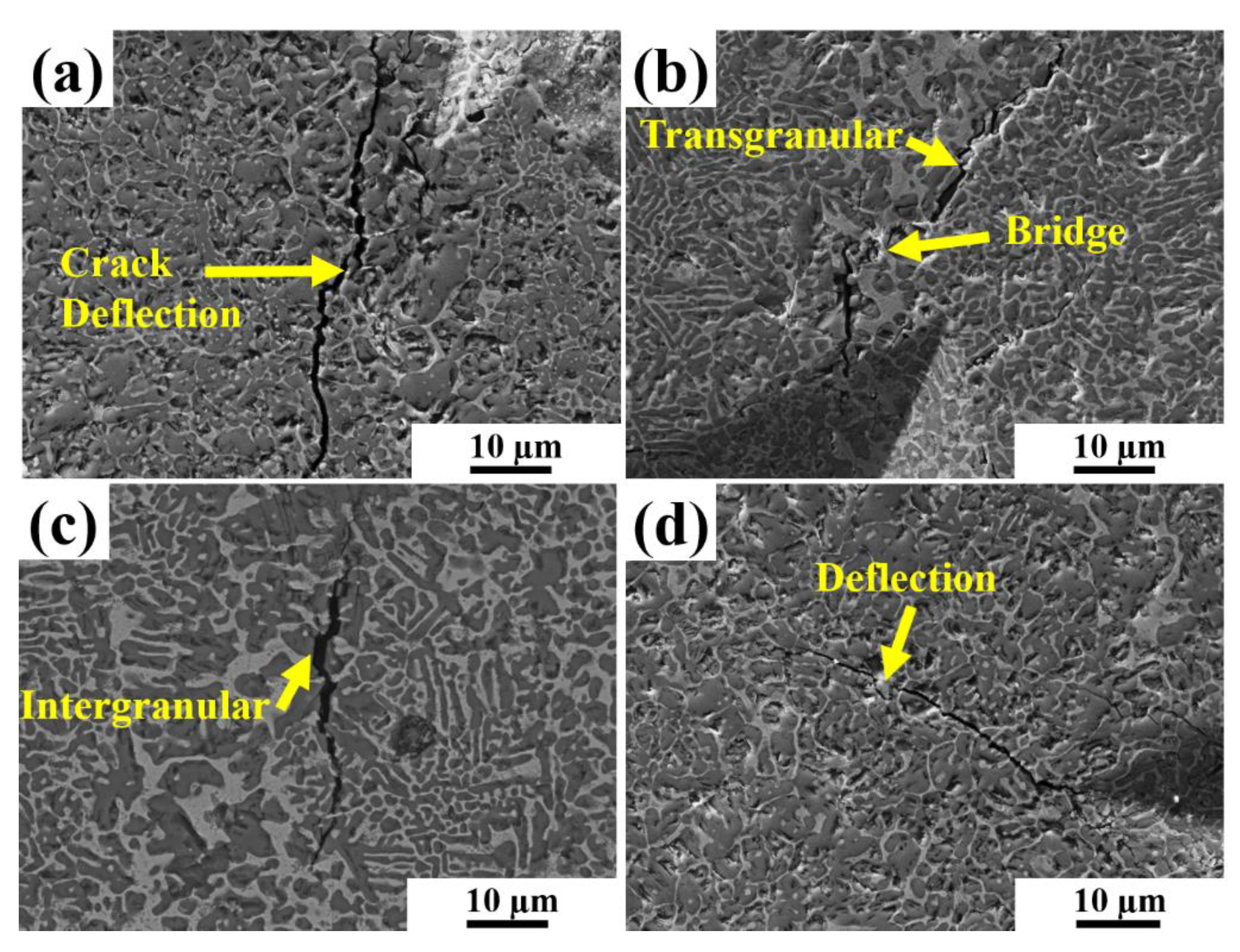
  • Laser melting peaks have an impact on the microstructure formation of the as-built parts. The microstructure of the sample changes from a coarser to a finer dendritic TiC phase as the laser melting peak power changes.
  • The melting/cooling rate is controlled by the laser peaks and exposure time of a single pulse during the solidification of the melt pool, which gradually influences the microstructure and mechanical properties of the samples.
  • In brittle materials such as TiC–Fe-based cermets, the laser pulse shaping technique appears to be an effective way to remove cracks in as-built samples by reducing thermal residual stress.
  • The maximum microhardness and fracture toughness achieved for the as-built parts were 1020 ± 53 HV1 for LMP70 and 16.2 ± 0.4 MPa m1/2 for LMP60.

Author Contributions

Conceptualization, H.S.M., L.K. and M.T.; Methodology, H.S.M., L.K. and M.T.; Validation, H.S.M., K.J., F.S. and K.G.P.; Formal analysis, H.S.M., L.K. and M.T.; Investigation, H.S.M., L.K. and M.T.; Resources, K.J., F.S. and K.G.P.; Writing—original draft preparation, H.S.M.; Writing—reviewing and editing H.S.M., L.K., F.S. and K.G.P.; Funding acquisition, K.J and K.G.P. All authors have read and agreed to the published version of the manuscript.

Funding

This research was funded by the Estonian Research Council (Grant: PRG1145) and European Regional Development Grant (Grant: ASTRA6-6).

Data Availability Statement

The present data forms a part of the ongoing study, and the results may be shared upon reasonable request from the corresponding authors.

Conflicts of Interest

Authors declare no conflict of interest.

References

  1. Kübarsepp, J.; Klaasen, H.; Pirso, J. Behavior of TiC-Base Cermets in Different Wear Conditions. Wear 2001, 249, 229–234. [Google Scholar] [CrossRef]
  2. Ettmayer, P. Hardmetals and Cermets. Annu. Rev. Mater. Sci. 1989, 19, 145–164. [Google Scholar] [CrossRef]
  3. Kenneth, J.A. Brookes Hardmetals and Other Hard Materials; International Carbide Data: East Barnet, Herts, UK, 1992. [Google Scholar]
  4. Kübarsepp, J.; Juhani, K. Cermets with Fe-Alloy Binder: A Review. Int. J. Refract. Met. Hard Mater. 2020, 92, 105290. [Google Scholar] [CrossRef]
  5. Das, K.; Bandyopadhyay, T.K.; Das, S. A Review on the Various Synthesis Routes of TiC Reinforced Ferrous Based Composites. J. Mater. Sci. 2002, 37, 3881–3892. [Google Scholar] [CrossRef]
  6. Wu, Y.; Xiong, J.; Guo, Z.; Yang, M.; Chen, J.; Xiong, S.; Fan, H.; Luo, J. Microstructure and fracture toughness of Ti(C0.7N0.3)-WC-Ni cermets. Int. J. Refract. Met. Hard Mater. 2011, 29, 85–89. [Google Scholar] [CrossRef]
  7. Oh, N.R.; Lee, S.K.; Hwang, K.C.; Hong, H.U. Characterization of Microstructure and Tensile Fracture Behavior in a Novel Infiltrated TiC-Steel Composite. Scr. Mater. 2016, 112, 123–127. [Google Scholar] [CrossRef]
  8. Prashanth, K.; Löber, L.; Klauss, H.-J.; Kühn, U.; Eckert, J. Characterization of 316L Steel Cellular Dodecahedron Structures Produced by Selective Laser Melting. Technologies 2016, 4, 34. [Google Scholar] [CrossRef] [Green Version]
  9. Herzog, D.; Seyda, V.; Wycisk, E.; Emmelmann, C. Additive Manufacturing of Metals. Acta Mater. 2016, 117, 371–392. [Google Scholar] [CrossRef]
  10. Singh, N.; Hameed, P.; Ummethala, R.; Manivasagam, G.; Prashanth, K.G.; Eckert, J. Selective Laser Manufacturing of Ti-Based Alloys and Composites: Impact of Process Parameters, Application Trends, and Future Prospects. Mater. Today Adv. 2020, 8, 100097. [Google Scholar] [CrossRef]
  11. Wang, P.; Eckert, J.; Prashanth, K.G.; Wu, M.W.; Kaban, I.; Xi, L.; Scudino, S. A Review of Particulate-Reinforced Aluminum Matrix Composites Fabricated by Selective Laser Melting. Trans. Nonferrous Met. Soc. China 2020, 30, 2001–2034. [Google Scholar] [CrossRef]
  12. Prashanth, K.G.; Scudino, S.; Klauss, H.J.; Surreddi, K.B.; Löber, L.; Wang, Z.; Chaubey, A.K.; Kühn, U.; Eckert, J. Microstructure and Mechanical Properties of Al-12Si Produced by Selective Laser Melting: Effect of Heat Treatment. Mater. Sci. Eng. A 2014, 590, 153–160. [Google Scholar] [CrossRef]
  13. DebRoy, T.; Wei, H.L.; Zuback, J.S.; Mukherjee, T.; Elmer, J.W.; Milewski, J.O.; Beese, A.M.; Wilson-Heid, A.; De, A.; Zhang, W. Additive Manufacturing of Metallic Components—Process, Structure and Properties. Prog. Mater. Sci. 2018, 92, 112–224. [Google Scholar] [CrossRef]
  14. Wang, Z.; Xie, M.; Li, Y.; Zhang, W.; Yang, C.; Kollo, L.; Eckert, J.; Prashanth, K.G. Premature Failure of an Additively Manufactured Material. NPG Asia Mater. 2020, 12, 30. [Google Scholar] [CrossRef]
  15. Maity, T.; Chawake, N.; Kim, J.T.; Eckert, J.; Prashanth, K.G. Anisotropy in Local Microstructure—Does It Affect the Tensile Properties of the SLM Samples? Manuf. Lett. 2018, 15, 33–37. [Google Scholar] [CrossRef]
  16. Zhao, C.; Wang, Z.; Li, D.; Kollo, L.; Luo, Z.; Zhang, W.; Gokuldoss, K.; Prashanth, K.G. Selective Laser Melting of Cu—Ni—Sn: A Comprehensive Study on the Microstructure, Mechanical Properties, and Deformation Behavior. Int. J. Plast. 2021, 138, 102926. [Google Scholar] [CrossRef]
  17. Prashanth, K.G.; Scudino, S.; Maity, T.; Das, J.; Eckert, J. Is the Energy Density a Reliable Parameter for Materials Synthesis by Selective Laser Melting? Mater. Res. Lett. 2017, 5, 386–390. [Google Scholar] [CrossRef] [Green Version]
  18. Suryawanshi, J.; Prashanth, K.G.; Scudino, S.; Eckert, J.; Prakash, O.; Ramamurty, U. Simultaneous Enhancements of Strength and Toughness in an Al-12Si Alloy Synthesized Using Selective Laser Melting. Acta Mater. 2016, 115, 285–294. [Google Scholar] [CrossRef]
  19. Zhang, B.; Li, Y.; Bai, Q. Defect Formation Mechanisms in Selective Laser Melting: A Review. Chin. J. Mech. Eng. 2017, 30, 515–527. [Google Scholar] [CrossRef] [Green Version]
  20. Klaasen, H.; Kollo, L.; Kübarsepp, J. Mechanical Properties and Wear Performance of Compression Sintered TiC Based Cermets. Powder Metall. 2007, 50, 132–136. [Google Scholar] [CrossRef]
  21. Santos, E.C.; Osakada, K.; Shiomi, M.; Kitamura, Y.; Abe, F. Microstructure and Mechanical Properties of Pure Titanium Models Fabricated by Selective Laser Melting. Proc. Inst. Mech. Eng. Part C J. Mech. Eng. Sci. 2004, 218, 711–719. [Google Scholar] [CrossRef]
  22. Maurya, H.S.; Kollo, L.; Tarraste, M.; Juhani, K.; Sergejev, F.; Prashanth, K.G. Selective Laser Melting of TiC-Fe via Laser Pulse Shaping: Microstructure and Mechanical Properties. 3D Print. Addit. Manuf. 2021; ahead of print. [Google Scholar]
  23. Prashanth, K.G.; Shakur Shahabi, H.; Attar, H.; Srivastava, V.C.; Ellendt, N.; Uhlenwinkel, V.; Eckert, J.; Scudino, S. Production of High Strength Al85Nd8Ni5Co2 Alloy by Selective Laser Melting. Addit. Manuf. 2015, 6, 1–5. [Google Scholar] [CrossRef]
  24. Schwab, H.; Prashanth, K.G.; Löber, L.; Kühn, U.; Eckert, J. Selective Laser Melting of Ti-45Nb Alloy. Metals 2015, 5, 686–694. [Google Scholar] [CrossRef] [Green Version]
  25. Mumtaz, K.; Hopkinson, N. Selective Laser Melting of Inconel 625 Using Pulse Shaping. Rapid Prototyp. J. 2010, 16, 248–257. [Google Scholar] [CrossRef] [Green Version]
  26. Demir, A.G.; Pangovski, K.; O’Neill, W.; Previtali, B. Investigation of Pulse Shape Characteristics on the Laser Ablation Dynamics of TiN Coatings in the Ns Regime. J. Phys. D Appl. Phys. 2015, 48, 235202. [Google Scholar] [CrossRef]
  27. Mumtaz, K.A.; Hopkinson, N. Selective Laser Melting of Thin Wall Parts Using Pulse Shaping. J. Mater. Processing Technol. 2010, 210, 279–287. [Google Scholar] [CrossRef]
  28. Tonelli, L.; Fortunato, A.; Ceschini, L. CoCr Alloy Processed by Selective Laser Melting (SLM): Effect of Laser Energy Density on Microstructure, Surface Morphology, and Hardness. J. Manuf. Processes 2020, 52, 106–119. [Google Scholar] [CrossRef]
  29. Bian, P.; Shi, J.; Liu, Y.; Xie, Y. Influence of Laser Power and Scanning Strategy on Residual Stress Distribution in Additively Manufactured 316L Steel. Opt. Laser Technol. 2020, 132, 106477. [Google Scholar] [CrossRef]
  30. Waqar, S.; Guo, K.; Sun, J. Evolution of Residual Stress Behavior in Selective Laser Melting (SLM) of 316L Stainless Steel through Preheating and in-Situ Re-Scanning Techniques. Opt. Laser Technol. 2022, 149, 107806. [Google Scholar] [CrossRef]
  31. Yu, Z.; Xu, Z.; Guo, Y.; Xin, R.; Liu, R.; Jiang, C.; Li, L.; Zhang, Z.; Ren, L. Study on Properties of SLM-NiTi Shape Memory Alloy under the Same Energy Density. J. Mater. Res. Technol. 2021, 13, 241–250. [Google Scholar] [CrossRef]
  32. Gu, D.; Hagedorn, Y.C.; Meiners, W.; Meng, G.; Batista, R.J.S.; Wissenbach, K.; Poprawe, R. Densification Behavior, Microstructure Evolution, and Wear Performance of Selective Laser Melting Processed Commercially Pure Titanium. Acta Mater. 2012, 60, 3849–3860. [Google Scholar] [CrossRef]
  33. Prashanth, K.G.; Debalina, B.; Wang, Z.; Gostin, P.F.; Gebert, A.; Calin, M.; Kühn, U.; Kamaraj, M.; Scudino, S.; Eckert, J. Tribological and Corrosion Properties of Al-12Si Produced by Selective Laser Melting. J. Mater. Res. 2014, 29, 2044–2054. [Google Scholar] [CrossRef]
  34. Zhao, C.; Wang, Z.; Li, D.; Kollo, L.; Luo, Z.; Zhang, W.; Prashanth, K.G. Cu-Ni-Sn Alloy Fabricated by Melt Spinning and Selective Laser Melting: A Comparative Study on the Microstructure and Formation Kinetics. J. Mater. Res. Technol. 2020, 9, 13097–13105. [Google Scholar] [CrossRef]
  35. Prashanth, K.; Scudino, S.; Chatterjee, R.; Salman, O.; Eckert, J. Additive Manufacturing: Reproducibility of Metallic Parts. Technologies 2017, 5, 8. [Google Scholar] [CrossRef] [Green Version]
  36. Gokuldoss Prashanth, K.; Scudino, S.; Eckert, J. Tensile Properties of Al-12Si Fabricated via Selective Laser Melting (SLM) at Different Temperatures. Technologies 2016, 4, 38. [Google Scholar] [CrossRef] [Green Version]
  37. Yan, C.; Hao, L.; Hussein, A.; Young, P.; Huang, J.; Zhu, W. Microstructure and Mechanical Properties of Aluminium Alloy Cellular Lattice Structures Manufactured by Direct Metal Laser Sintering. Mater. Sci. Eng. A 2015, 628, 238–246. [Google Scholar] [CrossRef]
  38. Sahoo, C.K.; Masanta, M. Microstructure and Mechanical Properties of TiC-Ni Coating on AISI304 Steel Produced by TIG Cladding Process. J. Mater. Processing Technol. 2017, 240, 126–137. [Google Scholar] [CrossRef]
  39. Gaier, M.; Todorova, T.Z.; Russell, Z.; Farhat, Z.N.; Zwanziger, J.W.; Plucknett, K.P. The Influence of Intermetallic Ordering on Wear and Indentation Properties of TiC-Ni3 Al Cermets. Wear 2019, 426–427, 390–400. [Google Scholar] [CrossRef]
  40. Lu, L.; Fuh, J.Y.H.; Chen, Z.D.; Leong, C.C.; Wong, Y.S. In Situ Formation of TiC Composite Using Selective Laser Melting. Mater. Res. Bull. 2000, 35, 1555–1561. [Google Scholar] [CrossRef]
  41. Li, W.; Li, S.; Liu, J.; Zhang, A.; Zhou, Y.; Wei, Q.; Yan, C.; Shi, Y. Effect of Heat Treatment on AlSi10Mg Alloy Fabricated by Selective Laser Melting: Microstructure Evolution, Mechanical Properties and Fracture Mechanism. Mater. Sci. Eng. A 2016, 663, 116–125. [Google Scholar] [CrossRef]
  42. Suryawanshi, J.; Prashanth, K.G.; Ramamurty, U. Tensile, Fracture, and Fatigue Crack Growth Properties of a 3D Printed Maraging Steel through Selective Laser Melting. J. Alloy. Compd. 2017, 725, 355–364. [Google Scholar] [CrossRef]
  43. Suryawanshi, J.; Prashanth, K.G.; Ramamurty, U. Mechanical Behavior of Selective Laser Melted 316L Stainless Steel. Mater. Sci. Eng. A 2017, 696, 113–121. [Google Scholar] [CrossRef]
Figure 1. Scanning electron microscopy images of the initial powders (a) Fe powder; (b) TiC powder; (c) mechanically mixed powder; and (d) particle size distribution of the mixed powder.
Jmmp 06 00035 g001
Figure 2. Schematics of the (a) SLM processing and laser exposure to powder bed, and (b) and single laser pulse to exposure point through pulse shaping technique.
Jmmp 06 00035 g002
Figure 3. Pulse shaping parameter showing the detail of a single pulse employed for the fabrication of TiC–Fe-based cermets with different laser melting peaks power (LMP) (a) LMP50, (b) LMP60, (c) LMP70, and (d) LMP84.
Jmmp 06 00035 g003
Figure 4. X-ray diffraction patterns of TiC-based cermets (a) as-built parts with different laser melting peak power processed through selective laser melting and (b) magnified view of the peaks.
Jmmp 06 00035 g004
Figure 5. Scanning electron micrograph of the longitudinal section/side view and energy dispersive spectrum point analysis of the SLM processed cermets fabricated with different laser melting peak power (a) LMP50, (b) LMP60, (c) LMP70, and (d) LMP84.
Jmmp 06 00035 g005
Figure 6. High magnification microstructures of the as-built cermets showing characteristic morphology of the TiC along the longitudinal section with different laser melting peak power for pulse shaping. (a) LMP50, (b) LMP60, (c) LMP70, and (d) LMP84.
Jmmp 06 00035 g006
Figure 7. Mechanical properties micrograph of TiC-based cermets fabricated as a function of laser melting peak by the SLM process (a)Vickers microhardness and (b) fracture toughness.
Jmmp 06 00035 g007
Figure 8. SEM images of the crack propagation path in TiC–Fe cermet with different laser process parameters (a) LMP50, (b) LMP60, (c) LMP70, (d) LMP84.
Jmmp 06 00035 g008
Table 1. Process parameters employed for the fabrication of SLM parts with different laser energy densities of LMP.
LMP (W)v (mm/s)h (mm)t (mm)LED (J/mm3)
50; 60; 70; 842500.050.035114.2; 137.1; 160.0; 192.0
Publisher’s Note: MDPI stays neutral with regard to jurisdictional claims in published maps and institutional affiliations.

